EP3840941B1 - Verfahren zum herstellen einer schweissverbindung sowie schweissgerät - Google Patents
Verfahren zum herstellen einer schweissverbindung sowie schweissgerät Download PDFInfo
- Publication number
- EP3840941B1 EP3840941B1 EP19734229.8A EP19734229A EP3840941B1 EP 3840941 B1 EP3840941 B1 EP 3840941B1 EP 19734229 A EP19734229 A EP 19734229A EP 3840941 B1 EP3840941 B1 EP 3840941B1
- Authority
- EP
- European Patent Office
- Prior art keywords
- welding
- error
- target value
- connecting element
- conductor resistance
- Prior art date
- Legal status (The legal status is an assumption and is not a legal conclusion. Google has not performed a legal analysis and makes no representation as to the accuracy of the status listed.)
- Active
Links
Images
Classifications
-
- B—PERFORMING OPERATIONS; TRANSPORTING
- B29—WORKING OF PLASTICS; WORKING OF SUBSTANCES IN A PLASTIC STATE IN GENERAL
- B29C—SHAPING OR JOINING OF PLASTICS; SHAPING OF MATERIAL IN A PLASTIC STATE, NOT OTHERWISE PROVIDED FOR; AFTER-TREATMENT OF THE SHAPED PRODUCTS, e.g. REPAIRING
- B29C66/00—General aspects of processes or apparatus for joining preformed parts
- B29C66/80—General aspects of machine operations or constructions and parts thereof
- B29C66/87—Auxiliary operations or devices
- B29C66/872—Starting or stopping procedures
-
- B—PERFORMING OPERATIONS; TRANSPORTING
- B29—WORKING OF PLASTICS; WORKING OF SUBSTANCES IN A PLASTIC STATE IN GENERAL
- B29C—SHAPING OR JOINING OF PLASTICS; SHAPING OF MATERIAL IN A PLASTIC STATE, NOT OTHERWISE PROVIDED FOR; AFTER-TREATMENT OF THE SHAPED PRODUCTS, e.g. REPAIRING
- B29C65/00—Joining or sealing of preformed parts, e.g. welding of plastics materials; Apparatus therefor
- B29C65/02—Joining or sealing of preformed parts, e.g. welding of plastics materials; Apparatus therefor by heating, with or without pressure
- B29C65/18—Joining or sealing of preformed parts, e.g. welding of plastics materials; Apparatus therefor by heating, with or without pressure using heated tools
- B29C65/22—Heated wire resistive ribbon, resistive band or resistive strip
-
- B—PERFORMING OPERATIONS; TRANSPORTING
- B29—WORKING OF PLASTICS; WORKING OF SUBSTANCES IN A PLASTIC STATE IN GENERAL
- B29C—SHAPING OR JOINING OF PLASTICS; SHAPING OF MATERIAL IN A PLASTIC STATE, NOT OTHERWISE PROVIDED FOR; AFTER-TREATMENT OF THE SHAPED PRODUCTS, e.g. REPAIRING
- B29C66/00—General aspects of processes or apparatus for joining preformed parts
- B29C66/90—Measuring or controlling the joining process
- B29C66/96—Measuring or controlling the joining process characterised by the method for implementing the controlling of the joining process
- B29C66/967—Measuring or controlling the joining process characterised by the method for implementing the controlling of the joining process involving special data inputs or special data outputs, e.g. for monitoring purposes
- B29C66/9672—Measuring or controlling the joining process characterised by the method for implementing the controlling of the joining process involving special data inputs or special data outputs, e.g. for monitoring purposes involving special data inputs, e.g. involving barcodes, RFID tags
-
- B—PERFORMING OPERATIONS; TRANSPORTING
- B29—WORKING OF PLASTICS; WORKING OF SUBSTANCES IN A PLASTIC STATE IN GENERAL
- B29C—SHAPING OR JOINING OF PLASTICS; SHAPING OF MATERIAL IN A PLASTIC STATE, NOT OTHERWISE PROVIDED FOR; AFTER-TREATMENT OF THE SHAPED PRODUCTS, e.g. REPAIRING
- B29C65/00—Joining or sealing of preformed parts, e.g. welding of plastics materials; Apparatus therefor
- B29C65/02—Joining or sealing of preformed parts, e.g. welding of plastics materials; Apparatus therefor by heating, with or without pressure
- B29C65/18—Joining or sealing of preformed parts, e.g. welding of plastics materials; Apparatus therefor by heating, with or without pressure using heated tools
- B29C65/22—Heated wire resistive ribbon, resistive band or resistive strip
- B29C65/221—Heated wire resistive ribbon, resistive band or resistive strip characterised by the type of heated wire, resistive ribbon, band or strip
- B29C65/222—Heated wire resistive ribbon, resistive band or resistive strip characterised by the type of heated wire, resistive ribbon, band or strip comprising at least a single heated wire
-
- B—PERFORMING OPERATIONS; TRANSPORTING
- B29—WORKING OF PLASTICS; WORKING OF SUBSTANCES IN A PLASTIC STATE IN GENERAL
- B29C—SHAPING OR JOINING OF PLASTICS; SHAPING OF MATERIAL IN A PLASTIC STATE, NOT OTHERWISE PROVIDED FOR; AFTER-TREATMENT OF THE SHAPED PRODUCTS, e.g. REPAIRING
- B29C65/00—Joining or sealing of preformed parts, e.g. welding of plastics materials; Apparatus therefor
- B29C65/02—Joining or sealing of preformed parts, e.g. welding of plastics materials; Apparatus therefor by heating, with or without pressure
- B29C65/18—Joining or sealing of preformed parts, e.g. welding of plastics materials; Apparatus therefor by heating, with or without pressure using heated tools
- B29C65/24—Joining or sealing of preformed parts, e.g. welding of plastics materials; Apparatus therefor by heating, with or without pressure using heated tools characterised by the means for heating the tool
- B29C65/30—Electrical means
-
- B—PERFORMING OPERATIONS; TRANSPORTING
- B29—WORKING OF PLASTICS; WORKING OF SUBSTANCES IN A PLASTIC STATE IN GENERAL
- B29C—SHAPING OR JOINING OF PLASTICS; SHAPING OF MATERIAL IN A PLASTIC STATE, NOT OTHERWISE PROVIDED FOR; AFTER-TREATMENT OF THE SHAPED PRODUCTS, e.g. REPAIRING
- B29C65/00—Joining or sealing of preformed parts, e.g. welding of plastics materials; Apparatus therefor
- B29C65/02—Joining or sealing of preformed parts, e.g. welding of plastics materials; Apparatus therefor by heating, with or without pressure
- B29C65/34—Joining or sealing of preformed parts, e.g. welding of plastics materials; Apparatus therefor by heating, with or without pressure using heated elements which remain in the joint, e.g. "verlorenes Schweisselement"
- B29C65/3404—Joining or sealing of preformed parts, e.g. welding of plastics materials; Apparatus therefor by heating, with or without pressure using heated elements which remain in the joint, e.g. "verlorenes Schweisselement" characterised by the type of heated elements which remain in the joint
- B29C65/342—Joining or sealing of preformed parts, e.g. welding of plastics materials; Apparatus therefor by heating, with or without pressure using heated elements which remain in the joint, e.g. "verlorenes Schweisselement" characterised by the type of heated elements which remain in the joint comprising at least a single wire, e.g. in the form of a winding
-
- B—PERFORMING OPERATIONS; TRANSPORTING
- B29—WORKING OF PLASTICS; WORKING OF SUBSTANCES IN A PLASTIC STATE IN GENERAL
- B29C—SHAPING OR JOINING OF PLASTICS; SHAPING OF MATERIAL IN A PLASTIC STATE, NOT OTHERWISE PROVIDED FOR; AFTER-TREATMENT OF THE SHAPED PRODUCTS, e.g. REPAIRING
- B29C65/00—Joining or sealing of preformed parts, e.g. welding of plastics materials; Apparatus therefor
- B29C65/02—Joining or sealing of preformed parts, e.g. welding of plastics materials; Apparatus therefor by heating, with or without pressure
- B29C65/34—Joining or sealing of preformed parts, e.g. welding of plastics materials; Apparatus therefor by heating, with or without pressure using heated elements which remain in the joint, e.g. "verlorenes Schweisselement"
- B29C65/3468—Joining or sealing of preformed parts, e.g. welding of plastics materials; Apparatus therefor by heating, with or without pressure using heated elements which remain in the joint, e.g. "verlorenes Schweisselement" characterised by the means for supplying heat to said heated elements which remain in the join, e.g. special electrical connectors of windings
-
- B—PERFORMING OPERATIONS; TRANSPORTING
- B29—WORKING OF PLASTICS; WORKING OF SUBSTANCES IN A PLASTIC STATE IN GENERAL
- B29C—SHAPING OR JOINING OF PLASTICS; SHAPING OF MATERIAL IN A PLASTIC STATE, NOT OTHERWISE PROVIDED FOR; AFTER-TREATMENT OF THE SHAPED PRODUCTS, e.g. REPAIRING
- B29C66/00—General aspects of processes or apparatus for joining preformed parts
- B29C66/01—General aspects dealing with the joint area or with the area to be joined
- B29C66/05—Particular design of joint configurations
- B29C66/10—Particular design of joint configurations particular design of the joint cross-sections
- B29C66/11—Joint cross-sections comprising a single joint-segment, i.e. one of the parts to be joined comprising a single joint-segment in the joint cross-section
-
- B—PERFORMING OPERATIONS; TRANSPORTING
- B29—WORKING OF PLASTICS; WORKING OF SUBSTANCES IN A PLASTIC STATE IN GENERAL
- B29C—SHAPING OR JOINING OF PLASTICS; SHAPING OF MATERIAL IN A PLASTIC STATE, NOT OTHERWISE PROVIDED FOR; AFTER-TREATMENT OF THE SHAPED PRODUCTS, e.g. REPAIRING
- B29C66/00—General aspects of processes or apparatus for joining preformed parts
- B29C66/01—General aspects dealing with the joint area or with the area to be joined
- B29C66/05—Particular design of joint configurations
- B29C66/10—Particular design of joint configurations particular design of the joint cross-sections
- B29C66/12—Joint cross-sections combining only two joint-segments; Tongue and groove joints; Tenon and mortise joints; Stepped joint cross-sections
- B29C66/122—Joint cross-sections combining only two joint-segments, i.e. one of the parts to be joined comprising only two joint-segments in the joint cross-section
- B29C66/1222—Joint cross-sections combining only two joint-segments, i.e. one of the parts to be joined comprising only two joint-segments in the joint cross-section comprising at least a lapped joint-segment
-
- B—PERFORMING OPERATIONS; TRANSPORTING
- B29—WORKING OF PLASTICS; WORKING OF SUBSTANCES IN A PLASTIC STATE IN GENERAL
- B29C—SHAPING OR JOINING OF PLASTICS; SHAPING OF MATERIAL IN A PLASTIC STATE, NOT OTHERWISE PROVIDED FOR; AFTER-TREATMENT OF THE SHAPED PRODUCTS, e.g. REPAIRING
- B29C66/00—General aspects of processes or apparatus for joining preformed parts
- B29C66/01—General aspects dealing with the joint area or with the area to be joined
- B29C66/05—Particular design of joint configurations
- B29C66/10—Particular design of joint configurations particular design of the joint cross-sections
- B29C66/12—Joint cross-sections combining only two joint-segments; Tongue and groove joints; Tenon and mortise joints; Stepped joint cross-sections
- B29C66/122—Joint cross-sections combining only two joint-segments, i.e. one of the parts to be joined comprising only two joint-segments in the joint cross-section
- B29C66/1224—Joint cross-sections combining only two joint-segments, i.e. one of the parts to be joined comprising only two joint-segments in the joint cross-section comprising at least a butt joint-segment
-
- B—PERFORMING OPERATIONS; TRANSPORTING
- B29—WORKING OF PLASTICS; WORKING OF SUBSTANCES IN A PLASTIC STATE IN GENERAL
- B29C—SHAPING OR JOINING OF PLASTICS; SHAPING OF MATERIAL IN A PLASTIC STATE, NOT OTHERWISE PROVIDED FOR; AFTER-TREATMENT OF THE SHAPED PRODUCTS, e.g. REPAIRING
- B29C66/00—General aspects of processes or apparatus for joining preformed parts
- B29C66/01—General aspects dealing with the joint area or with the area to be joined
- B29C66/05—Particular design of joint configurations
- B29C66/10—Particular design of joint configurations particular design of the joint cross-sections
- B29C66/14—Particular design of joint configurations particular design of the joint cross-sections the joint having the same thickness as the thickness of the parts to be joined
-
- B—PERFORMING OPERATIONS; TRANSPORTING
- B29—WORKING OF PLASTICS; WORKING OF SUBSTANCES IN A PLASTIC STATE IN GENERAL
- B29C—SHAPING OR JOINING OF PLASTICS; SHAPING OF MATERIAL IN A PLASTIC STATE, NOT OTHERWISE PROVIDED FOR; AFTER-TREATMENT OF THE SHAPED PRODUCTS, e.g. REPAIRING
- B29C66/00—General aspects of processes or apparatus for joining preformed parts
- B29C66/50—General aspects of joining tubular articles; General aspects of joining long products, i.e. bars or profiled elements; General aspects of joining single elements to tubular articles, hollow articles or bars; General aspects of joining several hollow-preforms to form hollow or tubular articles
- B29C66/51—Joining tubular articles, profiled elements or bars; Joining single elements to tubular articles, hollow articles or bars; Joining several hollow-preforms to form hollow or tubular articles
- B29C66/52—Joining tubular articles, bars or profiled elements
- B29C66/522—Joining tubular articles
- B29C66/5221—Joining tubular articles for forming coaxial connections, i.e. the tubular articles to be joined forming a zero angle relative to each other
-
- B—PERFORMING OPERATIONS; TRANSPORTING
- B29—WORKING OF PLASTICS; WORKING OF SUBSTANCES IN A PLASTIC STATE IN GENERAL
- B29C—SHAPING OR JOINING OF PLASTICS; SHAPING OF MATERIAL IN A PLASTIC STATE, NOT OTHERWISE PROVIDED FOR; AFTER-TREATMENT OF THE SHAPED PRODUCTS, e.g. REPAIRING
- B29C66/00—General aspects of processes or apparatus for joining preformed parts
- B29C66/50—General aspects of joining tubular articles; General aspects of joining long products, i.e. bars or profiled elements; General aspects of joining single elements to tubular articles, hollow articles or bars; General aspects of joining several hollow-preforms to form hollow or tubular articles
- B29C66/51—Joining tubular articles, profiled elements or bars; Joining single elements to tubular articles, hollow articles or bars; Joining several hollow-preforms to form hollow or tubular articles
- B29C66/52—Joining tubular articles, bars or profiled elements
- B29C66/522—Joining tubular articles
- B29C66/5229—Joining tubular articles involving the use of a socket
- B29C66/52291—Joining tubular articles involving the use of a socket said socket comprising a stop
- B29C66/52292—Joining tubular articles involving the use of a socket said socket comprising a stop said stop being internal
-
- B—PERFORMING OPERATIONS; TRANSPORTING
- B29—WORKING OF PLASTICS; WORKING OF SUBSTANCES IN A PLASTIC STATE IN GENERAL
- B29C—SHAPING OR JOINING OF PLASTICS; SHAPING OF MATERIAL IN A PLASTIC STATE, NOT OTHERWISE PROVIDED FOR; AFTER-TREATMENT OF THE SHAPED PRODUCTS, e.g. REPAIRING
- B29C66/00—General aspects of processes or apparatus for joining preformed parts
- B29C66/50—General aspects of joining tubular articles; General aspects of joining long products, i.e. bars or profiled elements; General aspects of joining single elements to tubular articles, hollow articles or bars; General aspects of joining several hollow-preforms to form hollow or tubular articles
- B29C66/51—Joining tubular articles, profiled elements or bars; Joining single elements to tubular articles, hollow articles or bars; Joining several hollow-preforms to form hollow or tubular articles
- B29C66/53—Joining single elements to tubular articles, hollow articles or bars
- B29C66/534—Joining single elements to open ends of tubular or hollow articles or to the ends of bars
- B29C66/5344—Joining single elements to open ends of tubular or hollow articles or to the ends of bars said single elements being substantially annular, i.e. of finite length, e.g. joining flanges to tube ends
-
- B—PERFORMING OPERATIONS; TRANSPORTING
- B29—WORKING OF PLASTICS; WORKING OF SUBSTANCES IN A PLASTIC STATE IN GENERAL
- B29C—SHAPING OR JOINING OF PLASTICS; SHAPING OF MATERIAL IN A PLASTIC STATE, NOT OTHERWISE PROVIDED FOR; AFTER-TREATMENT OF THE SHAPED PRODUCTS, e.g. REPAIRING
- B29C66/00—General aspects of processes or apparatus for joining preformed parts
- B29C66/70—General aspects of processes or apparatus for joining preformed parts characterised by the composition, physical properties or the structure of the material of the parts to be joined; Joining with non-plastics material
- B29C66/73—General aspects of processes or apparatus for joining preformed parts characterised by the composition, physical properties or the structure of the material of the parts to be joined; Joining with non-plastics material characterised by the intensive physical properties of the material of the parts to be joined, by the optical properties of the material of the parts to be joined, by the extensive physical properties of the parts to be joined, by the state of the material of the parts to be joined or by the material of the parts to be joined being a thermoplastic or a thermoset
- B29C66/739—General aspects of processes or apparatus for joining preformed parts characterised by the composition, physical properties or the structure of the material of the parts to be joined; Joining with non-plastics material characterised by the intensive physical properties of the material of the parts to be joined, by the optical properties of the material of the parts to be joined, by the extensive physical properties of the parts to be joined, by the state of the material of the parts to be joined or by the material of the parts to be joined being a thermoplastic or a thermoset characterised by the material of the parts to be joined being a thermoplastic or a thermoset
- B29C66/7392—General aspects of processes or apparatus for joining preformed parts characterised by the composition, physical properties or the structure of the material of the parts to be joined; Joining with non-plastics material characterised by the intensive physical properties of the material of the parts to be joined, by the optical properties of the material of the parts to be joined, by the extensive physical properties of the parts to be joined, by the state of the material of the parts to be joined or by the material of the parts to be joined being a thermoplastic or a thermoset characterised by the material of the parts to be joined being a thermoplastic or a thermoset characterised by the material of at least one of the parts being a thermoplastic
- B29C66/73921—General aspects of processes or apparatus for joining preformed parts characterised by the composition, physical properties or the structure of the material of the parts to be joined; Joining with non-plastics material characterised by the intensive physical properties of the material of the parts to be joined, by the optical properties of the material of the parts to be joined, by the extensive physical properties of the parts to be joined, by the state of the material of the parts to be joined or by the material of the parts to be joined being a thermoplastic or a thermoset characterised by the material of the parts to be joined being a thermoplastic or a thermoset characterised by the material of at least one of the parts being a thermoplastic characterised by the materials of both parts being thermoplastics
-
- B—PERFORMING OPERATIONS; TRANSPORTING
- B29—WORKING OF PLASTICS; WORKING OF SUBSTANCES IN A PLASTIC STATE IN GENERAL
- B29C—SHAPING OR JOINING OF PLASTICS; SHAPING OF MATERIAL IN A PLASTIC STATE, NOT OTHERWISE PROVIDED FOR; AFTER-TREATMENT OF THE SHAPED PRODUCTS, e.g. REPAIRING
- B29C66/00—General aspects of processes or apparatus for joining preformed parts
- B29C66/90—Measuring or controlling the joining process
- B29C66/91—Measuring or controlling the joining process by measuring or controlling the temperature, the heat or the thermal flux
- B29C66/912—Measuring or controlling the joining process by measuring or controlling the temperature, the heat or the thermal flux by measuring the temperature, the heat or the thermal flux
- B29C66/9131—Measuring or controlling the joining process by measuring or controlling the temperature, the heat or the thermal flux by measuring the temperature, the heat or the thermal flux by measuring the heat or the thermal flux, i.e. the heat flux
- B29C66/91311—Measuring or controlling the joining process by measuring or controlling the temperature, the heat or the thermal flux by measuring the temperature, the heat or the thermal flux by measuring the heat or the thermal flux, i.e. the heat flux by measuring the heat generated by Joule heating or induction heating
- B29C66/91315—Measuring or controlling the joining process by measuring or controlling the temperature, the heat or the thermal flux by measuring the temperature, the heat or the thermal flux by measuring the heat or the thermal flux, i.e. the heat flux by measuring the heat generated by Joule heating or induction heating by measuring the current intensity
-
- B—PERFORMING OPERATIONS; TRANSPORTING
- B29—WORKING OF PLASTICS; WORKING OF SUBSTANCES IN A PLASTIC STATE IN GENERAL
- B29C—SHAPING OR JOINING OF PLASTICS; SHAPING OF MATERIAL IN A PLASTIC STATE, NOT OTHERWISE PROVIDED FOR; AFTER-TREATMENT OF THE SHAPED PRODUCTS, e.g. REPAIRING
- B29C66/00—General aspects of processes or apparatus for joining preformed parts
- B29C66/90—Measuring or controlling the joining process
- B29C66/91—Measuring or controlling the joining process by measuring or controlling the temperature, the heat or the thermal flux
- B29C66/912—Measuring or controlling the joining process by measuring or controlling the temperature, the heat or the thermal flux by measuring the temperature, the heat or the thermal flux
- B29C66/9131—Measuring or controlling the joining process by measuring or controlling the temperature, the heat or the thermal flux by measuring the temperature, the heat or the thermal flux by measuring the heat or the thermal flux, i.e. the heat flux
- B29C66/91311—Measuring or controlling the joining process by measuring or controlling the temperature, the heat or the thermal flux by measuring the temperature, the heat or the thermal flux by measuring the heat or the thermal flux, i.e. the heat flux by measuring the heat generated by Joule heating or induction heating
- B29C66/91317—Measuring or controlling the joining process by measuring or controlling the temperature, the heat or the thermal flux by measuring the temperature, the heat or the thermal flux by measuring the heat or the thermal flux, i.e. the heat flux by measuring the heat generated by Joule heating or induction heating by measuring the electrical resistance
-
- B—PERFORMING OPERATIONS; TRANSPORTING
- B29—WORKING OF PLASTICS; WORKING OF SUBSTANCES IN A PLASTIC STATE IN GENERAL
- B29C—SHAPING OR JOINING OF PLASTICS; SHAPING OF MATERIAL IN A PLASTIC STATE, NOT OTHERWISE PROVIDED FOR; AFTER-TREATMENT OF THE SHAPED PRODUCTS, e.g. REPAIRING
- B29C66/00—General aspects of processes or apparatus for joining preformed parts
- B29C66/90—Measuring or controlling the joining process
- B29C66/91—Measuring or controlling the joining process by measuring or controlling the temperature, the heat or the thermal flux
- B29C66/914—Measuring or controlling the joining process by measuring or controlling the temperature, the heat or the thermal flux by controlling or regulating the temperature, the heat or the thermal flux
- B29C66/9161—Measuring or controlling the joining process by measuring or controlling the temperature, the heat or the thermal flux by controlling or regulating the temperature, the heat or the thermal flux by controlling or regulating the heat or the thermal flux, i.e. the heat flux
- B29C66/91651—Measuring or controlling the joining process by measuring or controlling the temperature, the heat or the thermal flux by controlling or regulating the temperature, the heat or the thermal flux by controlling or regulating the heat or the thermal flux, i.e. the heat flux by controlling or regulating the heat generated by Joule heating or induction heating
- B29C66/91655—Measuring or controlling the joining process by measuring or controlling the temperature, the heat or the thermal flux by controlling or regulating the temperature, the heat or the thermal flux by controlling or regulating the heat or the thermal flux, i.e. the heat flux by controlling or regulating the heat generated by Joule heating or induction heating by controlling or regulating the current intensity
-
- B—PERFORMING OPERATIONS; TRANSPORTING
- B29—WORKING OF PLASTICS; WORKING OF SUBSTANCES IN A PLASTIC STATE IN GENERAL
- B29C—SHAPING OR JOINING OF PLASTICS; SHAPING OF MATERIAL IN A PLASTIC STATE, NOT OTHERWISE PROVIDED FOR; AFTER-TREATMENT OF THE SHAPED PRODUCTS, e.g. REPAIRING
- B29C66/00—General aspects of processes or apparatus for joining preformed parts
- B29C66/90—Measuring or controlling the joining process
- B29C66/96—Measuring or controlling the joining process characterised by the method for implementing the controlling of the joining process
- B29C66/967—Measuring or controlling the joining process characterised by the method for implementing the controlling of the joining process involving special data inputs or special data outputs, e.g. for monitoring purposes
- B29C66/9674—Measuring or controlling the joining process characterised by the method for implementing the controlling of the joining process involving special data inputs or special data outputs, e.g. for monitoring purposes involving special data outputs, e.g. special data display means
-
- B—PERFORMING OPERATIONS; TRANSPORTING
- B29—WORKING OF PLASTICS; WORKING OF SUBSTANCES IN A PLASTIC STATE IN GENERAL
- B29D—PRODUCING PARTICULAR ARTICLES FROM PLASTICS OR FROM SUBSTANCES IN A PLASTIC STATE
- B29D23/00—Producing tubular articles
- B29D23/001—Pipes; Pipe joints
-
- F—MECHANICAL ENGINEERING; LIGHTING; HEATING; WEAPONS; BLASTING
- F16—ENGINEERING ELEMENTS AND UNITS; GENERAL MEASURES FOR PRODUCING AND MAINTAINING EFFECTIVE FUNCTIONING OF MACHINES OR INSTALLATIONS; THERMAL INSULATION IN GENERAL
- F16L—PIPES; JOINTS OR FITTINGS FOR PIPES; SUPPORTS FOR PIPES, CABLES OR PROTECTIVE TUBING; MEANS FOR THERMAL INSULATION IN GENERAL
- F16L47/00—Connecting arrangements or other fittings specially adapted to be made of plastics or to be used with pipes made of plastics
- F16L47/02—Welded joints; Adhesive joints
- F16L47/03—Welded joints with an electrical resistance incorporated in the joint
-
- B—PERFORMING OPERATIONS; TRANSPORTING
- B29—WORKING OF PLASTICS; WORKING OF SUBSTANCES IN A PLASTIC STATE IN GENERAL
- B29L—INDEXING SCHEME ASSOCIATED WITH SUBCLASS B29C, RELATING TO PARTICULAR ARTICLES
- B29L2023/00—Tubular articles
- B29L2023/22—Tubes or pipes, i.e. rigid
Definitions
- the invention relates to a method for producing a welded connection of a line element with a connecting element.
- connection of line elements made of a thermoplastic using a likewise thermoplastic connecting element provided with a heating element is well known.
- Pipe elements are understood to mean pipe parts, fittings and fittings that are joined together by the connecting elements to form pipes and pipe networks.
- the connecting elements are often designed as electric welding sleeves and as electrically weldable connection and tapping clamps.
- the connecting elements can also be used for connecting elements other than pipeline elements, for example for joining rod parts, but the use of weldable connecting elements in pipeline construction is one of the most common areas of application. In order for the connection of pipeline elements to be carried out reliably using such connecting elements, a control is required desired for welding.
- the EP0173174A1 assumes that the quality of the weld essentially depends on the correct temperature in the welding area and the welding pressure created during the welding process, ie on the pressure that is exerted on the material in the welding zone that has been plasticized by the heat supplied. This arises from the fact that the connecting element is given a shrinkage reserve, which manifests itself in shrinkage of the connecting element when the welding area is plasticized by the heat supplied. This shrinkage, combined with the increase in volume of the material as the welding area is heated, causes this increase in pressure in the welding area.
- a color change point is used, which is attached to the outer sleeve surface and when the body of the body is heated sufficiently
- the connecting element changes color.
- it is made of the CH 553 368 known to arrange the color change point at a point of lesser wall thickness. But even in this case, only the temperature can be determined, but not the welding pressure, and there is also the uncertainty that a color change can occur due to external heat influences.
- This embodiment has proven particularly useful with relatively thin-walled connecting elements.
- the protruding pin represents a relatively accurate measure of the temperature and welding pressure in the welding area.
- this embodiment has the disadvantage that the depth of the hole is difficult to determine. If the bottom of the hole is too close to the welding area, the movement of the pin occurs too early, but if the bottom of the hole is located away from the welding area, no movement of the pin occurs even though the welding pressure has been created.
- EP1745917A1 and the DE10225370A1 each disclose electric welding sleeves for pipeline connections made of thermoplastics, the electric welding sleeve being connectable to a pipeline by means of an electric welding process. To create the connection, a heating wire winding embedded in the electric welding sleeve is connected to an external electrical power source, whereby the electric welding sleeve is melted in areas.
- Another electric welding process for connecting pipes made of thermoplastics using an electric welding sleeve is from the JP2000035178A known.
- the electric welding sleeves known from the prior art have the disadvantage that if the pipes are insufficiently inserted into the electric welding sleeve, a sufficient connection cannot be established between the pipe and the electric welding sleeve. This leads to leaky pipe connections.
- a pipe that is inadequately inserted into the electrofusion socket can cause the electrofusion socket to locally overheat, which in the worst case can even lead to a fire.
- a display for checking the correct positioning of the individual elements relative to one another is only insufficiently implemented.
- the object of the present invention was to overcome the disadvantages of the prior art and to provide an improved method for welding connecting elements.
- thermoplastic line element with a connecting element according to claim 1 is provided.
- the welding device stops the welding of the connecting element with the at least one thermoplastic line element before the end of the planned welding time if an error criterion is reached. Alternatively or additionally, the welding machine issues an error message when an error criterion is reached.
- the method according to the invention has the advantage that by stopping the welding process before the end of the planned welding duration when an error criterion is reached, local overheating of the connecting element and thus a critical situation, such as the fire of a connecting element, can be prevented.
- the measures according to the invention can therefore surprisingly increase the safety when connecting line elements to the connecting element.
- the error criterion is achieved when a certain number of error messages are added up in a malfunction counter implemented in the welding machine. This has the advantage that the error criterion is not reached by a single fault report, which could occur, for example, due to a measurement error, but rather that the error criterion is only achieved if it is certain that there is actually an error due to the increased number of fault reports is present.
- a fault message is added to the fault counter if an actual value of the welding current lies outside a target value tolerance of a target value of the welding current over a fault period.
- a fault message is added to the fault counter if an actual value of the conductor resistance of the heating element lies outside a target value tolerance of a target value of the conductor resistance of the heating element over a fault period.
- the conductor resistance can be detected easily and reliably using the welding device, whereby the detection of the conductor resistance can surprisingly be used to determine whether there is a correct weld and thus whether the line element is correctly joined to the connecting element.
- the time frame of the disruption period is determined depending on the recorded information about the connecting element to be welded.
- the switch-off criterion can be individually adapted to the connecting element to be welded.
- Relevant information about the connecting element to be welded can include, for example, a diameter or a design of the connecting element.
- relevant information about the connecting element can include, for example, information about the length and diameter of the resistance heating wire.
- the time frame of the disruption period is set between 1sec and 40sec, in particular between 5sec and 30sec, preferably between 8sec and 12sec. It has been shown, particularly within these limits, that a surprisingly reliable switch-off criterion can be achieved.
- the setpoint tolerance of the setpoint value of the welding current and/or the setpoint tolerance of the setpoint value of the conductor resistance of the heating element is determined depending on the recorded information about the connecting element to be welded.
- Relevant information about the connecting element to be welded can include, for example, a diameter or a design of the connecting element.
- relevant information about the connecting element can include, for example, information about the length, diameter and the specific resistance of the resistance heating wire.
- the setpoint tolerance of the setpoint of the welding current and / or the setpoint tolerance of the setpoint of the conductor resistance of the heating element is between 0.1% and 10%, in particular between 1% and 5%, preferably between 1.5% and 3% of the amount of the respective target value. Particularly with a tolerance limit in this value range, it has surprisingly been shown that a reliable switch-off criterion can be achieved.
- the error criterion is achieved if more than two error messages, in particular more than two error messages, are preferred in the error counter more than five fault messages are added. It has surprisingly been shown, particularly within this tolerance range, that a reliable switch-off criterion can be achieved.
- the setpoint tolerance of the setpoint of the conductor resistance of the heating element is defined exclusively at the bottom of the setpoint of the conductor resistance.
- the error criterion is achieved if four error messages are summed up in a malfunction counter implemented in the welding machine, with a malfunction message being added to the malfunction counter if an actual value of the conductor resistance of the heating element is outside a target value tolerance of a target value of the conductor resistance of the heating element over a fault period is, whereby the time frame of the fault period is set between 8sec and 12sec and whereby the setpoint tolerance of the setpoint of the conductor resistance of the heating element is between 1.5% and 3% of the amount of the respective setpoint.
- the actual value of the welding current and/or the actual value of the conductor resistance of the heating element is recorded in a query interval between 0.01 sec and 10 sec, in particular between 0.1 sec and 5 sec, preferably between 0.9 sec and 1.2 sec is queried.
- querying the actual value in this time interval produces a sufficiently representative result about the correct progress of the welding.
- thermoplastic line element to a connecting element according to claim 11.
- the welding device according to the invention has the advantage that the quality of the welds can be increased.
- Entering information about the connecting element to be welded into the welding machine can be done manually by a machine operator.
- information about the connecting element to be welded is entered into the welding device by detecting an information carrier attached to the connecting element, such as an RFID chip, or a barcode using the welding device.
- information about the connecting element to be welded is entered into the welding device by detecting the conductor resistance using the welding device.
- the welding device is designed for welding only one type of connecting elements.
- the information about the connecting element to be welded is entered directly into the welding machine by the manufacturer and does not need to be recorded separately for each welding process.
- an input interface is provided on the welding device, by means of which the information about the connecting element to be welded can be entered into the welding device.
- the input interface can be, for example, a keyboard, an RFID reader, a barcode reader or the like.
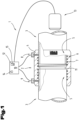
- Fig. 1 shows a first exemplary embodiment of a welding arrangement 1 with a connecting element 2 for connecting line elements 3.
- the connecting element 2 is designed in the form of an electric welding sleeve and the line elements 3 are designed in the form of pipelines.
- the connecting element 2 has a thermoplastic body 4, in which a heating element 6 is arranged in a welding area 5.
- the heating element 6 can in particular be designed in the form of a resistance heating wire 7.
- the connecting element 2 serves to connect two line elements 3 and thus two welding areas 5 are formed in the body 4 of the connecting element 2.
- One of the welding areas 5 serves to weld the connecting element 2 to the first line element 3 and a second of the welding areas 5 serves to weld the connecting element 2 to the second line element 3.
- the heating element 6 has a first connection point 8 and a second connection point 9, each of which is used to connect to a welding device 10.
- the two connection points 8, 9 can, as in Fig. 1 shown, in the area of the two longitudinal ends of the connecting element 2, both welding areas 5 can be heated at the same time by means of the welding device 10.
- the welding areas 5 can be heated in particular by applying an electrical current and an electrical voltage to the first connection point 8 and the second connection point 9 of the heating element 6 using the welding device 10. This and the conductor resistance of the heating element 6 heats up the heating element 6.
- each welding area 5 it is also conceivable for each welding area 5 to have a first connection point 8 and a second connection point 9 for the welding device 10. This makes it possible for each of the two welding areas 5 to be heated individually and independently of one another and for a welded connection to be produced separately between the connecting element 2 and the first line element 3 and between the connecting element 2 and the second line element 3.
- a stop 11 is formed on the body 4 of the connecting element 2, which serves for the correct positioning of the two line elements 3 in the connecting element 2.
- the stop 11 can be formed centrally in the connecting element 2.
- the welding device 10 has a control unit 12, which is used to control the welding process or to control the welding device 10.
- the welding device 10 has an input interface 13, which is coupled to the control unit 12.
- the input interface 13 is used to record information about the connecting element 2 to be welded and/or about the line elements 3 to be welded.
- the input interface 13 is designed as a scanner, which is used to detect a barcode printed on the connecting element 2.
- the welding device 10 can include a display unit 14, which is used to output information to a machine operator.
- the display unit 14 can be coupled to a control panel which is used to operate the welding device 10 by the user.
- a fault counter 15 can be implemented in the control unit 12, which serves to record faults during the welding process.
- the fault counter 15 can be implemented in the programming of the control unit 12.
- thermoplastic line element 3 is connected to the connecting element 2 .
- the line elements 3 are inserted into the connecting element 2. Furthermore, information about the nature of the connecting element 2 is entered into the welding machine 10.
- connection point 8 and the second connection point 9 of the connecting element 2 are connected to the welding device 10, so that the connecting element 2 can be welded to the line element 3.
- the first connection point 8 and the second connection point 9 are supplied with current, so that the resistance heating wire 7 heats up, as a result of which the connecting element 2 is melted in the welding area 5. If the line elements 3 are correctly inserted into the connecting element 2, the connecting element 2 can fuse with the line element 3, whereby a sufficiently tight connection of the line elements 3 to the connecting element 2 is achieved.
- this effect can surprisingly be used to be able to use the welding device 10 to detect whether the welding is being carried out correctly and, if necessary, to stop the welding process and/or to issue an error message from the welding device.
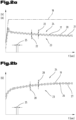
- Fig. 2a the time course of the welding current 17 and the welding voltage 18 is shown.
- the elapsed time in seconds is shown on the abscissa.
- the size of the welding current 17 is shown in amperes on the ordinate.
- the size of the welding voltage 18 is shown in volts on the ordinate.
- Fig. 2a it can be provided that the welding voltage 18 is raised to a certain value when the welding device 10 is activated for welding and is then kept constant at this value.
- the welding current 17 can decrease over the course of the welding process over time, since the heating of the resistance heating wire 7 causes a conductor resistance 19 of the resistance heating wire 7 to increase.
- the course of the welding current 17 as shown in Fig. 2a is shown is the course as it occurs with a correctly welded connecting element 2 and was determined as the actual value 21 of the welding current 17 with a correctly welded connecting element 2.
- the one out Fig. 2a The apparent time course of the welding current 17 can therefore be used as a setpoint 20 of the welding current 17 for a comparable connecting element 2.
- the actual value 21 of the welding current 17 is therefore congruent with the setpoint 20 of the welding current 17.
- the setpoint 20 of the welding current 17 is different for each different version of the connecting element 2.
- welding tests can be carried out with the individual different designs of the connecting element 2.
- the course of the setpoint 20 of the welding current 17 is determined mathematically.
- a setpoint tolerance 22 of the welding current 17 can be calculated, which can be used to check the correct welding.
- the setpoint tolerance 22 of the welding current 17 can be arranged on an underside 23 of the setpoint 20 of the welding current 17 and/or on an upper side 24 of the setpoint 20 of the welding current 17. Deflections of the welding current 17 can thus be detected either only downwards or only upwards or both downwards and upwards.
- the actual value 21 of the welding current 17 can be queried in a query interval 25, with a measurement of the actual value 21 of the welding current 17 being carried out at intervals between the query interval 25.
- Fig. 2b shows the time course of the conductor resistance 19 over the welding process. The elapsed time in seconds is shown on the abscissa. The size of the conductor resistance 19 is shown in ohms on the ordinate. How out Fig. 2b As can be seen, the conductor resistance 19 increases over time.
- the course of the conductor resistance 19 as shown in Fig. 2b is shown is the course as it occurs with a correctly welded connecting element 2 and was determined as the actual value 27 of the conductor resistance 19 with a correctly welded connecting element 2.
- the one out Fig. 2b The apparent time course of the conductor resistance 19 can therefore be used as a setpoint 26 of the conductor resistance 19 for a comparable connecting element 2.
- the actual value 27 of the conductor resistance 19 is therefore congruent with the setpoint 26 of the conductor resistance 19.
- the setpoint 26 of the conductor resistance 19 is different for each different version of the connecting element 2.
- welding tests can be carried out with the individual different designs of the connecting element 2.
- the course of the setpoint 26 of the conductor resistance 19 is determined mathematically.
- a setpoint tolerance 28 of the conductor resistance 19 can be calculated, which can be used to check the correct welding.
- the setpoint tolerance 28 of the conductor resistance 19 can be arranged on an underside 23 of the setpoint 26 of the conductor resistance 19 and/or on an upper side 24 of the setpoint 26 of the conductor resistance 19. Deflections of the conductor resistance 19 can thus be detected either only downwards or only upwards or both downwards and upwards.
- the actual value 27 of the conductor resistance 19 can be queried in a query interval 25, with a measurement of the actual value 27 of the conductor resistance 19 being carried out at the interval of the query interval 25.
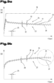
- the actual value 21 of the welding current 17 may increase if two or more turns of the resistance heating wire 7 come into contact with one another and are therefore short-circuited.
- the actual value 21 of the welding current 17 can lie outside the setpoint tolerance 22 of the welding current 17, whereby an error criterion can be determined.
- the actual value 27 of the conductor resistance 19 has the desired value 26 of the conductor resistance on the underside 23 over the course of the welding over time 19 arranged setpoint tolerance 28 is undershot. This can be used as an error criterion to stop the welding process prematurely and/or to issue an error message.
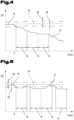
- Fig. 4 shows a detailed view of detail X Fig. 3b , where again for the same elements the same reference numbers or element names as in the previous one Fig. 3b be used. In order to avoid unnecessary repetitions, please refer to the detailed description in the previous section Fig. 3b pointed out or referred to.
- An exemplary embodiment describes how an error criterion for stopping the welding process before the end of the planned welding duration can be defined.
- start event A As soon as the actual value 27 of the conductor resistance 19 falls below the setpoint tolerance 28 of the conductor resistance 19 and this is detected by the welding device 10, this event can be referred to as start event A. From this start event A, a disruption period 16 begins to run.
- a fault message is transmitted to the fault counter 15.
- a second fault period 16 begins to run, with a fault message also being transmitted to the fault counter 15 if the actual value 27 of the conductor resistance 19 falls below the setpoint tolerance 28 of the conductor resistance 19 over the entire fault period 16.
- the error criterion is reached when a certain number of error messages are counted in the error counter 15.
- the present exemplary embodiment according to Fig. 4 For example, there are three fault reports.
- Fig. 5 shows a further process sequence that can occur during a welding process, with the same reference numbers or element names as in the previous one for the same elements Fig. 3b be used. To avoid unnecessary repetitions Please refer to the detailed description in the previous section Fig. 3b pointed out or referred to.
- Fig. 5 As can be seen, if the setpoint tolerance 28 is undershot, the fault period 16 can begin to run. However, if the actual value 27 of the conductor resistance 19 returns within the setpoint tolerance 28 of the conductor resistance 19 within the fault period 16, no error message is sent to the fault counter 15. If the actual value 27 of the conductor resistance 19 falls below the setpoint tolerance 28 of the conductor resistance 19 again, the fault period 16 begins to run again. Since in the present exemplary embodiment the target value tolerance 28 is undershot over the entire fault period 16, an error message is transmitted to the fault counter 15 at the end of the fault period 16. Immediately following this second disruption period 16, a third disruption period 16 begins.
- the fault counter 15 is set to zero again.
- All information on value ranges in this description should be understood to include any and all sub-ranges, e.g. the information 1 to 10 should be understood to include all sub-ranges, starting from the lower limit 1 and the upper limit 10 , i.e. all subranges start with a lower limit of 1 or greater and end with an upper limit of 10 or less, e.g. 1 to 1.7, or 3.2 to 8.1, or 5.5 to 10.
Landscapes
- Engineering & Computer Science (AREA)
- Mechanical Engineering (AREA)
- Physics & Mathematics (AREA)
- Thermal Sciences (AREA)
- General Engineering & Computer Science (AREA)
- Lining Or Joining Of Plastics Or The Like (AREA)
Description
- Die Erfindung betrifft ein Verfahren zum Herstellen einer Schweißverbindung eines Leitungselementes mit einem Verbindungselement.
- Das Verbinden von Leitungselementen aus einem Thermoplast mit Hilfe einer ebenfalls thermoplastischen, mit einem Heizelement versehenen Verbindungselement ist allgemein bekannt. Unter Leitungselementen werden hierbei Rohrleitungsteile, Armaturen und Formstücke verstanden, die durch die Verbindungselemente zu Leitungen und Leitungsnetzen zusammengefügt werden. Die Verbindungselemente sind hierbei häufig als Elektroschweißmuffen und als elektrische schweißbare Anschluss- und Anbohrschellen ausgebildet. Die Verbindungselemente können jedoch auch für das Verbinden anderer Elemente als Rohrleitungselemente verwendet werden, z.B. zum Zusammenfügen von Stangenteilen, doch stellt die Verwendung von schweißbaren Verbindungselementen im Rohrleitungsbau eines der häufigsten Anwendungsgebiete dar. Damit die Verbindung von Leitungselementen mittels solchen Verbindungselementen zuverlässig erfolgt, ist eine Kontrolle der Verschweißung erwünscht. Die
EP0173174A1 geht davon aus, dass die Qualität der Verschweißung im Wesentlichen von der richtigen Temperatur im Schweißbereich und dem beim Schweißvorgang entstehenden Schweißdruck abhängig ist, d.h. von dem Druck, der auf das durch die zugeführte Wärme plastifizierte Material in der Schweißzone ausgeübt wird. Dieser entsteht dadurch, dass dem Verbindungselement eine Schrumpfreserve erteilt wird, die sich beim Plastifizieren des Schweißbereiches durch die zugeführte Wärme in einem Schrumpfen des Verbindungselementes äußert. Dieses Schrumpfen, verbunden mit der Volumenvergrößerung des Materials beim Erwärmen des Schweißbereiches, bewirkt diese Drucksteigerung in dem Schweißbereich. - Da alle Umstände, die das Erreichen der richtigen Schweißtemperatur und des Schweißdruckes verhindern, eine Qualitätsverminderung der Schweißverbindung darstellen, werden schon seit längerer Zeit die Verbindungselemente mit zusätzlichen Anzeigemitteln versehen, welche Rückschlüsse auf die Qualität der Schweißung geben sollen.
- Bei einer bekannten Anzeigevorrichtung wird ein Farbumschlagpunkt verwendet, der auf der äußeren Muffenoberfläche angebracht wird und bei genügender Erwärmung des Körpers des Verbindungselementes seine Farbe wechselt. Damit eine verbesserte Temperaturanzeige erreicht wird, ist es aus der
CH 553 368 - Da die Temperaturanzeige am Verbindungselement allein keine zuverlässigen Rückschlüsse auf die Qualität der Schweißung erlaubt, sind auch Lösungen bekanntgeworden, bei denen der in dem Schweißbereich der Schweißung entstehende Druck sichtbar gemacht wird. Hierbei können Schwachstellen im Körper des Verbindungselementes vorgesehen werden, die sich durch den entstehenden Schweißdruck ausbeulen. Weiter ist aus der
CH 632 078 CH 601 719 - Auch die
EP1745917A1 und dieDE10225370A1 offenbaren jeweils Elektroschweißmuffen für Rohrleitungsverbindungen aus thermoplastischen Kunststoffen, wobei die Elektroschweißmuffe mit einer Rohrleitung mittels eines Elektroschweißverfahrens verbindbar ist. Zum Herstellen der Verbindung wird eine in der Elektroschweißmuffe eingebettete Heizdrahtwicklung mit einer externen elektrischen Stromquelle verbunden, wodurch die Elektroschweißmuffe bereichsweise aufgeschmolzen wird. - Ein weiteres Elektroschweißverfahren zur Verbindung von Rohrleitungen aus thermoplastischen Kunststoffen mittels einer Elektroschweißmuffe ist aus der
JP2000035178A - Aufgabe der vorliegenden Erfindung war es, die Nachteile des Standes der Technik zu überwinden und ein verbessertes Verfahren zum Verschweißen von Verbindungselementen anzugeben.
- Diese Aufgabe wird durch eine Vorrichtung und ein Verfahren gemäß den Ansprüchen gelöst. Erfindungsgemäß ist ein Verfahren zum Verbinden eines thermoplastischen Leitungselementes mit einem Verbindungselement nach Anspruch 1 vorgesehen.
- Vom Schweißgerät wird das Verschweißen des Verbindungselementes mit dem zumindest einen thermoplastischen Leitungselement vor dem Ende der geplanten Schweißdauer gestoppt, wenn ein Fehlerkriterium erreicht wird. Alternativ oder zusätzlich wird vom Schweißgerät eine Fehlermeldung ausgegeben, wenn ein Fehlerkriterium erreicht wird.
- Das erfindungsgemäße Verfahren weist den Vorteil auf, dass durch das Stoppen des Schweißvorganges vor dem Ende der geplanten Schweißdauer bei Erreichen eines Fehlerkriteriums ein lokales Überhitzen des Verbindungselementes und somit eine kritische Situation, wie etwa der Brand eines Verbindungselementes unterbunden werden kann. Somit kann durch die erfindungsgemäßen Maßnahmen überraschenderweise die Sicherheit beim Verbinden von Leitungselementen mit dem Verbindungselement erhöht werden.
- Erfindungsgemäß ist vorgesehen, dass das Fehlerkriterium erreicht wird, wenn in einem im Schweißgerät implementierten Störungszähler eine bestimmte Anzahl an Störungsmeldungen summiert werden. Dies bringt den Vorteil mit sich, dass nicht durch eine einzelne Störungsmeldung, welche beispielsweise durch einen Messfehler auftreten könnte, das Fehlerkriterium erreicht wird, sondern dass das Fehlerkriterium nur dann erreicht wird, wenn aufgrund der erhöhten Anzahl von Störungsmeldungen gesichert ist, dass tatsächlich ein Fehler vorliegt.
- Ferner kann vorgesehen sein, dass dem Störungszähler eine Störungsmeldung addiert wird, wenn über einen Störungszeitraum ein Istwert des Schweißstromes außerhalb einer Sollwerttoleranz eines Sollwertes des Schweißstromes liegt. Dies bringt den überraschenden Vorteil mit sich, dass das Fehlerkriterium einfach erfasst werden kann.
- Darüber hinaus kann vorgesehen sein, dass dem Störungszähler eine Störungsmeldung addiert wird, wenn über einen Störungszeitraum ein Istwert des Leiterwiderstandes des Heizelementes außerhalb einer Sollwerttoleranz eines Sollwertes des Leiterwiderstandes des Heizelementes liegt. Besonders der Leiterwiderstand kann mittels des Schweißgerätes einfach und zuverlässig erfasst werden, wobei über die Erfassung des Leiterwiderstandes überraschenderweise darauf rückgeschlossen werden kann, ob eine korrekte Verschweißung vorliegt und somit ob das Leitungselement korrekt mit dem Verbindungselement gefügt ist.
- Vorteilhaft ist auch eine Ausprägung, gemäß welcher vorgesehen sein kann, dass der Zeitrahmen des Störungszeitraumes in Abhängigkeit von den erfassten Informationen über das zu verschweißende Verbindungselement festgelegt wird. Dies bringt insbesondere den Vorteil mit sich, dass das Abschaltkriterium individuell an das zu verschweißende Verbindungselement angepasst werden kann. Relevante Informationen über das zu verschweißende Verbindungselement können beispielsweise einen Durchmesser bzw. eine Ausgestaltung des Verbindungselementes umfassen. Darüber hinaus können relevante Informationen über das Verbindungselement beispielsweise Informationen über Länge und Durchmesser des Widerstandsheizdrahtes enthalten.
- Gemäß einer Weiterbildung ist es möglich, dass der Zeitrahmen des Störungszeitraumes zwischen 1sec und 40sec, insbesondere zwischen 5sec und 30sec, bevorzugt zwischen 8sec und 12sec festgelegt wird. Besonders innerhalb dieser Grenzen hat sich gezeigt, dass ein überraschend zuverlässiges Abschaltkriterium erreicht werden kann.
- Ferner kann es zweckmäßig sein, wenn die Sollwerttoleranz des Sollwertes des Schweißstromes und/oder die Sollwerttoleranz des Sollwertes des Leiterwiderstandes des Heizelementes in Abhängigkeit von den erfassten Informationen über das zu verschweißende Verbindungselement festgelegt wird. Dies bringt insbesondere den Vorteil mit sich, dass das Abschaltkriterium individuell an das zu verschweißende Verbindungselement angepasst werden kann. Relevante Informationen über das zu verschweißende Verbindungselement können beispielsweise einen Durchmesser bzw. eine Ausgestaltung des Verbindungselementes umfassen. Darüber hinaus können relevante Informationen über das Verbindungselement beispielsweise Informationen über Länge, Durchmesser, sowie den spezifischen Widerstand des Widerstandsheizdrahtes enthalten.
- Darüber hinaus kann vorgesehen sein, dass die Sollwerttoleranz des Sollwertes des Schweißstromes und/oder die Sollwerttoleranz des Sollwertes des Leiterwiderstandes des Heizelementes zwischen 0,1% und 10%, insbesondere zwischen 1% und 5%, bevorzugt zwischen 1,5% und 3% des Betrages des jeweiligen Sollwertes beträgt. Besonders bei einer Toleranzgrenze in diesem Wertebereich hat sich überraschenderweise gezeigt, dass ein zuverlässiges Abschaltkriterium erreicht werden kann.
- Weiters kann vorgesehen sein, dass das Fehlerkriterium erreicht wird, wenn im Störungszählermehr als zwei Störungsmeldungen, insbesondere mehr als zwei Störungsmeldungen, bevorzugt mehr als fünf Störungsmeldungen addiert werden. Besonders innerhalb dieses Toleranzbereichs hat sich überraschenderweise gezeigt, dass ein zuverlässiges Abschaltkriterium erreicht werden kann.
- Gemäß einer besonderen Ausprägung ist es möglich, dass die Sollwerttoleranz des Sollwertes des Leiterwiderstandes des Heizelementes ausschließlich an der Unterseite des Sollwertes des Leiterwiderstandes definiert ist. Die bringt den überraschenden Vorteil mit sich, dass etwaige Messfehler oder sonstige Fehler, welche fälschlicherweise einen erhöhten Leiterwiderstand detektieren, nicht zu einem Auslösekriterium führen.
- Weiters kann vorgesehen sein, dass das Fehlerkriterium erreicht wird, wenn in einem im Schweißgerät implementierten Störungszähler vier Störungsmeldungen summiert werden, wobei dem Störungszähler eine Störungsmeldung addiert wird, wenn über einen Störungszeitraum ein Istwert des Leiterwiderstandes des Heizelementes außerhalb einer Sollwerttoleranz eines Sollwertes des Leiterwiderstandes des Heizelementes liegt, wobei der Zeitrahmen des Störungszeitraumes zwischen 8sec und 12sec festgelegt wird und wobei die Sollwerttoleranz des Sollwertes des Leiterwiderstandes des Heizelementes zwischen 1,5% und 3% des Betrages des jeweiligen Sollwertes beträgt. Eine derartige Kombination der Einzelkriterien bringt den überraschenden Vorteil mit sich, dass zuverlässig ein nicht korrektes Fügen des Leitungselementes und des Verbindungselementes detektiert werden kann und trotzdem keine Fehlinterpretationen bzw. unerwünschte vorzeitige Abschaltungen auftreten. Dieser überraschende technische Effekt tritt nur innerhalb dieser engen Grenzen bzw. in der Kombination der Merkmale auf.
- Entsprechend einer vorteilhaften Weiterbildung kann vorgesehen sein, dass der Istwert des Schweißstromes und/oder der Istwert des Leiterwiderstandes des Heizelementes in einem Abfrageintervall zwischen 0,01 sec und 10sec, insbesondere zwischen 0,1sec und 5sec, bevorzugt zwischen 0,9sec und 1,2sec abgefragt wird. Besonders eine Abfrage des Istwertes in diesem Zeitintervall bringt ein ausreichend repräsentatives Ergebnis über den korrekten Fortschritt der Verschweißung mit sich.
- Erfindungsgemäß ist ein Schweißgerät zum Verschweißen eines thermoplastischen Leitungselementes mit einem Verbindungselement nach Anspruch 11 vorgesehen.
- Das erfindungsgemäße Schweißgerät bringt den Vorteil mit sich, dass die Qualität der Verschweißungen erhöht werden kann.
- Das Eingeben von Informationen über das zu verschweißende Verbindungselement in das Schweißgerät kann durch manuelle Eingabe durch einen Maschinenbediener erfolgen. Alternativ dazu ist es auch denkbar, dass das Eingeben von Informationen über das zu verschweißende Verbindungselement in das Schweißgerät durch Erfassen eines am Verbindungselement angebrachten Informationsträgers, wie etwa einem RFID-Chip, oder einem Barcode mittels des Schweißgerätes erfolgt. In wieder einer anderen Alternative ist es auch denkbar, dass das Eingeben von Informationen über das zu verschweißende Verbindungselement in das Schweißgerät durch Erfassen des Leiterwiderstandes mittels des Schweißgerätes erfolgt.
- In einer weiteren Ausführungsvariante ist es auch denkbar, dass das Schweißgerät nur zum Verschweißen von einer Type von Verbindungselementen ausgebildet ist. In diesem Fall wird die Informationen über das zu verschweißende Verbindungselement direkt vom Hersteller in das Schweißgerät eingegeben und braucht nicht bei jedem Schweißvorgang gesondert erfasst zu werden.
- Insbesondere ist am Schweißgerät ein Eingabeinterface vorgesehen, mittels welchem die Informationen über das zu verschweißende Verbindungselement in das Schweißgerät eingegeben werden kann. Das Eingabeinterface kann beispielsweise eine Tastatur, ein RFID-Leser, ein Barcodeleser oder dergleichen sein.
- Zum besseren Verständnis der Erfindung wird diese anhand der nachfolgenden Figuren näher erläutert.
- Es zeigen jeweils in stark vereinfachter, schematischer Darstellung:
- Fig. 1
- eine Schnittdarstellung eines Ausführungsbeispiels eines Verbindungselementes einer Schweißanordnung;
- Fig. 2
- a) eine schematische Darstellung des zeitlichen Verlaufs des Stromes und der Spannung während dem Schweißvorgang einer korrekt durchgeführten Verschweißung;
- Fig. 2
- b) eine schematische Darstellung des zeitlichen Verlaufs des Innenwiderstandes des Widerstandsheizdrahtes während dem Schweißvorgang einer korrekt durchgeführten Verschweißung;
- Fig. 3
- a) eine schematische Darstellung des zeitlichen Verlaufs des Stromes und der Spannung während dem Schweißvorgang einer fehlerhaft durchgeführten Verschweißung;
- Fig. 3
- b) eine schematische Darstellung des zeitlichen Verlaufs des Innenwiderstandes des Widerstandsheizdrahtes während dem Schweißvorgang einer fehlerhaft durchgeführten Verschweißung;
- Fig. 4
- eine Detailansicht eines ersten Ausführungsbeispiels zur Erreichung eines Abschaltkriteriums;
- Fig. 5
- eine Detailansicht eines zweiten Ausführungsbeispiels zur Erreichung eines Abschaltkriteriums.
- Einführend sei festgehalten, dass in den unterschiedlich beschriebenen Ausführungsformen gleiche Teile mit gleichen Bezugszeichen bzw. gleichen Bauteilbezeichnungen versehen werden, wobei die in der gesamten Beschreibung enthaltenen Offenbarungen sinngemäß auf gleiche Teile mit gleichen Bezugszeichen bzw. gleichen Bauteilbezeichnungen übertragen werden können. Auch sind die in der Beschreibung gewählten Lageangaben, wie z.B. oben, unten, seitlich usw. auf die unmittelbar beschriebene sowie dargestellte Figur bezogen und sind diese Lageangaben bei einer Lageänderung sinngemäß auf die neue Lage zu übertragen.
-
Fig. 1 zeigt ein erstes Ausführungsbeispiel einer Schweißanordnung 1 mit einem Verbindungselement 2 zum Verbinden von Leitungselementen 3. - Im Ausführungsbeispiel nach
Fig. 1 ist das Verbindungselement 2 in Form einer Elektroschweißmuffe ausgebildet und die Leitungselemente 3 sind in Form von Rohrleitungen ausgebildet. - Wie aus
Fig. 1 ersichtlich, kann vorgesehen sein, dass das Verbindungselement 2 einen thermoplastischen Körper 4 aufweist, in welchem in einem Schweißbereich 5 ein Heizelement 6 angeordnet ist. Das Heizelement 6 kann insbesondere in Form eines Widerstandsheizdrahtes 7 ausgebildet sein. - Beispielsweise ist es denkbar, dass das Verbindungselement 2 zum Verbinden von zwei Leitungselementen 3 dient und somit im Körper 4 des Verbindungselementes 2 zwei Schweißbereiche 5 ausgebildet sind.
- Einer der Schweißbereiche 5 dient hierbei zum Verschweißen des Verbindungselementes 2 mit dem ersten Leitungselement 3 und ein zweiter der Schweißbereiche 5 dient hierbei zum Verschweißen des Verbindungselementes 2 mit dem zweiten Leitungselement 3.
- Wie aus
Fig. 1 weiters ersichtlich, kann vorgesehen sein, dass das Heizelement 6 einen ersten Anschlusspunkt 8 und einen zweiten Anschlusspunkt 9 aufweist, welcher jeweils zum Verbinden mit einem Schweißgerät 10 dienen. Die beiden Anschlusspunkte 8, 9 können, wie inFig. 1 dargestellt, im Bereich der beiden Längsenden des Verbindungselementes 2 ausgebildet sein, wobei mittels des Schweißgerätes 10 beide Schweißbereiche 5 gleichzeitig erhitzt werden können. Die Schweißbereiche 5 können insbesondere dadurch erhitzt werden, dass mittels des Schweißgerätes 10 ein elektrischer Strom und eine elektrische Spannung an den ersten Anschlusspunkt 8 und den zweiten Anschlusspunkt 9 des Heizelementes 6 angelegt wird. Dadurch und durch den Leiterwiderstand des Heizelementes 6 erhitzt sich das Heizelement 6. - Weiters ist es auch denkbar, dass je Schweißbereich 5 ein erster Anschlusspunkt 8 und ein zweiter Anschlusspunkt 9 für das Schweißgerät 10 ausgebildet sind. Dadurch wird ermöglicht, dass jeder der beiden Schweißbereiche 5 einzeln und unabhängig voneinander erhitzt werden kann und zwischen dem Verbindungselement 2 und dem ersten Leitungselement 3 sowie und zwischen dem Verbindungselement 2 und dem zweiten Leitungselement 3 gesondert eine Schweißverbindung hergestellt werden kann.
- Wie aus
Fig. 1 weiters ersichtlich, kann vorgesehen sein, dass am Körper 4 des Verbindungselementes 2 ein Anschlag 11 ausgebildet ist, welcher zur korrekten Positionierung der beiden Leitungselemente 3 im Verbindungselement 2 dient. Der Anschlag 11 kann zentral im Verbindungselement 2 ausgebildet sein. - Wie aus
Fig. 1 weiters ersichtlich, weist das Schweißgerät 10 eine Steuereinheit 12 auf, welche zur Steuerung des Schweißvorganges bzw. zur Steuerung des Schweißgeräts 10 dient. - Weiters weißt das Schweißgerät 10 ein Eingabeinterface 13 auf, welches mit der Steuereinheit 12 gekoppelt ist. Das Eingabeinterface 13 dient zum Erfassen von Informationen über das zu verschweißende Verbindungselement 2 und/oder über die zu verschweißenden Leitungselemente 3. Im Ausführungsbeispiel nach
Fig. 1 ist das Eingabeinterface 13 als Scanner ausgebildet, welcher zum Erfassen eines auf das Verbindungselement 2 aufgedruckten Barcodes dient. - Zusätzlich kann das Schweißgerät 10 eine Anzeigeeinheit 14 umfassen, welche zur Ausgabe von Informationen an einen Maschinenbediener dient. Die Anzeigeeinheit 14 kann mit einem Bedienfeld gekoppelt sein, welches zur Bedienung des Schweißgerätes 10 durch den Benutzer dient.
- Weiters kann in der Steuereinheit 12 ein Störungszähler 15 realisiert sein, welcher zur Erfassung von Störungen während dem Schweißvorgang dient. Der Störungszähler 15 kann in der Programmierung der Steuereinheit 12 realisiert sein.
- In weiterer Folge wird anhand der
Fig. 1 der Schweißvorgang zum Verbinden des thermoplastischen Leitungselementes 3 mit dem Verbindungselement 2 beschrieben. - Zum Verschweißen des Verbindungselementes 2 mit den Leitungselementen 3, werden die Leitungselemente 3 in das Verbindungselement 2 eingesteckt. Weiters werden in das Schweißgerät 10 Informationen zur Beschaffenheit des Verbindungselementes 2 eingegeben.
- Weiters wird der erste Anschlusspunkt 8 und der zweite Anschlusspunkt 9 des Verbindungselementes 2 mit dem Schweißgerät 10 verbunden, sodass eine Verschweißung des Verbindungselementes 2 mit dem Leitungselement 3 ermöglicht wird.
- Beim Schweißvorgang an sich wird der erste Anschlusspunkt 8 und der zweite Anschlusspunkt 9 mit Strom beaufschlagt, sodass sich der Widerstandsheizdraht 7 erhitzt, wodurch das Verbindungselement 2 im Schweißbereich 5 aufgeschmolzen wird. Wenn die Leitungselemente 3 korrekt in das Verbindungselement 2 eingesteckt sind, kann das Verbindungselement 2 mit dem Leitungselement 3 verschmelzen, wodurch eine ausreichend dichte Verbindung der Leitungselemente 3 mit dem Verbindungselement 2 erreicht wird.
- Wenn, wie in
Fig. 1 am rechten Leitungselement 3 dargestellt, das Leitungselement 3 nicht korrekt in das Verbindungselement 2 eingesteckt ist, kann dies dazu führen, dass jener Abschnitt des Schweißbereiches 5 des Verbindungselementes 2, an welchem das Leitungselement 3 nicht anliegt, durch die fehlende Wärmeabfuhr unkontrolliert aufschmilzt. Dadurch kann es in diesem Bereich zu unkontrollierten Austritten des Materials des Verbindungselementes 2 kommen. - Durch diesen Austritt von Material des Verbindungselementes 2 kann darüber hinaus vorkommen, dass zwei Wicklungen des Widerstandsheizdrahtes 7 durch die entstehenden Verschiebungen einander kontaktieren, wodurch die Wicklungsschlaufe dieser beiden nebeneinander liegenden Wicklungen des Widerstandsheizdrahtes 7 kurzgeschlossen und somit überbrückt wird. Durch das erfindungsgemäße Verfahren kann dieser Effekt überraschenderweise dazu genutzt werden, um mittels dem Schweißgerät 10 detektieren zu können, ob die Verschweißung korrekt durchgeführt wird und gegebenenfalls den Schweißvorgang zu stoppen und/oder vom Schweißgerät eine Fehlermeldung auszugeben.
- In der
Fig. 2a ist der zeitliche Verlauf des Schweißstromes 17 und der Schweißspannung 18 dargestellt. Die vergangene Zeit in Sekunden ist hierbei auf der Abszisse dargestellt. Die Größe des Schweißstromes 17 ist in Ampere auf der Ordinate dargestellt. Die Größe der der Schweißspannung 18 ist in Volt auf der Ordinate dargestellt. - Wie aus
Fig. 2a ersichtlich, kann vorgesehen sein, dass die Schweißspannung 18 beim Aktivieren des Schweißgerätes 10 zur Verschweißung auf einen bestimmten Wert angehoben wird und anschließend konstant auf diesen Wert gehalten wird. Der Schweißstrom 17 kann über den zeitlichen Verlauf des Verschweißvorganges gesehen abfallen, da durch die Erhitzung des Widerstandsheizdrahtes 7 ein Leiterwiderstand 19 des Widerstandsheizdrahtes 7 ansteigt. - Der Verlauf des Schweißstromes 17 wie er in
Fig. 2a dargestellt ist, ist jener Verlauf wie er bei einem korrekt verschweißten Verbindungselement 2 auftritt und als Istwert 21 des Schweißstromes 17 bei einem korrekt verschweißten Verbindungselement 2 ermittelt wurde. Der ausFig. 2a ersichtliche zeitliche Verlauf des Schweißstromes 17 kann somit als Sollwert 20 des Schweißstromes 17 für ein vergleichbares Verbindungselement 2 herangezogen werden. In der vorliegenden Darstellung nachFig. 2a ist somit der Istwert 21 des Schweißstromes 17 deckungsgleich mit dem Sollwert 20 des Schweißstromes 17. - Der Sollwert 20 des Schweißstromes 17 ist für jede unterschiedliche Ausführung des Verbindungselementes 2 jedoch unterschiedlich. Zur Ermittlung des Sollwertes 20 des Schweißstromes 17 können Schweißversuche mit den einzelnen unterschiedlichen Ausführungen des Verbindungselementes 2 durchgeführt werden. Alternativ dazu ist es auch denkbar, dass der Verlauf des Sollwertes 20 des Schweißstroms 17 rechnerisch ermittelt wird.
- Aus dem Sollwert 20 des Schweißstromes 17 kann eine Sollwerttoleranz 22 des Schweißstromes 17 berechnet werden, welche zur Kontrolle der korrekten Verschweißung dienen kann. Die Sollwerttoleranz 22 des Schweißstromes 17 kann an einer Unterseite 23 des Sollwertes 20 des Schweißstromes 17 und/oder an einer Oberseite 24 des Sollwertes 20 des Schweißstromes 17 angeordnet sein. Somit können Ausschläge des Schweißstromes 17 entweder nur nach unten oder nur nach oben oder sowohl nach unten als auch nach oben erfasst werden.
- Der Istwert 21 des Schweißstromes 17 kann in einem Abfrageintervall 25 abgefragt werden, wobei im Abstand des Abfrageintervalls 25 eine Messung des Istwertes 21 des Schweißstromes 17 durchgeführt wird.
-
Fig. 2b zeigt den zeitlichen Verlauf des Leiterwiderstandes 19 über den Schweißvorgang. Die vergangene Zeit in Sekunden ist hierbei auf der Abszisse dargestellt. Die Größe des Leiterwiderstandes 19 ist in Ohm auf der Ordinate dargestellt. Wie ausFig. 2b ersichtlich, steigt der Leiterwiderstand 19 über den zeitlichen Verlauf an. - Der Verlauf des Leiterwiderstandes 19 wie er in
Fig. 2b dargestellt ist, ist jener Verlauf wie er bei einem korrekt verschweißten Verbindungselement 2 auftritt und als Istwert 27 des Leiterwiderstandes 19 bei einem korrekt verschweißten Verbindungselement 2 ermittelt wurde. Der ausFig. 2b ersichtliche zeitliche Verlauf des Leiterwiderstandes 19 kann somit als Sollwert 26 des Leiterwiderstandes 19 für ein vergleichbares Verbindungselement 2 herangezogen werden. In der vorliegenden Darstellung nachFig. 2b ist somit der Istwert 27 des Leiterwiderstandes 19 deckungsgleich mit dem Sollwert 26 des Leiterwiderstandes 19. - Wie aus
Fig. 2b ersichtlich, steigt der Istwert 27 des Leiterwiderstandes 19 über den Zeitlichen Verlauf mit fortschreitender Erwärmung des Widerstandsheizdrahtes 7 an. - Der Sollwert 26 des Leiterwiderstandes 19 ist für jede unterschiedliche Ausführung des Verbindungselementes 2 jedoch unterschiedlich. Zur Ermittlung des Sollwertes 26 des Leiterwiderstandes 19 können Schweißversuche mit den einzelnen unterschiedlichen Ausführungen des Verbindungselementes 2 durchgeführt werden. Alternativ dazu ist es auch denkbar, dass der Verlauf des Sollwertes 26 des Leiterwiderstandes 19 rechnerisch ermittelt wird.
- Aus dem Sollwert 26 des Leiterwiderstandes 19 kann eine Sollwerttoleranz 28 des Leiterwiderstandes 19 berechnet werden, welche zur Kontrolle der korrekten Verschweißung dienen kann. Die Sollwerttoleranz 28 des Leiterwiderstandes 19 kann an einer Unterseite 23 des Sollwertes 26 des Leiterwiderstandes 19 und/oder an einer Oberseite 24 des Sollwertes 26 des Leiterwiderstandes 19 angeordnet sein. Somit können Ausschläge des Leiterwiderstandes 19 entweder nur nach unten oder nur nach oben oder sowohl nach unten als auch nach oben erfasst werden.
- Der Istwert 27 des Leiterwiderstandes 19 kann in einem Abfrageintervall 25 abgefragt werden, wobei im Abstand des Abfrageintervalls 25 eine Messung des Istwertes 27 des Leiterwiderstandes 19 durchgeführt wird.
- In der
Fig. 3a ist der zeitliche Verlauf des Schweißstromes 17 bei einem nicht korrekt verbundenen Verbindungselement 2 dargestellt, wobei wiederum für gleiche Elemente gleiche Bezugszeichen bzw. Elementbezeichnungen wie in der vorangegangenenFig. 2a verwendet werden. Um unnötige Wiederholungen zu vermeiden, wird auf die detaillierte Beschreibung in der vorangegangenenFig. 2a hingewiesen bzw. Bezug genommen. - Wie aus
Fig. 3a ersichtlich, kann es bei einem nicht korrekt verbunden Verbindungselement 2 dazu kommen, dass der Istwert 21 des Schweißstromes 17 ansteigt, wenn zwei oder mehrere Windungen des Widerstandsheizdrahtes 7 miteinander in Berührung kommen und somit kurzgeschlossen werden. Der Istwert 21 des Schweißstromes 17 kann hierbei außerhalb der Sollwerttoleranz 22 des Schweißstromes 17 liegen, wodurch ein Fehlerkriterium ermittelt werden kann. - In der
Fig. 3a ist der zeitliche Verlauf des Schweißstromes 17 bei einem nicht korrekt verbundenen Verbindungselement 2 dargestellt, wobei wiederum für gleiche Elemente gleiche Bezugszeichen bzw. Elementbezeichnungen wie in der vorangegangenenFig. 2a verwendet werden. Um unnötige Wiederholungen zu vermeiden, wird auf die detaillierte Beschreibung in der vorangegangenenFig. 2a hingewiesen bzw. Bezug genommen. - In
Fig. 3b ist der korrespondierende Verlauf des Istwertes 27 des Leiterwiderstandes 19 eines nicht korrekt verschweißten Verbindungselementes 2 dargestellt, wobei wiederum für gleiche Elemente gleiche Bezugszeichen bzw. Elementbezeichnungen wie in der vorangegangenenFig. 2b verwendet werden. Um unnötige Wiederholungen zu vermeiden, wird auf die detaillierte Beschreibung in der vorangegangenenFig. 2b hingewiesen bzw. Bezug genommen. - Wie aus
Fig. 3b ersichtlich, hat über den zeitlichen Verlauf der Verschweißung der Istwert 27 des Leiterwiderstandes 19 die an der Unterseite 23 des Sollwertes 26 des Leiterwiderstandes 19 angeordnete Sollwerttoleranz 28 unterschritten. Dies kann als Fehlerkriterium herangezogen werden, um den Schweißprozess vorzeitig zu stoppen und/oder eine Fehlermeldung auszugeben. -
Fig. 4 zeigt eine Detailansicht des Details X ausFig. 3b , wobei wiederum für gleiche Elemente gleiche Bezugszeichen bzw. Elementbezeichnungen wie in der vorangegangenenFig. 3b verwendet werden. Um unnötige Wiederholungen zu vermeiden, wird auf die detaillierte Beschreibung in der vorangegangenenFig. 3b hingewiesen bzw. Bezug genommen. - Anhand der
Fig. 4 wird ein Ausführungsbeispiel beschrieben, wie ein Fehlerkriterium zum Stoppen des Schweißvorganges vor dem Ende der geplanten Schweißdauer definiert werden kann. - Sobald der Istwert 27 des Leiterwiderstandes 19 unter die Sollwerttoleranz 28 des Leiterwiderstandes 19 abfällt und dies vom Schweißgerät 10 detektiert wird, kann dieses Ereignis als Startereignis A bezeichnet werden. Ab diesem Startereignis A beginnt ein Störungszeitraum 16 zu laufen.
- Wenn nun der Istwert 27 des Leiterwiderstandes 19 über den kompletten Störungszeitraum 16 hinaus außerhalb der Sollwerttoleranz 28 des Leiterwiderstandes 19 liegt, so wird dem Störungszähler 15 eine Störungsmeldung übermittelt. Am Ende des ersten Störungszeitraums 16 beginnt ein zweiter Störungszeitraum 16 zu laufen, wobei ebenfalls eine Störungsmeldung an den Störungszähler 15 übermittelt wird, wenn über den gesamten Störungszeitraum 16 die Sollwerttoleranz 28 des Leiterwiderstandes 19 vom Istwert 27 des Leiterwiderstandes 19 unterschritten wird.
- Insbesondere kann festgelegt sein, dass das Fehlerkriterium erreicht wird, wenn im Störungszähler 15 eine gewisse Anzahl an Störungsmeldungen gezählt werden. Im vorliegenden Ausführungsbeispiel nach
Fig. 4 liegen beispielsweise drei Störungsmeldungen vor. -
Fig. 5 zeigt einen weiteren Verfahrensablauf, welcher bei einem Schweißvorgang auftreten kann, wobei wiederum für gleiche Elemente gleiche Bezugszeichen bzw. Elementbezeichnungen wie in der vorangegangenenFig. 3b verwendet werden. Um unnötige Wiederholungen zu vermeiden, wird auf die detaillierte Beschreibung in der vorangegangenenFig. 3b hingewiesen bzw. Bezug genommen. - Wie aus
Fig. 5 ersichtlich, kann bei Unterschreiten der Sollwerttoleranz 28 der Störungszeitraum 16 zu laufen beginnen. Wenn allerdings innerhalb des Störungszeitraumes 16 der Istwert 27 des Leiterwiderstandes 19 innerhalb die Sollwerttoleranz 28 des Leiterwiderstandes 19 zurückkehrt, so wird keine Fehlermeldung an den Störungszähler 15 abgegeben. Bei einem erneuten Unterschreiten der Sollwerttoleranz 28 des Leiterwiderstandes 19 vom Istwert 27 des Leiterwiderstandes 19 beginnt der Störungszeitraum 16 von neuem zu Laufen. Da im vorliegenden Ausführungsbeispiel über den kompletten Störungszeitraum 16 hinweg ein Unterschreiten der Sollwerttoleranz 28 vorliegt, wird am Ende des Störungszeitraums 16 dem Störungszähler 15 eine Fehlermeldung übermittelt. Unmittelbar an diesen zweiten Störungszeitraum 16 anschließend beginnt ein dritter Störungszeitraum 16 zu laufen. Da allerdings nicht über den kompletten dritten Störungszeitraum 16 hinweg die Sollwerttoleranz 28 des Leiterwiderstandes 19 unterschritten wird, wird auch hier keine Störungsmeldung an den Störungszähler 15 ausgegeben. Bei einem erneuten Unterschreiten der Sollwerttoleranz 28 beginnt der Störungszeitraum 16 erneut zu laufen. Da im vorliegenden Ausführungsbeispiel der Istwert 27 des Leiterwiderstandes 19 über den kompletten Störungszeitraum 16 hinweg die Sollwerttoleranz 28 des Leiterwiderstandes 19 unterschreitet, wird in diesem Fall im Störungszähler 15 eine weitere Störungsmeldung generiert. Im vorliegenden Ausführungsbeispiel nachFig. 5 sind somit im sichtbaren Ausschnittdetail zwei Störungsmeldungen an den Störungszähler 15 übermittelt worden. Als Fehlerkriterium kann festgelegt sein, dass der Schweißprozess gestoppt wird, wenn im Störungszähler 15 zwei Störungsmeldungen gezählt werden, was im vorliegenden Ausführungsbeispiel dazu führen würde, dass am Ende des vierten Störungszeitraums 16 das Fehlerkriterium erreicht wird. - Bei jedem Neustart eines Schweißprozesses kann vorgesehen sein, dass der Störungszähler 15 wieder auf null gesetzt wird.
- Die in den
Fig. 4 und 5 beschriebenen Vorgänge können natürlich mutatis mutandis auch bei der Erfassung des Istwertes 21 des Schweißstromes 17 angewandt werden. - Die Ausführungsbeispiele zeigen mögliche Ausführungsvarianten, wobei an dieser Stelle bemerkt sei, dass die Erfindung nicht auf die speziell dargestellten Ausführungsvarianten derselben eingeschränkt ist, sondern vielmehr auch diverse Kombinationen der einzelnen Ausführungsvarianten untereinander möglich sind und diese Variationsmöglichkeit aufgrund der Lehre zum technischen Handeln durch gegenständliche Erfindung im Können des auf diesem technischen Gebiet tätigen Fachmannes liegt.
- Der Schutzbereich ist durch die Ansprüche bestimmt. Die Beschreibung und die Zeichnungen sind jedoch zur Auslegung der Ansprüche heranzuziehen. Einzelmerkmale oder Merkmalskombinationen aus den gezeigten und beschriebenen unterschiedlichen Ausführungsbeispielen können für sich eigenständige erfinderische Lösungen darstellen. Die den eigenständigen erfinderischen Lösungen zugrundeliegende Aufgabe kann der Beschreibung entnommen werden.
- Sämtliche Angaben zu Wertebereichen in gegenständlicher Beschreibung sind so zu verstehen, dass diese beliebige und alle Teilbereiche daraus mitumfassen, z.B. ist die Angabe 1 bis 10 so zu verstehen, dass sämtliche Teilbereiche, ausgehend von der unteren Grenze 1 und der oberen Grenze 10 mit umfasst sind, d.h. sämtliche Teilbereiche beginnen mit einer unteren Grenze von 1 oder größer und enden bei einer oberen Grenze von 10 oder weniger, z.B. 1 bis 1,7, oder 3,2 bis 8,1, oder 5,5 bis 10.
- Der Ordnung halber sei abschließend darauf hingewiesen, dass zum besseren Verständnis des Aufbaus Elemente teilweise unmaßstäblich und/oder vergrößert und/oder verkleinert dargestellt wurden.
-
- 1
- Schweißanordnung
- 2
- Verbindungselement
- 3
- Leitungselement
- 4
- Körper
- 5
- Schweißbereich
- 6
- Heizelement
- 7
- Widerstandsheizdraht
- 8
- erster Anschlusspunkt
- 9
- zweiter Anschlusspunkt
- 10
- Schweißgerät
- 11
- Anschlag
- 12
- Steuereinheit
- 13
- Eingabeinterface
- 14
- Anzeigeeinheit
- 15
- Störungszähler
- 16
- Störungszeitraum
- 17
- Schweißstrom
- 18
- Schweißspannung
- 19
- Leiterwiderstand
- 20
- Sollwert Schweißstrom
- 21
- Istwert Schweißstrom
- 22
- Sollwerttoleranz Schweißstrom
- 23
- Unterseite Sollwert
- 24
- Oberseite Sollwert
- 25
- Abfrageintervall
- 26
- Sollwert Leiterwiderstand
- 27
- Istwert Leiterwiderstand
- 28
- Sollwerttoleranz Leiterwiderstand
Claims (11)
- Verfahren zum Verbinden eines thermoplastischen Leitungselementes (3) mit einem Verbindungselement (2) umfassend die Verfahrensschritte:- Bereitstellen des zumindest einen thermoplastischen Leitungselementes (3);- Bereitstellen des Verbindungselementes (2), welches einen thermoplastischen Körper (4) aufweist, wobei ein Heizelement (6) im Körper (4) eingebettet ist, welches in einem Schweißbereich (5) zur Erzeugung von Wärme zur Verschweißung des Körpers (4) mit dem zumindest einen Leitungselement (3) dient;- Fügen des Verbindungselementes (2) mit dem zumindest einen thermoplastischen Leitungselement (3);- Bereitstellen eines Schweißgerätes (10) zum Verschweißen des Verbindungselementes (2) mit dem zumindest einen thermoplastischen Leitungselement (3);- Eingeben von Informationen über das zu verschweißende Verbindungselement (2) in das Schweißgerät (10);- Verschweißen des Verbindungselementes (2) mit dem zumindest einen thermoplastischen Leitungselement (3) durch Erzeugung von Wärme im Schweißbereich (5) mittels des Schweißgerätes (10),wobei
vom Schweißgerät (10) das Verschweißen des Verbindungselementes (2) mit dem zumindest einen thermoplastischen Leitungselement (3) vor dem Ende der geplanten Schweißdauer gestoppt wird und/oder vom Schweißgerät (10) eine Fehlermeldung ausgegeben wird, wenn ein Fehlerkriterium erreicht wird, dadurch gekennzeichnet, dass das Fehlerkriterium erreicht wird, wenn in einem im Schweißgerät (10) implementierten Störungszähler (15) eine bestimmte Anzahl an Störungsmeldungen summiert werden. - Verfahren nach Anspruch 1, dadurch gekennzeichnet, dass dem Störungszähler (15) eine Störungsmeldung addiert wird, wenn über einen Störungszeitraum (16) ein Istwert (21) des Schweißstromes (17) außerhalb einer Sollwerttoleranz (22) eines Sollwertes (20) des Schweißstromes (17) liegt.
- Verfahren nach Anspruch 1 oder 2, dadurch gekennzeichnet, dass dem Störungszähler (15) eine Störungsmeldung addiert wird, wenn über einen Störungszeitraum (16) ein Istwert (27) des Leiterwiderstandes (19) des Heizelementes (6) außerhalb einer Sollwerttoleranz (28) eines Sollwertes (26) des Leiterwiderstandes (19) des Heizelementes (6) liegt.
- Verfahren nach Anspruch 2 oder 3, dadurch gekennzeichnet, dass der Zeitrahmen des Störungszeitraumes (16) in Abhängigkeit von den erfassten Informationen über das zu verschweißende Verbindungselement (2) festgelegt wird.
- Verfahren nach einem der Ansprüche 2 bis 4, dadurch gekennzeichnet, dass der Zeitrahmen des Störungszeitraumes (16) zwischen 1sec und 40sec, insbesondere zwischen 5sec und 30sec, bevorzugt zwischen 8sec und 12sec festgelegt wird.
- Verfahren nach einem der Ansprüche 2 bis 5, dadurch gekennzeichnet, dass die Sollwerttoleranz (22) des Sollwertes (20) des Schweißstromes (17) und/oder die Sollwerttoleranz (28) des Sollwertes (26) des Leiterwiderstandes (19) des Heizelementes (6) in Abhängigkeit von den erfassten Informationen über das zu verschweißende Verbindungselement (2) festgelegt wird.
- Verfahren nach einem der Ansprüche 2 bis 6, dadurch gekennzeichnet, dass die Sollwerttoleranz (22) des Sollwertes (20) des Schweißstromes (17) und/oder die Sollwerttoleranz (28) des Sollwertes (26) des Leiterwiderstandes (19) des Heizelementes (6) zwischen 0,1% und 10%, insbesondere zwischen 1% und 5%, bevorzugt zwischen 1,5% und 3% des Betrages des jeweiligen Sollwertes (20, 26) beträgt.
- Verfahren nach einem der Ansprüche 1 bis 7, dadurch gekennzeichnet, dass das Fehlerkriterium erreicht wird, wenn im Störungszähler (15) mehr als zwei Störungsmeldungen, insbesondere mehr als drei Störungsmeldungen, bevorzugt mehr als fünf Störungsmeldungen addiert werden.
- Verfahren nach einem der Ansprüche 2 bis 8, dadurch gekennzeichnet, dass die Sollwerttoleranz (28) des Sollwertes (26) des Leiterwiderstandes (19) des Heizelementes (6) ausschließlich an der Unterseite (23) des Sollwertes (26) des Leiterwiderstandes (19) definiert ist.
- Verfahren nach einem der vorhergehenden Ansprüche, dadurch gekennzeichnet, dass das Fehlerkriterium erreicht wird, wenn in einem im Schweißgerät (10) implementierten Störungszähler (15) vier Störungsmeldungen summiert werden, wobei dem Störungszähler (15) eine Störungsmeldung addiert wird, wenn über einen Störungszeitraum (16) ein Istwert (27) des Leiterwiderstandes (19) des Heizelementes (6) außerhalb einer Sollwerttoleranz (28) eines Sollwertes (26) des Leiterwiderstandes (19) des Heizelementes (6) liegt, wobei der Zeitrahmen des Störungszeitraumes (16) zwischen 8sec und 12sec festgelegt wird und wobei die Sollwerttoleranz (28) des Sollwertes (26) des Leiterwiderstandes (19) des Heizelementes (6) zwischen 1,5% und 3% des Betrages des jeweiligen Sollwertes (26) beträgt.
- Schweißgerät (10) zum Verschweißen eines thermoplastischen Leitungselementes (3) mit einem Verbindungselement (2), wobei das Schweißgerät eine Steuereinheit (12) und ein Eingabeinterface (13) zum Eingeben von Informationen über das zu verschweißende Verbindungselement (2) aufweist, wobei das Eingabeinterface (13) mit der Steuereinheit (12) gekoppelt ist, wobei das Schweißgerät (10) derart ausgebildet ist, dass das Verschweißen des Verbindungselementes (2) mit dem zumindest einen thermoplastischen Leitungselement (3) vor dem Ende der geplanten Schweißdauer stoppbar ist und/oder vom Schweißgerät (10) eine Fehlermeldung ausgebbar ist, wenn ein Fehlerkriterium erreicht wird, dadurch gekennzeichnet, dass im Schweißgerät (10) ein Störungszähler (15) implementiert ist, wobei das Schweißgerät (10) derart konfiguriert ist, dass das Fehlerkriterium erreicht wird, wenn eine bestimmte Anzahl an Störungsmeldungen summiert werden.
Priority Applications (1)
| Application Number | Priority Date | Filing Date | Title |
|---|---|---|---|
| HRP20240786TT HRP20240786T1 (hr) | 2019-05-22 | 2019-05-22 | Postupak stvaranja zavara i uređaj za zavarivanje |
Applications Claiming Priority (1)
| Application Number | Priority Date | Filing Date | Title |
|---|---|---|---|
| PCT/AT2019/060169 WO2020232479A1 (de) | 2019-05-22 | 2019-05-22 | VERFAHREN ZUM HERSTELLEN EINER SCHWEIßVERBINDUNG SOWIE SCHWEIßGERÄT |
Publications (3)
| Publication Number | Publication Date |
|---|---|
| EP3840941A1 EP3840941A1 (de) | 2021-06-30 |
| EP3840941B1 true EP3840941B1 (de) | 2024-03-13 |
| EP3840941C0 EP3840941C0 (de) | 2024-03-13 |
Family
ID=67107310
Family Applications (1)
| Application Number | Title | Priority Date | Filing Date |
|---|---|---|---|
| EP19734229.8A Active EP3840941B1 (de) | 2019-05-22 | 2019-05-22 | Verfahren zum herstellen einer schweissverbindung sowie schweissgerät |
Country Status (10)
| Country | Link |
|---|---|
| US (1) | US11987010B2 (de) |
| EP (1) | EP3840941B1 (de) |
| JP (1) | JP7497347B2 (de) |
| KR (1) | KR102500263B1 (de) |
| CN (1) | CN112912234A (de) |
| AU (1) | AU2019446744B2 (de) |
| ES (1) | ES2980150T3 (de) |
| HR (1) | HRP20240786T1 (de) |
| PL (1) | PL3840941T3 (de) |
| WO (1) | WO2020232479A1 (de) |
Families Citing this family (1)
| Publication number | Priority date | Publication date | Assignee | Title |
|---|---|---|---|---|
| IT202300009684A1 (it) * | 2023-05-15 | 2024-11-15 | Sigam Logistics S R L | Pallet plastico e relativo sistema di produzione |
Citations (21)
| Publication number | Priority date | Publication date | Assignee | Title |
|---|---|---|---|---|
| CH553368A (de) | 1973-03-14 | 1974-08-30 | Sturm Werner | Muffe aus thermoplastischem kunststoff. |
| CH601719A5 (en) | 1977-02-25 | 1978-07-14 | Werner Sturm | Electrically weldable thermoplastic sleeve for pipework, etc. |
| CH632078A5 (en) | 1978-09-12 | 1982-09-15 | Von Roll Ag | Collar for connecting line elements |
| EP0173174A1 (de) | 1984-08-28 | 1986-03-05 | Von Roll Ag | Schweissbares Verbindungselement zum Verbinden oder Anschliessen thermoplastischer Leitungselemente |
| US4602148A (en) | 1985-05-16 | 1986-07-22 | Central Plastics Company | Thermoplastic fitting electric heat welding method and apparatus |
| US4631107A (en) | 1985-05-16 | 1986-12-23 | Central Plastics Company | Thermoplastic fitting electric heat welding apparatus |
| US4642155A (en) | 1985-05-16 | 1987-02-10 | Central Plastics Company | Thermoplastic fitting electric heat welding method and apparatus |
| US4684789A (en) | 1986-04-17 | 1987-08-04 | Central Plastics Company | Thermoplastic fitting electric welding method and apparatus |
| DE4026574A1 (de) | 1989-08-24 | 1991-02-28 | Smc Corp | Verfahren und vorrichtung zum feststellen vorhergesagten fehlverhaltens in einem fluiddrucksystem |
| JPH09264483A (ja) | 1996-01-23 | 1997-10-07 | Hitachi Metals Ltd | 電気融着継手の通電時間制御における異常判別方法 |
| JP2000035178A (ja) | 1998-07-22 | 2000-02-02 | Hitachi Metals Ltd | 電気融着継手およびその通電制御方法 |
| DE69700834T2 (de) | 1996-01-29 | 2000-06-21 | Alza Corp., Palo Alto | Verfahren und vorrichtung zum überwachen und regeln einer tablettenpresse |
| DE10225370A1 (de) | 2002-06-06 | 2003-12-18 | Georg Fischer Wavin Ag Subinge | Elektroschweissmuffe |
| DE102004036503A1 (de) | 2004-07-28 | 2006-03-23 | Daimlerchrysler Ag | Verfahren zur Überwachung eines kraftschlüssigen Getriebes |
| US20060093695A1 (en) | 2003-12-18 | 2006-05-04 | Koichiro Ueda | Control device for injection molding machine |
| US20060230306A1 (en) | 2005-03-31 | 2006-10-12 | Richards Paul M | Apparatus, system, and method for facilitating monitoring and responding to error events |
| EP1745917A1 (de) | 2005-07-18 | 2007-01-24 | Georg Fischer Wavin AG | Elektroschweissmuffe und Verfahren zur Herstellung von Rohrleitungsverbindungen mit der Elektroschweissmuffe |
| US7175408B2 (en) | 2002-04-11 | 2007-02-13 | Nissei Plastic Industrial Co., Ltd. | Mold monitoring apparatus for injection molding machine |
| DE102005062873A1 (de) | 2005-12-29 | 2007-07-19 | Robert Bosch Gmbh | Verfahren zum Betreiben einer Steuer- und/oder Regeleinrichtung, vorzugsweise für eine Antriebsmaschine eines Kraftfahrzeugs |
| CN101767452A (zh) | 2009-12-29 | 2010-07-07 | 浙江大学 | 通过无线网络实现焊接质量监控的电熔焊机及实现方法 |
| JP2018156740A (ja) | 2017-03-15 | 2018-10-04 | 三菱ケミカルインフラテック株式会社 | 電気融着継手の通電制御装置、通電制御方法及び配管部材の製造方法 |
Family Cites Families (7)
| Publication number | Priority date | Publication date | Assignee | Title |
|---|---|---|---|---|
| KR910005269B1 (ko) | 1988-11-04 | 1991-07-24 | 주식회사 삼해냉동 | 알파-감김미역 플레이크(flake)의 제조방법 |
| JPH085135B2 (ja) * | 1989-01-26 | 1996-01-24 | 積水化学工業株式会社 | 電気溶着装置 |
| JP2524666B2 (ja) * | 1991-05-10 | 1996-08-14 | 積水化学工業株式会社 | 融着異常検知方法 |
| JPH06190925A (ja) * | 1992-12-25 | 1994-07-12 | Retsukisu Kogyo Kk | 融着継手の制御装置 |
| JPH09317978A (ja) * | 1996-05-24 | 1997-12-12 | Hitachi Metals Ltd | 電気融着継手の通電時間制御における異常判別方法 |
| JP2009068717A (ja) * | 2008-12-22 | 2009-04-02 | Hitachi Metals Ltd | 電気融着用コントローラ及びその通電制御方法 |
| SE535537C2 (sv) | 2011-01-04 | 2012-09-11 | Tsc Innovation Ab | Förfarande och anordning för svetsning av rör |
-
2019
- 2019-05-22 JP JP2021520937A patent/JP7497347B2/ja active Active
- 2019-05-22 CN CN201980067939.0A patent/CN112912234A/zh active Pending
- 2019-05-22 ES ES19734229T patent/ES2980150T3/es active Active
- 2019-05-22 EP EP19734229.8A patent/EP3840941B1/de active Active
- 2019-05-22 AU AU2019446744A patent/AU2019446744B2/en active Active
- 2019-05-22 US US17/275,066 patent/US11987010B2/en active Active
- 2019-05-22 KR KR1020217011435A patent/KR102500263B1/ko active Active
- 2019-05-22 HR HRP20240786TT patent/HRP20240786T1/hr unknown
- 2019-05-22 WO PCT/AT2019/060169 patent/WO2020232479A1/de not_active Ceased
- 2019-05-22 PL PL19734229.8T patent/PL3840941T3/pl unknown
Patent Citations (21)
| Publication number | Priority date | Publication date | Assignee | Title |
|---|---|---|---|---|
| CH553368A (de) | 1973-03-14 | 1974-08-30 | Sturm Werner | Muffe aus thermoplastischem kunststoff. |
| CH601719A5 (en) | 1977-02-25 | 1978-07-14 | Werner Sturm | Electrically weldable thermoplastic sleeve for pipework, etc. |
| CH632078A5 (en) | 1978-09-12 | 1982-09-15 | Von Roll Ag | Collar for connecting line elements |
| EP0173174A1 (de) | 1984-08-28 | 1986-03-05 | Von Roll Ag | Schweissbares Verbindungselement zum Verbinden oder Anschliessen thermoplastischer Leitungselemente |
| US4602148A (en) | 1985-05-16 | 1986-07-22 | Central Plastics Company | Thermoplastic fitting electric heat welding method and apparatus |
| US4631107A (en) | 1985-05-16 | 1986-12-23 | Central Plastics Company | Thermoplastic fitting electric heat welding apparatus |
| US4642155A (en) | 1985-05-16 | 1987-02-10 | Central Plastics Company | Thermoplastic fitting electric heat welding method and apparatus |
| US4684789A (en) | 1986-04-17 | 1987-08-04 | Central Plastics Company | Thermoplastic fitting electric welding method and apparatus |
| DE4026574A1 (de) | 1989-08-24 | 1991-02-28 | Smc Corp | Verfahren und vorrichtung zum feststellen vorhergesagten fehlverhaltens in einem fluiddrucksystem |
| JPH09264483A (ja) | 1996-01-23 | 1997-10-07 | Hitachi Metals Ltd | 電気融着継手の通電時間制御における異常判別方法 |
| DE69700834T2 (de) | 1996-01-29 | 2000-06-21 | Alza Corp., Palo Alto | Verfahren und vorrichtung zum überwachen und regeln einer tablettenpresse |
| JP2000035178A (ja) | 1998-07-22 | 2000-02-02 | Hitachi Metals Ltd | 電気融着継手およびその通電制御方法 |
| US7175408B2 (en) | 2002-04-11 | 2007-02-13 | Nissei Plastic Industrial Co., Ltd. | Mold monitoring apparatus for injection molding machine |
| DE10225370A1 (de) | 2002-06-06 | 2003-12-18 | Georg Fischer Wavin Ag Subinge | Elektroschweissmuffe |
| US20060093695A1 (en) | 2003-12-18 | 2006-05-04 | Koichiro Ueda | Control device for injection molding machine |
| DE102004036503A1 (de) | 2004-07-28 | 2006-03-23 | Daimlerchrysler Ag | Verfahren zur Überwachung eines kraftschlüssigen Getriebes |
| US20060230306A1 (en) | 2005-03-31 | 2006-10-12 | Richards Paul M | Apparatus, system, and method for facilitating monitoring and responding to error events |
| EP1745917A1 (de) | 2005-07-18 | 2007-01-24 | Georg Fischer Wavin AG | Elektroschweissmuffe und Verfahren zur Herstellung von Rohrleitungsverbindungen mit der Elektroschweissmuffe |
| DE102005062873A1 (de) | 2005-12-29 | 2007-07-19 | Robert Bosch Gmbh | Verfahren zum Betreiben einer Steuer- und/oder Regeleinrichtung, vorzugsweise für eine Antriebsmaschine eines Kraftfahrzeugs |
| CN101767452A (zh) | 2009-12-29 | 2010-07-07 | 浙江大学 | 通过无线网络实现焊接质量监控的电熔焊机及实现方法 |
| JP2018156740A (ja) | 2017-03-15 | 2018-10-04 | 三菱ケミカルインフラテック株式会社 | 電気融着継手の通電制御装置、通電制御方法及び配管部材の製造方法 |
Non-Patent Citations (9)
| Title |
|---|
| ANONYMOUS: "Bedienungsanleitung HST300 Print+ ", HURNER SCHWEISSTECHNIK, 1 February 2009 (2009-02-01), pages 1 - 57, XP093240630 |
| ANONYMOUS: "Bedienungsanleitung PF-polymatic plus ", PF-SCHWEISSTECHNOLOGIE, 1 January 2004 (2004-01-01), pages 1 - 52, XP093240643 |
| ANONYMOUS: "Plastics pipes and fittings - Equipment for fusion jointing polyethylene systems - Part 2: Electrofusion", INTERNATIONAL STANDARD ISO 12176-2, 15 May 2000 (2000-05-15), pages 1 - 24, XP093240636 |
| D10a- Maschinenübersetzung D10 |
| D1a- Maschinenübersetung D1 |
| D1b- Übersetzung D1 ( O2) |
| D25 - PRODUKTBESCHREIBUNG - UNIVERSALSCHWEISSAUTOMAT (DATE?) |
| D8a-Maschinenübersetzung D8 |
| D9a- Maschinenübersetzung D9 |
Also Published As
| Publication number | Publication date |
|---|---|
| US11987010B2 (en) | 2024-05-21 |
| ES2980150T3 (es) | 2024-09-30 |
| AU2019446744A1 (en) | 2021-05-27 |
| JP2022540264A (ja) | 2022-09-15 |
| AU2019446744B2 (en) | 2022-04-28 |
| CN112912234A (zh) | 2021-06-04 |
| HRP20240786T1 (hr) | 2024-09-27 |
| EP3840941A1 (de) | 2021-06-30 |
| JP7497347B2 (ja) | 2024-06-10 |
| EP3840941C0 (de) | 2024-03-13 |
| US20220055318A1 (en) | 2022-02-24 |
| PL3840941T3 (pl) | 2024-09-23 |
| KR102500263B1 (ko) | 2023-02-17 |
| KR20210059761A (ko) | 2021-05-25 |
| WO2020232479A1 (de) | 2020-11-26 |
Similar Documents
| Publication | Publication Date | Title |
|---|---|---|
| EP0335010B2 (de) | Elektro-Schweissgerät zum selbsttätigen Schweissen von Heizwendel-Fittingen | |
| DE2760064C2 (de) | Schweißmuffe aus thermoplastischem Material | |
| AT509589B1 (de) | System zur befestigung einer drahtseele in einer kupplung und drahteinlaufdüse für ein solches befestigungssystem | |
| EP0715708B1 (de) | Presswerkzeug | |
| AT511213A4 (de) | Verfahren zum ermitteln des anpressdruck-sollwerts für die förderung eines schweissdrahts einer schweissvorrichtung und schweissvorrichtung | |
| CH688186A5 (de) | Schweissverfahren zum Verbinden einer Komponente mit einem Werkstueck und Vorrichtung zum Ausfuehren des Verfahrens. | |
| EP2363269A1 (de) | Verbindungsstück aus thermoplastischem Kunststoff | |
| EP3840941B1 (de) | Verfahren zum herstellen einer schweissverbindung sowie schweissgerät | |
| DE102017220233A1 (de) | Schweisssteuerung für eine schweissanlage, schweissanlage und schweissverfahren zur regelung einer qualität einer herstellung einer schweissverbindung | |
| DE102004054675A1 (de) | Automatische Bolzenprüfung | |
| WO2018215556A1 (de) | Spannvorrichtung zum fixieren eines werkstücks sowie werkzeugmaschine mit einer derartigen spannvorrichtung | |
| EP3079883B1 (de) | Kunststoffschweisseinrichtung | |
| EP3800034A1 (de) | Induktionsverbindungsmuffe | |
| EP3946904A2 (de) | SCHWEIßBARES VERBINDUNGSELEMENT ZUM VERBINDEN ODER ANSCHLIEßEN THERMOPLASTISCHER LEITUNGSELEMENTE, SOWIE EINE SCHWEIßANORDNUNG UND EIN VERFAHREN ZUM HERSTELLEN EINER SCHWEIßVERBINDUNG | |
| DE10338773A1 (de) | Schweissapparat mit integralem Zwing/Zwingenkörper und Verfahren zu seinem Betrieb | |
| EP2313229B1 (de) | VERFAHREN UND VORRICHTUNG ZUR FORMUNG DES SCHWEIßDRAHTENDES | |
| DE102007060280A1 (de) | Verfahren zum Herstellen von Nietverbindungen | |
| DE102014218186B4 (de) | Verfahren zum Durchführen eines Schweißprozesses, Schweißgerät und Drahtrolle für ein solches Schweißgerät | |
| EP0854006A1 (de) | Elektroschweissgerät, insbesondere Schutzgasschweissgerät | |
| EP0924053A2 (de) | Elektro-Schweisseinrichtung | |
| DE10353478B3 (de) | Verfahren und Vorrichtung zum Überprüfen einer Elektrodenkraft einer Schweißzange | |
| DE4435393B4 (de) | Verfahren zum automatischen Steuern des Schweißens von thermoplastischen Gegenständen | |
| CH601719A5 (en) | Electrically weldable thermoplastic sleeve for pipework, etc. | |
| AT361749B (de) | Schweissmuffe aus einem thermoplastischen kunststoff | |
| EP0919360A2 (de) | Verfahren zum selbsttätigen Verbinden von thermoplastischen Kunststoffteilen mit integrierten Heizelementen |
Legal Events
| Date | Code | Title | Description |
|---|---|---|---|
| REG | Reference to a national code |
Ref country code: HR Ref legal event code: TUEP Ref document number: P20240786T Country of ref document: HR |
|
| STAA | Information on the status of an ep patent application or granted ep patent |
Free format text: STATUS: UNKNOWN |
|
| STAA | Information on the status of an ep patent application or granted ep patent |
Free format text: STATUS: THE INTERNATIONAL PUBLICATION HAS BEEN MADE |
|
| PUAI | Public reference made under article 153(3) epc to a published international application that has entered the european phase |
Free format text: ORIGINAL CODE: 0009012 |
|
| STAA | Information on the status of an ep patent application or granted ep patent |
Free format text: STATUS: REQUEST FOR EXAMINATION WAS MADE |
|
| 17P | Request for examination filed |
Effective date: 20210324 |
|
| AK | Designated contracting states |
Kind code of ref document: A1 Designated state(s): AL AT BE BG CH CY CZ DE DK EE ES FI FR GB GR HR HU IE IS IT LI LT LU LV MC MK MT NL NO PL PT RO RS SE SI SK SM TR |
|
| DAV | Request for validation of the european patent (deleted) | ||
| DAX | Request for extension of the european patent (deleted) | ||
| GRAP | Despatch of communication of intention to grant a patent |
Free format text: ORIGINAL CODE: EPIDOSNIGR1 |
|
| STAA | Information on the status of an ep patent application or granted ep patent |
Free format text: STATUS: GRANT OF PATENT IS INTENDED |
|
| RIC1 | Information provided on ipc code assigned before grant |
Ipc: B29L 23/00 20060101ALN20230914BHEP Ipc: B29K 101/12 20060101ALN20230914BHEP Ipc: F16L 47/03 20060101ALI20230914BHEP Ipc: B29C 65/34 20060101AFI20230914BHEP |
|
| RIC1 | Information provided on ipc code assigned before grant |
Ipc: B29L 23/00 20060101ALN20230926BHEP Ipc: B29K 101/12 20060101ALN20230926BHEP Ipc: F16L 47/03 20060101ALI20230926BHEP Ipc: B29C 65/34 20060101AFI20230926BHEP |
|
| INTG | Intention to grant announced |
Effective date: 20231012 |
|
| GRAS | Grant fee paid |
Free format text: ORIGINAL CODE: EPIDOSNIGR3 |
|
| GRAA | (expected) grant |
Free format text: ORIGINAL CODE: 0009210 |
|
| STAA | Information on the status of an ep patent application or granted ep patent |
Free format text: STATUS: THE PATENT HAS BEEN GRANTED |
|
| AK | Designated contracting states |
Kind code of ref document: B1 Designated state(s): AL AT BE BG CH CY CZ DE DK EE ES FI FR GB GR HR HU IE IS IT LI LT LU LV MC MK MT NL NO PL PT RO RS SE SI SK SM TR |
|
| REG | Reference to a national code |
Ref country code: GB Ref legal event code: FG4D Free format text: NOT ENGLISH |
|
| REG | Reference to a national code |
Ref country code: CH Ref legal event code: EP |
|
| REG | Reference to a national code |
Ref country code: DE Ref legal event code: R096 Ref document number: 502019010798 Country of ref document: DE |
|
| REG | Reference to a national code |
Ref country code: IE Ref legal event code: FG4D Free format text: LANGUAGE OF EP DOCUMENT: GERMAN |
|
| U01 | Request for unitary effect filed |
Effective date: 20240412 |
|
| U07 | Unitary effect registered |
Designated state(s): AT BE BG DE DK EE FI FR IT LT LU LV MT NL PT SE SI Effective date: 20240418 |
|
| U20 | Renewal fee for the european patent with unitary effect paid |
Year of fee payment: 6 Effective date: 20240516 |
|
| PG25 | Lapsed in a contracting state [announced via postgrant information from national office to epo] |
Ref country code: GR Free format text: LAPSE BECAUSE OF FAILURE TO SUBMIT A TRANSLATION OF THE DESCRIPTION OR TO PAY THE FEE WITHIN THE PRESCRIBED TIME-LIMIT Effective date: 20240614 |
|
| PG25 | Lapsed in a contracting state [announced via postgrant information from national office to epo] |
Ref country code: RS Free format text: LAPSE BECAUSE OF FAILURE TO SUBMIT A TRANSLATION OF THE DESCRIPTION OR TO PAY THE FEE WITHIN THE PRESCRIBED TIME-LIMIT Effective date: 20240613 |
|
| PG25 | Lapsed in a contracting state [announced via postgrant information from national office to epo] |
Ref country code: RS Free format text: LAPSE BECAUSE OF FAILURE TO SUBMIT A TRANSLATION OF THE DESCRIPTION OR TO PAY THE FEE WITHIN THE PRESCRIBED TIME-LIMIT Effective date: 20240613 Ref country code: GR Free format text: LAPSE BECAUSE OF FAILURE TO SUBMIT A TRANSLATION OF THE DESCRIPTION OR TO PAY THE FEE WITHIN THE PRESCRIBED TIME-LIMIT Effective date: 20240614 |
|
| REG | Reference to a national code |
Ref country code: SK Ref legal event code: T3 Ref document number: E 44249 Country of ref document: SK |
|
| REG | Reference to a national code |
Ref country code: HR Ref legal event code: ODRP Ref document number: P20240786T Country of ref document: HR Payment date: 20240610 Year of fee payment: 6 |
|
| REG | Reference to a national code |
Ref country code: HR Ref legal event code: T1PR Ref document number: P20240786 Country of ref document: HR |
|
| REG | Reference to a national code |
Ref country code: ES Ref legal event code: FG2A Ref document number: 2980150 Country of ref document: ES Kind code of ref document: T3 Effective date: 20240930 |
|
| PG25 | Lapsed in a contracting state [announced via postgrant information from national office to epo] |
Ref country code: IS Free format text: LAPSE BECAUSE OF FAILURE TO SUBMIT A TRANSLATION OF THE DESCRIPTION OR TO PAY THE FEE WITHIN THE PRESCRIBED TIME-LIMIT Effective date: 20240713 |
|
| PG25 | Lapsed in a contracting state [announced via postgrant information from national office to epo] |
Ref country code: SM Free format text: LAPSE BECAUSE OF FAILURE TO SUBMIT A TRANSLATION OF THE DESCRIPTION OR TO PAY THE FEE WITHIN THE PRESCRIBED TIME-LIMIT Effective date: 20240313 |
|
| PG25 | Lapsed in a contracting state [announced via postgrant information from national office to epo] |
Ref country code: SM Free format text: LAPSE BECAUSE OF FAILURE TO SUBMIT A TRANSLATION OF THE DESCRIPTION OR TO PAY THE FEE WITHIN THE PRESCRIBED TIME-LIMIT Effective date: 20240313 Ref country code: RO Free format text: LAPSE BECAUSE OF FAILURE TO SUBMIT A TRANSLATION OF THE DESCRIPTION OR TO PAY THE FEE WITHIN THE PRESCRIBED TIME-LIMIT Effective date: 20240313 Ref country code: IS Free format text: LAPSE BECAUSE OF FAILURE TO SUBMIT A TRANSLATION OF THE DESCRIPTION OR TO PAY THE FEE WITHIN THE PRESCRIBED TIME-LIMIT Effective date: 20240713 |
|
| REG | Reference to a national code |
Ref country code: DE Ref legal event code: R026 Ref document number: 502019010798 Country of ref document: DE |
|
| PLBI | Opposition filed |
Free format text: ORIGINAL CODE: 0009260 |
|
| PLBI | Opposition filed |
Free format text: ORIGINAL CODE: 0009260 |
|
| PLAX | Notice of opposition and request to file observation + time limit sent |
Free format text: ORIGINAL CODE: EPIDOSNOBS2 |
|
| PG25 | Lapsed in a contracting state [announced via postgrant information from national office to epo] |
Ref country code: MC Free format text: LAPSE BECAUSE OF FAILURE TO SUBMIT A TRANSLATION OF THE DESCRIPTION OR TO PAY THE FEE WITHIN THE PRESCRIBED TIME-LIMIT Effective date: 20240313 |
|
| 26 | Opposition filed |
Opponent name: GEORG FISCHER OMICRON S.R.L. Effective date: 20241205 |
|
| 26 | Opposition filed |
Opponent name: PF-SCHWEISSTECHNOLOGIE GMBH Effective date: 20241213 |
|
| PG25 | Lapsed in a contracting state [announced via postgrant information from national office to epo] |
Ref country code: MC Free format text: LAPSE BECAUSE OF FAILURE TO SUBMIT A TRANSLATION OF THE DESCRIPTION OR TO PAY THE FEE WITHIN THE PRESCRIBED TIME-LIMIT Effective date: 20240313 |
|
| PG25 | Lapsed in a contracting state [announced via postgrant information from national office to epo] |
Ref country code: IE Free format text: LAPSE BECAUSE OF NON-PAYMENT OF DUE FEES Effective date: 20240522 |
|
| PGFP | Annual fee paid to national office [announced via postgrant information from national office to epo] |
Ref country code: PL Payment date: 20250331 Year of fee payment: 7 Ref country code: CZ Payment date: 20250127 Year of fee payment: 7 |
|
| PGFP | Annual fee paid to national office [announced via postgrant information from national office to epo] |
Ref country code: SK Payment date: 20250123 Year of fee payment: 7 |
|
| PLBB | Reply of patent proprietor to notice(s) of opposition received |
Free format text: ORIGINAL CODE: EPIDOSNOBS3 |
|
| REG | Reference to a national code |
Ref country code: HR Ref legal event code: ODRP Ref document number: P20240786 Country of ref document: HR Payment date: 20250331 Year of fee payment: 7 |
|
| U20 | Renewal fee for the european patent with unitary effect paid |
Year of fee payment: 7 Effective date: 20250527 |
|
| PGFP | Annual fee paid to national office [announced via postgrant information from national office to epo] |
Ref country code: GB Payment date: 20250526 Year of fee payment: 7 Ref country code: ES Payment date: 20250606 Year of fee payment: 7 |
|
| PGFP | Annual fee paid to national office [announced via postgrant information from national office to epo] |
Ref country code: NO Payment date: 20250527 Year of fee payment: 7 |
|
| PGFP | Annual fee paid to national office [announced via postgrant information from national office to epo] |
Ref country code: HR Payment date: 20250401 Year of fee payment: 7 |
|
| PGFP | Annual fee paid to national office [announced via postgrant information from national office to epo] |
Ref country code: CH Payment date: 20250612 Year of fee payment: 7 |
|
| PG25 | Lapsed in a contracting state [announced via postgrant information from national office to epo] |
Ref country code: CY Free format text: LAPSE BECAUSE OF FAILURE TO SUBMIT A TRANSLATION OF THE DESCRIPTION OR TO PAY THE FEE WITHIN THE PRESCRIBED TIME-LIMIT; INVALID AB INITIO Effective date: 20190522 |
|
| PG25 | Lapsed in a contracting state [announced via postgrant information from national office to epo] |
Ref country code: HU Free format text: LAPSE BECAUSE OF FAILURE TO SUBMIT A TRANSLATION OF THE DESCRIPTION OR TO PAY THE FEE WITHIN THE PRESCRIBED TIME-LIMIT; INVALID AB INITIO Effective date: 20190522 |