EP3839675B1 - Kransteuerungssystem, fahrzeug und verfahren in zusammenhang mit dem system - Google Patents
Kransteuerungssystem, fahrzeug und verfahren in zusammenhang mit dem system Download PDFInfo
- Publication number
- EP3839675B1 EP3839675B1 EP19218394.5A EP19218394A EP3839675B1 EP 3839675 B1 EP3839675 B1 EP 3839675B1 EP 19218394 A EP19218394 A EP 19218394A EP 3839675 B1 EP3839675 B1 EP 3839675B1
- Authority
- EP
- European Patent Office
- Prior art keywords
- crane
- load
- target
- operator
- point
- Prior art date
- Legal status (The legal status is an assumption and is not a legal conclusion. Google has not performed a legal analysis and makes no representation as to the accuracy of the status listed.)
- Active
Links
Images
Classifications
-
- G—PHYSICS
- G05—CONTROLLING; REGULATING
- G05B—CONTROL OR REGULATING SYSTEMS IN GENERAL; FUNCTIONAL ELEMENTS OF SUCH SYSTEMS; MONITORING OR TESTING ARRANGEMENTS FOR SUCH SYSTEMS OR ELEMENTS
- G05B19/00—Programme-control systems
- G05B19/02—Programme-control systems electric
- G05B19/18—Numerical control [NC], i.e. automatically operating machines, in particular machine tools, e.g. in a manufacturing environment, so as to execute positioning, movement or co-ordinated operations by means of programme data in numerical form
- G05B19/19—Numerical control [NC], i.e. automatically operating machines, in particular machine tools, e.g. in a manufacturing environment, so as to execute positioning, movement or co-ordinated operations by means of programme data in numerical form characterised by positioning or contouring control systems, e.g. to control position from one programmed point to another or to control movement along a programmed continuous path
- G05B19/21—Numerical control [NC], i.e. automatically operating machines, in particular machine tools, e.g. in a manufacturing environment, so as to execute positioning, movement or co-ordinated operations by means of programme data in numerical form characterised by positioning or contouring control systems, e.g. to control position from one programmed point to another or to control movement along a programmed continuous path using an incremental digital measuring device
- G05B19/23—Numerical control [NC], i.e. automatically operating machines, in particular machine tools, e.g. in a manufacturing environment, so as to execute positioning, movement or co-ordinated operations by means of programme data in numerical form characterised by positioning or contouring control systems, e.g. to control position from one programmed point to another or to control movement along a programmed continuous path using an incremental digital measuring device for point-to-point control
-
- B—PERFORMING OPERATIONS; TRANSPORTING
- B66—HOISTING; LIFTING; HAULING
- B66C—CRANES; LOAD-ENGAGING ELEMENTS OR DEVICES FOR CRANES, CAPSTANS, WINCHES, OR TACKLES
- B66C13/00—Other constructional features or details
- B66C13/18—Control systems or devices
- B66C13/40—Applications of devices for transmitting control pulses; Applications of remote control devices
-
- B—PERFORMING OPERATIONS; TRANSPORTING
- B66—HOISTING; LIFTING; HAULING
- B66C—CRANES; LOAD-ENGAGING ELEMENTS OR DEVICES FOR CRANES, CAPSTANS, WINCHES, OR TACKLES
- B66C13/00—Other constructional features or details
- B66C13/18—Control systems or devices
- B66C13/48—Automatic control of crane drives for producing a single or repeated working cycle; Programme control
-
- B—PERFORMING OPERATIONS; TRANSPORTING
- B66—HOISTING; LIFTING; HAULING
- B66C—CRANES; LOAD-ENGAGING ELEMENTS OR DEVICES FOR CRANES, CAPSTANS, WINCHES, OR TACKLES
- B66C23/00—Cranes comprising essentially a beam, boom, or triangular structure acting as a cantilever and mounted for translatory of swinging movements in vertical or horizontal planes or a combination of such movements, e.g. jib-cranes, derricks, tower cranes
- B66C23/58—Cranes comprising essentially a beam, boom, or triangular structure acting as a cantilever and mounted for translatory of swinging movements in vertical or horizontal planes or a combination of such movements, e.g. jib-cranes, derricks, tower cranes arranged to carry out a desired sequence of operations automatically, e.g. hoisting followed by luffing and slewing
- B66C23/585—Cranes comprising essentially a beam, boom, or triangular structure acting as a cantilever and mounted for translatory of swinging movements in vertical or horizontal planes or a combination of such movements, e.g. jib-cranes, derricks, tower cranes arranged to carry out a desired sequence of operations automatically, e.g. hoisting followed by luffing and slewing electrical
-
- G—PHYSICS
- G05—CONTROLLING; REGULATING
- G05B—CONTROL OR REGULATING SYSTEMS IN GENERAL; FUNCTIONAL ELEMENTS OF SUCH SYSTEMS; MONITORING OR TESTING ARRANGEMENTS FOR SUCH SYSTEMS OR ELEMENTS
- G05B19/00—Programme-control systems
- G05B19/02—Programme-control systems electric
- G05B19/18—Numerical control [NC], i.e. automatically operating machines, in particular machine tools, e.g. in a manufacturing environment, so as to execute positioning, movement or co-ordinated operations by means of programme data in numerical form
- G05B19/409—Numerical control [NC], i.e. automatically operating machines, in particular machine tools, e.g. in a manufacturing environment, so as to execute positioning, movement or co-ordinated operations by means of programme data in numerical form characterised by using manual data input [MDI] or by using control panel, e.g. controlling functions with the panel; characterised by control panel details or by setting parameters
-
- G—PHYSICS
- G05—CONTROLLING; REGULATING
- G05B—CONTROL OR REGULATING SYSTEMS IN GENERAL; FUNCTIONAL ELEMENTS OF SUCH SYSTEMS; MONITORING OR TESTING ARRANGEMENTS FOR SUCH SYSTEMS OR ELEMENTS
- G05B2219/00—Program-control systems
- G05B2219/20—Pc systems
- G05B2219/26—Pc applications
- G05B2219/2667—Crane
-
- G—PHYSICS
- G05—CONTROLLING; REGULATING
- G05B—CONTROL OR REGULATING SYSTEMS IN GENERAL; FUNCTIONAL ELEMENTS OF SUCH SYSTEMS; MONITORING OR TESTING ARRANGEMENTS FOR SUCH SYSTEMS OR ELEMENTS
- G05B2219/00—Program-control systems
- G05B2219/30—Nc systems
- G05B2219/45—Nc applications
- G05B2219/45046—Crane
Definitions
- the present disclosure relates to a crane control system, a vehicle, and a method in relation to the system, and in particular a user interface unit used to control semi-automatic movements of the crane during loading/unloading working assignments.
- crane tip control also called boom tip control
- semi-automatic motion of the crane are applied.
- the crane tip moves along a predefined path from A to B (e.g. for loading/unloading) and then back to A again.
- B represents a predetermined point in the surrounding of the object to be loaded, and when the crane tip is in this position the operator takes over the control using crane tip control to make the final adjustments of positioning the crane tip.
- the present disclosure relates to handle movements of a working tool on a crane tip between a predefined start position and a predefined end position, and the semi-automatic motion of the crane in between these two positions.
- the semi-automatic functionality that is presently used is hence adapted to a specific application and the start position and end position is defined for that particular use case.
- a standardized environment with predefined dimensions and positions of the load in relation to the crane is often needed.
- EP-3553015 relates to a method for controlling a crane comprising selecting different configurations of a lifting system and automatically bringing the lifting system to the different configurations.
- US-2013/345857 relates to a tower crane navigation system
- WO-2015/113084 relates to a crane controller having different operation modes.
- WO-2019/229751 relates to a system for transporting a load along a transport route being a 3D uploaded route
- EP-3553460 relates to a crane that creates a 3D map on the basis of 3D information acquired by a 3D acquisition means provided on a boom.
- the object of the present invention is to achieve a system and method that provides ease of use for the operator, requires less skilled operators to handle loading/unloading, resulting in less damages to load, and thereby an increased productivity.
- the present invention relates to a first aspect providing a crane control system (2) for a crane (4) arranged to be mounted to a vehicle (6) for transporting a load (8), wherein the crane comprises crane components such as a crane column, a crane boom system and a working tool (10) arranged at the tip of the crane for attaching the load during loading and unloading to or from the vehicle (6).
- the crane control system comprises:
- the user interface unit (14) is configured to determine at least one activation signal (24) as a result of at least two received operator activations (18, 22) from said target/load indicator(s) (16, 20), wherein said activation signal(s) (24) represents at least two different zones, and to apply the activation signal(s) to said control unit (12).
- the control unit is then configured to:
- the present invention relates to a second aspect providing a vehicle (6) comprising a crane control system (2) as described above.
- the present invention relates to a third aspect providing a method of a crane control system (2) for a crane (4) arranged to be mounted to a vehicle (6) for transporting a load (8), wherein the crane comprises crane components such as a crane column, a crane boom system and a working tool (10) arranged at the tip of the crane for attaching the load during loading and unloading to or from the vehicle (6).
- the crane control system comprises a control unit (12) configured to generate control signals to actuators of the crane to control operation of the crane (4) and the working tool (10), and a user interface unit (14) arranged to receive operator input of wanted movements of the crane for performing a working assignment with the tool.
- the method (A1-A6) comprises:
- the system, vehicle, and method defined by the independent claims is based on having a schematics used as a kind of map for zones on the vehicle and the surroundings of the vehicle.
- the map defines different zones on the vehicle load bed and also the surrounding of the vehicle, i.e. zones where objects may be loaded or unloaded.
- Each zone on the schematics would be associated with a three-dimensional (3D) point positioned within the zone, where the crane tip could be moved if unloading or loading would take place within the zone.
- the operator would then be able to do the fine-level adjustments of the crane tip positioning using e.g. the Crane Tip Control (CTC) functionality (also sometimes referred to as boom tip control).
- CTC Crane Tip Control
- the schematics defining the zones is part of the user interface unit for controlling the crane that is used by the operator.
- the operator would choose the zone where the crane tip should go via the user interface unit, e.g. a graphical display and toggle buttons.
- the user interface unit e.g. a graphical display and toggle buttons.
- a graphical display different set-ups of schematics or maps defining the zones would therefore be possible. It would hence be possible to have different set-ups for different applications. For example, the number of zones/positions on the load bed may be varied as well as the number and coverage of zones in the surrounding of the vehicle, and additional layers of zones specifying a longer reach of the crane might be needed for some applications.
- a start zone and an end zone may be chosen by the operator by e.g. pressing or through other means selecting the respective load and target indicators on the user interface unit.
- the start and end zones would be marked in the schematics of the user interface unit and when the choice of start and end zones for the movement is confirmed by the operator, a movement scheme for the crane would be assigned to a user input members, such as a lever or button.
- the operator may then activate the movement by pushing or pulling the lever or button to initiate the movement path from the chosen start zone to the end zone.
- the system may e.g. be set up to stop the movement path of the crane if the operator stops pushing or pulling the lever or button.
- the speed of the movement of the crane may further be made proportional to the lever stroke as an example.
- the predefined zones would hence help the operator with the main part of the crane movements and the operator would then be able to take over the last part of the movement from the end position to the exact position of e.g. the loading or unloading.
- Different zones are specified in the area on load bed of the vehicle and the surrounding of the vehicle using the map and each zone is mapped to a 3D point within the zone.
- the 3D point of a zone may e.g. be the centre point of the zone as seen in the horizontal plane, and the height of a 3D point of a zone may be further adapted to the heights of objects to be loaded (e.g. recycling containers) when defined for a specific crane and vehicle during setup of the system.
- objects to be loaded e.g. recycling containers
- a subgroup of zones may be set to be available for and selectable by the operator.
- Movements along default paths for all the combinations of target and load positions may be pre-stored in the system or calculated based on current conditions when the crane is operated using input from sensors and monitoring devices. New paths may be entered and stored in the system, and further connected to target and load positions, using a learning mode where the manual movements issued by the operator are recorded. Paths that are based on a pre-stored trace, but then modified due to present conditions and input from sensors and monitoring devices would also be possible.
- the system and method described herein focuses on the user interface unit and how new combinations of pre-stored zones could be chosen from multiple zones by using the remote user interface unit.
- Important advantages with the system and method according to the present invention are ease of use for operator and reduced risk of damage to the load and the surrounding. For the vehicle fleet owners it would mean that less skilled operators can be used to operate the cranes and further handle working assignments in a standardized manner, less costs will be spent on damages and further that the productivity will be increased.
- a further advantage achieved by the present invention is by having multiple options for predefined load or target positions, the speed in the workflow for several separate work assignments would improve, not just for a single repetitive task.
- a further advantage achieved by the invention is that the operator handling the user interface unit would only need to select zones of interest and not specify the actual coordinates of a position of interest. The zones are easy to recognize on the schematics and may hence be selected in a fast manner without the need to calculate or measure the exact position of e.g. a recycling bin.
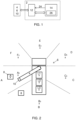
- a crane control system 2 is provided and is intended to be used for a crane 4 arranged to be mounted to a vehicle 6 for transporting a load 8.
- the crane comprises crane components such as a crane column, a crane boom system and a working tool 10 arranged at the tip of the crane for attaching the load during loading and unloading to or from the vehicle 6.
- the crane control system comprises a control unit 12 configured to generate control signals to actuators of the crane to control operation of the crane 4 and the working tool 10. This is schematically indicated by a block arrow in figure 1 .
- the control unit is also configured to receive various inputs from a plurality of sensors arranged e.g. on the vehicle, crane, and working tool.
- the crane control system also comprises a user interface unit 14 arranged to receive operator input of wanted movements of the crane for performing a working assignment with the tool.
- a working assignment may be to move a load, e.g. a waste bin or a container, from one position to another during loading/unloading.
- the user interface unit 14 is structured to established a bi-directional wireless communication link with the control unit 10. This link is implemented in accordance with any available wireless communication protocol, and is indicated by a block arrow in figure 1 .
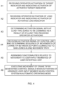
- FIG. 3 A schematic view of a part of the user interface unit 14 is shown in figure 3 .
- various items, e.g. various displays, are not shown in the figure, and only those parts necessary for describing and explaining the present invention are shown.
- the user interface unit 14 includes at least three target indicators 16 configured to receive operator activation 18 and to indicate activation.
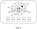
- Each target indicator represents a target zone A-F surrounding the vehicle, and has a designated three-dimensional (3D) space defined in a coordinate system in relation to the vehicle.
- Each target zone A-F of the illustrated example in figure 2 is provided with a target zone point A 0 - F 0 being a 3D point within the 3D space of the target zone.
- a target indicator 16 may receive operator activation by the operator selecting the indicator e.g. by pressing a button, pulling a lever, or pressing a part of a touch-screen associated with the target indicator.
- An activated target indicator may change appearance such as colour, e.g. from white to green, which is indicted in figure 3 by a filled black circle.
- the user interface unit 14 also includes at least two load indicators 20 configured to receive operator activation 22 and to indicate activation.
- Each load indicator represents a load zone on the vehicle, and has a designated 3D space defined in the coordinate system.
- the vehicle is schematically illustrated by a rectangle where six load indicators 20 shown on the load bed.
- Each load zone of the illustrated example in figure 2 is provided with a default load zone point L1, L2, L3 being a 3D point within the 3D space of the load zone.
- a load indicator 20 may receive operator activation by the operator selecting the indicator e.g. by pressing a button, pulling a lever, or pressing a part of a touch-screen associated with the load indicator.
- An activated load indicator may change appearance such as colour, e.g. from white to green, which is indicted in figure 3 by a filled black circle.
- the target/load indicators 16, 20 are configured to both receive operator activation and to indicate activation. They may be implemented as a single indicator, or may be implemented as separate items, i.e. one part structured to receive operator activation, and another part structured to indicate the activation.
- control unit 12 All processing of data, and storage of data, related to the target and load zones is performed by the control unit 12.
- the user interface unit 14 is configured to determine at least one activation signal 24 as a result of at least two received operator activations 18, 22 from the target/load indicator(s) 16, 20.
- the activation signal(s) 24 represents at least two zones - the operator is selecting the zones and the control unit then applies the accurate 3D points connected to those zones to be combined.
- the at least two 3D points may be represented by one activation signal, or each operator activated 3D points may be represented by separate activation signals.
- the activation signal(s) is/are applied to the control unit 12, and the control unit is configured to receive the activation signal(s) 24 including the reference to the at least two zones to be combined.
- the control unit is configured to determine that the received 3D points belong to the same working assignment. If the working assignment involves two zones received in one activation signal it is clear that they belong to the same working assignment. If the two zones are sent in separated activation signals the control unit may further determine the time interval between those signals and if the time interval is shorter than a defined time (e.g. 5-10 seconds) it will be determined that the two signals relate to the same working assignment. If more than two 3D points are involved similar determinations may be made. As an alternative the operator may actively confirm the selection of zones for a working assignment through interaction with the user interface unit.
- a defined time e.g. 5-10 seconds
- the selection of zones to be combined for the working assignment will be identified.
- this 3D point will be used by the control unit.
- the control unit is then configured to determine a sequence of movements of the crane tip between the 3D points along a movement path in either direction, and to assign functionalities related to the movement to at least one user input member 26 (e.g. levers and/or buttons) of the user interface unit 14.
- control unit When the control unit has determined the sequence of movement for the crane tip, it is configured to execute the movement of the crane tip by generating control signals, in response to activation of the at least one assigned user input member 26 when said control system 2 is in an automatic operating mode. These control signals are applied to relevant parts of the vehicle and/or the crane and is indicated by the double block arrow in figure 1 .
- a movement path may be defined as a sequence of 3D points that the working tool should follow, and may be determined in advance based upon e.g. the width and height of the vehicle, the type of crane, the size of load to be loaded/unloaded, etc.
- the 3D points connected to the selected zones will form part of the sequence of 3D points defining the movement path.
- the thus determined path may then be adjusted in dependence of input signals from various sensors arranged at the vehicle or crane until the working tool has reached the intended position.
- control unit 12 is further configured to determine a sequence of movements of the crane tip from a present position to one 3D point of a target or load zone. This may be applicable when moving the crane tip from a parked transport position on the vehicle when the vehicle is moving, e.g. when the crane is in a folded position.
- the control unit would then include the additional movement path from the present position of the crane tip to a zone selected by the operator as a preparatory movement to the defined movement path between the selected zones. This will allow the operator to control this preparatory movement in the same manner as for the movement between selected zones (and its connected 3D points).
- the defined 3D point is either a default target zone point or the default load zone point, or any present 3D point defined by a working assignment performed by the crane tip.
- the operator may actively define a present 3D point, e.g. via the user input members 26.
- the default target zone point may be applied in situations where the working tool is to be automatically moved to a target zone indicated on the target indicator for that zone.
- the working tool is automatically moved to the default target zone point, and the operator then takes over and manually controls the final movement of the working tool to the specific 3D point of the load.
- This specific position may be stored as the present target point, i.e. a present 3D point defined by a working assignment performed by the crane tip.
- the operator may update the 3D point that is connected to a zone.
- the operator may first use the default position connected to a zone where the recycling bin is located.
- the position of the working tool is adjusted from the default position to the relevant position for the attaching the working tool to the bin.
- This position of the crane tip may then be stored as a present 3D point and connected to the present zone by the operator, e.g. through a user input with the user interface device.
- the 3D point connected to the zone may be updated so that after the recycling bin has been emptied on the selected zone of the load bed the crane tip would return to the updated 3D point instead of the default position. This would improve the workflow, both in terms of time spent on the task and safety, for the operator and further support the operator with working assignment.
- the target zone point A 1 - F 1 is either a default target zone point, or any present 3D point defined by a working assignment performed by the crane tip.
- FIG 2 is illustrated a vehicle 6 from above provided with a crane 4 comprising a working tool 10 arranged at the crane tip.
- the working assignment is in this case to pick up a load 8 in target zone A.
- the working tool 10 is controlled to be moved to the default target zone point A 0 during the automatic operating mode, then the mode is changed to a manual operating mode and the operator manually controls the tool 10 to be moved to the exact position, denoted A 1 , for being connected to the load 8 to be picked up.
- a 1 indicates the present target zone point.
- control unit 12 is configured to determine the order of operator activation of target indicator(s) and/or load indicator(s) and to determine the direction of the crane tip movement between defined 3D points dependent on said order. This may be applicable in order for the operator to indicate that the crane tip should first move to a target zone including the 3D point of a waste bin to be picked up, and then move the waste bin to a specific load position on the load bed, e.g. L2, and empty the waste bin. In the described situation the operator has first activated the target indicator representing the target zone to be chosen and then activated the load indicator designating the load zone where the waste bin should be emptied. Preferably, this procedure is then continued by returning the waste bin to the place where it was picked up.
- the crane control system 2 is configured to be operated in two operating modes:
- control unit 12 is configured to determine the number, and the position, of target and/or load indicators 16, 20 on the user interface unit 14, dependent on the working assignment and/or the surroundings to the vehicle 6, and to define, on the user interface unit 14, the target and/or load indicators in dependence thereto.
- the control unit will then generate definition signals and applying those signals to the user interface unit that adapts target and/or load indicators 16, 20 accordingly.
- six target zones are indicated by six target indicators on the user interface unit.
- the working assignment indicates that bins to be load will be on the right side of the vehicle, only three target indicators need to be displayed.
- six load zones on the schematic image of the vehicle are indicated by six load indicators on the user interface unit. In a situation where only three load zones are available, e.g. as shown in figure 2 , only three load indicators will be shown.
- a vehicle 6 that comprises a crane control system 2 which has been described above.
- the vehicle may be of any type provided with a crane, and one implementation are vehicle mounted loader cranes, but the system and method may naturally also be implemented on other types of cranes such as mobile cranes.
- the present invention also relates to a method of a crane control system 2 for a crane 4 arranged to be mounted to a vehicle 6 for transporting a load 8.
- the crane comprises crane components such as a crane column, a crane boom system and a working tool 10 arranged at the tip of the crane for attaching the load during loading and unloading to or from the vehicle 6.
- the crane control system comprises a control unit 12 configured to generate control signals to actuators of the crane to control operation of the crane 4 and the working tool 10, and a user interface unit 14 arranged to receive operator input of wanted movements of the crane for performing a working assignment with the tool.
- the method is schematically illustrated by the flow diagram shown in figure 4 , and comprises method steps A1-A6:
- the method comprises determining a sequence of movements of the crane tip from a present position to one 3D point of a target or load zone.
- the defined 3D point is either a default target zone point or said default load zone point, or any present 3D point defined by a working assignment performed by the crane tip.
- the method comprises determining the order of operator activation of target indicators(s) and/or load indicator(s) and determining the direction of the crane tip movement between defined 3D points dependent on said order.
- the method preferably comprises operating the crane control system 2 in two operating modes:
- the method comprises determining the number, and the position, of target and/or load indicators 16, 20 on the user interface unit 14, dependent on the working assignment and/or the surroundings to the vehicle 6, and defining, on the user interface unit 14, the target and/or load indicators in dependence thereto.
- the automatic procedure described in relation to the system and method is dynamic, which means that start and end positions may be varied in dependence of the real procedure. For example, if during manual control in a target zone a specific position of a target (e.g. the position where a crane tip connects to a container) is determined and that position is then applied in a next step, e.g. when returning e.g. the container to the position where it was picked up.
- a target e.g. the position where a crane tip connects to a container
- a movement path may for example be calculated for the tip of the crane and the movements of the respective boom cylinders are then deduced based on this.
- the automatic movements of the crane booms as well as the movement path may be adapted during operation.
- An alternative would be to have pre-stored paths for different load and target positions.
- a created movement scheme is assigned to a user input member, such as a button or a lever, on the remote user interface unit, and the execution instructions, such as initiation of movement scheme, speed of the tip of the crane during the movement scheme or halting the movement scheme, are further generated based of the operator's interaction with the user input members of the user interface unit.
Landscapes
- Engineering & Computer Science (AREA)
- Automation & Control Theory (AREA)
- Mechanical Engineering (AREA)
- Human Computer Interaction (AREA)
- Manufacturing & Machinery (AREA)
- Physics & Mathematics (AREA)
- General Physics & Mathematics (AREA)
- Jib Cranes (AREA)
Claims (14)
- Kransteuersystem (2) für einen Kran (4), der angeordnet ist, um an einem Fahrzeug (6) zum Transportieren einer Last (8) montiert zu werden, wobei der Kran Krankomponenten umfasst, wie etwa einen Kranmast, ein Kranauslegersystem und ein Arbeitswerkzeug (10), das an der Spitze des Krans zum Anbringen einer Last während des Beladens auf das Fahrzeug (6) und Entladens von diesem angeordnet ist, wobei das Kransteuersystem Folgendes umfasst- eine Steuereinheit (12), die dazu konfiguriert ist, Steuersignale für Aktoren des Krans zu erzeugen, um den Betrieb des Krans (4) und des Arbeitswerkzeugs (10) zu steuern,- eine Benutzerschnittstelleneinheit (14), die angeordnet ist, um Bedienereingaben von gewünschten Bewegungen des Krans zum Durchführen einer Tätigkeit mit dem Werkzeug zu empfangen, wobei die Benutzerschnittstelleneinheit (14) Folgendes beinhaltet:- mindestens drei Zielindikatoren (16), die dazu konfiguriert sind, eine Bedieneraktivierung (18) zu empfangen und eine Aktivierung anzuzeigen, wobei jeder Zielindikator eine Zielzone A-F darstellt, die das Fahrzeug umgibt, und einen bestimmten dreidimensionalen (3D) Raum aufweist, der in einem Koordinatensystem in Bezug auf das Fahrzeug definiert ist, und wobei ein Zielzonenpunkt A0-F0 ein 3D-Punkt innerhalb des 3D-Raums ist, und- mindestens zwei Lastindikatoren (20), die dazu konfiguriert sind, eine Bedieneraktivierung (22) zu empfangen und eine Aktivierung anzuzeigen, wobei jeder Lastindikator eine Lastzone an dem Fahrzeug darstellt und einen bestimmten 3D-Raum aufweist, der durch das Koordinatensystem definiert ist, und wobei ein Lastzonenpunkt L1, L2, L3 ein 3D-Punkt innerhalb des 3D-Raums ist,wobei in Abhängigkeit von der Tätigkeit eine Teilgruppe der Ziel- und Lastzonen so eingestellt werden kann, dass sie für den Bediener verfügbar und durch ihn auswählbar ist, wobei die Benutzerschnittstelleneinheit (14) dazu konfiguriert ist, mindestens ein Aktivierungssignal (24) als ein Ergebnis von mindestens zwei empfangenen Bedieneraktivierungen (18, 22) von dem/den Ziel-/Lastindikator(en) (16, 20) zu bestimmen, wobei das/die Aktivierungssignal(e) (24) mindestens zwei unterschiedliche Zonen darstellt/darstellen, und das/die Aktivierungssignal(e) auf die Steuereinheit (12) anzuwenden, und wobei die Steuereinheit zu Folgendem konfiguriert ist:- Empfangen des Aktivierungssignals/der Aktivierungssignale (24);- Bestimmen einer Sequenz von Bewegungen der Kranspitze zwischen 3D-Punkten, die mit den Zonen entlang eines Bewegungsweges in beide Richtungen verbunden sind,- Zuweisen von Funktionalitäten in Bezug auf die Bewegung zu mindestens einem Benutzereingabeelement (26) der Benutzerschnittstelleneinheit (14) und- Ausführen der Bewegung der Kranspitze durch Erzeugen von Steuersignalen als Reaktion auf eine Aktivierung des mindestens einen zugewiesenen Benutzereingabeelements (26), wenn sich das Steuersystem (2) in einem automatischen Betriebsmodus befindet,wobei das Kransteuersystem (2) dazu konfiguriert ist, in einem manuellen Betriebsmodus betrieben zu werden, wobei der Kran (4) durch Steuersignale betrieben wird, die als Reaktion auf eine Bedienereingabe von Kranbewegungen über die Benutzereingabeelemente (26) erzeugt werden, und wobei beim Erreichen des 3D-Punkts am Ende der ausgeführten Bewegung das Steuersystem dazu konfiguriert ist, in dem manuellen Betriebsmodus betrieben zu werden, der es dem Bediener ermöglicht, den letzten Teil der Bewegung von der Endposition zu der genauen Position von z. B. dem Beladen oder Entladen zu übernehmen.
- Kransteuersystem (2) nach Anspruch 1, wobei die Steuereinheit (12) ferner dazu konfiguriert ist, eine Sequenz von Bewegungen der Kranspitze von einer gegenwärtigen Position zu einem 3D-Punkt einer Ziel- oder Lastzone zu bestimmen.
- Kransteuersystem (2) nach Anspruch 1 oder 2, wobei der definierte 3D-Punkt entweder ein Standardzielzonenpunkt oder ein Standardlastzonenpunkt oder ein beliebiger 3D-Punkt ist, der während einer Tätigkeit definiert ist, die durch die Kranspitze durchgeführt wird.
- Kransteuersystem (2) nach einem der Ansprüche 1-3, wobei die Steuereinheit (12) dazu konfiguriert ist, die Reihenfolge der Bedieneraktivierung von (einem) Zielindikator(en) und/oder (einem) Lastindikator(en) zu bestimmen und die Richtung der Bewegung der Kranspitze zwischen definierten 3D-Punkten in Abhängigkeit von der Reihenfolge zu bestimmen.
- Kransteuersystem (2) nach einem der Ansprüche 1-4, wobei das Kransteuersystem (2) in zwei Betriebsmodi betrieben wird:dem manuellen Betriebsmodus, wobei der Kran (4) durch Steuersignale betrieben wird, die als Reaktion auf eine Bedienereingabe von Kranbewegungen über die Benutzereingabeelemente (26) erzeugt werden, unddem automatischen Betriebsmodus, der durch den Bediener aktiviert wird, und wobei die Krangeometrie und die Kranspitzenposition gemäß einer Sequenz von Bewegungen geändert werden, die durch die Steuereinheit (12) bestimmt wird.
- Kransteuersystem (2) nach Anspruch 5, wobei die Steuereinheit (12) dazu konfiguriert ist, den Betriebsmodus zwischen dem manuellen und dem automatischen Betriebsmodus während der Sequenz von Bewegungen zu ändern.
- Kransteuersystem (2) nach einem der Ansprüche 1-6, wobei die Steuereinheit (12) dazu konfiguriert ist, die Anzahl und die Position von Ziel- und/oder Lastindikatoren (16, 20) an der Benutzerschnittstelleneinheit (14) in Abhängigkeit von der Tätigkeit und/oder der Umgebung des Fahrzeugs (6) zu bestimmen und an der Benutzerschnittstelleneinheit (14) die Ziel- und/oder Lastindikatoren in Abhängigkeit davon zu definieren.
- Fahrzeug (6), umfassend einen Kran und ein Kransteuersystem (2) nach einem der Ansprüche 1-7.
- Verfahren eines Kransteuersystems (2) für einen Kran (4), der angeordnet ist, um an einem Fahrzeug (6) zum Transportieren einer Last (8) montiert zu werden, wobei der Kran Krankomponenten umfasst, wie etwa einen Kranmast, ein Kranauslegersystem und ein Arbeitswerkzeug (10), das an der Spitze des Krans zum Anbringen einer Last während des Beladens auf das Fahrzeug (6) und Entladens von diesem angeordnet ist, wobei das Kransteuersystem Folgendes umfasst- eine Steuereinheit (12), die dazu konfiguriert ist, Steuersignale für Aktoren des Krans zu erzeugen, um den Betrieb des Krans (4) und des Arbeitswerkzeugs (10) zu steuern,- eine Benutzerschnittstelleneinheit (14), die angeordnet ist, um Bedienereingaben von gewünschten Bewegungen des Krans zum Durchführen einer Tätigkeit mit dem Werkzeug zu empfangen, wobei dieses Verfahren Folgendes umfasst:wobei das Kransteuersystem (2) dazu konfiguriert ist, in einem manuellen Betriebsmodus betrieben zu werden, wobei der Kran (4) durch Steuersignale betrieben wird, die als Reaktion auf eine Bedienereingabe von Kranbewegungen über die Benutzereingabeelemente (26) erzeugt werden, und wobei das Verfahren beim Erreichen des 3D-Punkts am Ende der ausgeführten Bewegung ferner Folgendes umfasst:A1 - Empfangen einer Bedieneraktivierung (18) des Zielindikators (16) und Anzeigen einer Aktivierung des aktivierten Zielindikators, wobei jeder Zielindikator eine Zielzone A-F darstellt, die das Fahrzeug umgibt, und einen bestimmten dreidimensionalen (3D) Raum aufweist, der in einem Koordinatensystem in Bezug auf das Fahrzeug definiert ist, und wobei ein Zielzonenpunkt A0-F0 ein 3D-Punkt innerhalb des 3D-Raums ist,A2 - Empfangen einer Bedieneraktivierung (22) des Lastindikators (20) und Anzeigen einer Aktivierung des aktivierten Lastindikators, wobei jeder Lastindikator eine Lastzone an dem Fahrzeug darstellt und einen bestimmten 3D-Raum aufweist, der in dem Koordinatensystem definiert ist, und wobei ein Lastzonenpunkt L1, L2, L3 ein 3D-Punkt innerhalb des 3D-Raums ist, wobei abhängig von der Tätigkeit eine Untergruppe der Ziel- und Lastzonen so eingestellt werden kann, dass sie für den Bediener verfügbar und durch diesen auswählbar ist,A3 - Bestimmen von mindestens einem Aktivierungssignal (24) als Ergebnis von mindestens zwei empfangenen Bedieneraktivierungen (18, 22) von dem/den Ziel-/Lastindikator(en) (16, 20), wobei das/die Aktivierungssignal(e) (24) mindestens zwei unterschiedliche Zonen darstellt/darstellen, und Anwenden des Aktivierungssignals/der Aktivierungssignale auf die Steuereinheit (12),A4 - Empfangen, durch die Steuereinheit, des Aktivierungssignals/der Aktivierungssignale (24);- Bestimmen einer Sequenz von Bewegungen der Kranspitze zwischen den 3D-Punkten, die mit den Zonen entlang eines Bewegungsweges in beide Richtungen verbunden sind,A5 - Zuweisen von Funktionalitäten in Bezug auf die Bewegung zu mindestens einem Benutzereingabeelement (26) der Benutzerschnittstelleneinheit (14) undA6 - Ausführen der Bewegung der Kranspitze durch Erzeugen von Steuersignalen als Reaktion auf eine Aktivierung des mindestens einen zugewiesenen Benutzereingabeelements (26), wenn sich das Steuersystem (2) in einem automatischen Betriebsmodus befindet,- Betreiben des Steuersystems in dem manuellen Betriebsmodus, der es dem Bediener ermöglicht, den letzten Teil der Bewegung von der Endposition zu der genauen Position von z. B. dem Laden oder Entladen zu übernehmen.
- Verfahren nach Anspruch 9, umfassend Bestimmen einer Sequenz von Bewegungen der Kranspitze von einer gegenwärtigen Position zu einem 3D-Punkt einer Ziel- oder Lastzone.
- Verfahren nach Anspruch 9 oder 10, wobei der definierte 3D-Punkt entweder ein Standardzielzonenpunkt oder ein Standardlastzonenpunkt oder ein beliebiger 3D-Punkt ist, der durch eine Tätigkeit definiert ist, die durch die Kranspitze durchgeführt wird.
- Verfahren nach einem der Ansprüche 9-11, umfassend Bestimmen der Reihenfolge der Bedieneraktivierung von (einem) Zielindikator(en) und/oder (einem) Lastindikatoren) und Bestimmen der Richtung der Bewegung der Kranspitze zwischen definierten 3D-Punkten in Abhängigkeit von der Reihenfolge.
- Verfahren nach einem der Ansprüche 9-11, umfassend Betreiben des Kransteuersystems (2) in zwei Betriebsmodi:dem manuellen Betriebsmodus, wobei der Kran (4) durch Steuersignale betrieben wird, die als Reaktion auf eine Bedienereingabe über die Benutzereingabeelemente (26) erzeugt werden, unddem automatischen Betriebsmodus, der durch den Bediener aktiviert wird, und wobei die Krangeometrie und die Kranspitzenposition gemäß einer Sequenz von Bewegungen geändert werden, die durch die Steuereinheit (12) bestimmt wird, und wobei das Verfahren Ändern des Betriebsmodus zwischen dem manuellen und dem automatischen Betriebsmodus während der Sequenz von Bewegungen umfasst.
- Verfahren nach einem der Ansprüche 9-13, umfassend Bestimmen der Anzahl und der Position von Ziel- und/oder Lastindikatoren (16, 20) an der Benutzerschnittstelleneinheit (14), abhängig von der Tätigkeit und/oder der Umgebung des Fahrzeugs (6), und Definieren, an der Benutzerschnittstelleneinheit (14), der Ziel- und/oder Lastindikatoren in Abhängigkeit davon.
Priority Applications (1)
| Application Number | Priority Date | Filing Date | Title |
|---|---|---|---|
| EP19218394.5A EP3839675B8 (de) | 2019-12-20 | 2019-12-20 | Kransteuerungssystem, fahrzeug und verfahren in zusammenhang mit dem system |
Applications Claiming Priority (1)
| Application Number | Priority Date | Filing Date | Title |
|---|---|---|---|
| EP19218394.5A EP3839675B8 (de) | 2019-12-20 | 2019-12-20 | Kransteuerungssystem, fahrzeug und verfahren in zusammenhang mit dem system |
Publications (4)
| Publication Number | Publication Date |
|---|---|
| EP3839675A1 EP3839675A1 (de) | 2021-06-23 |
| EP3839675C0 EP3839675C0 (de) | 2024-07-24 |
| EP3839675B1 true EP3839675B1 (de) | 2024-07-24 |
| EP3839675B8 EP3839675B8 (de) | 2024-09-04 |
Family
ID=69411045
Family Applications (1)
| Application Number | Title | Priority Date | Filing Date |
|---|---|---|---|
| EP19218394.5A Active EP3839675B8 (de) | 2019-12-20 | 2019-12-20 | Kransteuerungssystem, fahrzeug und verfahren in zusammenhang mit dem system |
Country Status (1)
| Country | Link |
|---|---|
| EP (1) | EP3839675B8 (de) |
Families Citing this family (1)
| Publication number | Priority date | Publication date | Assignee | Title |
|---|---|---|---|---|
| AT17996U1 (de) * | 2022-05-13 | 2023-10-15 | Palfinger Ag | Verfahren zum Bewegen einer Hebevorrichtung |
Citations (2)
| Publication number | Priority date | Publication date | Assignee | Title |
|---|---|---|---|---|
| EP3553460A1 (de) * | 2016-12-09 | 2019-10-16 | Tadano Ltd. | Kran |
| WO2019229751A1 (en) * | 2018-05-30 | 2019-12-05 | Syracuse Ltd. | System and method for transporting a swaying hoisted load |
Family Cites Families (3)
| Publication number | Priority date | Publication date | Assignee | Title |
|---|---|---|---|---|
| US8909467B2 (en) * | 2010-06-07 | 2014-12-09 | Industry-Academic Cooperation Foundation, Yonsei University | Tower crane navigation system |
| AT14237U1 (de) * | 2014-01-31 | 2015-06-15 | Palfinger Ag | Kransteuerung |
| DK179958B1 (en) * | 2018-04-13 | 2019-11-04 | Hmf Group A/S | Crane and Method for Operating a Crane |
-
2019
- 2019-12-20 EP EP19218394.5A patent/EP3839675B8/de active Active
Patent Citations (2)
| Publication number | Priority date | Publication date | Assignee | Title |
|---|---|---|---|---|
| EP3553460A1 (de) * | 2016-12-09 | 2019-10-16 | Tadano Ltd. | Kran |
| WO2019229751A1 (en) * | 2018-05-30 | 2019-12-05 | Syracuse Ltd. | System and method for transporting a swaying hoisted load |
Also Published As
| Publication number | Publication date |
|---|---|
| EP3839675C0 (de) | 2024-07-24 |
| EP3839675B8 (de) | 2024-09-04 |
| EP3839675A1 (de) | 2021-06-23 |
Similar Documents
| Publication | Publication Date | Title |
|---|---|---|
| US11599092B2 (en) | Construction machine, in particular a crane, and method for the control thereof | |
| US20210223753A1 (en) | Method and Device for Planning and/or Controlling and/or Simulating the Operation of a Construction Machine | |
| US9574892B2 (en) | System, method, and app for managing waste services | |
| CN103339056B (zh) | 用起重机来定位载荷并获取定位的载荷或堆积载荷的方法 | |
| CN109895105A (zh) | 一种智能装置 | |
| US20220119233A1 (en) | Method and device for controlling a materials handling and/or construction machine | |
| EP3839675B1 (de) | Kransteuerungssystem, fahrzeug und verfahren in zusammenhang mit dem system | |
| CN114859768A (zh) | 用于包括工具的工程机械的远程操作的系统和方法 | |
| US20190322498A1 (en) | Safety system | |
| EP3554983B1 (de) | Arbeitsfahrzeug mit einem kran | |
| IT201800010234A1 (it) | Telehandler con sistema di controllo. | |
| US20240184540A1 (en) | System for process flow templating and duplication of tasks within material flow automation | |
| KR101837906B1 (ko) | 스태커 및 리클라이머 장비의 자동 운전을 통한 야드 관리 시스템 | |
| RU2399576C1 (ru) | Устройство управления строительной машиной (варианты) | |
| EP4056418A1 (de) | Hakenliftanordnung und verfahren einer hakenliftanordnung | |
| CN120092118A (zh) | 具有智能控制系统的搭载工具的拆除机器人以及控制作为拆除机器人一部分的机器子系统的方法 | |
| EP4650316A1 (de) | Krananordnung und verfahren zur steuerung davon | |
| US20240184293A1 (en) | Just-in-time destination and route planning | |
| JP2020142880A (ja) | クレーンの運転支援システム及び運転支援方法 | |
| US11718509B2 (en) | Vehicle comprising a working equipment, and a working equipment, and a method in relation thereto | |
| US11198598B2 (en) | Vehicle provided with a control system, and a method related to the vehicle | |
| WO2025204233A1 (ja) | 施工システム | |
| CN119647864A (zh) | 物料搬运车辆的调度方法、装置、存储介质和车辆 | |
| KR20220025474A (ko) | 중장비 보유 수량의 적정성 진단 시스템 및 방법 | |
| WO2018103928A1 (en) | A vehicle, and a method for a vehicle, including target marker on an overview image |
Legal Events
| Date | Code | Title | Description |
|---|---|---|---|
| PUAI | Public reference made under article 153(3) epc to a published international application that has entered the european phase |
Free format text: ORIGINAL CODE: 0009012 |
|
| STAA | Information on the status of an ep patent application or granted ep patent |
Free format text: STATUS: THE APPLICATION HAS BEEN PUBLISHED |
|
| AK | Designated contracting states |
Kind code of ref document: A1 Designated state(s): AL AT BE BG CH CY CZ DE DK EE ES FI FR GB GR HR HU IE IS IT LI LT LU LV MC MK MT NL NO PL PT RO RS SE SI SK SM TR |
|
| STAA | Information on the status of an ep patent application or granted ep patent |
Free format text: STATUS: REQUEST FOR EXAMINATION WAS MADE |
|
| 17P | Request for examination filed |
Effective date: 20211214 |
|
| RBV | Designated contracting states (corrected) |
Designated state(s): AL AT BE BG CH CY CZ DE DK EE ES FI FR GB GR HR HU IE IS IT LI LT LU LV MC MK MT NL NO PL PT RO RS SE SI SK SM TR |
|
| STAA | Information on the status of an ep patent application or granted ep patent |
Free format text: STATUS: EXAMINATION IS IN PROGRESS |
|
| 17Q | First examination report despatched |
Effective date: 20221021 |
|
| GRAP | Despatch of communication of intention to grant a patent |
Free format text: ORIGINAL CODE: EPIDOSNIGR1 |
|
| STAA | Information on the status of an ep patent application or granted ep patent |
Free format text: STATUS: GRANT OF PATENT IS INTENDED |
|
| INTG | Intention to grant announced |
Effective date: 20240326 |
|
| GRAS | Grant fee paid |
Free format text: ORIGINAL CODE: EPIDOSNIGR3 |
|
| GRAA | (expected) grant |
Free format text: ORIGINAL CODE: 0009210 |
|
| STAA | Information on the status of an ep patent application or granted ep patent |
Free format text: STATUS: THE PATENT HAS BEEN GRANTED |
|
| REG | Reference to a national code |
Ref country code: DE Ref legal event code: R081 Ref document number: 602019055628 Country of ref document: DE Owner name: HIAB AB, SE Free format text: FORMER OWNER: HIAB AB, KISTA, SE |
|
| AK | Designated contracting states |
Kind code of ref document: B1 Designated state(s): AL AT BE BG CH CY CZ DE DK EE ES FI FR GB GR HR HU IE IS IT LI LT LU LV MC MK MT NL NO PL PT RO RS SE SI SK SM TR |
|
| REG | Reference to a national code |
Ref country code: GB Ref legal event code: FG4D |
|
| REG | Reference to a national code |
Ref country code: CH Ref legal event code: EP |
|
| RAP4 | Party data changed (patent owner data changed or rights of a patent transferred) |
Owner name: HIAB AB |
|
| REG | Reference to a national code |
Ref country code: IE Ref legal event code: FG4D Ref country code: DE Ref legal event code: R096 Ref document number: 602019055628 Country of ref document: DE |
|
| REG | Reference to a national code |
Ref country code: CH Ref legal event code: PK Free format text: BERICHTIGUNG B8 |
|
| U01 | Request for unitary effect filed |
Effective date: 20240809 |
|
| U07 | Unitary effect registered |
Designated state(s): AT BE BG DE DK EE FI FR IT LT LU LV MT NL PT SE SI Effective date: 20240826 |
|
| PG25 | Lapsed in a contracting state [announced via postgrant information from national office to epo] |
Ref country code: NO Free format text: LAPSE BECAUSE OF FAILURE TO SUBMIT A TRANSLATION OF THE DESCRIPTION OR TO PAY THE FEE WITHIN THE PRESCRIBED TIME-LIMIT Effective date: 20241024 |
|
| PG25 | Lapsed in a contracting state [announced via postgrant information from national office to epo] |
Ref country code: GR Free format text: LAPSE BECAUSE OF FAILURE TO SUBMIT A TRANSLATION OF THE DESCRIPTION OR TO PAY THE FEE WITHIN THE PRESCRIBED TIME-LIMIT Effective date: 20241025 Ref country code: PL Free format text: LAPSE BECAUSE OF FAILURE TO SUBMIT A TRANSLATION OF THE DESCRIPTION OR TO PAY THE FEE WITHIN THE PRESCRIBED TIME-LIMIT Effective date: 20240724 |
|
| PG25 | Lapsed in a contracting state [announced via postgrant information from national office to epo] |
Ref country code: IS Free format text: LAPSE BECAUSE OF FAILURE TO SUBMIT A TRANSLATION OF THE DESCRIPTION OR TO PAY THE FEE WITHIN THE PRESCRIBED TIME-LIMIT Effective date: 20241124 |
|
| PG25 | Lapsed in a contracting state [announced via postgrant information from national office to epo] |
Ref country code: HR Free format text: LAPSE BECAUSE OF FAILURE TO SUBMIT A TRANSLATION OF THE DESCRIPTION OR TO PAY THE FEE WITHIN THE PRESCRIBED TIME-LIMIT Effective date: 20240724 |
|
| PG25 | Lapsed in a contracting state [announced via postgrant information from national office to epo] |
Ref country code: RS Free format text: LAPSE BECAUSE OF FAILURE TO SUBMIT A TRANSLATION OF THE DESCRIPTION OR TO PAY THE FEE WITHIN THE PRESCRIBED TIME-LIMIT Effective date: 20241024 Ref country code: ES Free format text: LAPSE BECAUSE OF FAILURE TO SUBMIT A TRANSLATION OF THE DESCRIPTION OR TO PAY THE FEE WITHIN THE PRESCRIBED TIME-LIMIT Effective date: 20240724 |
|
| U20 | Renewal fee for the european patent with unitary effect paid |
Year of fee payment: 6 Effective date: 20241225 |
|
| PG25 | Lapsed in a contracting state [announced via postgrant information from national office to epo] |
Ref country code: RS Free format text: LAPSE BECAUSE OF FAILURE TO SUBMIT A TRANSLATION OF THE DESCRIPTION OR TO PAY THE FEE WITHIN THE PRESCRIBED TIME-LIMIT Effective date: 20241024 Ref country code: PL Free format text: LAPSE BECAUSE OF FAILURE TO SUBMIT A TRANSLATION OF THE DESCRIPTION OR TO PAY THE FEE WITHIN THE PRESCRIBED TIME-LIMIT Effective date: 20240724 Ref country code: NO Free format text: LAPSE BECAUSE OF FAILURE TO SUBMIT A TRANSLATION OF THE DESCRIPTION OR TO PAY THE FEE WITHIN THE PRESCRIBED TIME-LIMIT Effective date: 20241024 Ref country code: IS Free format text: LAPSE BECAUSE OF FAILURE TO SUBMIT A TRANSLATION OF THE DESCRIPTION OR TO PAY THE FEE WITHIN THE PRESCRIBED TIME-LIMIT Effective date: 20241124 Ref country code: HR Free format text: LAPSE BECAUSE OF FAILURE TO SUBMIT A TRANSLATION OF THE DESCRIPTION OR TO PAY THE FEE WITHIN THE PRESCRIBED TIME-LIMIT Effective date: 20240724 Ref country code: GR Free format text: LAPSE BECAUSE OF FAILURE TO SUBMIT A TRANSLATION OF THE DESCRIPTION OR TO PAY THE FEE WITHIN THE PRESCRIBED TIME-LIMIT Effective date: 20241025 Ref country code: ES Free format text: LAPSE BECAUSE OF FAILURE TO SUBMIT A TRANSLATION OF THE DESCRIPTION OR TO PAY THE FEE WITHIN THE PRESCRIBED TIME-LIMIT Effective date: 20240724 |
|
| PG25 | Lapsed in a contracting state [announced via postgrant information from national office to epo] |
Ref country code: SM Free format text: LAPSE BECAUSE OF FAILURE TO SUBMIT A TRANSLATION OF THE DESCRIPTION OR TO PAY THE FEE WITHIN THE PRESCRIBED TIME-LIMIT Effective date: 20240724 Ref country code: RO Free format text: LAPSE BECAUSE OF FAILURE TO SUBMIT A TRANSLATION OF THE DESCRIPTION OR TO PAY THE FEE WITHIN THE PRESCRIBED TIME-LIMIT Effective date: 20240724 |
|
| PG25 | Lapsed in a contracting state [announced via postgrant information from national office to epo] |
Ref country code: CZ Free format text: LAPSE BECAUSE OF FAILURE TO SUBMIT A TRANSLATION OF THE DESCRIPTION OR TO PAY THE FEE WITHIN THE PRESCRIBED TIME-LIMIT Effective date: 20240724 |
|
| PG25 | Lapsed in a contracting state [announced via postgrant information from national office to epo] |
Ref country code: SK Free format text: LAPSE BECAUSE OF FAILURE TO SUBMIT A TRANSLATION OF THE DESCRIPTION OR TO PAY THE FEE WITHIN THE PRESCRIBED TIME-LIMIT Effective date: 20240724 |
|
| PLBE | No opposition filed within time limit |
Free format text: ORIGINAL CODE: 0009261 |
|
| STAA | Information on the status of an ep patent application or granted ep patent |
Free format text: STATUS: NO OPPOSITION FILED WITHIN TIME LIMIT |
|
| 26N | No opposition filed |
Effective date: 20250425 |
|
| PG25 | Lapsed in a contracting state [announced via postgrant information from national office to epo] |
Ref country code: MC Free format text: LAPSE BECAUSE OF FAILURE TO SUBMIT A TRANSLATION OF THE DESCRIPTION OR TO PAY THE FEE WITHIN THE PRESCRIBED TIME-LIMIT Effective date: 20240724 |
|
| REG | Reference to a national code |
Ref country code: CH Ref legal event code: PL |
|
| GBPC | Gb: european patent ceased through non-payment of renewal fee |
Effective date: 20241220 |
|
| PG25 | Lapsed in a contracting state [announced via postgrant information from national office to epo] |
Ref country code: GB Free format text: LAPSE BECAUSE OF NON-PAYMENT OF DUE FEES Effective date: 20241220 |
|
| PG25 | Lapsed in a contracting state [announced via postgrant information from national office to epo] |
Ref country code: CH Free format text: LAPSE BECAUSE OF NON-PAYMENT OF DUE FEES Effective date: 20241231 |
|
| PG25 | Lapsed in a contracting state [announced via postgrant information from national office to epo] |
Ref country code: IE Free format text: LAPSE BECAUSE OF NON-PAYMENT OF DUE FEES Effective date: 20241220 |