EP3554983B1 - Arbeitsfahrzeug mit einem kran - Google Patents
Arbeitsfahrzeug mit einem kran Download PDFInfo
- Publication number
- EP3554983B1 EP3554983B1 EP17787670.3A EP17787670A EP3554983B1 EP 3554983 B1 EP3554983 B1 EP 3554983B1 EP 17787670 A EP17787670 A EP 17787670A EP 3554983 B1 EP3554983 B1 EP 3554983B1
- Authority
- EP
- European Patent Office
- Prior art keywords
- crane
- tip tool
- mode
- working vehicle
- tool
- Prior art date
- Legal status (The legal status is an assumption and is not a legal conclusion. Google has not performed a legal analysis and makes no representation as to the accuracy of the status listed.)
- Active
Links
Images

Classifications
-
- B—PERFORMING OPERATIONS; TRANSPORTING
- B66—HOISTING; LIFTING; HAULING
- B66C—CRANES; LOAD-ENGAGING ELEMENTS OR DEVICES FOR CRANES, CAPSTANS, WINCHES, OR TACKLES
- B66C23/00—Cranes comprising essentially a beam, boom, or triangular structure acting as a cantilever and mounted for translatory of swinging movements in vertical or horizontal planes or a combination of such movements, e.g. jib-cranes, derricks, tower cranes
- B66C23/06—Cranes comprising essentially a beam, boom, or triangular structure acting as a cantilever and mounted for translatory of swinging movements in vertical or horizontal planes or a combination of such movements, e.g. jib-cranes, derricks, tower cranes with jibs mounted for jibbing or luffing movements
- B66C23/08—Cranes comprising essentially a beam, boom, or triangular structure acting as a cantilever and mounted for translatory of swinging movements in vertical or horizontal planes or a combination of such movements, e.g. jib-cranes, derricks, tower cranes with jibs mounted for jibbing or luffing movements and adapted to move the loads in predetermined paths
-
- B—PERFORMING OPERATIONS; TRANSPORTING
- B66—HOISTING; LIFTING; HAULING
- B66F—HOISTING, LIFTING, HAULING OR PUSHING, NOT OTHERWISE PROVIDED FOR, e.g. DEVICES WHICH APPLY A LIFTING OR PUSHING FORCE DIRECTLY TO THE SURFACE OF A LOAD
- B66F9/00—Devices for lifting or lowering bulky or heavy goods for loading or unloading purposes
- B66F9/06—Devices for lifting or lowering bulky or heavy goods for loading or unloading purposes movable, with their loads, on wheels or the like, e.g. fork-lift trucks
- B66F9/065—Devices for lifting or lowering bulky or heavy goods for loading or unloading purposes movable, with their loads, on wheels or the like, e.g. fork-lift trucks non-masted
- B66F9/0655—Devices for lifting or lowering bulky or heavy goods for loading or unloading purposes movable, with their loads, on wheels or the like, e.g. fork-lift trucks non-masted with a telescopic boom
-
- B—PERFORMING OPERATIONS; TRANSPORTING
- B25—HAND TOOLS; PORTABLE POWER-DRIVEN TOOLS; MANIPULATORS
- B25J—MANIPULATORS; CHAMBERS PROVIDED WITH MANIPULATION DEVICES
- B25J9/00—Program-controlled manipulators
- B25J9/16—Program controls
- B25J9/1679—Program controls characterised by the tasks executed
- B25J9/1687—Assembly, peg and hole, palletising, straight line, weaving pattern movement
-
- B—PERFORMING OPERATIONS; TRANSPORTING
- B66—HOISTING; LIFTING; HAULING
- B66C—CRANES; LOAD-ENGAGING ELEMENTS OR DEVICES FOR CRANES, CAPSTANS, WINCHES, OR TACKLES
- B66C1/00—Load-engaging elements or devices attached to lifting or lowering gear of cranes or adapted for connection therewith for transmitting lifting forces to articles or groups of articles
- B66C1/10—Load-engaging elements or devices attached to lifting or lowering gear of cranes or adapted for connection therewith for transmitting lifting forces to articles or groups of articles by mechanical means
- B66C1/42—Gripping members engaging only the external or internal surfaces of the articles
- B66C1/58—Gripping members engaging only the external or internal surfaces of the articles and deforming the articles, e.g. by using gripping members such as tongs or grapples
- B66C1/585—Log grapples
-
- B—PERFORMING OPERATIONS; TRANSPORTING
- B66—HOISTING; LIFTING; HAULING
- B66C—CRANES; LOAD-ENGAGING ELEMENTS OR DEVICES FOR CRANES, CAPSTANS, WINCHES, OR TACKLES
- B66C1/00—Load-engaging elements or devices attached to lifting or lowering gear of cranes or adapted for connection therewith for transmitting lifting forces to articles or groups of articles
- B66C1/68—Load-engaging elements or devices attached to lifting or lowering gear of cranes or adapted for connection therewith for transmitting lifting forces to articles or groups of articles mounted on, or guided by, jibs
-
- B—PERFORMING OPERATIONS; TRANSPORTING
- B66—HOISTING; LIFTING; HAULING
- B66C—CRANES; LOAD-ENGAGING ELEMENTS OR DEVICES FOR CRANES, CAPSTANS, WINCHES, OR TACKLES
- B66C13/00—Other constructional features or details
- B66C13/18—Control systems or devices
- B66C13/46—Position indicators for suspended loads or for crane elements
-
- B—PERFORMING OPERATIONS; TRANSPORTING
- B66—HOISTING; LIFTING; HAULING
- B66F—HOISTING, LIFTING, HAULING OR PUSHING, NOT OTHERWISE PROVIDED FOR, e.g. DEVICES WHICH APPLY A LIFTING OR PUSHING FORCE DIRECTLY TO THE SURFACE OF A LOAD
- B66F9/00—Devices for lifting or lowering bulky or heavy goods for loading or unloading purposes
- B66F9/06—Devices for lifting or lowering bulky or heavy goods for loading or unloading purposes movable, with their loads, on wheels or the like, e.g. fork-lift trucks
- B66F9/061—Devices for lifting or lowering bulky or heavy goods for loading or unloading purposes movable, with their loads, on wheels or the like, e.g. fork-lift trucks characterised by having a lifting jib
-
- B—PERFORMING OPERATIONS; TRANSPORTING
- B66—HOISTING; LIFTING; HAULING
- B66F—HOISTING, LIFTING, HAULING OR PUSHING, NOT OTHERWISE PROVIDED FOR, e.g. DEVICES WHICH APPLY A LIFTING OR PUSHING FORCE DIRECTLY TO THE SURFACE OF A LOAD
- B66F9/00—Devices for lifting or lowering bulky or heavy goods for loading or unloading purposes
- B66F9/06—Devices for lifting or lowering bulky or heavy goods for loading or unloading purposes movable, with their loads, on wheels or the like, e.g. fork-lift trucks
- B66F9/065—Devices for lifting or lowering bulky or heavy goods for loading or unloading purposes movable, with their loads, on wheels or the like, e.g. fork-lift trucks non-masted
-
- G—PHYSICS
- G05—CONTROLLING; REGULATING
- G05B—CONTROL OR REGULATING SYSTEMS IN GENERAL; FUNCTIONAL ELEMENTS OF SUCH SYSTEMS; MONITORING OR TESTING ARRANGEMENTS FOR SUCH SYSTEMS OR ELEMENTS
- G05B19/00—Program-control systems
- G05B19/02—Program-control systems electric
- G05B19/18—Numerical control [NC], i.e. automatically operating machines, in particular machine tools, e.g. in a manufacturing environment, so as to execute positioning, movement or co-ordinated operations by means of program data in numerical form
- G05B19/19—Numerical control [NC], i.e. automatically operating machines, in particular machine tools, e.g. in a manufacturing environment, so as to execute positioning, movement or co-ordinated operations by means of program data in numerical form characterised by positioning or contouring control systems, e.g. to control position from one programmed point to another or to control movement along a programmed continuous path
- G05B19/21—Numerical control [NC], i.e. automatically operating machines, in particular machine tools, e.g. in a manufacturing environment, so as to execute positioning, movement or co-ordinated operations by means of program data in numerical form characterised by positioning or contouring control systems, e.g. to control position from one programmed point to another or to control movement along a programmed continuous path using an incremental digital measuring device
- G05B19/25—Numerical control [NC], i.e. automatically operating machines, in particular machine tools, e.g. in a manufacturing environment, so as to execute positioning, movement or co-ordinated operations by means of program data in numerical form characterised by positioning or contouring control systems, e.g. to control position from one programmed point to another or to control movement along a programmed continuous path using an incremental digital measuring device for continuous-path control
-
- A—HUMAN NECESSITIES
- A01—AGRICULTURE; FORESTRY; ANIMAL HUSBANDRY; HUNTING; TRAPPING; FISHING
- A01G—HORTICULTURE; CULTIVATION OF VEGETABLES, FLOWERS, RICE, FRUIT, VINES, HOPS OR SEAWEED; FORESTRY; WATERING
- A01G23/00—Forestry
-
- G—PHYSICS
- G05—CONTROLLING; REGULATING
- G05B—CONTROL OR REGULATING SYSTEMS IN GENERAL; FUNCTIONAL ELEMENTS OF SUCH SYSTEMS; MONITORING OR TESTING ARRANGEMENTS FOR SUCH SYSTEMS OR ELEMENTS
- G05B2219/00—Program-control systems
- G05B2219/30—Nc systems
- G05B2219/39—Robotics, robotics to robotics hand
- G05B2219/39002—Move tip of arm on straight line
-
- G—PHYSICS
- G05—CONTROLLING; REGULATING
- G05B—CONTROL OR REGULATING SYSTEMS IN GENERAL; FUNCTIONAL ELEMENTS OF SUCH SYSTEMS; MONITORING OR TESTING ARRANGEMENTS FOR SUCH SYSTEMS OR ELEMENTS
- G05B2219/00—Program-control systems
- G05B2219/30—Nc systems
- G05B2219/45—Nc applications
- G05B2219/45017—Agriculture machine, tractor
-
- G—PHYSICS
- G05—CONTROLLING; REGULATING
- G05B—CONTROL OR REGULATING SYSTEMS IN GENERAL; FUNCTIONAL ELEMENTS OF SUCH SYSTEMS; MONITORING OR TESTING ARRANGEMENTS FOR SUCH SYSTEMS OR ELEMENTS
- G05B2219/00—Program-control systems
- G05B2219/30—Nc systems
- G05B2219/45—Nc applications
- G05B2219/45049—Forklift
Definitions
- the present disclosure relates to a working vehicle including a crane provided with a crane tip tool arranged at a tip end of the crane.
- the crane tip tool may be a fork on a forklift vehicle.
- a lifting tool e.g. a fork
- the maneuvering of the fork requires a skilled driver as movement requires that the driver can control many functions on the crane simultaneously.
- the fork When applying a "normal sequence" when picking up a pallet, the fork must first be placed in line with the holes in the pallet. Then the fork is maneuvered onto the holes in the pallet by maneuvering the crane tip with suitable functions (2-3) and simultaneously rotating the fork. This means that driver must be able to maneuver 3-4 functions simultaneously to make a smooth pick and/or place. This requires high skill of the driver.
- EP-2987399 relates to a system and a method for controlling a tool pivotally mounted to an articulated boom connected to a work vehicle having a control unit.
- the method comprises determining the direction of a predetermined point of the boom or the tool is moving to (i.e. the moving direction) and controlling orientation of the tool as a function of one or several predetermined dependencies.
- the predetermined dependencies defining at least the orientation of the tool in relation to the moving direction.
- WO-2014/118430 relates to a method and a system for controlling a crane by using boom tip control, the crane having at least two articulated booms. The method controls the speed and direction of the crane tip such that the speed of different booms are determined automatically depending on a number of criteria.
- US-2005/216105 relates to a working vehicle in form of a telehandler including a crane formed by an extendible boom having a workhead/crane tip tool arranged at a distal crane tip end, and attached to the crane via a controllable pivot point/tool joint.
- a controller is configured to control the mode of operation of the crane in dependence of an input command from an operator, so that the crane may be operated in a conventional polar coordinate mode of operation and in an orthogonal coordinate mode of operation.
- the origin of movement in the polar coordinate mode is in relation to the base of the crane.
- moving the crane tip tool e.g. the fork
- the origin of movement in the polar coordinate mode is in relation to the base of the crane.
- a work vehicle according to the preamble of claim 1 is known from EP 0 397 076 A1 .
- the object of the working vehicle disclosed herein is to achieve an improved control capability enabling a straight-forward and more user-friendly control of the final movement of the crane tool.
- the present invention relates to a working vehicle including a crane with at least one extendible boom and/or at least one articulation joint
- the crane comprises a crane tip tool, e.g. a fork, arranged at a distal crane tip end, and attached to the crane via a controllable tool joint.
- the movements of the boom(s) and/or the articulation joint(s) of the crane and of the crane tip tool are controlled by control signals generated by a crane control unit in dependence of operator inputs received by at least one manoeuvre member.
- the crane is configured to be operated in a normal mode of operation and in a tip tool mode of operation, and that the crane control unit is configured to control the mode of operation of the crane in dependence of a mode control signal.
- the normal mode of operation crane movements are controlled in relation to a coordinate system having a base of the crane as its origin.
- the working vehicle comprises a sensor system capable of detecting when the tip tool is in a mode change position. When the tip tool is in the mode change position it should be controlled in the tip tool mode, and the sensor system is configured to generate a mode change indication signal when the tip tool is in said mode change position, and wherein said mode control signal is manually or automatically generated in dependence of said mode change indication signal.
- the crane is equipped with a crane tip control as suggested herein, and thereby the control will be enhanced of the tip tool and the tool joint, e.g. the fork and its rotator, such that even an unexperienced user may load and unload pallets and similar goods.
- the position of the tip tool when a mode change should be done is thus detected which is advantageous in order to achieve a seam-less mode change.
- the tip tool may be controlled to move along a linear path from an initial point to a target point in response of user input via the manoeuvre member.
- the crane movement may include that one or many joints of the crane may change angles, one or many boom sections of the crane are lengthened or shortened, and/or the crane base is rotated.
- the crane control unit is configured to control these movements such that the linear path movement of the tip tool is enabled/facilitated.
- the applied coordinate system may be e.g. a Cartesian coordinate system, a polar coordinate system, or cylindrical and spherical coordinate systems.
- the working vehicle 2 is shown including a crane 4 with at least one extendible boom 6 and/or at least one articulation joint 8.
- the working vehicle may be a forklift vehicle, a forestry vehicle, or any other vehicle provided with a crane.
- the crane comprises a crane tip tool 10 arranged at a distal crane tip end 12, and attached to the crane via a controllable tool joint 14.
- the type of joint applied as the tool joint 14 is dependent on the type of tool. Many different types of joints is therefore applicable. It may e.g.be a fixed joint providing movement only in one plane, or a joint enabling movements in two dimensions, or a rotator joint.
- the tip tool 10 is a fork. According to another embodiment the tip tool 10 is e.g. a harvester head, a felling head, or a log grapple.
- the movements of the boom(s) and/or the articulation joint(s) of the crane and of the crane tip tool are controlled by control signals 16 generated by a crane control unit 18 in dependence of operator inputs 20 received by at least one manoeuvre member 22.
- the manoeuvre member 22 may be e.g. a joystick.
- the crane 4 is configured to be operated in a normal mode of operation and in a tip tool mode of operation. Within the scope of invention as defined by the claims, the crane may be operated in further modes of operation.
- the working vehicle comprises a sensor system 21 capable of detecting when the tip tool is in a mode change position wherein it should be controlled in a tip tool mode.
- the sensor system 21 is configured to generate a mode change indication signal 23 when the tip tool 10 is in the mode change position.
- the mode control signal 19 is generated in dependence of the mode change indication signal 23, either manually or automatically.
- the mode control signal 19 is automatically generated, i.e. the mode indication signal 23 is applied to the crane control unit 18.
- a visual, audible or tactile signal may be generated by the sensor system 21 in order to indicate to an operator that a mode change will be performed.
- the mode change indication signal 23 is one or many of a visual, audible or tactile signal and the mode control signal 23 is then manually generated by an operator, preferably via a button, a touch screen, or a motion sensitive device that may sense and identify a specified user motion to change the mode of operation.
- the sensor system 21 should be capable of detecting when the tip tool is in a mode change position.
- the mode change position is defined in dependence of the type of tip tool the crane is provided with. If, for example, the tip tool 10 is a fork the mode change position is defined as an optimal position for the fork to be inserted to lift a pallet. And if the tip tool is a log grapple the mode change position is the position where the grapple is in an optimal position in relation to a log.
- the sensor system comprises at least one camera, and/or at least one sensor arranged at said crane or at the vehicle.
- the at least one camera is arranged at the crane close to the tip.
- the sensors may include length sensors and/or angle sensors arranged to detect boom extensions and the angles between booms of the crane. Thereby, the position of the tip tool may be determined.
- the mode change position may be regarded as a position within a three-dimensional volume in relation to the tip tool where the tip tool mode is a more advantageous operational mode then the normal mode.
- the sensor system is provided with processing capacity and provided with a storage where a set of tip tool identification data may be stored.
- This tip tool identification data may include various image data representing e.g. an optimal position in relation to a pallet, or a log.
- the present invention is exemplified by a mode change from a normal mode of operation to a tip tool mode of operation. It should be noted that the invention is equally applicable when a mode change from the tip tool mode to the normal mode is performed. Thus, in that situation a second mode change indication signal is generated when the tip tool not any longer is in a mode change position, and then a mode change is performed, either manually or automatically.
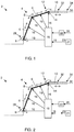
- crane movements are controlled in relation to a coordinate system having a base 28 of the crane as its origin. This is schematically illustrated by the coordinate systems shown in figures 3 and 4 close to the base 28 of the crane.
- the functionality of the at least one manoeuvre member 22 may be changed, i.e. the same manoeuvre member 22 may control one type of movement in the normal mode, and another type of movement in the tip tool mode.
- the tip tool 10 may be controlled to move along a straight linear path 30 from an initial point 32 to a target point 34 in response of an operator input 20 via one of said manoeuvre members 22.
- the crane tip tool 10 When the crane tip tool 10 is in the initial point 32 the crane tip tool 10 is controlled to be in an initial position having an orientation enabling movement of the tip tool along the straight linear path 30 from the initial point 32 to the target point 34.
- the crane is manoeuvred such that the crane tip tool is in an initial point before it is linearly moved to a target point.
- the crane tip tool is a fork.
- the initial position is then when the fork legs are in a correct position and have a correct orientation for moving the fork linearly such that the fork legs may be smoothly inserted into the receiving openings of a pallet 36 (see figures 3 and 4 ) to be picked up.
- the crane tip tool in the target point is illustrated as a dashed rectangle.
- the crane tip tool i.e. the fork
- the fork is in its target point.
- control unit 18 is configured to control movements of various parts of the crane 4, i.e. booms and/or joints and/or tool joint, to enable and perform movement of the tip tool 10 along the straight linear path 30.
- crane movement in the tip tool mode include that one or many joints of the crane may change angles, one or many boom sections of the crane are lengthened or shortened, and/or the crane base is rotated.
- the straight linear movement of the tip tool 10 is in a horizontal plane. This is illustrated in figures 1 and 2 .
- the straight linear movement of the tip tool 10 is in a plane inclined in relation to a horizontal plane.
- the crane is equipped with a tiltable fork.
- This embodiment opens up the possibility to pick and unpick a pallet which is on a slope, i.e. it facilitates also movements in the Y plane.
- the fork not only has a "pure" horizontal movement, but it may also follow the path in the Y plane pointed out by the inclination of the fork with respect to a horizontal plane.
- the coordinate system may be e.g. a Cartesian coordinate system, a polar coordinate system, or cylindrical and spherical coordinate systems.
- One coordinate system may be applied when in the normal mode of operation, e.g. a Cartesian coordinate system, and another when working in the tip tool mode of operation, e.g. an inclined Cartesian coordinate system or a spherical coordinate system.
- the present invention provides for an enhancement of a crane tip control to help the user to pick and place pallets and similar goods with a fork or similar at the crane tip.
- X-R or X-Z coordinate system functionality
- the mode of the crane control unit is manually or automatically changed and the crane tip tool and the tool joint, e.g. a rotator, follows the new path according X1.
- FIGS 3 and 4 are illustrated an example where the system rotates the crane (R), extends the boom (Ext) and rotates the Rotator (R1) when moving into the pallet.
- one or more manoeuvre members e.g. joysticks, or other control devices, at the operator's station may be used by an operator to move the crane, e.g. the boom, the crane tip, and the tool towards a target point.
- the manoeuvre members and control devices may be operably connected with the crane control unit of the working vehicle and located e.g. in the cabin or on the frame of the vehicle.
- a display may be connected to the control unit for showing information and data to the operator.
- the control unit is operably connected with various actuators associated with the boom and other components of the working vehicle.
- Control signals from the manoeuvre members and the control devices are communicated to the control unit, and the control unit is operable to responsively control the various actuators to rotate the boom, move and change the position of the boom and the tool, rotate the tool and operate the tool for performing work or grabbing with the arms of the tool.
- the crane control unit may be a programmable micro-processor-based device with a memory device and associated computer program code, for generating control signals to responsively control the various actuators.
- the computer program code may be in a form of a control program or a control algorithm, or appropriate computer software, running or being executed under the control of the control unit.
- the associated computer program code may be embodied on a computer readable medium.
- the control unit may have a distributed configuration with several subunits communicating with each other's.
- the actuators may be motors or cylinder actuators utilizing hydraulic energy and pressurized medium which is transmitted to the actuator by e.g. lines and flexible hoses.
- An apparatus for generating the hydraulic energy is placed in e.g. the frame or is operatively connected to the engine of the working vehicle. Hydraulic energy is distributed e.g. in the form of pressurized medium to the actuators via a control circuit provided with necessary valves and components for controlling the flow of the pressurized medium.
- Some actuators may utilize electric energy stored in an accumulator or generated with a generator operatively connected to the engine. The control circuit is controlled based on control signals from the control unit under the control of the operator or by an automatic control of the control unit.
Landscapes
- Engineering & Computer Science (AREA)
- Mechanical Engineering (AREA)
- Structural Engineering (AREA)
- Transportation (AREA)
- Civil Engineering (AREA)
- Life Sciences & Earth Sciences (AREA)
- Geology (AREA)
- Automation & Control Theory (AREA)
- Human Computer Interaction (AREA)
- Manufacturing & Machinery (AREA)
- Physics & Mathematics (AREA)
- General Physics & Mathematics (AREA)
- Robotics (AREA)
- Forklifts And Lifting Vehicles (AREA)
- Jib Cranes (AREA)
Claims (14)
- Arbeitsfahrzeug (2) mit einem Kran (4) mit mindestens einem ausfahrbaren Ausleger (6) und/oder mindestens einem Drehgelenk (8), wobei der Kran ein Kranspitzenwerkzeug (10) umfasst, das an einem distalen Kranspitzenende (12) angeordnet ist und über ein steuerbares Werkzeuggelenk (14) an dem Kran befestigt ist, wobei die Bewegungen des/der Ausleger(s) und/oder des/der Drehgelenke(s) des Krans und des Kranspitzenwerkzeugs durch Steuersignale (16) gesteuert werden, die durch eine Kransteuereinheit (18) in Abhängigkeit von Bedienereingaben (20), die durch mindestens ein Manövrierelement (22) empfangen werden, erzeugt werden,
wobei
der Kran (4) dazu ausgestaltet ist, in einem normalen Betriebsmodus und in einem Spitzenwerkzeugbetriebsmodus betrieben zu werden, und die Kransteuereinheit (18) dazu ausgestaltet ist, den Betriebsmodus des Krans in Abhängigkeit von einem Modussteuersignal (19) zu steuern,
dadurch gekennzeichnet, dass
das Arbeitsfahrzeug ein Sensorsystem (21) umfasst, das dazu fähig ist zu detektieren, wenn das Spitzenwerkzeug sich in einer Moduswechselposition befindet, in der es in einem Spitzenwerkzeugmodus gesteuert werden sollte, und das Sensorsystem (21) dazu ausgestaltet ist, ein Moduswechselhinweissignal (23) zu erzeugen, wenn das Spitzenwerkzeug (10) sich in der Moduswechselposition befindet, und wobei das Modussteuersignal (19) in Abhängigkeit von dem Moduswechselhinweissignal (23) erzeugt wird,
wobei in dem normalen Modus Kranbewegungen bezogen auf ein Koordinatensystem, das eine Basis (28) des Krans als seinen Ursprung aufweist, gesteuert werden,
und wobei in dem Spitzenwerkzeugmodus Kranbewegungen bezogen auf ein Koordinatensystem, welches das Werkzeuggelenk (14) als seinen Ursprung aufweist, gesteuert werden,
und wobei in dem Spitzenwerkzeugmodus das Spitzenwerkzeug (10) in Reaktion auf eine Bedienereingabe (20) über eines der Manövrierelemente (22) gesteuert wird. - Fahrzeug nach Anspruch 1, wobei das Moduswechselhinweissignal eines oder mehrere aus einem visuellen, akustischen oder haptischen Signal ist.
- Fahrzeug nach Anspruch 1 oder 2, wobei das Modussteuersignal (23) manuell durch einen Bediener erzeugt wird, vorzugsweise über einen Knopf, einen Berührungsbildschirm oder eine bewegungsempfindliche Vorrichtung.
- Fahrzeug nach Anspruch 1, wobei das Modulsteuersignal (19) automatisch erzeugt wird.
- Fahrzeug nach einem der Ansprüche 1-4, wobei das Sensorsystem (21) mindestens eine Kamera und/oder mindestens einen Sensor, der an dem Kran oder an dem Fahrzeug angeordnet ist, umfasst.
- Arbeitsfahrzeug (2) nach einem der Ansprüche 1-5, wobei an einem Anfangspunkt (32) das Kranspitzenwerkzeug (10) so gesteuert wird, dass es sich in einer Anfangsposition befindet, die eine Ausrichtung aufweist, die eine Bewegung des Spitzenwerkzeugs entlang eines geraden linearen Wegs (30) von dem Anfangspunkt (32) zu einem Zielpunkt (34) ermöglicht.
- Arbeitsfahrzeug (2) nach einem der Ansprüche 1-6, wobei die Kransteuereinheit (18) dazu ausgestaltet ist, Bewegungen von verschiedenen Teilen des Krans (4) zu steuern, um eine Bewegung des Spitzenwerkzeugs (10) entlang eines geraden linearen Wegs (30) zu ermöglichen und auszuführen.
- Arbeitsfahrzeug (2) nach Anspruch 7, wobei die gerade lineare Bewegung des Spitzenwerkzeugs (10) in einer horizontalen Ebene stattfindet.
- Arbeitsfahrzeug (2) nach Anspruch 7, wobei die gerade lineare Bewegung des Spitzenwerkzeugs (10) in einer Ebene stattfindet, die relativ zu einer horizontalen Ebene geneigt ist.
- Arbeitsfahrzeug (2) nach einem der Ansprüche 1-9, wobei das Manövrierelement (22) ein Joystick ist.
- Arbeitsfahrzeug (2) nach einem der Ansprüche 1-10, wobei das Spitzenwerkzeug (10) eine Gabel ist.
- Arbeitsfahrzeug (2) nach Anspruch 11, wobei die Moduswechselposition als optimale Position zum Einführen der Gabel zum Anheben einer Palette definiert ist.
- Arbeitsfahrzeug (2) nach einem der Ansprüche 1-11, wobei das Spitzenwerkzeug (10) ein Erntevorsatz, ein Fällkopf oder eine Holzrückezange ist.
- Arbeitsfahrzeug (2) nach einem der Ansprüche 1-12, wobei das Sensorsystem dazu ausgestaltet ist, ein zweites Moduswechselhinweissignal zu erzeugen, wenn das Spitzenwerkzeug (10) sich nicht mehr in der Moduswechselposition befindet.
Applications Claiming Priority (2)
| Application Number | Priority Date | Filing Date | Title |
|---|---|---|---|
| SE1651640A SE1651640A1 (sv) | 2016-12-14 | 2016-12-14 | A working vehicle including a crane |
| PCT/SE2017/051020 WO2018111169A1 (en) | 2016-12-14 | 2017-10-17 | A working vehicle including a crane |
Publications (2)
| Publication Number | Publication Date |
|---|---|
| EP3554983A1 EP3554983A1 (de) | 2019-10-23 |
| EP3554983B1 true EP3554983B1 (de) | 2020-09-23 |
Family
ID=60153405
Family Applications (1)
| Application Number | Title | Priority Date | Filing Date |
|---|---|---|---|
| EP17787670.3A Active EP3554983B1 (de) | 2016-12-14 | 2017-10-17 | Arbeitsfahrzeug mit einem kran |
Country Status (4)
| Country | Link |
|---|---|
| EP (1) | EP3554983B1 (de) |
| DK (1) | DK3554983T3 (de) |
| SE (1) | SE1651640A1 (de) |
| WO (1) | WO2018111169A1 (de) |
Families Citing this family (3)
| Publication number | Priority date | Publication date | Assignee | Title |
|---|---|---|---|---|
| WO2020076212A1 (en) * | 2018-10-12 | 2020-04-16 | Indexator Rotator System Ab | Arrangement for controlling a rotator by image sensing means |
| IT201900007917A1 (it) * | 2019-06-03 | 2020-12-03 | Da Ros Green S R L | Dispositivo per il supporto e per la rotazione su uno o piu’ assi di attrezzature agricole di vario genere |
| EP4650316A1 (de) * | 2024-05-14 | 2025-11-19 | Hiab AB | Krananordnung und verfahren zur steuerung davon |
Family Cites Families (5)
| Publication number | Priority date | Publication date | Assignee | Title |
|---|---|---|---|---|
| EP0397076A1 (de) * | 1989-05-11 | 1990-11-14 | Vickers Incorporated | Elektrohydraulisches System |
| US7856282B2 (en) | 2004-03-26 | 2010-12-21 | Incova Technologies, Inc. | Hydraulic system with coordinated multiple axis control of a machine member |
| FI20135085A7 (fi) | 2013-01-29 | 2014-07-30 | John Deere Forestry Oy | Menetelmä ja järjestelmä työkoneen puomiston ohjaamiseksi kärkiohjauksella |
| FI127305B (fi) * | 2014-04-29 | 2018-03-15 | John Deere Forestry Oy | Menetelmä ja järjestelmä metsäkoneen puomiston ohjaamiseksi |
| EP2987399B1 (de) | 2014-08-22 | 2021-07-21 | John Deere Forestry Oy | Verfahren und system zur ausrichtung eines werkzeugs |
-
2016
- 2016-12-14 SE SE1651640A patent/SE1651640A1/sv not_active Application Discontinuation
-
2017
- 2017-10-17 EP EP17787670.3A patent/EP3554983B1/de active Active
- 2017-10-17 WO PCT/SE2017/051020 patent/WO2018111169A1/en not_active Ceased
- 2017-10-17 DK DK17787670.3T patent/DK3554983T3/da active
Non-Patent Citations (1)
| Title |
|---|
| None * |
Also Published As
| Publication number | Publication date |
|---|---|
| WO2018111169A1 (en) | 2018-06-21 |
| EP3554983A1 (de) | 2019-10-23 |
| SE1651640A1 (sv) | 2018-06-15 |
| DK3554983T3 (da) | 2020-12-21 |
Similar Documents
| Publication | Publication Date | Title |
|---|---|---|
| US9568939B2 (en) | Tactile feedback for joystick position/speed controls | |
| US9272889B2 (en) | Tactile feedback for joystick position/speed controls | |
| CN110167336B (zh) | 用于控制作业机器中木材装卸装置的操作的方法和布置、以及林业机器 | |
| US9913437B2 (en) | Velocity-based control of end effector | |
| US10480541B2 (en) | Intelligent boom control with rapid system cycling | |
| DK179958B1 (en) | Crane and Method for Operating a Crane | |
| US12208723B2 (en) | Crane, a vehicle, and a method of the crane | |
| EP3554983B1 (de) | Arbeitsfahrzeug mit einem kran | |
| JP4657415B2 (ja) | 作業用具の協働制御を行うための装置及びその方法 | |
| EP3746391A1 (de) | Arbeitsbereichüberwachungssystem für hebemaschinen | |
| EP3556712B1 (de) | Sicherheitssystem | |
| EP2939530B1 (de) | Verfahren und system zur steuerung des krans einer forstmaschine | |
| EP0397076A1 (de) | Elektrohydraulisches System | |
| US12415710B2 (en) | Computer-controlled mobile crane | |
| US12435743B2 (en) | Controlling boom of work machine | |
| US20250353707A1 (en) | Crane arrangement and a method for control thereof | |
| US20260104702A1 (en) | Operations of articulating boom assemblies | |
| US20250276876A1 (en) | Control circuitry for a Crane, Crane, Remote Control unit for a crane and method to operate a crane | |
| EP3333114B1 (de) | Fahrzeug und verfahren für ein fahrzeug mit darstellung der maximalen lastbereichsbegrenzung | |
| CN107963197B (zh) | 锚泊车支臂的控制方法及控制系统 | |
| JP2025086286A (ja) | 移動式クレーン | |
| KR20250149500A (ko) | 건설기계의 자동 그랩 보조 시스템 및 건설기계의 자동 그랩 보조 제어 방법 | |
| JPH0336200A (ja) | ゴンドラの位置制御装置 | |
| JPH09239681A (ja) | マニピュレータの操作装置 | |
| JPH09300261A (ja) | マニュアルマニピュレータの操作入力装置 |
Legal Events
| Date | Code | Title | Description |
|---|---|---|---|
| STAA | Information on the status of an ep patent application or granted ep patent |
Free format text: STATUS: UNKNOWN |
|
| STAA | Information on the status of an ep patent application or granted ep patent |
Free format text: STATUS: THE INTERNATIONAL PUBLICATION HAS BEEN MADE |
|
| PUAI | Public reference made under article 153(3) epc to a published international application that has entered the european phase |
Free format text: ORIGINAL CODE: 0009012 |
|
| STAA | Information on the status of an ep patent application or granted ep patent |
Free format text: STATUS: REQUEST FOR EXAMINATION WAS MADE |
|
| 17P | Request for examination filed |
Effective date: 20190604 |
|
| AK | Designated contracting states |
Kind code of ref document: A1 Designated state(s): AL AT BE BG CH CY CZ DE DK EE ES FI FR GB GR HR HU IE IS IT LI LT LU LV MC MK MT NL NO PL PT RO RS SE SI SK SM TR |
|
| AX | Request for extension of the european patent |
Extension state: BA ME |
|
| DAV | Request for validation of the european patent (deleted) | ||
| DAX | Request for extension of the european patent (deleted) | ||
| GRAP | Despatch of communication of intention to grant a patent |
Free format text: ORIGINAL CODE: EPIDOSNIGR1 |
|
| STAA | Information on the status of an ep patent application or granted ep patent |
Free format text: STATUS: GRANT OF PATENT IS INTENDED |
|
| INTG | Intention to grant announced |
Effective date: 20200617 |
|
| GRAS | Grant fee paid |
Free format text: ORIGINAL CODE: EPIDOSNIGR3 |
|
| GRAA | (expected) grant |
Free format text: ORIGINAL CODE: 0009210 |
|
| STAA | Information on the status of an ep patent application or granted ep patent |
Free format text: STATUS: THE PATENT HAS BEEN GRANTED |
|
| AK | Designated contracting states |
Kind code of ref document: B1 Designated state(s): AL AT BE BG CH CY CZ DE DK EE ES FI FR GB GR HR HU IE IS IT LI LT LU LV MC MK MT NL NO PL PT RO RS SE SI SK SM TR |
|
| REG | Reference to a national code |
Ref country code: GB Ref legal event code: FG4D |
|
| REG | Reference to a national code |
Ref country code: CH Ref legal event code: EP |
|
| REG | Reference to a national code |
Ref country code: DE Ref legal event code: R096 Ref document number: 602017024282 Country of ref document: DE |
|
| REG | Reference to a national code |
Ref country code: IE Ref legal event code: FG4D |
|
| REG | Reference to a national code |
Ref country code: AT Ref legal event code: REF Ref document number: 1316214 Country of ref document: AT Kind code of ref document: T Effective date: 20201015 |
|
| REG | Reference to a national code |
Ref country code: DK Ref legal event code: T3 Effective date: 20201215 |
|
| PG25 | Lapsed in a contracting state [announced via postgrant information from national office to epo] |
Ref country code: FI Free format text: LAPSE BECAUSE OF FAILURE TO SUBMIT A TRANSLATION OF THE DESCRIPTION OR TO PAY THE FEE WITHIN THE PRESCRIBED TIME-LIMIT Effective date: 20200923 Ref country code: SE Free format text: LAPSE BECAUSE OF FAILURE TO SUBMIT A TRANSLATION OF THE DESCRIPTION OR TO PAY THE FEE WITHIN THE PRESCRIBED TIME-LIMIT Effective date: 20200923 Ref country code: BG Free format text: LAPSE BECAUSE OF FAILURE TO SUBMIT A TRANSLATION OF THE DESCRIPTION OR TO PAY THE FEE WITHIN THE PRESCRIBED TIME-LIMIT Effective date: 20201223 Ref country code: NO Free format text: LAPSE BECAUSE OF FAILURE TO SUBMIT A TRANSLATION OF THE DESCRIPTION OR TO PAY THE FEE WITHIN THE PRESCRIBED TIME-LIMIT Effective date: 20201223 Ref country code: GR Free format text: LAPSE BECAUSE OF FAILURE TO SUBMIT A TRANSLATION OF THE DESCRIPTION OR TO PAY THE FEE WITHIN THE PRESCRIBED TIME-LIMIT Effective date: 20201224 Ref country code: HR Free format text: LAPSE BECAUSE OF FAILURE TO SUBMIT A TRANSLATION OF THE DESCRIPTION OR TO PAY THE FEE WITHIN THE PRESCRIBED TIME-LIMIT Effective date: 20200923 |
|
| REG | Reference to a national code |
Ref country code: DE Ref legal event code: R082 Ref document number: 602017024282 Country of ref document: DE Representative=s name: MANITZ FINSTERWALD PATENT- UND RECHTSANWALTSPA, DE |
|
| PG25 | Lapsed in a contracting state [announced via postgrant information from national office to epo] |
Ref country code: RS Free format text: LAPSE BECAUSE OF FAILURE TO SUBMIT A TRANSLATION OF THE DESCRIPTION OR TO PAY THE FEE WITHIN THE PRESCRIBED TIME-LIMIT Effective date: 20200923 Ref country code: LV Free format text: LAPSE BECAUSE OF FAILURE TO SUBMIT A TRANSLATION OF THE DESCRIPTION OR TO PAY THE FEE WITHIN THE PRESCRIBED TIME-LIMIT Effective date: 20200923 |
|
| REG | Reference to a national code |
Ref country code: DE Ref legal event code: R082 Ref document number: 602017024282 Country of ref document: DE Representative=s name: MANITZ FINSTERWALD PATENT- UND RECHTSANWALTSPA, DE Ref country code: DE Ref legal event code: R081 Ref document number: 602017024282 Country of ref document: DE Owner name: HIAB AB, SE Free format text: FORMER OWNER: CARGOTEC PATENTER AB, LJUNGBY, SE |
|
| REG | Reference to a national code |
Ref country code: NL Ref legal event code: MP Effective date: 20200923 |
|
| REG | Reference to a national code |
Ref country code: LT Ref legal event code: MG4D |
|
| PG25 | Lapsed in a contracting state [announced via postgrant information from national office to epo] |
Ref country code: EE Free format text: LAPSE BECAUSE OF FAILURE TO SUBMIT A TRANSLATION OF THE DESCRIPTION OR TO PAY THE FEE WITHIN THE PRESCRIBED TIME-LIMIT Effective date: 20200923 Ref country code: RO Free format text: LAPSE BECAUSE OF FAILURE TO SUBMIT A TRANSLATION OF THE DESCRIPTION OR TO PAY THE FEE WITHIN THE PRESCRIBED TIME-LIMIT Effective date: 20200923 Ref country code: PT Free format text: LAPSE BECAUSE OF FAILURE TO SUBMIT A TRANSLATION OF THE DESCRIPTION OR TO PAY THE FEE WITHIN THE PRESCRIBED TIME-LIMIT Effective date: 20210125 Ref country code: CZ Free format text: LAPSE BECAUSE OF FAILURE TO SUBMIT A TRANSLATION OF THE DESCRIPTION OR TO PAY THE FEE WITHIN THE PRESCRIBED TIME-LIMIT Effective date: 20200923 Ref country code: LT Free format text: LAPSE BECAUSE OF FAILURE TO SUBMIT A TRANSLATION OF THE DESCRIPTION OR TO PAY THE FEE WITHIN THE PRESCRIBED TIME-LIMIT Effective date: 20200923 Ref country code: SM Free format text: LAPSE BECAUSE OF FAILURE TO SUBMIT A TRANSLATION OF THE DESCRIPTION OR TO PAY THE FEE WITHIN THE PRESCRIBED TIME-LIMIT Effective date: 20200923 |
|
| PG25 | Lapsed in a contracting state [announced via postgrant information from national office to epo] |
Ref country code: IS Free format text: LAPSE BECAUSE OF FAILURE TO SUBMIT A TRANSLATION OF THE DESCRIPTION OR TO PAY THE FEE WITHIN THE PRESCRIBED TIME-LIMIT Effective date: 20210123 Ref country code: PL Free format text: LAPSE BECAUSE OF FAILURE TO SUBMIT A TRANSLATION OF THE DESCRIPTION OR TO PAY THE FEE WITHIN THE PRESCRIBED TIME-LIMIT Effective date: 20200923 Ref country code: AL Free format text: LAPSE BECAUSE OF FAILURE TO SUBMIT A TRANSLATION OF THE DESCRIPTION OR TO PAY THE FEE WITHIN THE PRESCRIBED TIME-LIMIT Effective date: 20200923 Ref country code: ES Free format text: LAPSE BECAUSE OF FAILURE TO SUBMIT A TRANSLATION OF THE DESCRIPTION OR TO PAY THE FEE WITHIN THE PRESCRIBED TIME-LIMIT Effective date: 20200923 |
|
| REG | Reference to a national code |
Ref country code: CH Ref legal event code: PL |
|
| REG | Reference to a national code |
Ref country code: AT Ref legal event code: PC Ref document number: 1316214 Country of ref document: AT Kind code of ref document: T Owner name: HIAB AB, SE Effective date: 20210511 |
|
| REG | Reference to a national code |
Ref country code: DE Ref legal event code: R097 Ref document number: 602017024282 Country of ref document: DE |
|
| PG25 | Lapsed in a contracting state [announced via postgrant information from national office to epo] |
Ref country code: LU Free format text: LAPSE BECAUSE OF NON-PAYMENT OF DUE FEES Effective date: 20201017 Ref country code: SK Free format text: LAPSE BECAUSE OF FAILURE TO SUBMIT A TRANSLATION OF THE DESCRIPTION OR TO PAY THE FEE WITHIN THE PRESCRIBED TIME-LIMIT Effective date: 20200923 Ref country code: MC Free format text: LAPSE BECAUSE OF FAILURE TO SUBMIT A TRANSLATION OF THE DESCRIPTION OR TO PAY THE FEE WITHIN THE PRESCRIBED TIME-LIMIT Effective date: 20200923 |
|
| REG | Reference to a national code |
Ref country code: BE Ref legal event code: MM Effective date: 20201031 |
|
| PLBE | No opposition filed within time limit |
Free format text: ORIGINAL CODE: 0009261 |
|
| STAA | Information on the status of an ep patent application or granted ep patent |
Free format text: STATUS: NO OPPOSITION FILED WITHIN TIME LIMIT |
|
| PG25 | Lapsed in a contracting state [announced via postgrant information from national office to epo] |
Ref country code: LI Free format text: LAPSE BECAUSE OF NON-PAYMENT OF DUE FEES Effective date: 20201031 Ref country code: SI Free format text: LAPSE BECAUSE OF FAILURE TO SUBMIT A TRANSLATION OF THE DESCRIPTION OR TO PAY THE FEE WITHIN THE PRESCRIBED TIME-LIMIT Effective date: 20200923 Ref country code: CH Free format text: LAPSE BECAUSE OF NON-PAYMENT OF DUE FEES Effective date: 20201031 Ref country code: BE Free format text: LAPSE BECAUSE OF NON-PAYMENT OF DUE FEES Effective date: 20201031 |
|
| 26N | No opposition filed |
Effective date: 20210624 |
|
| PG25 | Lapsed in a contracting state [announced via postgrant information from national office to epo] |
Ref country code: IE Free format text: LAPSE BECAUSE OF NON-PAYMENT OF DUE FEES Effective date: 20201017 Ref country code: FR Free format text: LAPSE BECAUSE OF NON-PAYMENT OF DUE FEES Effective date: 20201123 |
|
| PG25 | Lapsed in a contracting state [announced via postgrant information from national office to epo] |
Ref country code: TR Free format text: LAPSE BECAUSE OF FAILURE TO SUBMIT A TRANSLATION OF THE DESCRIPTION OR TO PAY THE FEE WITHIN THE PRESCRIBED TIME-LIMIT Effective date: 20200923 Ref country code: MT Free format text: LAPSE BECAUSE OF FAILURE TO SUBMIT A TRANSLATION OF THE DESCRIPTION OR TO PAY THE FEE WITHIN THE PRESCRIBED TIME-LIMIT Effective date: 20200923 Ref country code: CY Free format text: LAPSE BECAUSE OF FAILURE TO SUBMIT A TRANSLATION OF THE DESCRIPTION OR TO PAY THE FEE WITHIN THE PRESCRIBED TIME-LIMIT Effective date: 20200923 |
|
| GBPC | Gb: european patent ceased through non-payment of renewal fee |
Effective date: 20211017 |
|
| PG25 | Lapsed in a contracting state [announced via postgrant information from national office to epo] |
Ref country code: MK Free format text: LAPSE BECAUSE OF FAILURE TO SUBMIT A TRANSLATION OF THE DESCRIPTION OR TO PAY THE FEE WITHIN THE PRESCRIBED TIME-LIMIT Effective date: 20200923 |
|
| PG25 | Lapsed in a contracting state [announced via postgrant information from national office to epo] |
Ref country code: GB Free format text: LAPSE BECAUSE OF NON-PAYMENT OF DUE FEES Effective date: 20211017 |
|
| PG25 | Lapsed in a contracting state [announced via postgrant information from national office to epo] |
Ref country code: NL Free format text: LAPSE BECAUSE OF NON-PAYMENT OF DUE FEES Effective date: 20200923 |
|
| REG | Reference to a national code |
Ref country code: DE Ref legal event code: R081 Ref document number: 602017024282 Country of ref document: DE Owner name: HIAB AB, SE Free format text: FORMER OWNER: HIAB AB, KISTA, SE |
|
| REG | Reference to a national code |
Ref country code: AT Ref legal event code: UEP Ref document number: 1316214 Country of ref document: AT Kind code of ref document: T Effective date: 20200923 |
|
| PGFP | Annual fee paid to national office [announced via postgrant information from national office to epo] |
Ref country code: DE Payment date: 20251028 Year of fee payment: 9 |
|
| PGFP | Annual fee paid to national office [announced via postgrant information from national office to epo] |
Ref country code: AT Payment date: 20251017 Year of fee payment: 9 |
|
| PGFP | Annual fee paid to national office [announced via postgrant information from national office to epo] |
Ref country code: DK Payment date: 20251024 Year of fee payment: 9 Ref country code: IT Payment date: 20251024 Year of fee payment: 9 |