EP3839552B1 - Dispositif de mesure de distances - Google Patents
Dispositif de mesure de distances Download PDFInfo
- Publication number
- EP3839552B1 EP3839552B1 EP19218321.8A EP19218321A EP3839552B1 EP 3839552 B1 EP3839552 B1 EP 3839552B1 EP 19218321 A EP19218321 A EP 19218321A EP 3839552 B1 EP3839552 B1 EP 3839552B1
- Authority
- EP
- European Patent Office
- Prior art keywords
- laser
- optical
- channel
- pumping
- thulium
- Prior art date
- Legal status (The legal status is an assumption and is not a legal conclusion. Google has not performed a legal analysis and makes no representation as to the accuracy of the status listed.)
- Active
Links
Images
Classifications
-
- G—PHYSICS
- G01—MEASURING; TESTING
- G01S—RADIO DIRECTION-FINDING; RADIO NAVIGATION; DETERMINING DISTANCE OR VELOCITY BY USE OF RADIO WAVES; LOCATING OR PRESENCE-DETECTING BY USE OF THE REFLECTION OR RERADIATION OF RADIO WAVES; ANALOGOUS ARRANGEMENTS USING OTHER WAVES
- G01S7/00—Details of systems according to groups G01S13/00, G01S15/00, G01S17/00
- G01S7/48—Details of systems according to groups G01S13/00, G01S15/00, G01S17/00 of systems according to group G01S17/00
- G01S7/483—Details of pulse systems
- G01S7/484—Transmitters
-
- G—PHYSICS
- G01—MEASURING; TESTING
- G01S—RADIO DIRECTION-FINDING; RADIO NAVIGATION; DETERMINING DISTANCE OR VELOCITY BY USE OF RADIO WAVES; LOCATING OR PRESENCE-DETECTING BY USE OF THE REFLECTION OR RERADIATION OF RADIO WAVES; ANALOGOUS ARRANGEMENTS USING OTHER WAVES
- G01S17/00—Systems using the reflection or reradiation of electromagnetic waves other than radio waves, e.g. lidar systems
- G01S17/02—Systems using the reflection of electromagnetic waves other than radio waves
- G01S17/06—Systems determining position data of a target
- G01S17/08—Systems determining position data of a target for measuring distance only
- G01S17/10—Systems determining position data of a target for measuring distance only using transmission of interrupted, pulse-modulated waves
-
- G—PHYSICS
- G01—MEASURING; TESTING
- G01S—RADIO DIRECTION-FINDING; RADIO NAVIGATION; DETERMINING DISTANCE OR VELOCITY BY USE OF RADIO WAVES; LOCATING OR PRESENCE-DETECTING BY USE OF THE REFLECTION OR RERADIATION OF RADIO WAVES; ANALOGOUS ARRANGEMENTS USING OTHER WAVES
- G01S7/00—Details of systems according to groups G01S13/00, G01S15/00, G01S17/00
- G01S7/48—Details of systems according to groups G01S13/00, G01S15/00, G01S17/00 of systems according to group G01S17/00
- G01S7/481—Constructional features, e.g. arrangements of optical elements
- G01S7/4814—Constructional features, e.g. arrangements of optical elements of transmitters alone
-
- G—PHYSICS
- G01—MEASURING; TESTING
- G01S—RADIO DIRECTION-FINDING; RADIO NAVIGATION; DETERMINING DISTANCE OR VELOCITY BY USE OF RADIO WAVES; LOCATING OR PRESENCE-DETECTING BY USE OF THE REFLECTION OR RERADIATION OF RADIO WAVES; ANALOGOUS ARRANGEMENTS USING OTHER WAVES
- G01S7/00—Details of systems according to groups G01S13/00, G01S15/00, G01S17/00
- G01S7/48—Details of systems according to groups G01S13/00, G01S15/00, G01S17/00 of systems according to group G01S17/00
- G01S7/481—Constructional features, e.g. arrangements of optical elements
- G01S7/4818—Constructional features, e.g. arrangements of optical elements using optical fibres
-
- H—ELECTRICITY
- H01—ELECTRIC ELEMENTS
- H01S—DEVICES USING THE PROCESS OF LIGHT AMPLIFICATION BY STIMULATED EMISSION OF RADIATION [LASER] TO AMPLIFY OR GENERATE LIGHT; DEVICES USING STIMULATED EMISSION OF ELECTROMAGNETIC RADIATION IN WAVE RANGES OTHER THAN OPTICAL
- H01S3/00—Lasers, i.e. devices using stimulated emission of electromagnetic radiation in the infrared, visible or ultraviolet wave range
- H01S3/005—Optical devices external to the laser cavity, specially adapted for lasers, e.g. for homogenisation of the beam or for manipulating laser pulses, e.g. pulse shaping
- H01S3/0078—Frequency filtering
-
- H—ELECTRICITY
- H01—ELECTRIC ELEMENTS
- H01S—DEVICES USING THE PROCESS OF LIGHT AMPLIFICATION BY STIMULATED EMISSION OF RADIATION [LASER] TO AMPLIFY OR GENERATE LIGHT; DEVICES USING STIMULATED EMISSION OF ELECTROMAGNETIC RADIATION IN WAVE RANGES OTHER THAN OPTICAL
- H01S3/00—Lasers, i.e. devices using stimulated emission of electromagnetic radiation in the infrared, visible or ultraviolet wave range
- H01S3/05—Construction or shape of optical resonators; Accommodation of active medium therein; Shape of active medium
- H01S3/06—Construction or shape of active medium
- H01S3/063—Waveguide lasers, i.e. whereby the dimensions of the waveguide are of the order of the light wavelength
- H01S3/067—Fibre lasers
- H01S3/06708—Constructional details of the fibre, e.g. compositions, cross-section, shape or tapering
- H01S3/06716—Fibre compositions or doping with active elements
-
- H—ELECTRICITY
- H01—ELECTRIC ELEMENTS
- H01S—DEVICES USING THE PROCESS OF LIGHT AMPLIFICATION BY STIMULATED EMISSION OF RADIATION [LASER] TO AMPLIFY OR GENERATE LIGHT; DEVICES USING STIMULATED EMISSION OF ELECTROMAGNETIC RADIATION IN WAVE RANGES OTHER THAN OPTICAL
- H01S3/00—Lasers, i.e. devices using stimulated emission of electromagnetic radiation in the infrared, visible or ultraviolet wave range
- H01S3/05—Construction or shape of optical resonators; Accommodation of active medium therein; Shape of active medium
- H01S3/06—Construction or shape of active medium
- H01S3/063—Waveguide lasers, i.e. whereby the dimensions of the waveguide are of the order of the light wavelength
- H01S3/067—Fibre lasers
- H01S3/0675—Resonators including a grating structure, e.g. distributed Bragg reflectors [DBR] or distributed feedback [DFB] fibre lasers
-
- H—ELECTRICITY
- H01—ELECTRIC ELEMENTS
- H01S—DEVICES USING THE PROCESS OF LIGHT AMPLIFICATION BY STIMULATED EMISSION OF RADIATION [LASER] TO AMPLIFY OR GENERATE LIGHT; DEVICES USING STIMULATED EMISSION OF ELECTROMAGNETIC RADIATION IN WAVE RANGES OTHER THAN OPTICAL
- H01S3/00—Lasers, i.e. devices using stimulated emission of electromagnetic radiation in the infrared, visible or ultraviolet wave range
- H01S3/05—Construction or shape of optical resonators; Accommodation of active medium therein; Shape of active medium
- H01S3/06—Construction or shape of active medium
- H01S3/063—Waveguide lasers, i.e. whereby the dimensions of the waveguide are of the order of the light wavelength
- H01S3/067—Fibre lasers
- H01S3/06754—Fibre amplifiers
-
- H—ELECTRICITY
- H01—ELECTRIC ELEMENTS
- H01S—DEVICES USING THE PROCESS OF LIGHT AMPLIFICATION BY STIMULATED EMISSION OF RADIATION [LASER] TO AMPLIFY OR GENERATE LIGHT; DEVICES USING STIMULATED EMISSION OF ELECTROMAGNETIC RADIATION IN WAVE RANGES OTHER THAN OPTICAL
- H01S3/00—Lasers, i.e. devices using stimulated emission of electromagnetic radiation in the infrared, visible or ultraviolet wave range
- H01S3/09—Processes or apparatus for excitation, e.g. pumping
- H01S3/091—Processes or apparatus for excitation, e.g. pumping using optical pumping
- H01S3/094—Processes or apparatus for excitation, e.g. pumping using optical pumping by coherent light
- H01S3/094003—Processes or apparatus for excitation, e.g. pumping using optical pumping by coherent light the pumped medium being a fibre
-
- H—ELECTRICITY
- H01—ELECTRIC ELEMENTS
- H01S—DEVICES USING THE PROCESS OF LIGHT AMPLIFICATION BY STIMULATED EMISSION OF RADIATION [LASER] TO AMPLIFY OR GENERATE LIGHT; DEVICES USING STIMULATED EMISSION OF ELECTROMAGNETIC RADIATION IN WAVE RANGES OTHER THAN OPTICAL
- H01S3/00—Lasers, i.e. devices using stimulated emission of electromagnetic radiation in the infrared, visible or ultraviolet wave range
- H01S3/09—Processes or apparatus for excitation, e.g. pumping
- H01S3/091—Processes or apparatus for excitation, e.g. pumping using optical pumping
- H01S3/094—Processes or apparatus for excitation, e.g. pumping using optical pumping by coherent light
- H01S3/094065—Single-mode pumping
-
- H—ELECTRICITY
- H01—ELECTRIC ELEMENTS
- H01S—DEVICES USING THE PROCESS OF LIGHT AMPLIFICATION BY STIMULATED EMISSION OF RADIATION [LASER] TO AMPLIFY OR GENERATE LIGHT; DEVICES USING STIMULATED EMISSION OF ELECTROMAGNETIC RADIATION IN WAVE RANGES OTHER THAN OPTICAL
- H01S3/00—Lasers, i.e. devices using stimulated emission of electromagnetic radiation in the infrared, visible or ultraviolet wave range
- H01S3/09—Processes or apparatus for excitation, e.g. pumping
- H01S3/091—Processes or apparatus for excitation, e.g. pumping using optical pumping
- H01S3/094—Processes or apparatus for excitation, e.g. pumping using optical pumping by coherent light
- H01S3/094076—Pulsed or modulated pumping
-
- H—ELECTRICITY
- H01—ELECTRIC ELEMENTS
- H01S—DEVICES USING THE PROCESS OF LIGHT AMPLIFICATION BY STIMULATED EMISSION OF RADIATION [LASER] TO AMPLIFY OR GENERATE LIGHT; DEVICES USING STIMULATED EMISSION OF ELECTROMAGNETIC RADIATION IN WAVE RANGES OTHER THAN OPTICAL
- H01S3/00—Lasers, i.e. devices using stimulated emission of electromagnetic radiation in the infrared, visible or ultraviolet wave range
- H01S3/09—Processes or apparatus for excitation, e.g. pumping
- H01S3/091—Processes or apparatus for excitation, e.g. pumping using optical pumping
- H01S3/094—Processes or apparatus for excitation, e.g. pumping using optical pumping by coherent light
- H01S3/0941—Processes or apparatus for excitation, e.g. pumping using optical pumping by coherent light of a laser diode
-
- H—ELECTRICITY
- H01—ELECTRIC ELEMENTS
- H01S—DEVICES USING THE PROCESS OF LIGHT AMPLIFICATION BY STIMULATED EMISSION OF RADIATION [LASER] TO AMPLIFY OR GENERATE LIGHT; DEVICES USING STIMULATED EMISSION OF ELECTROMAGNETIC RADIATION IN WAVE RANGES OTHER THAN OPTICAL
- H01S3/00—Lasers, i.e. devices using stimulated emission of electromagnetic radiation in the infrared, visible or ultraviolet wave range
- H01S3/14—Lasers, i.e. devices using stimulated emission of electromagnetic radiation in the infrared, visible or ultraviolet wave range characterised by the material used as the active medium
- H01S3/16—Solid materials
- H01S3/1601—Solid materials characterised by an active (lasing) ion
- H01S3/1603—Solid materials characterised by an active (lasing) ion rare earth
- H01S3/1608—Solid materials characterised by an active (lasing) ion rare earth erbium
-
- H—ELECTRICITY
- H01—ELECTRIC ELEMENTS
- H01S—DEVICES USING THE PROCESS OF LIGHT AMPLIFICATION BY STIMULATED EMISSION OF RADIATION [LASER] TO AMPLIFY OR GENERATE LIGHT; DEVICES USING STIMULATED EMISSION OF ELECTROMAGNETIC RADIATION IN WAVE RANGES OTHER THAN OPTICAL
- H01S3/00—Lasers, i.e. devices using stimulated emission of electromagnetic radiation in the infrared, visible or ultraviolet wave range
- H01S3/14—Lasers, i.e. devices using stimulated emission of electromagnetic radiation in the infrared, visible or ultraviolet wave range characterised by the material used as the active medium
- H01S3/16—Solid materials
- H01S3/1601—Solid materials characterised by an active (lasing) ion
- H01S3/1603—Solid materials characterised by an active (lasing) ion rare earth
- H01S3/1618—Solid materials characterised by an active (lasing) ion rare earth ytterbium
-
- H—ELECTRICITY
- H01—ELECTRIC ELEMENTS
- H01S—DEVICES USING THE PROCESS OF LIGHT AMPLIFICATION BY STIMULATED EMISSION OF RADIATION [LASER] TO AMPLIFY OR GENERATE LIGHT; DEVICES USING STIMULATED EMISSION OF ELECTROMAGNETIC RADIATION IN WAVE RANGES OTHER THAN OPTICAL
- H01S3/00—Lasers, i.e. devices using stimulated emission of electromagnetic radiation in the infrared, visible or ultraviolet wave range
- H01S3/23—Arrangements of two or more lasers not provided for in groups H01S3/02 - H01S3/22, e.g. tandem arrangements of separate active media
- H01S3/2308—Amplifier arrangements, e.g. MOPA
-
- H—ELECTRICITY
- H01—ELECTRIC ELEMENTS
- H01S—DEVICES USING THE PROCESS OF LIGHT AMPLIFICATION BY STIMULATED EMISSION OF RADIATION [LASER] TO AMPLIFY OR GENERATE LIGHT; DEVICES USING STIMULATED EMISSION OF ELECTROMAGNETIC RADIATION IN WAVE RANGES OTHER THAN OPTICAL
- H01S3/00—Lasers, i.e. devices using stimulated emission of electromagnetic radiation in the infrared, visible or ultraviolet wave range
- H01S3/09—Processes or apparatus for excitation, e.g. pumping
- H01S3/091—Processes or apparatus for excitation, e.g. pumping using optical pumping
- H01S3/094—Processes or apparatus for excitation, e.g. pumping using optical pumping by coherent light
- H01S3/094042—Processes or apparatus for excitation, e.g. pumping using optical pumping by coherent light of a fibre laser
-
- H—ELECTRICITY
- H01—ELECTRIC ELEMENTS
- H01S—DEVICES USING THE PROCESS OF LIGHT AMPLIFICATION BY STIMULATED EMISSION OF RADIATION [LASER] TO AMPLIFY OR GENERATE LIGHT; DEVICES USING STIMULATED EMISSION OF ELECTROMAGNETIC RADIATION IN WAVE RANGES OTHER THAN OPTICAL
- H01S3/00—Lasers, i.e. devices using stimulated emission of electromagnetic radiation in the infrared, visible or ultraviolet wave range
- H01S3/10—Controlling the intensity, frequency, phase, polarisation or direction of the emitted radiation, e.g. switching, gating, modulating or demodulating
- H01S3/11—Mode locking; Q-switching; Other giant-pulse techniques, e.g. cavity dumping
- H01S3/1123—Q-switching
-
- H—ELECTRICITY
- H01—ELECTRIC ELEMENTS
- H01S—DEVICES USING THE PROCESS OF LIGHT AMPLIFICATION BY STIMULATED EMISSION OF RADIATION [LASER] TO AMPLIFY OR GENERATE LIGHT; DEVICES USING STIMULATED EMISSION OF ELECTROMAGNETIC RADIATION IN WAVE RANGES OTHER THAN OPTICAL
- H01S3/00—Lasers, i.e. devices using stimulated emission of electromagnetic radiation in the infrared, visible or ultraviolet wave range
- H01S3/14—Lasers, i.e. devices using stimulated emission of electromagnetic radiation in the infrared, visible or ultraviolet wave range characterised by the material used as the active medium
- H01S3/16—Solid materials
- H01S3/1601—Solid materials characterised by an active (lasing) ion
- H01S3/1603—Solid materials characterised by an active (lasing) ion rare earth
- H01S3/161—Solid materials characterised by an active (lasing) ion rare earth holmium
-
- H—ELECTRICITY
- H01—ELECTRIC ELEMENTS
- H01S—DEVICES USING THE PROCESS OF LIGHT AMPLIFICATION BY STIMULATED EMISSION OF RADIATION [LASER] TO AMPLIFY OR GENERATE LIGHT; DEVICES USING STIMULATED EMISSION OF ELECTROMAGNETIC RADIATION IN WAVE RANGES OTHER THAN OPTICAL
- H01S3/00—Lasers, i.e. devices using stimulated emission of electromagnetic radiation in the infrared, visible or ultraviolet wave range
- H01S3/14—Lasers, i.e. devices using stimulated emission of electromagnetic radiation in the infrared, visible or ultraviolet wave range characterised by the material used as the active medium
- H01S3/16—Solid materials
- H01S3/1601—Solid materials characterised by an active (lasing) ion
- H01S3/1603—Solid materials characterised by an active (lasing) ion rare earth
- H01S3/1616—Solid materials characterised by an active (lasing) ion rare earth thulium
-
- H—ELECTRICITY
- H01—ELECTRIC ELEMENTS
- H01S—DEVICES USING THE PROCESS OF LIGHT AMPLIFICATION BY STIMULATED EMISSION OF RADIATION [LASER] TO AMPLIFY OR GENERATE LIGHT; DEVICES USING STIMULATED EMISSION OF ELECTROMAGNETIC RADIATION IN WAVE RANGES OTHER THAN OPTICAL
- H01S5/00—Semiconductor lasers
- H01S5/02—Structural details or components not essential to laser action
- H01S5/0206—Substrates, e.g. growth, shape, material, removal or bonding
- H01S5/021—Silicon based substrates
-
- H—ELECTRICITY
- H01—ELECTRIC ELEMENTS
- H01S—DEVICES USING THE PROCESS OF LIGHT AMPLIFICATION BY STIMULATED EMISSION OF RADIATION [LASER] TO AMPLIFY OR GENERATE LIGHT; DEVICES USING STIMULATED EMISSION OF ELECTROMAGNETIC RADIATION IN WAVE RANGES OTHER THAN OPTICAL
- H01S5/00—Semiconductor lasers
- H01S5/02—Structural details or components not essential to laser action
- H01S5/0206—Substrates, e.g. growth, shape, material, removal or bonding
- H01S5/0215—Bonding to the substrate
Definitions
- the invention relates to a device for measuring distances comprising a laser rangefinder, according to the preamble of claim 1.
- Such devices have diverse fields of application, for example in hunting, for landmark navigation on land or at sea, for aiming at objects, for acquiring and documenting geographic surroundings, as information device for hikers, etc. In addition to such civilian fields of application, such devices are also used in the military sector for navigation, observation, etc. It is important for the device to be robust and compact.
- the devices described here usually have measurement resolutions of the order of meters or, at best, decimeters, but have measurement ranges of several kilometers, for example of up to five, ten or twenty kilometers or even more.
- the devices can be designed for hand-held use by persons, i.e., for example, as field glasses or binoculars, monocular telescopes, spotting scopes, etc., but can by all means be attached to an equipment, a tripod or the like if necessary.
- a preferred device treated here is an observation devices comprising an optically transmissive light channel, i.e. being conventional optical devices in terms of the basic function thereof, in which optical radiation is directed directly from the observed target object into the eye of the observer.
- these can also be observation devices in which an observation image is recorded using a camera, the image is converted into electrical signals and the electrical signals are reproduced for the observer on a screen display.
- Devices with a screen allow the observation through an eyepiece, through which the recorded observation image can be observed.
- the observation path can comprise optical elements for beam shaping, beam deflection, mirroring information in and out, amplifying residual light, etc.
- this can relate to hand-held observation devices or distance-measuring observation devices which are generically embodied for use as a hand-held device, for example by appropriate handles, shaping, etc.
- the optical targeting enabled by the observation device also determines the direction of the distance measurement.
- the point to be measured is targeted by means of the transmissive light channel, for example by means of crosshairs in the observation channel of the device.
- Electro-optical distance meters or laser rangefinders (LRF) are emitting an optical signal, for example as optical radiation in the form of laser light pulses in the direction of the target object, the distance of which is intended to be determined.
- the surface of the target object casts back at least a portion of the emitted optical signal, usually in the form of a diffuse reflection.
- the cast-back optical radiation is converted into an electrical reception signal by a photosensitive detector element.
- the distance between the device and the target object can be determined with knowledge of the propagation speed of the optical signal and on the basis of the determined travel time between emission and reception of the signal (i.e. the travel time which light requires for covering the distance from the device to the target object and back again).
- There usually are one or more optical components for beam shaping, deflection, filtering, etc. - such as lens elements, wavelength filters, mirrors, etc. - in the optical transmission or reception path. Transmission and reception can be brought about coaxially using a single optical unit or separately using two separated optical units (e.g. arranged next to each other).
- the distance meter or the rangefinder is integrated in the observation device.
- the measurement requires sufficiently strong signal intensities, which can be detected by the receiver, of the returning reception signal.
- the signal power that can be emitted from the optoelectronic LRF considered here is restricted by physical and regulatory limits. Therefore, work is often undertaken with pulsed operation.
- the emitted optical signal is modulated in a pulse-like manner. Temporally short pulses with a high peak power are emitted, followed by pauses during which no light is emitted.
- the back reflected component of the pulses has a sufficiently high intensity to allow these to be evaluated in the presence of background disturbances and noise, in particular even in the presence of background light (sunlight, artificial illumination, etc.).
- the measurement target does not have special reflective target markers for the measurement (as is conventional in measurement rods, measurement prisms etc. used in surveying)
- the applied optical distance measurement signal must be embodied and set in the device design in such a way that a distance measurement is possible over the whole specified measurement range (or the range must be specified on the basis of the possibilities of the used signal).
- the signal information from a plurality of pulses is used cumulatively (in particular in-phase) for the evaluation.
- the signal-to-noise ratio (SNR) is improved in order thereby also to enable measurements in adverse conditions.
- the user targets a desired target using the observation device and then triggers the distance measuring process, for example by actuating a trigger button or the like.
- the measurement result, or further in-depth information derived therefrom, such as coordinates, etc. is displayed to said user, preferably directly by means of the observation channel of the observation device.
- the observation device can be equipped with means for determining geographic coordinates, such as a GPS, a constellation identifier, a direction measuring unit, a compass unit, tilt sensors or accelerometers, a night vision function, etc.
- a GPS Globalstar
- a constellation identifier e.g., a direction measuring unit
- a compass unit e.g., a direction measuring unit
- tilt sensors or accelerometers e.g. a night vision module
- a night vision function e.g. a night vision module
- EP 1 744 196 proposes, in an exemplary manner, several different embodiments for a generic observation device, for example for target marking, for military applications or for hunting purposes.
- US 7 724 354 B2 discloses a laser rangefinder with a single mode master laser diode of series FOL 15DCWD emitting laser light with a wavelength within the bandwidth of 1530nm to 1610nm.
- the light emitted from the master diode is coupled via an optical fiber to an amplifier with an actively amplifying Er/Yb co-doped fiber which is optically pumped by a pumping diode having a centre wavelength at about 945nm.
- the output laser light of the master laser diode is coupled into and amplified by the amplifying fiber.
- the output of the amplifying fiber includes optical noise due to amplified spontaneous emission (ASE) emitted in a broad spectral band.
- ASE amplified spontaneous emission
- a fiber-optical ASE filter in the form of a narrow band-pass filter is reducing the laser light of the laser rangefinder to light with the wavelength of the master laser diode within the bandwidth of 1530nm to 1610nm.
- the master diode and the pumping diode of the amplifying fiber are operated in a synchronized pulsed mode wherein the synchronisation is controlled by a pulse control unit.
- the laser light pulses are emitted by the laser rangefinder, reflected by the target object and received by the laser rangefinder. Travel time measurements between emission and reception are used to determine the distance between the laser rangefinder and the target object.
- the wavelength of the pumping laser light is preferably within the bandwidth of 1530nm to 1610nm.
- the thulium doped fiber laser acts as a wavelength converter from wavelengths in the range of 1550nm to wavelengths in the range of 2000nm.
- Laser rangefinders working with wavelengths above 1700nm are invisible to practically all current night vision devices and imagining sensors of cameras. Therefore, the inventive device with a laser rangefinder working in the range of 2000nm is not visible to current night vision devices and imagining sensors.
- the thulium and/or holmium doped fiber laser allows a highly-efficient operation with a high slope efficiency. As a monolithic all-fiber configuration, it is robust to external mechanical perturbations.
- the laser rangefinder with a thulium doped fiber laser can be designed in a compact way.
- the pumping of the laser can be continuous and therefore with a simplified design of controlling electronics.
- An embodiment with a continuously pumped laser and a Q-switch generating the pulse train has a low temperature sensitivity due to the fact of the FBGs (fiber Bragg gratings) low temperature shift of 0.01 nm/K.
- the laser emission wavelength is stable within a spectral range of 1 nm for a temperature range of 100°C without any active or passive control system.
- the thulium and/or holmium doped fiber laser arranged between two Bragg gratings is preferably an active co-doped fiber with holmium (Ho) and/or erbium (Er) and/or ytterbium (Yb) and/or of neodymium (Nd) and/or of praesodymium (Pr) having a gain spectral band. More generically the active fiber is doped with metallic ions.
- the pulsed pumping laser connected to the thulium and/or holmium doped fiber laser includes a single mode master laser diode, at least one amplifying Er/Yb co-doped fiber and a pumping diode wherein the at least one amplifying Er/Yb co-doped fiber is receiving pulsed light from the single mode master laser diode and is pumped by the synchronously pulsed pumping diode.
- the synchronous pulsing is ensuring selected signal pulse repetition rate.
- This pulsed pumping laser is a Master Oscillator Power Amplifier (MOPA) emitting high power pulses at a given repetition rate.
- MOPA Master Oscillator Power Amplifier
- the average output power of the gain-switched laser diode can range from -40 to -20 dBm.
- the TDFA should have a two-stage layout with moderate gain (typically in the range of 20-25 dB per stage) with intermediate ASE filtering, which is increasing cost, size and overall complexity.
- a preferred embodiment comprises an integrated coaxial laser pointer supporting easy bore sighting and allowing tactical pointing without the need of an additional pointer module.
- the laser pointer can be either Class 1 (eye safe) or Class 3B such as to comply with a specific maximum range specification for the device.
- the pointer is coupled to the laser rangefinder output.
- the pointer comprises a single mode pigtailed pointer diode emitting at a wavelength different from the laser rangefinder wavelength and coupled to the main optical path of the laser rangefinder by means of a fused Wavelength Division Multiplexer (WDM) or coupler, respectively.
- WDM Wavelength Division Multiplexer
- the Wavelength Division Multiplexer or coupler transmits the laser rangefinder and pointer beams along the same optical axis.
- the laser rangefinder can be used with or without pointer.
- the pointer light is preferably added to the fiber with the light of the laser rangefinder.
- a preferred embodiment of the laser range finder comprises 5 major components: a laser transmitter, optics for transmitting and receiving, a receiver, electronics for processing all information needed for distance measurements and a housing.
- the laser transmitter is described above.
- the optics are preferably made of glass optimized for short-wavelength infrared. Coating may be applied to improve the optical transmission at the laser rangefinder and pointer wavelength.
- the laser transmitter and transmitting optics are collimating the laser beam to have a minimal divergence.
- Receiver optics and the receiver are receiving the reflected laser pulses.
- the first optical observation channel can be a part of a binocular optical system with a first and a second binocular channel.
- the first binocular channel can comprise the first observation channel and the laser transmission channel, being used for transmission of the laser light towards the target.
- the second binocular channel can comprise the second observation channel and the laser receiver channel, being used for receiving of the laser light reflected at the target.
- the laser transmission channel can be coupled into the first observation channel and the laser receiver channel can be coupled into the second observation channel. Coupling can be provided by two beam splitters.
- the beam splitters can be semi-reflecting mirrors or prisms.
- At least the first optical observation channel is comprising a first opto-electronic display means for displaying range information.
- the observation device comprises an optically transmitting light channel, in which optical radiation is directed directly from the observed target object into the eye of the observer.
- the first observation channel, and if applicable the second observation channel respectively comprise a first and a second opto-electronic display means, respectively, for real-time processing and digitally displaying the image of the first and second observation channel, respectively, providing additional displaying functionalities, in particular for displaying range information and/or color rendering for enhancing contrast and/or for displaying image information detected outside of the visual wavelength range.
- the first observation channel comprises a first visual observation channel, in particular comprising the first opto-electronic display means, for real-time observing of the image plane of the first observation channel by eye, and an additional first electronic imaging channel comprising electronic imaging means, particularly CCD sensors and/or CMOS sensors and/or infrared detectors, for digitally receiving image information of the first observation channel and making said information available for the opto-electronic display means or for external post-processing.
- a first visual observation channel in particular comprising the first opto-electronic display means, for real-time observing of the image plane of the first observation channel by eye
- an additional first electronic imaging channel comprising electronic imaging means, particularly CCD sensors and/or CMOS sensors and/or infrared detectors, for digitally receiving image information of the first observation channel and making said information available for the opto-electronic display means or for external post-processing.
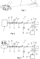
- Figure 1 shows an observation device 1, comprising a laser rangefinder (LRF) 2 which is used for targeting a target object 3 in a scenery and for determining the distance between the observation device 1 and the target object 3.
- the distance is measured along a laser axis 4 by emitting light pulses and determining the travel time to the target object 3 and back to the observation device 1.
- the observation device 1 has a central observation direction which corresponds to the laser axis 4.
- the observation is made with at least a first optical observation channel defining a first observation optical axis corresponding to the central observation direction.
- At least the first optical observation channel is receiving and imaging optical light rays onto an image plane for optical observations by the eye of an observer.
- Crosshairs in the at least one optical observation channel can be used to indicate the target object 3 to which the distance measurement is made.
- the first optical observation channel can comprise electronic imaging means, particularly CCD sensors and/or CMOS sensors and/or infrared detectors, for digitally receiving image information of the first observation channel and making said information available to the observer by a display means.
- electronic imaging means particularly CCD sensors and/or CMOS sensors and/or infrared detectors
- a user holds the observation device 1 and uses the generally magnifying observation channel to target the target object 3 and actuates a trigger in order to trigger a distance measurement.
- This opens a time window for the measurement.
- signal information from a plurality of pulse components cast back by the target object 3 are accumulated in order to determine the distance.
- the end of the time window can be defined by reaching a predetermined minimum number of pulses to be accumulated or by reaching a minimum number of pulses at which a sufficient threshold of the accumulated information is obtained or on the basis of predetermined temporal measurement duration.
- the determined distance information is thereupon provided to the user or a data processing unit.
- there can also be a graphical specification of the spatial position and/or an information about the accuracy of the distance.
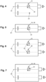
- FIGS 2 and 3 show schematic illustrations of laser rangefinders 2.
- the laser rangefinders 2 are comprising a laser transmission channel 5 and a laser receiver channel 6, wherein the laser light is emitted and received in directions along the laser axis 4.
- the laser rangefinders 2 are comprising a pumping laser 7 and a thulium and/or holmium doped fiber laser 8 with a thulium and/or holmium doped fiber section 9, two Bragg gratings 10 arranged on both sides of the thulium and/or holmium doped fiber section 9, a pumping connection 11 and an emitting connection 12 on opposite ends of the thulium and/or holmium doped fiber laser 8.
- the pumping laser 7 is connected with its output connector 13 to the pumping connection 11.
- the thulium and/or holmium doped fiber laser 8 is configured to emit laser light with a wavelength in the range of 1900nm to 2150nm at the emitting connection 12.
- a preferred pumping laser 7 is configured to emit laser light with a wavelength in the bandwidth of 1530nm to 1610nm.
- the pumping laser 7 of the embodiment of Figure 3 is a pulsed pumping laser emitting pulsed laser light.
- the generation of pulses is controlled by a pulse generator unit 14.
- the pumping laser 7 is generating pulse trains in the form of sets of pulses, wherein consecutive sets of pulses are separated in time.
- the pumped thulium and/or holmium doped fiber laser 8 is emitting corresponding pulse trains.
- emitting pulse trains by the thulium and/or holmium doped fiber laser 8 can be achieved by an optical component in the form of a Q-switch arranged at the emitting connection 12 of the thulium and/or holmium doped fiber laser 8.
- the Q-switch is configured to abruptly turning on and off the laser emission and thereby enabling emitting of pulse trains.
- the laser rangefinder 2 is comprising a fiber-optical filter 15 preferably arranged between the thulium and/or holmium doped fiber laser 8 and the emitting connection 12.
- the fiber-optical filter 15 is preferably a band-pass filter reducing the laser light of the laser rangefinder 2 to light with wavelengths in the range of 1900nm to 2150nm.
- the pumping laser 7 connected to the thulium and/or holmium doped fiber laser 8 includes a single mode master laser diode, at least one amplifying Er/Yb co-doped fiber and a pumping diode.
- the at least one amplifying Er/Yb co-doped fiber is receiving light from the single mode master laser diode and is pumped by the pumping diode.
- such a pumping laser 7 is configured as a pulsed pumping laser, wherein the single mode master laser diode and the pumping diode are synchronously pulsed.
- the pulsed pumping laser is preferably a Master Oscillator Power Amplifier (MOPA) configured to emit pulse trains suitable for the laser rangefinder wherein the pulse length is in the order of one ns to few tens of ns and the laser wavelength is around 1555nm at room temperature.
- MOPA Master Oscillator Power Amplifier
- the laser rangefinder comprises a Distributed Feed-Back (DFB) laser diode (LD) emitting laser light at a wavelength around 2000 nm and being connected to the pumping connection of the thulium and/or holmium doped fiber laser wherein the Distributed Feed-Back laser is configured to form a pulse train by gain switching or modulation, respectively, of the drive current applied to the 2000 nm laser diode.
- the pumping laser being embodied as a DFB-diode means single longitudinal mode operation of the laser rangefinder wherein the system represents a single-pass pulse generation system, so the source performance characteristics (pulse duration and repetition rate, pulse energy) can be independently controlled by a modification of the modulation current pulse train.
- the measuring point on the object 3 to which the distance measurement is made can be marked.
- the observation device 1 or preferably the laser rangefinder 2 comprises an integrated coaxial laser pointer 16.
- the laser pointer 16 preferably comprises a single mode pigtailed pointer diode emitting at a wavelength different from the laser rangefinder wavelength and coupled to the main optical path of the laser rangefinder 2 by means of a fused Wavelength Division Multiplexer (WDM) or coupler 17, respectively.
- WDM Wavelength Division Multiplexer
- the laser range finder 2 comprises a laser transmitter with the thulium and/or holmium doped fiber laser 8, optics for transmitting 18 and for receiving 19 laser light, a receiver 20 and electronics 21 for processing all information needed for distance measurements wherein the laser transmitter and transmitting optics 18 are collimating the laser beam and the receiver optics 19 and the receiver are receiving the reflected laser light.
- the first optical observation channel is a channel of a monocular or binocular optical system with at least a first and preferably a second optical channel.
- the channels for transmitting and for receiving laser light can be arranged in optical channels.
Landscapes
- Physics & Mathematics (AREA)
- Electromagnetism (AREA)
- Engineering & Computer Science (AREA)
- Plasma & Fusion (AREA)
- Optics & Photonics (AREA)
- Computer Networks & Wireless Communication (AREA)
- General Physics & Mathematics (AREA)
- Radar, Positioning & Navigation (AREA)
- Remote Sensing (AREA)
- Optical Radar Systems And Details Thereof (AREA)
Claims (14)
- Dispositif (1) de mesure de distances, comprenant un télémètre laser (2) pour la détermination de distances sur la base de temps de vol le long d'un axe laser (4) entre le dispositif (1) et un objet cible (3), le télémètre laser (2) comprenant un canal d'émission laser et un canal de réception laser,le télémètre laser (2) comprend un laser de pompage (7), un laser à fibre dopée au thulium et/ou à l'holmium (8) avec une section de fibre dopée au thulium et/ou à l'holmium (9) entre deux réseaux de Bragg (10) et une connexion d'émission (12), dans lequel le laser à fibre dopée au thulium et/ou à l'holmium (8) est pompé par le laser de pompage (7) et configuré pour délivrer une lumière laser présentant une longueur d'onde dans la plage de 1900 nm à 2150 nm,caractérisé en ce quele laser de pompage (7) connecté au laser à fibre dopée au thulium et/ou à l'holmium (8) comporte une diode laser maîtresse monomode, au moins une fibre co-dopée à l'Er/Yb d'amplification et une diode de pompage dans lequel l'au moins une fibre co-dopée à l'Er/Yb d'amplification reçoit de la lumière de la diode laser maîtresse monomode et est pompée par la diode de pompage.
- Dispositif (1) selon la revendication 1,
caractérisé en ce que
le laser de pompage (7) est configuré pour fournir une lumière laser présentant une longueur d'onde dans la largeur de bande de 1530 nm à 1610 nm. - Dispositif (1) selon la revendication 1 ou 2,
caractérisé en ce que
le laser de pompage (7) est pulsé et ainsi configuré pour générer des trains d'impulsions sous la forme d'ensembles d'impulsions, dans lequel des ensembles d'impulsions consécutifs sont séparés dans le temps dans lequel le laser à fibre dopée au thulium et/ou à l'holmium pompé (8) émet des trains d'impulsions correspondants. - Dispositif (1) selon la revendication 1 ou 2,
caractérisé en ce que
la connexion d'émission (12) du laser à fibre dopée au thulium et/ou à l'holmium (8) comprend un composant optique sous la forme d'un Q-switch dans lequel le Q-switch est configuré pour activer et désactiver brusquement l'émission laser et permettre ainsi l'émission de trains d'impulsions. - Dispositif (1) selon l'une quelconque des revendications 1 à 4,
caractérisé en ce que
le télémètre laser (2) comprend un filtre à fibre optique (15) agencé entre le laser à fibre dopée au thulium et/ou à l'holmium (8) et la connexion d'émission (12) dans lequel le filtre à fibre optique (15) est de préférence un filtre passe-bande réduisant la lumière laser du télémètre laser (2) à une lumière présentant des longueurs d'onde dans la plage de 1900 nm à 2150 nm. - Dispositif (1) selon l'une quelconque des revendications précédentes,
caractérisé en ce que
le laser de pompage (7) est un laser de pompage pulsé, dans lequel la diode laser maîtresse monomode et la diode de pompage sont pulsées de façon synchrone et le laser de pompage pulsé est de préférence un maître oscillateur et amplificateur de puissance (MOPA) configuré pour émettre des trains d'impulsions adaptés au télémètre laser dans lequel la longueur d'impulsion est de l'ordre d'un ns à quelques dizaines de ns et la longueur d'onde laser est d'environ 1555 nm à température ambiante. - Dispositif (1) selon la revendication 6,
caractérisé en ce que
un taux de répétition d'impulsion de la lumière laser émise est fixé par le taux de répétition d'impulsion du laser de pompage. - Dispositif (1) selon l'une quelconque des revendications précédentes,
caractérisé en ce que
le télémètre laser (2) comprend une diode laser (LD) à résonateur distribué (DFB) émettant une lumière laser à une longueur d'onde d'environ 2000 nm et connectée à une connexion de pompage (11) du laser à fibre dopée au thulium et/ou à l'holmium (8) dans lequel le laser à résonateur distribué est configuré pour former des trains d'impulsions par commutation ou modulation de gain, respectivement, du courant d'attaque appliqué à la diode laser de 2000 nm. - Dispositif (1) selon l'une quelconque des revendications précédentes,
caractérisé en ce que
le dispositif (1) comprend un pointeur laser coaxial intégré (16) dans lequel le pointeur laser (16) comprend de préférence une diode pointeuse avec fibre amorce monomode émettant à une longueur d'onde différente de la longueur d'onde du télémètre laser et couplée au trajet optique principal du télémètre laser (2) au moyen d'un multiplexeur par répartition en longueur d'onde fusionné (WDM) ou d'un coupleur (17), respectivement. - Dispositif (1) selon l'une quelconque des revendications précédentes,
caractérisé en ce que
le télémètre laser (2) comprend un émetteur laser ou une connexion d'émission (12), des composants optiques d'émission et de réception de lumière laser, un récepteur (20) et des composants électroniques (21) pour le traitement de toutes les informations nécessaires aux mesures de distance dans lequel l'émetteur laser et les composants optiques d'émission (18) collimatent le faisceau laser et les composants optiques de récepteur (19) et le récepteur reçoivent la lumière laser réfléchie. - Dispositif (1) selon l'une quelconque des revendications précédentes,
caractérisé en ce que
le dispositif (1) comprend au moins un premier canal d'observation optique pour des observations définissant un premier axe optique d'observation par réception et imagerie de rayons lumineux optiques pour des observations optiques par l'œil d'un observateur. - Dispositif (1) selon la revendication 11,
caractérisé en ce que
le premier canal d'observation optique est un canal d'un système optique monoculaire ou binoculaire présentant au moins un premier et de préférence un second canal optique. - Dispositif (1) selon la revendication 12,
caractérisé en ce que
le premier canal optique, comprenant le premier canal d'observation et le canal d'émission laser, utilisé pour l'émission de la lumière laser en direction de la cible (3), et le second canal binoculaire, comprenant un second canal d'observation et le canal de réception laser, utilisé pour la réception de la lumière laser réfléchie au niveau de l'objet cible (3), en particulier avec le canal d'émission laser couplé dans le premier canal d'observation et le canal récepteur laser couplé dans le second canal d'observation, en particulier dans lequel le couplage se fait par deux diviseurs de faisceaux ou éléments optiques (22), respectivement, les diviseurs de faisceaux étant notamment des miroirs ou prismes semi-réfléchissants. - Dispositif (1) selon l'une quelconque des revendications 11 à 13,
caractérisé en ce que
au moins le premier canal d'observation optique comprend un premier moyen d'affichage optoélectronique de préférence destiné à afficher des informations de portée, en particulier dans lequel au moins le premier canal d'observation optique comprend des moyens d'imagerie électronique, en particulier des capteurs CCD et/ou des capteurs CMOS et/ou des détecteurs infrarouges, pour la réception numérique d'informations d'image du premier canal d'observation et la mise à disposition desdites informations pour le premier moyen d'affichage optoélectronique et/ou pour un post-traitement externe.
Priority Applications (3)
| Application Number | Priority Date | Filing Date | Title |
|---|---|---|---|
| EP19218321.8A EP3839552B1 (fr) | 2019-12-19 | 2019-12-19 | Dispositif de mesure de distances |
| IL279412A IL279412B2 (en) | 2019-12-19 | 2020-12-13 | Distance measuring device |
| US17/122,026 US11867840B2 (en) | 2019-12-19 | 2020-12-15 | Device for measuring distances |
Applications Claiming Priority (1)
| Application Number | Priority Date | Filing Date | Title |
|---|---|---|---|
| EP19218321.8A EP3839552B1 (fr) | 2019-12-19 | 2019-12-19 | Dispositif de mesure de distances |
Publications (2)
| Publication Number | Publication Date |
|---|---|
| EP3839552A1 EP3839552A1 (fr) | 2021-06-23 |
| EP3839552B1 true EP3839552B1 (fr) | 2025-03-19 |
Family
ID=69411017
Family Applications (1)
| Application Number | Title | Priority Date | Filing Date |
|---|---|---|---|
| EP19218321.8A Active EP3839552B1 (fr) | 2019-12-19 | 2019-12-19 | Dispositif de mesure de distances |
Country Status (3)
| Country | Link |
|---|---|
| US (1) | US11867840B2 (fr) |
| EP (1) | EP3839552B1 (fr) |
| IL (1) | IL279412B2 (fr) |
Families Citing this family (6)
| Publication number | Priority date | Publication date | Assignee | Title |
|---|---|---|---|---|
| WO2021108568A1 (fr) * | 2019-11-27 | 2021-06-03 | Arizona Board Of Regents On Behalf Of The University Of Arizona | Transfert d'énergie efficace d'er3+ à ho3+ et dy3+ dans des matériaux de l'infrarouge moyen |
| EP4407817A4 (fr) * | 2021-09-22 | 2025-07-02 | Univ Valencia | Système de pompage pour laser à fibre optique à haute puissance dopé à l'holmium |
| CN114089357B (zh) * | 2021-10-01 | 2024-04-09 | 中国航空工业集团公司洛阳电光设备研究所 | 一种光电设备高精度激光测距方法 |
| CN114767236B (zh) * | 2022-06-24 | 2022-09-02 | 北京微刀医疗科技有限公司 | 光输出穿刺针、光感应穿刺针和穿刺距离测量系统 |
| CN117331974A (zh) * | 2023-09-26 | 2024-01-02 | 武汉锐科光纤激光技术股份有限公司 | 半导体激光器的泵浦源投料方法、系统、设备及存储介质 |
| CN119581975A (zh) * | 2024-11-07 | 2025-03-07 | 江苏师范大学 | 一种波长大于2.1微米的全光纤短腔掺铥光纤激光振荡器 |
Family Cites Families (10)
| Publication number | Priority date | Publication date | Assignee | Title |
|---|---|---|---|---|
| JP3940806B2 (ja) * | 1998-05-15 | 2007-07-04 | 株式会社ニコン | 光波測距装置 |
| US7724354B2 (en) | 2004-12-16 | 2010-05-25 | Vectronix Ag | Laser-system |
| ATE547732T1 (de) | 2005-07-14 | 2012-03-15 | Vectronix Ag | Multifunktions-beobachtungsgerät |
| US7593435B2 (en) * | 2007-10-09 | 2009-09-22 | Ipg Photonics Corporation | Powerful fiber laser system |
| TWI437783B (zh) * | 2009-12-31 | 2014-05-11 | Univ Nat Cheng Kung | 具有摻銩可飽和吸收q切換單元之脈衝雷射系統 |
| US8787410B2 (en) * | 2011-02-14 | 2014-07-22 | Imra America, Inc. | Compact, coherent, high brightness light sources for the mid and far IR |
| KR101386108B1 (ko) * | 2013-05-31 | 2014-04-16 | 광주과학기술원 | 광섬유를 이용한 광 증폭기 |
| CN105806308A (zh) * | 2014-12-29 | 2016-07-27 | 信泰光学(深圳)有限公司 | 双筒望远测距仪 |
| CN105514774A (zh) * | 2016-01-26 | 2016-04-20 | 中国人民解放军国防科学技术大学 | 纤芯-包层共抽运的2μm波段低阈值掺铥光纤激光器 |
| US10277002B2 (en) * | 2016-12-05 | 2019-04-30 | Bae Systems Information And Electronic Systems Integrations Inc. | Monolithic integrated seed and high power pump source |
-
2019
- 2019-12-19 EP EP19218321.8A patent/EP3839552B1/fr active Active
-
2020
- 2020-12-13 IL IL279412A patent/IL279412B2/en unknown
- 2020-12-15 US US17/122,026 patent/US11867840B2/en active Active
Also Published As
| Publication number | Publication date |
|---|---|
| EP3839552A1 (fr) | 2021-06-23 |
| IL279412A (en) | 2021-06-30 |
| US20210190916A1 (en) | 2021-06-24 |
| IL279412B1 (en) | 2024-12-01 |
| US11867840B2 (en) | 2024-01-09 |
| IL279412B2 (en) | 2025-04-01 |
Similar Documents
| Publication | Publication Date | Title |
|---|---|---|
| US11867840B2 (en) | Device for measuring distances | |
| US7847235B2 (en) | Laser obstacle ranging and display | |
| US8064491B2 (en) | Apparatus and method for generating short optical pulses | |
| US5831718A (en) | Portable laser range finder and digital compass assembly | |
| US7649616B2 (en) | Fiber laser ladar | |
| WO2020199136A1 (fr) | Système laser pour lidar | |
| RU2450399C2 (ru) | Способ генерации выходного лазерного света с требуемой характеристикой, лазерная система и транспортное средство, имеющее лазерную систему | |
| US11385054B2 (en) | Stabilized observation with LRF function | |
| US7379166B2 (en) | Combined laser altimeter and ground velocity measurement apparatus and a fiber optic filter edge detector of doppler shifts for use therein | |
| JP5135587B2 (ja) | 距離測定システム | |
| KR20120013515A (ko) | 광학측정장치의 아발란치 포토 다이오드 이득 보상 장치 | |
| JP2005091286A (ja) | レーザ測距装置 | |
| GB2251150A (en) | Laser radar system | |
| Ban et al. | A compact dual-wavelength fiber laser: some design aspects | |
| Perger et al. | Eyesafe diode laser rangefinder technology | |
| JP2026002293A (ja) | 投光器、および測定装置 | |
| Pallier et al. | Design and performance of a SWaP short-range fully fibered monostatic laser rangefinder | |
| JP2026002290A (ja) | 投光器、および測定装置 | |
| Papen | Remote Sensing using Fiber-Amplifier-Based Systems | |
| RO116930B1 (ro) | Telemetru portabil, miniaturizat, cu laser | |
| Séguin et al. | Airborne Obstacle Avoidance Lidar Using Q-Switched Erbium-Doped Fiber Lasers |
Legal Events
| Date | Code | Title | Description |
|---|---|---|---|
| PUAI | Public reference made under article 153(3) epc to a published international application that has entered the european phase |
Free format text: ORIGINAL CODE: 0009012 |
|
| STAA | Information on the status of an ep patent application or granted ep patent |
Free format text: STATUS: THE APPLICATION HAS BEEN PUBLISHED |
|
| AK | Designated contracting states |
Kind code of ref document: A1 Designated state(s): AL AT BE BG CH CY CZ DE DK EE ES FI FR GB GR HR HU IE IS IT LI LT LU LV MC MK MT NL NO PL PT RO RS SE SI SK SM TR |
|
| STAA | Information on the status of an ep patent application or granted ep patent |
Free format text: STATUS: REQUEST FOR EXAMINATION WAS MADE |
|
| 17P | Request for examination filed |
Effective date: 20211221 |
|
| RBV | Designated contracting states (corrected) |
Designated state(s): AL AT BE BG CH CY CZ DE DK EE ES FI FR GB GR HR HU IE IS IT LI LT LU LV MC MK MT NL NO PL PT RO RS SE SI SK SM TR |
|
| GRAP | Despatch of communication of intention to grant a patent |
Free format text: ORIGINAL CODE: EPIDOSNIGR1 |
|
| STAA | Information on the status of an ep patent application or granted ep patent |
Free format text: STATUS: GRANT OF PATENT IS INTENDED |
|
| RIC1 | Information provided on ipc code assigned before grant |
Ipc: H01S 5/02 20060101ALI20241010BHEP Ipc: H01S 3/16 20060101ALI20241010BHEP Ipc: H01S 3/094 20060101ALI20241010BHEP Ipc: H01S 3/115 20060101ALI20241010BHEP Ipc: G06F 3/01 20060101ALI20241010BHEP Ipc: H01S 3/00 20060101ALI20241010BHEP Ipc: H01S 3/11 20060101ALI20241010BHEP Ipc: H01S 3/067 20060101ALI20241010BHEP Ipc: G01S 17/10 20200101ALI20241010BHEP Ipc: G01S 7/484 20060101ALI20241010BHEP Ipc: G01S 7/481 20060101AFI20241010BHEP |
|
| INTG | Intention to grant announced |
Effective date: 20241108 |
|
| GRAS | Grant fee paid |
Free format text: ORIGINAL CODE: EPIDOSNIGR3 |
|
| GRAA | (expected) grant |
Free format text: ORIGINAL CODE: 0009210 |
|
| STAA | Information on the status of an ep patent application or granted ep patent |
Free format text: STATUS: THE PATENT HAS BEEN GRANTED |
|
| AK | Designated contracting states |
Kind code of ref document: B1 Designated state(s): AL AT BE BG CH CY CZ DE DK EE ES FI FR GB GR HR HU IE IS IT LI LT LU LV MC MK MT NL NO PL PT RO RS SE SI SK SM TR |
|
| REG | Reference to a national code |
Ref country code: GB Ref legal event code: FG4D |
|
| REG | Reference to a national code |
Ref country code: CH Ref legal event code: EP |
|
| REG | Reference to a national code |
Ref country code: IE Ref legal event code: FG4D |
|
| REG | Reference to a national code |
Ref country code: DE Ref legal event code: R096 Ref document number: 602019067432 Country of ref document: DE |
|
| PG25 | Lapsed in a contracting state [announced via postgrant information from national office to epo] |
Ref country code: RS Free format text: LAPSE BECAUSE OF FAILURE TO SUBMIT A TRANSLATION OF THE DESCRIPTION OR TO PAY THE FEE WITHIN THE PRESCRIBED TIME-LIMIT Effective date: 20250619 |
|
| PG25 | Lapsed in a contracting state [announced via postgrant information from national office to epo] |
Ref country code: FI Free format text: LAPSE BECAUSE OF FAILURE TO SUBMIT A TRANSLATION OF THE DESCRIPTION OR TO PAY THE FEE WITHIN THE PRESCRIBED TIME-LIMIT Effective date: 20250319 |
|
| REG | Reference to a national code |
Ref country code: LT Ref legal event code: MG9D |
|
| PG25 | Lapsed in a contracting state [announced via postgrant information from national office to epo] |
Ref country code: NO Free format text: LAPSE BECAUSE OF FAILURE TO SUBMIT A TRANSLATION OF THE DESCRIPTION OR TO PAY THE FEE WITHIN THE PRESCRIBED TIME-LIMIT Effective date: 20250619 |
|
| PG25 | Lapsed in a contracting state [announced via postgrant information from national office to epo] |
Ref country code: HR Free format text: LAPSE BECAUSE OF FAILURE TO SUBMIT A TRANSLATION OF THE DESCRIPTION OR TO PAY THE FEE WITHIN THE PRESCRIBED TIME-LIMIT Effective date: 20250319 |
|
| PG25 | Lapsed in a contracting state [announced via postgrant information from national office to epo] |
Ref country code: LV Free format text: LAPSE BECAUSE OF FAILURE TO SUBMIT A TRANSLATION OF THE DESCRIPTION OR TO PAY THE FEE WITHIN THE PRESCRIBED TIME-LIMIT Effective date: 20250319 |
|
| PG25 | Lapsed in a contracting state [announced via postgrant information from national office to epo] |
Ref country code: GR Free format text: LAPSE BECAUSE OF FAILURE TO SUBMIT A TRANSLATION OF THE DESCRIPTION OR TO PAY THE FEE WITHIN THE PRESCRIBED TIME-LIMIT Effective date: 20250620 Ref country code: BG Free format text: LAPSE BECAUSE OF FAILURE TO SUBMIT A TRANSLATION OF THE DESCRIPTION OR TO PAY THE FEE WITHIN THE PRESCRIBED TIME-LIMIT Effective date: 20250319 |
|
| REG | Reference to a national code |
Ref country code: NL Ref legal event code: MP Effective date: 20250319 |
|
| REG | Reference to a national code |
Ref country code: AT Ref legal event code: MK05 Ref document number: 1777373 Country of ref document: AT Kind code of ref document: T Effective date: 20250319 |
|
| PG25 | Lapsed in a contracting state [announced via postgrant information from national office to epo] |
Ref country code: NL Free format text: LAPSE BECAUSE OF FAILURE TO SUBMIT A TRANSLATION OF THE DESCRIPTION OR TO PAY THE FEE WITHIN THE PRESCRIBED TIME-LIMIT Effective date: 20250319 |
|
| PG25 | Lapsed in a contracting state [announced via postgrant information from national office to epo] |
Ref country code: SE Free format text: LAPSE BECAUSE OF FAILURE TO SUBMIT A TRANSLATION OF THE DESCRIPTION OR TO PAY THE FEE WITHIN THE PRESCRIBED TIME-LIMIT Effective date: 20250319 |
|
| PG25 | Lapsed in a contracting state [announced via postgrant information from national office to epo] |
Ref country code: SM Free format text: LAPSE BECAUSE OF FAILURE TO SUBMIT A TRANSLATION OF THE DESCRIPTION OR TO PAY THE FEE WITHIN THE PRESCRIBED TIME-LIMIT Effective date: 20250319 |
|
| PG25 | Lapsed in a contracting state [announced via postgrant information from national office to epo] |
Ref country code: PT Free format text: LAPSE BECAUSE OF FAILURE TO SUBMIT A TRANSLATION OF THE DESCRIPTION OR TO PAY THE FEE WITHIN THE PRESCRIBED TIME-LIMIT Effective date: 20250721 Ref country code: ES Free format text: LAPSE BECAUSE OF FAILURE TO SUBMIT A TRANSLATION OF THE DESCRIPTION OR TO PAY THE FEE WITHIN THE PRESCRIBED TIME-LIMIT Effective date: 20250319 |
|
| PG25 | Lapsed in a contracting state [announced via postgrant information from national office to epo] |
Ref country code: PL Free format text: LAPSE BECAUSE OF FAILURE TO SUBMIT A TRANSLATION OF THE DESCRIPTION OR TO PAY THE FEE WITHIN THE PRESCRIBED TIME-LIMIT Effective date: 20250319 Ref country code: IT Free format text: LAPSE BECAUSE OF FAILURE TO SUBMIT A TRANSLATION OF THE DESCRIPTION OR TO PAY THE FEE WITHIN THE PRESCRIBED TIME-LIMIT Effective date: 20250319 |
|
| PG25 | Lapsed in a contracting state [announced via postgrant information from national office to epo] |
Ref country code: AT Free format text: LAPSE BECAUSE OF FAILURE TO SUBMIT A TRANSLATION OF THE DESCRIPTION OR TO PAY THE FEE WITHIN THE PRESCRIBED TIME-LIMIT Effective date: 20250319 |
|
| PG25 | Lapsed in a contracting state [announced via postgrant information from national office to epo] |
Ref country code: EE Free format text: LAPSE BECAUSE OF FAILURE TO SUBMIT A TRANSLATION OF THE DESCRIPTION OR TO PAY THE FEE WITHIN THE PRESCRIBED TIME-LIMIT Effective date: 20250319 Ref country code: CZ Free format text: LAPSE BECAUSE OF FAILURE TO SUBMIT A TRANSLATION OF THE DESCRIPTION OR TO PAY THE FEE WITHIN THE PRESCRIBED TIME-LIMIT Effective date: 20250319 |
|
| PG25 | Lapsed in a contracting state [announced via postgrant information from national office to epo] |
Ref country code: RO Free format text: LAPSE BECAUSE OF FAILURE TO SUBMIT A TRANSLATION OF THE DESCRIPTION OR TO PAY THE FEE WITHIN THE PRESCRIBED TIME-LIMIT Effective date: 20250319 |
|
| PG25 | Lapsed in a contracting state [announced via postgrant information from national office to epo] |
Ref country code: SK Free format text: LAPSE BECAUSE OF FAILURE TO SUBMIT A TRANSLATION OF THE DESCRIPTION OR TO PAY THE FEE WITHIN THE PRESCRIBED TIME-LIMIT Effective date: 20250319 |
|
| PG25 | Lapsed in a contracting state [announced via postgrant information from national office to epo] |
Ref country code: IS Free format text: LAPSE BECAUSE OF FAILURE TO SUBMIT A TRANSLATION OF THE DESCRIPTION OR TO PAY THE FEE WITHIN THE PRESCRIBED TIME-LIMIT Effective date: 20250719 |
|
| REG | Reference to a national code |
Ref country code: DE Ref legal event code: R097 Ref document number: 602019067432 Country of ref document: DE |
|
| PGFP | Annual fee paid to national office [announced via postgrant information from national office to epo] |
Ref country code: GB Payment date: 20251229 Year of fee payment: 7 |
|
| PG25 | Lapsed in a contracting state [announced via postgrant information from national office to epo] |
Ref country code: DK Free format text: LAPSE BECAUSE OF FAILURE TO SUBMIT A TRANSLATION OF THE DESCRIPTION OR TO PAY THE FEE WITHIN THE PRESCRIBED TIME-LIMIT Effective date: 20250319 |
|
| PGFP | Annual fee paid to national office [announced via postgrant information from national office to epo] |
Ref country code: FR Payment date: 20251222 Year of fee payment: 7 |
|
| PLBE | No opposition filed within time limit |
Free format text: ORIGINAL CODE: 0009261 |
|
| STAA | Information on the status of an ep patent application or granted ep patent |
Free format text: STATUS: NO OPPOSITION FILED WITHIN TIME LIMIT |
|
| REG | Reference to a national code |
Ref country code: CH Ref legal event code: L10 Free format text: ST27 STATUS EVENT CODE: U-0-0-L10-L00 (AS PROVIDED BY THE NATIONAL OFFICE) Effective date: 20260128 |
|
| 26N | No opposition filed |
Effective date: 20251222 |
|
| PGFP | Annual fee paid to national office [announced via postgrant information from national office to epo] |
Ref country code: DE Payment date: 20251222 Year of fee payment: 7 |