EP3839402A1 - Plattenwärmetauscher - Google Patents
Plattenwärmetauscher Download PDFInfo
- Publication number
- EP3839402A1 EP3839402A1 EP21156850.6A EP21156850A EP3839402A1 EP 3839402 A1 EP3839402 A1 EP 3839402A1 EP 21156850 A EP21156850 A EP 21156850A EP 3839402 A1 EP3839402 A1 EP 3839402A1
- Authority
- EP
- European Patent Office
- Prior art keywords
- plates
- plate
- heat exchanger
- plate heat
- tool
- Prior art date
- Legal status (The legal status is an assumption and is not a legal conclusion. Google has not performed a legal analysis and makes no representation as to the accuracy of the status listed.)
- Granted
Links
Images


Classifications
-
- F—MECHANICAL ENGINEERING; LIGHTING; HEATING; WEAPONS; BLASTING
- F28—HEAT EXCHANGE IN GENERAL
- F28F—DETAILS OF HEAT-EXCHANGE AND HEAT-TRANSFER APPARATUS, OF GENERAL APPLICATION
- F28F3/00—Plate-like or laminated elements; Assemblies of plate-like or laminated elements
- F28F3/12—Elements constructed in the shape of a hollow panel, e.g. with channels
- F28F3/14—Elements constructed in the shape of a hollow panel, e.g. with channels by separating portions of a pair of joined sheets to form channels, e.g. by inflation
-
- B—PERFORMING OPERATIONS; TRANSPORTING
- B21—MECHANICAL METAL-WORKING WITHOUT ESSENTIALLY REMOVING MATERIAL; PUNCHING METAL
- B21D—WORKING OR PROCESSING OF SHEET METAL OR METAL TUBES, RODS OR PROFILES WITHOUT ESSENTIALLY REMOVING MATERIAL; PUNCHING METAL
- B21D53/00—Making other particular articles
- B21D53/02—Making other particular articles heat exchangers or parts thereof, e.g. radiators, condensers fins, headers
- B21D53/04—Making other particular articles heat exchangers or parts thereof, e.g. radiators, condensers fins, headers of sheet metal
- B21D53/045—Making other particular articles heat exchangers or parts thereof, e.g. radiators, condensers fins, headers of sheet metal by inflating partially united plates
-
- B—PERFORMING OPERATIONS; TRANSPORTING
- B23—MACHINE TOOLS; METAL-WORKING NOT OTHERWISE PROVIDED FOR
- B23K—SOLDERING OR UNSOLDERING; WELDING; CLADDING OR PLATING BY SOLDERING OR WELDING; CUTTING BY APPLYING HEAT LOCALLY, e.g. FLAME CUTTING; WORKING BY LASER BEAM
- B23K1/00—Soldering, e.g. brazing, or unsoldering
- B23K1/0008—Soldering, e.g. brazing, or unsoldering specially adapted for particular articles or work
- B23K1/0012—Brazing of heat exchangers
-
- B—PERFORMING OPERATIONS; TRANSPORTING
- B23—MACHINE TOOLS; METAL-WORKING NOT OTHERWISE PROVIDED FOR
- B23K—SOLDERING OR UNSOLDERING; WELDING; CLADDING OR PLATING BY SOLDERING OR WELDING; CUTTING BY APPLYING HEAT LOCALLY, e.g. FLAME CUTTING; WORKING BY LASER BEAM
- B23K1/00—Soldering, e.g. brazing, or unsoldering
- B23K1/008—Soldering within a furnace
-
- B—PERFORMING OPERATIONS; TRANSPORTING
- B23—MACHINE TOOLS; METAL-WORKING NOT OTHERWISE PROVIDED FOR
- B23K—SOLDERING OR UNSOLDERING; WELDING; CLADDING OR PLATING BY SOLDERING OR WELDING; CUTTING BY APPLYING HEAT LOCALLY, e.g. FLAME CUTTING; WORKING BY LASER BEAM
- B23K1/00—Soldering, e.g. brazing, or unsoldering
- B23K1/20—Preliminary treatment of work or areas to be soldered, e.g. in respect of a galvanic coating
-
- B—PERFORMING OPERATIONS; TRANSPORTING
- B23—MACHINE TOOLS; METAL-WORKING NOT OTHERWISE PROVIDED FOR
- B23K—SOLDERING OR UNSOLDERING; WELDING; CLADDING OR PLATING BY SOLDERING OR WELDING; CUTTING BY APPLYING HEAT LOCALLY, e.g. FLAME CUTTING; WORKING BY LASER BEAM
- B23K3/00—Tools, devices or special appurtenances for soldering, e.g. brazing, or unsoldering, not specially adapted for particular methods
- B23K3/08—Auxiliary devices therefor
- B23K3/087—Soldering or brazing jigs, fixtures or clamping means
-
- B—PERFORMING OPERATIONS; TRANSPORTING
- B23—MACHINE TOOLS; METAL-WORKING NOT OTHERWISE PROVIDED FOR
- B23P—METAL-WORKING NOT OTHERWISE PROVIDED FOR; COMBINED OPERATIONS; UNIVERSAL MACHINE TOOLS
- B23P15/00—Making specific metal objects by operations not covered by a single other subclass or a group in this subclass
- B23P15/26—Making specific metal objects by operations not covered by a single other subclass or a group in this subclass heat exchangers or the like
-
- F—MECHANICAL ENGINEERING; LIGHTING; HEATING; WEAPONS; BLASTING
- F28—HEAT EXCHANGE IN GENERAL
- F28D—HEAT-EXCHANGE APPARATUS, NOT PROVIDED FOR IN ANOTHER SUBCLASS, IN WHICH THE HEAT-EXCHANGE MEDIA DO NOT COME INTO DIRECT CONTACT
- F28D9/00—Heat-exchange apparatus having stationary plate-like or laminated conduit assemblies for both heat-exchange media, the media being in contact with different sides of a conduit wall
- F28D9/0031—Heat-exchange apparatus having stationary plate-like or laminated conduit assemblies for both heat-exchange media, the media being in contact with different sides of a conduit wall the conduits for one heat-exchange medium being formed by paired plates touching each other
- F28D9/0043—Heat-exchange apparatus having stationary plate-like or laminated conduit assemblies for both heat-exchange media, the media being in contact with different sides of a conduit wall the conduits for one heat-exchange medium being formed by paired plates touching each other the plates having openings therein for circulation of at least one heat-exchange medium from one conduit to another
- F28D9/0056—Heat-exchange apparatus having stationary plate-like or laminated conduit assemblies for both heat-exchange media, the media being in contact with different sides of a conduit wall the conduits for one heat-exchange medium being formed by paired plates touching each other the plates having openings therein for circulation of at least one heat-exchange medium from one conduit to another with U-flow or serpentine-flow inside conduits; with centrally arranged openings on the plates
-
- F—MECHANICAL ENGINEERING; LIGHTING; HEATING; WEAPONS; BLASTING
- F28—HEAT EXCHANGE IN GENERAL
- F28D—HEAT-EXCHANGE APPARATUS, NOT PROVIDED FOR IN ANOTHER SUBCLASS, IN WHICH THE HEAT-EXCHANGE MEDIA DO NOT COME INTO DIRECT CONTACT
- F28D9/00—Heat-exchange apparatus having stationary plate-like or laminated conduit assemblies for both heat-exchange media, the media being in contact with different sides of a conduit wall
- F28D9/0081—Heat-exchange apparatus having stationary plate-like or laminated conduit assemblies for both heat-exchange media, the media being in contact with different sides of a conduit wall the conduits for one heat-exchange medium being formed by a single plate-like element ; the conduits for one heat-exchange medium being integrated in one single plate-like element
-
- F—MECHANICAL ENGINEERING; LIGHTING; HEATING; WEAPONS; BLASTING
- F28—HEAT EXCHANGE IN GENERAL
- F28F—DETAILS OF HEAT-EXCHANGE AND HEAT-TRANSFER APPARATUS, OF GENERAL APPLICATION
- F28F21/00—Constructions of heat-exchange apparatus characterised by the selection of particular materials
- F28F21/08—Constructions of heat-exchange apparatus characterised by the selection of particular materials of metal
- F28F21/081—Heat exchange elements made from metals or metal alloys
- F28F21/084—Heat exchange elements made from metals or metal alloys from aluminium or aluminium alloys
-
- F—MECHANICAL ENGINEERING; LIGHTING; HEATING; WEAPONS; BLASTING
- F28—HEAT EXCHANGE IN GENERAL
- F28F—DETAILS OF HEAT-EXCHANGE AND HEAT-TRANSFER APPARATUS, OF GENERAL APPLICATION
- F28F3/00—Plate-like or laminated elements; Assemblies of plate-like or laminated elements
- F28F3/08—Elements constructed for building-up into stacks, e.g. capable of being taken apart for cleaning
- F28F3/086—Elements constructed for building-up into stacks, e.g. capable of being taken apart for cleaning having one or more openings therein forming tubular heat-exchange passages
-
- F—MECHANICAL ENGINEERING; LIGHTING; HEATING; WEAPONS; BLASTING
- F28—HEAT EXCHANGE IN GENERAL
- F28F—DETAILS OF HEAT-EXCHANGE AND HEAT-TRANSFER APPARATUS, OF GENERAL APPLICATION
- F28F9/00—Casings; Header boxes; Auxiliary supports for elements; Auxiliary members within casings
- F28F9/02—Header boxes; End plates
- F28F9/0246—Arrangements for connecting header boxes with flow lines
-
- B—PERFORMING OPERATIONS; TRANSPORTING
- B23—MACHINE TOOLS; METAL-WORKING NOT OTHERWISE PROVIDED FOR
- B23K—SOLDERING OR UNSOLDERING; WELDING; CLADDING OR PLATING BY SOLDERING OR WELDING; CUTTING BY APPLYING HEAT LOCALLY, e.g. FLAME CUTTING; WORKING BY LASER BEAM
- B23K2101/00—Articles made by soldering, welding or cutting
- B23K2101/04—Tubular or hollow articles
- B23K2101/14—Heat exchangers
-
- B—PERFORMING OPERATIONS; TRANSPORTING
- B23—MACHINE TOOLS; METAL-WORKING NOT OTHERWISE PROVIDED FOR
- B23K—SOLDERING OR UNSOLDERING; WELDING; CLADDING OR PLATING BY SOLDERING OR WELDING; CUTTING BY APPLYING HEAT LOCALLY, e.g. FLAME CUTTING; WORKING BY LASER BEAM
- B23K2103/00—Materials to be soldered, welded or cut
- B23K2103/08—Non-ferrous metals or alloys
- B23K2103/10—Aluminium or alloys thereof
-
- F—MECHANICAL ENGINEERING; LIGHTING; HEATING; WEAPONS; BLASTING
- F28—HEAT EXCHANGE IN GENERAL
- F28F—DETAILS OF HEAT-EXCHANGE AND HEAT-TRANSFER APPARATUS, OF GENERAL APPLICATION
- F28F2275/00—Fastening; Joining
- F28F2275/04—Fastening; Joining by brazing
-
- F—MECHANICAL ENGINEERING; LIGHTING; HEATING; WEAPONS; BLASTING
- F28—HEAT EXCHANGE IN GENERAL
- F28F—DETAILS OF HEAT-EXCHANGE AND HEAT-TRANSFER APPARATUS, OF GENERAL APPLICATION
- F28F2275/00—Fastening; Joining
- F28F2275/04—Fastening; Joining by brazing
- F28F2275/045—Fastening; Joining by brazing with particular processing steps, e.g. by allowing displacement of parts during brazing or by using a reservoir for storing brazing material
-
- F—MECHANICAL ENGINEERING; LIGHTING; HEATING; WEAPONS; BLASTING
- F28—HEAT EXCHANGE IN GENERAL
- F28F—DETAILS OF HEAT-EXCHANGE AND HEAT-TRANSFER APPARATUS, OF GENERAL APPLICATION
- F28F9/00—Casings; Header boxes; Auxiliary supports for elements; Auxiliary members within casings
- F28F9/001—Casings in the form of plate-like arrangements; Frames enclosing a heat exchange core
-
- Y—GENERAL TAGGING OF NEW TECHNOLOGICAL DEVELOPMENTS; GENERAL TAGGING OF CROSS-SECTIONAL TECHNOLOGIES SPANNING OVER SEVERAL SECTIONS OF THE IPC; TECHNICAL SUBJECTS COVERED BY FORMER USPC CROSS-REFERENCE ART COLLECTIONS [XRACs] AND DIGESTS
- Y02—TECHNOLOGIES OR APPLICATIONS FOR MITIGATION OR ADAPTATION AGAINST CLIMATE CHANGE
- Y02E—REDUCTION OF GREENHOUSE GAS [GHG] EMISSIONS, RELATED TO ENERGY GENERATION, TRANSMISSION OR DISTRIBUTION
- Y02E60/00—Enabling technologies; Technologies with a potential or indirect contribution to GHG emissions mitigation
- Y02E60/10—Energy storage using batteries
Definitions
- the invention relates to a plate heat exchanger.
- Plate heat exchangers are used, for example, to control the temperature of storage units for electrical energy in motor vehicles. It is known to use a large-area plate heat exchanger to control the temperature of all storage units that are arranged in a container. It is also known to control the temperature of individual modules of storage units. In particular, the storage units should be cooled during operation or during charging.
- Plate heat exchangers can also be used in many other technical areas and therefore have a wide range of dimensions.
- a plate heat exchanger which consists of two plate elements made of aluminum. There are bulges in the plate elements formed, which together form at least one cooling channel. The plate elements are then connected to one another by welding. This manufacturing process makes a separate forming tool necessary. In addition, welding is a complex and costly process, and the length of the weld seam also increases with increasing dimensions. The heat input is also disadvantageous for the strength of the material.
- a separating means is arranged between two metal sheets in order to define channel structures.
- the metal sheets are permanently connected to one another in a roll-bonding process.
- the areas treated with release agent are then inflated in order to form the channel structures.
- roll bonding however, the dimensional accuracy decreases with increasing plate size.
- choice of possible material pairings for the metal sheets is limited.
- the DE 2012 009 148 B4 discloses a component made of two layers of metal, at least one of which is profiled so that a cavity is formed between the two layers in order to convey a medium therein.
- the two layers can also be connected to one another by soldering. It is common practice to perform soldering in an oven through which the components are conveyed. In addition to the furnace, there is also a forming tool and special fixing racks for the components in the furnace, which entails high investment costs. In addition, the soldering process takes one to two hours, which is associated with long cycle times. This prolonged exposure to heat also has the disadvantage that magnesium precipitates occur in higher-strength aluminum alloys, which weaken the soldered connection. This means that these materials cannot be used for a plate heat exchanger.
- the prior art also includes an evaporator for evaporating a liquid, in particular for a waste heat recovery device of an internal combustion engine.
- the evaporator has a plurality of channel plate assemblies with a channel structure.
- a channel plate arrangement is formed from two plates in each case, one channel being formed by embossments, the are either formed only in one of the two plates or can be formed mirror-symmetrically in both plates. The impressions can be implemented, for example, by deep drawing or high pressure forming.
- the plates themselves are connected to one another, for example, by means of a soldering process.
- the DE 10 2016 107 946 A1 discloses a method for manufacturing a hollow component from a workpiece by means of a press. For this purpose, a workpiece is heated, placed in the tool and reshaping into a hollow body under gas pressure takes place in the tool, a protective gas being used and then the reshaped hollow body being immediately cooled in the tool.
- the plates are first heated to a first temperature together with the solder material arranged between the plates. This is chosen so that, although the material of at least one of the plates is easier to shape, the solder material has not yet melted.
- the first temperature is preferably 200.degree. C. to 550.degree. C., particularly preferably 300.degree. C. to 350.degree.
- a medium is passed between the plates under high pressure.
- the material of the plates can be deformed and rest against the inner surfaces of the cavities, creating hollow channel structures, while in the areas away from the cavities the plates remain in contact over the entire surface.
- the plates are held in position relative to one another. Due to the reproducible formation of precise channel structures in a tool, the method advantageously leads to a high-dimensional plate heat exchanger.
- the internal pressure reshaping is preferably carried out by means of an inert gas, for example nitrogen.
- the gas can be preheated.
- stiffness-increasing beads can also be introduced into the plate heat exchanger, which are not in fluid connection with the channel structures.
- the plates are then heated to a second temperature at which the solder material melts and the solder joint is created on the surfaces in contact. This creates a stable connection between the plates.
- the second temperature is advantageously 550 ° C to 650 ° C, preferably 600 ° C to 615 ° C.
- the plates are preferably heated uniformly to the second temperature in their areas provided with solder material, the temperature range ⁇ T across the plate being less than 50 K, preferably less than 10 K.
- An advantageous embodiment provides that the tool can be heated and that it is heated to the first temperature in the tool.
- the plates are heated up by means of thermal conduction, which leads to particularly rapid heating of the plates.
- the internal pressure forming can be started immediately when the first temperature is reached. In this way, cycle times can be shortened and additional devices for heating and transporting the panels are saved.
- the soldering connection of the plates is also carried out in the tool with the application of pressure from the tool.
- the plates preferably remain in the tool and are further heated to the second temperature. This also takes place in a very short time thanks to direct contact with the tool.
- the plates are mounted immovably relative to one another, so that no warping or shifting relative to one another is possible any longer. This also leads to a high degree of dimensional accuracy in the plate heat exchangers.
- the total duration of the process is a few minutes, which is considerably shorter than the usual dwell time in a soldering furnace of up to several hours.
- the tool is preferably preheated.
- it is preheated to a temperature of 550.degree. C. to 700.degree. C., preferably to a temperature of 600.degree. C. to 650.degree. C., particularly preferably to a temperature of 615.degree. C. to 625.degree.
- the plates and the brazing material are heated immediately, and the higher the temperature of the tool, the faster this heats up. This also contributes to a reduction in cycle times.
- sealing beads are provided adjacent to the cavities of the mold surfaces and / or around the tool in order to in the internal pressure forming, to seal the resulting channel structures.
- the plates are pressed against each other locally with high pressure, so that the internal pressure forming in the area of the cavities takes place precisely and with high dimensional accuracy.
- One plate is advantageously provided as a base plate, the other plate as a forming plate, and the channel structures are produced in the forming plate. This means that only one of the two plates is reshaped by internal pressure technology and the tool only has the necessary cavities in one tool part. This reduces the effort required to provide the tool. It is also possible to assign an additional function to the base plate, for example as a floor protection plate.
- the base plate preferably has a thickness of 0.5 to 5.0 millimeters, preferably 1.0 to 2.0 millimeters.
- the forming plate preferably has a thickness of 0.2 to 2.0 millimeters, preferably 0.8 to 1.0 millimeters.
- the thickness of the plates also depends on the material used, for example the specific alloy and / or pretreatment, and its properties.
- the plates consist of an aluminum alloy, preferably a high-strength aluminum alloy.
- the individual plates can consist of different alloys. These can be alloys that are typically used in soldering processes, for example alloys of the 3000 series, for example 3003 or 3005. However, they can also be alloys of the 5000 series. Alloys of the 6000 and 7000 series are generally considered to be difficult to solder, since magnesium precipitates form on the surface during the usually slow heating to the soldering temperature. The method used for production, however, enables the panels to be heated very quickly in the range of seconds or a few minutes, as opposed to several hours in conventional furnace soldering processes. This means that magnesium excretions can also be largely avoided. With that come aluminum alloys too for use in a plate heat exchanger are considered, which usually cannot be used. High-strength aluminum alloys in turn enable additional functions that the plate heat exchanger can take on, for example as a structural component.
- One of the two plates is preferably provided with a plated layer of solder. This makes handling of the plates easier and avoids an additional work step in order to apply the solder.
- the plates are advantageously arranged in such a way that the solder-plated plate is arranged at the top of the tool. During the soldering process, diffusion processes to the lower plate can take place with the aid of gravity and ensure a more stable connection.
- connection opening is produced in at least one of the plates. This can be done, for example, by punching, cutting or some other method.
- the connection opening serves to accommodate a connection element through which the cooling medium is later introduced or discharged.
- connection element is arranged on or in this connection opening.
- the connection element is preferably arranged on or in the connection opening.
- the connection element is particularly preferably arranged in the connection opening with a solder ring and / or a solder paste. In this way, the connection between the connection element and the associated plate can take place simultaneously with the soldering connection of the plates.
- a special embodiment provides that the medium for the internal pressure forming is introduced through the connection opening. This means that no additional connections are required for introducing the medium for internal pressure forming. The connections that are already available for introducing or discharging a cooling medium are used.
- a tool is advantageously used, the mold surfaces of which are provided with a coating in order to prevent the plates from sticking.
- a coating is, for example, a coating made of ceramic or other suitable materials.
- a separating agent is arranged between the plates and the mold surfaces of the tool in order to prevent the plates from sticking.
- the release agent can be, for example, a suitable fluid that is applied to the plates or the mold surfaces of the tool.
- it can be a sheet of foil that is inserted between the plate and the tool.
- it can be a wear plate that is also detachably fixed in the tool.
- the plates are subjected to higher pressure in order to fix the plates relative to one another and to generate a counterpressure to the medium introduced for internal pressure forming and to seal the channel structures in order to achieve high dimensional accuracy.
- the applied pressure is reduced, which is associated with the rising temperature, since high temperatures promote adhesion.
- the reduced pressure reduces normal stresses in the plates, which are a cause of the plate material sticking to the tool.
- Such a pressure variation can be made possible and supported by spring-mounted tools.
- the heating process can also be influenced by changing the heat conduction between the tool and the plates by varying the contact pressure.
- the plates After the plates have been connected by soldering, they are cooled down again.
- the cooling can take place by applying a cooling medium in or after removal from the tool.
- the plate heat exchanger can also be transferred to a cooling tool or a cooling rack. A combination of these or other process steps is also possible.
- the medium can be used for internal pressure forming for cooling or to support the cooling process.
- the medium is an inert gas, such as nitrogen, there is the additional advantage that the formation of an oxide layer is prevented.
- the cooling takes place more evenly and reduces deformation of the plates, which can be caused by internal stresses.
- the cooling time period between the technical soldering connection and the solder solidification is preferably shorter than 60 seconds, preferably shorter than 20 seconds, particularly preferably shorter than 10 seconds.
- This short cooling time means that eutectic structures with a longest dimension of less than 50 micrometers are formed in the solder layer. In conventional processes, these structures are significantly more coarse-grained and form elongated, needle-shaped structures with a length of 200 micrometers or more. These arise because in conventional soldering processes, such as furnace soldering, cooling can take several tens of minutes and the structures develop in this time. The fine-grain structure, however, means that the solder connection is significantly more stable and more fatigue-resistant.
- the fine-grained structure is formed and prevents premature cracks and gaping of the panels in this area, which is heavily loaded during operation. This significantly increases the service life of plate heat exchangers according to the invention.
- a heat treatment follows within less than 72 hours after cooling at a temperature of 140 ° C to 250 ° C for a period of 20 minutes to 24 hours, preferably from 20 minutes to 8 hours, particularly preferably from 20 minutes to 2 hours Hours.
- the strength properties of plate heat exchangers can advantageously be improved when using high-strength and ultra-high-strength aluminum alloys.
- the invention relates to a plate heat exchanger comprising two plates made of a metallic material, channel structures being formed in at least one plate and the plates being connected to one another by soldering apart from the channel structures, characterized in that eutectic structures are present in the solder layer a longest dimension of less than 50 micrometers.
- a plate heat exchanger comprising two plates made of a metallic material, channel structures being formed in at least one plate and the plates being connected to one another by soldering apart from the channel structures, characterized in that eutectic structures are present in the solder layer a longest dimension of less than 50 micrometers.
- the eutectic microstructures are preferably formed in solder accumulations in the transition area from the plates in contact with the channel structures. This area is exposed to particularly high loads during operation when a cooling medium is passed through the channel structures. Consequently, the formation of the structure at this point leads to an improved resistance to cracks and gaping in this sensitive area.
- the plate heat exchanger is preferably produced by a method as explained above.
- the plate heat exchanger is preferably manufactured using internal pressure technology.
- one of the plates is advantageously a base plate and one of the plates is a forming plate in which the channel structures are formed.
- the base plate preferably has a thickness of 0.5 to 5.0 millimeters, preferably 1.0 to 2.0 millimeters.
- the forming plate preferably has a thickness of 0.2 to 2.0 millimeters, preferably 0.8 to 1.0 millimeters.
- At least one of the plates has a yield point Rp0.2 in the tensile test of more than 100MPa, preferably more than 140MPa, particularly preferably more than 160MPa.
- a method for manufacturing a plate heat exchanger and the associated temperature profile are shown schematically.
- a base plate 1 and a forming plate 2 are provided. These are plates made of a 3000 aluminum alloy, for example an alloy with the designation 3003, 3005, 3903 or 3905.
- the thickness of the base plate 1 is 1.3 millimeters to 2.0 millimeters here.
- the thickness of the forming plate 2 is 0.5 millimeters to 1.5 millimeters.
- the forming plate 2 is clad with a solder material.
- a connection opening 3 is produced in the base plate 1.
- a connection element 4 together with a solder ring 5 is arranged on the connection opening 3.
- the base plate 1 and the forming plate 2 are brought into contact and placed in a preheated tool 6.
- the tool 6 is preheated to a temperature of about 630 ° C.
- the tool 6 comprises an upper tool 7 and a lower tool 8.
- cavities 10 are introduced which correspond to the intended channel structures of the plate heat exchanger to be produced.
- the lower tool 8 has receiving openings 11 for the connection element 4.
- Feed channels 12 for a medium 14 for internal pressure forming are connected to the receiving openings 11.
- an intended first temperature T 1 is reached, at which the internal pressure forming is started.
- the specific point in time depends on the temperature of the tool 6 and the material and thickness of the plates 1, 2.
- the time span between t0 and t1 is only a few seconds.
- the first temperature T 1 is 300 ° C. to 350 ° C. in this exemplary embodiment.
- the forming plate 2 is deformed until it comes into contact with the forming surface 9 of the upper tool 7.
- the tool 6 also applies a first pressure p 1 to the plates 1, 2 in order to counteract the internal pressure of the medium 14 and to seal the channel structures that are being formed. Sealing beads 13 are provided adjacent to the cavities 10 of the mold surfaces 9, which ensure that the forming process takes place exclusively in the region of the cavities 10. This ensures a high level of dimensional accuracy and forming accuracy.
- the plates 1, 2 are heated further.
- the solder material begins to melt at around 560 ° C.
- the second temperature T 2 is reached at a point in time t3.
- the time required for heating again depends on the materials used.
- the second temperature T 2 is here from 600 ° C to 615 ° C, preferably about 610 ° C.
- the soldering connection of the plates 1, 2 begins with the application of heat and a second pressure p 2 by the tool 6.
- the areas of the plates 1, 2 that are in contact over the entire surface are connected in a materially bonded manner.
- the connection element 4 is materially connected to the base plate 1 by the solder ring 5.
- the second pressure p 2 is lower than the first pressure p 1 in order to counteract any possible adhesion of the aluminum plates 1, 2 to the tool 6.
- the upper tool 7 and / or the lower tool 8 have a spring mounting.
- the soldering connection is completed at a point in time t4. Thereafter, the interconnected panels 1, 2 are cooled down to room temperature again (time t6). For this purpose, the plate heat exchanger 15 is removed from the tool 6 and either transferred to a cooling tool or stored in a cooling rack.
- the medium can be used for internal pressure forming for cooling or to support the cooling process.
- nitrogen as the inert medium, there is the additional advantage that the formation of an oxide layer is prevented.
- the cooling takes place more evenly and reduces deformation of the plates, which can be caused by internal stresses.
- the solder material has solidified.
- the time interval between t4 and t5 is preferably very short and is only a few minutes or even seconds.
- the short cooling time until the solder solidifies means that eutectic structures with a longest dimension of less than 50 micrometers are formed in the solder layer.
- Figure 3 contrasts two micrographs.
- the figure above shows an accumulation of solder in the transition area between the channel structures and the plates 1, 2 in contact, which would be found in the plane of the drawing to the right of the figure. This solder connection was created in a conventional furnace soldering process with long cooling times.
- Eutectic structures are formed which are elongated or needle-shaped and have a length extension of 200 micrometers and more.
- solder layer is shown in the lower figure, which was produced during the production of the plate heat exchanger according to the invention.
- the corresponding eutectic structures are formed in the dark areas. These are much finer-grained than in the figure above, with dimensions of less than 50 micrometers.
- the fine-grain structure means that the Solder connection is much more stable and fatigue-resistant. This is particularly important in the area of the transition between the channel structures and the soldered areas, since high loads occur there during operation, which can lead to cracks and a gaping of the two plates 1, 2.
Landscapes
- Engineering & Computer Science (AREA)
- Mechanical Engineering (AREA)
- Physics & Mathematics (AREA)
- Thermal Sciences (AREA)
- General Engineering & Computer Science (AREA)
- Heat-Exchange Devices With Radiators And Conduit Assemblies (AREA)
- Pressure Welding/Diffusion-Bonding (AREA)
- Cooling Or The Like Of Semiconductors Or Solid State Devices (AREA)
- Separation By Low-Temperature Treatments (AREA)
- Fuel Cell (AREA)
- Power Steering Mechanism (AREA)
Abstract
Description
- Die Erfindung betrifft einen Plattenwärmetauscher.
- Plattenwärmetauscher werden beispielsweise eingesetzt, um Speichereinheiten für elektrische Energie in Kraftfahrzeugen zu temperieren. Dabei ist es bekannt mit einem großflächigen Plattenwärmetauscher alle Speichereinheiten, die einem Behälter angeordnet sind, zu temperieren. Ebenso ist es bekannt, einzelne Module von Speichereinheiten zu temperieren. Insbesondere sollen die Speichereinheiten im Betrieb oder beim Aufladen gekühlt werden.
- Plattenwärmetauscher sind darüber hinaus in vielen anderen technischen Bereichen einsetzbar und weisen daher eine große Bandbreite an Abmessungen auf.
- Aus der
DE 10 2010 051 106 A1 ist ein Plattenwärmetauscher bekannt, der aus zwei Plattenelementen aus Aluminium besteht. In die Plattenelemente sind Ausbuchtungen eingeformt, die miteinander mindestens einen Kühlkanal bilden. Die Plattenelemente werden danach schweißtechnisch miteinander verbunden. Dieses Herstellungsverfahren macht ein separates Umformwerkzeug notwendig. Zudem ist Schweißen ein aufwändiges und kostspieliges Verfahren, wobei zudem mit steigenden Abmessungen auch die Länge der Schweißnaht ansteigt. Auch der Wärmeeintrag ist nachteilig für die Festigkeit des Materials. - In der
DE 10 2014 219 812 A1 wird ein Verfahren offenbart, bei dem zwischen zwei Metallblechen ein Trennmittel angeordnet, um Kanalstrukturen zu definieren. Die Metallbleche werden in einem Roll-Bonding-Verfahren unlösbar miteinander verbunden. Anschließend werden die mit Trennmittel behandelten Bereiche aufgeblasen, um die Kanalstrukturen auszubilden. Beim Roll-Bonding sinkt aber die Maßhaltigkeit mit zunehmender Plattengröße. Zudem ist die Auswahl an möglichen Materialpaarungen für die Metallbleche beschränkt. - Schließlich ist es noch bekannt, bei der Herstellung eines Plattenwärmetauschers die beiden Platten miteinander zu verlöten. Die
DE 2012 009 148 B4 offenbart ein Bauteil aus zwei Schichten aus Metall, von denen mindestens eine profiliert ist, so dass zwischen den beiden Schichten ein Hohlraum gebildet wird, um darin ein Medium zu fördern. Die beiden Schichten können auch löttechnisch miteinander verbunden werden. Es ist üblich, das Löten in einem Ofen durchzuführen, durch den die Bauteile gefördert werden. Neben den Ofen treten auch ein Umformwerkzeug und spezielle Fixiergestelle für die Bauteile im Ofen, was hohe Investitionskosten mit sich bringt. Zudem dauert der Lötvorgang ein bis zwei Stunden, was mit langen Taktzeiten einhergeht. Diese langandauernde Wärmebeaufschlagung hat zudem den Nachteil, dass bei höherfesten Aluminium-Legierungen Magnesium-Ausscheidungen auftreten, die die Lotverbindung schwächen. Damit sind diese Materialien für einen Plattenwärmetauscher nicht verwendbar. - Durch die
DE 10 2011 077 154 A1 zählt des Weiteren ein Verdampfer zum Verdampfen einer Flüssigkeit, insbesondere für eine Abwärmenutzungsvorrichtung einer Brennkraftmaschine, zum Stand der Technik. Der Verdampfer weist mehrere Kanalplattenanordnungen mit einer Kanalstruktur auf. Eine Kanalplattenanordnung ist aus jeweils zwei Platten gebildet, wobei ein Kanal durch Einprägungen gebildet ist, die entweder nur in einer der beiden Platten ausgebildet sind oder in beiden Platten spiegelsymmetrisch ausgebildet sein können. Die Einprägungen können beispielsweise durch Tiefziehen oder durch Hochdruckumformung realisiert sein. Die Platten selbst sind beispielsweise mittels eines Lötverfahrens miteinander verbunden. - Die
DE 10 2016 107 946 A1 offenbart ein Verfahren zum Fertigen eines hohlen Bauteils aus einem Werkstück mittels einer Presse. Hierzu wird ein Werkstück erwärmt, in das Werkzeug eingelegt und im Werkzeug ein Umformen zum Hohlkörper unter Gasdruck erfolgt, wobei ein Schutzgas verwendet wird und anschließend der umgeformte Hohlkörper in dem Werkzeug unmittelbar abgekühlt wird. - Es ist die Aufgabe der Erfindung, einen Plattenwärmetauscher zur Verfügung zu stellen, der kostengünstig und hinsichtlich der Materialien flexibel herstellbar ist sowie eine lange Lebensdauer aufweist.
- Diese Aufgabe wird gelöst durch einen Plattenwärmetauscher mit den Merkmalen des Anspruchs 1.
- Besondere Ausgestaltungen der Erfindung sind Gegenstand der abhängigen Ansprüche.
- Ein erfindungsgemäßer Plattenwärmetauscher wird mittels folgenden Schritten hergestellt:
- Bereitstellen zweier Platten aus einem metallischen Werkstoff, wobei die Platten in Anlage gebracht werden, wobei ein Lotwerkstoff zwischen den Platten angeordnet wird,
- Aufheizen der Platten auf eine erste Temperatur,
- Einlegen der Platten in ein Werkzeug, dessen Formflächen Kavitäten für vorgesehenen Kanalstrukturen aufweisen,
- Ausbilden von Kanalstrukturen durch lokale innendrucktechnische Umformung zumindest einer Platte unter Beaufschlagung mit Druck durch das Werkzeug,
- Aufheizen der Platten auf eine zweite Temperatur,
- Löttechnisches Verbinden der Platten an den in Anlage befindlichen Flächen,
- Abkühlen der Platten (1, 2) nach dem löttechnischen Verbinden, wobei die Abkühlzeitspanne zwischen dem löttechnischen Verbinden und der Loterstarrung kürzer als 60 Sekunden, bevorzugt kürzer als 20 Sekunden, besonders bevorzugt kürzer als 10 Sekunden ist.
- Die Platten werden zusammen mit dem zwischen den Platten angeordneten Lotwerkstoff zunächst auf eine erste Temperatur erwärmt. Diese ist so gewählt, dass zwar das Material zumindest einer der Platten leichter formbar ist, aber der Lotwerkstoff noch nicht geschmolzen ist. Bevorzugt beträgt die erste Temperatur 200°C bis 550°C, besonders bevorzugt 300°C bis 350°C.
- Beim innendrucktechnischen Umformen wird ein Medium unter hohem Druck zwischen die Platten geleitet. Im Bereich der Kavitäten kann sich das Material der Platten verformen und an die Innenoberflächen der Kavitäten anlegen, wodurch hohle Kanalstrukturen geschaffen werden, während in den Bereichen abseits der Kavitäten die Platten vollflächig in Anlage bleiben. Gleichzeitig werden die Platten relativ zueinander in Position gehalten. Das Verfahren führt durch die reproduzierbare Ausbildung präziser Kanalstrukturen in einem Werkzeug in vorteilhafter Weise zu einem hochmaßhaltigen Plattenwärmetauscher.
- Die innendrucktechnische Umformung erfolgt bevorzugt mittels eines inerten Gases, beispielsweise Stickstoff. Das Gas kann dabei vorgewärmt sein.
- Beim Ausbilden der Kanalstrukturen können auch steifigkeitserhöhende Sicken in den Plattenwärmetauscher eingebracht werden, die nicht in Fluidverbindung zu den Kanalstrukturen stehen.
- Die Platten werden nachfolgend auf eine zweite Temperatur erwärmt, bei der der Lotwerkstoff aufschmilzt und die Lotverbindung an den in Anlage befindlichen Flächen entsteht. Damit wird eine stabile Verbindung zwischen den Platten geschaffen. Vorteilhafterweise beträgt die zweite Temperatur 550°C bis 650°C, bevorzugt 600°C bis 615°C.
- Bevorzugt werden die Platten in ihren mit Lotwerkstoff versehenen Bereichen gleichmäßig auf die zweite Temperatur aufgeheizt werden, wobei die Temperaturspanne ΔT über die Platte hinweg kleiner als 50 K, bevorzugt kleiner als 10 K beträgt.
- Eine vorteilhafte Ausgestaltung sieht vor, dass das Werkzeug beheizbar ist und das Aufheizen auf die erste Temperatur in dem Werkzeug erfolgt. Das Aufheizen der Platten erfolgt mittels Wärmeleitung, was zu einer besonders zügigen Erwärmung der Platten führt. Weiterhin kann mit der innendrucktechnischen Umformung unmittelbar beim Erreichen der ersten Temperatur begonnen werden. Somit kann eine Verkürzung der Taktzeiten erreicht werden und zusätzliche Vorrichtungen zum Erwärmen und zum Transport der Platten werden eingespart.
- Weiterhin ist es vorteilhaft, wenn das löttechnische Verbinden der Platten ebenfalls in dem Werkzeug erfolgt unter Beaufschlagung mit Druck durch das Werkzeug. Das bedeutet, dass die Platten nach dem innendrucktechnischen Umformen bevorzugt in dem Werkzeug verbleiben und weiter auf die zweite Temperatur aufgeheizt werden. Auch dies erfolgt durch den unmittelbaren Kontakt mit dem Werkzeug in einer sehr kurzen Zeit. Vorteilhaft ist hier auch, dass die Platten unverrückbar relativ zueinander gelagert sind, so dass kein Verzug oder Verschieben relativ zueinander mehr möglich sind. Dies führt ebenfalls zu einer hohen Maßhaltigkeit bei den Plattenwärm etauschern.
- Die Gesamtdauer des Verfahrens beträgt wenige Minuten, was beträchtlich kürzer ist als die übliche Verweildauer in einem Lötofen von bis zu mehreren Stunden.
- Das Werkzeug ist vorzugsweise vorgeheizt. Insbesondere ist es auf eine Temperatur von 550°C bis 700°C, bevorzugt auf eine Temperatur von 600°C bis 650°C, besonders bevorzugt auf eine Temperatur von 615°C bis 625°C vorgeheizt. Nach dem Einlegen der Platten in das vorgeheizte Werkzeug erfolgt unmittelbar eine Erwärmung der Platten und des Lotmaterials, die umso schneller erfolgt, je höher die Temperatur des Werkzeugs ist. Auch dies trägt zu einer Verringerung der Taktzeiten bei.
- In einer vorteilhaften Ausgestaltung ist vorgesehen, dass benachbart zu den Kavitäten der Formflächen und/oder werkzeugumlaufend Abdichtsicken vorgesehen sind, um bei der innendrucktechnischen Umformung, die entstehenden Kanalstrukturen abzudichten. Damit werden die Platten lokal mit hohem Druck gegeneinandergepresst, so dass die innendrucktechnische Umformung im Bereich der Kavitäten präzise und hochmaßhaltig erfolgt.
- Vorteilhafterweise ist eine Platte als Grundplatte, die andere Platte als Umformplatte vorgesehen und die Kanalstrukturen werden in der Umformplatte erzeugt. Das bedeutet, dass nur eine der beiden Platten innendrucktechnisch umgeformt wird und das Werkzeug nur in einem Werkzeugteil die dafür notwendigen Kavitäten aufweist. Dies reduziert den Aufwand für die Bereitstellung des Werkzeuges. Zudem ist es möglich, der Grundplatte eine zusätzliche Funktion zuzuweisen, beispielsweise als Bodenschutzblech.
- Vorzugsweise weist die Grundplatte eine Dicke von 0,5 bis 5,0 Millimeter, bevorzugt 1,0 bis 2,0 Millimeter, auf.
- Vorzugsweise weist die Umformplatte eine Dicke von 0,2 bis 2,0 Millimeter, bevorzugt 0,8 bis 1,0 Millimeter, auf.
- Die Dicke der Platten hängt auch vom verwendeten Material, beispielsweise der konkreten Legierung und/oder Vorbehandlung, und dessen Eigenschaften ab.
- Eine weitere vorteilhafte Ausführung der Erfindung sieht vor, dass die Platten aus einer Aluminiumlegierung, bevorzugt aus einer hochfesten Aluminiumlegierung, bestehen. Dabei können die einzelnen Platten aus unterschiedlichen Legierungen bestehen. Dies können Legierungen sein, die typischerweise in löttechnischen Verfahren verwendet werden, beispielsweise Legerungen der 3000er-Serie, etwa 3003 oder 3005. Es kann sich aber auch um Legierungen der 5000er-Serie handeln. Legierungen der 6000er- und 7000er-Serien gelten gemeinhin als schwer lötbar, da sich während des gemeinhin langsamen Aufheizens auf die Löttemperatur Magnesium-Ausscheidungen an der Oberfläche bilden. Das zur Herstellung angewandte Verfahren ermöglicht jedoch eine sehr rasche Erwärmung der Platten im Bereich von Sekunden oder wenigen Minuten im Gegensatz von bis zu mehreren Stunden in herkömmlichen Ofenlötprozessen. Das bedeutet, dass auch die Magnesium-Ausscheidungen weitgehend vermieden werden können. Damit kommen auch Aluminiumlegierungen zur Verwendung in einem Plattenwärmetauscher in Betracht, die üblicherweise nicht verwendet werden können. Höchstfeste Aluminiumlegierungen ermöglichen wiederum zusätzliche Funktionen, die der Plattenwärmetauscher übernehmen kann, beispielsweise als Strukturbauteil.
- Bevorzugt ist eine der beiden Platten mit einer plattierten Lotschicht versehen. Dies erleichtert die Handhabung der Platten und vermeidet einen zusätzlichen Arbeitsschritt, um das Lot aufzutragen.
- Vorteilhafterweise werden die Platten so angeordnet, dass die lotplattierte Platte oben im Werkzeug angeordnet ist. Während des Lötvorgangs können Diffusionsprozesse zur unteren Platte schwerkraftunterstützt ablaufen und für eine stabilere Verbindung sorgen.
- Weiterhin wird in zumindest einer der Platten eine Anschlussöffnung erzeugt. Dies kann beispielsweise durch Stanzen, Schneiden oder ein anderes Verfahren erfolgen. Die Anschlussöffnung dient der Aufnahme eines Anschlusselements, durch das später das Kühlmedium ein- beziehungsweise ausgeleitet wird.
- Weiterhin wird an oder in dieser Anschlussöffnung ein Anschlusselement angeordnet. Bevorzugt wird das Anschlusselement an oder in der Anschlussöffnung angeordnet. Besonders bevorzugt wird das Anschlusselement mit einem Lotring und/oder einer Lotpaste in der Anschlussöffnung angeordnet. So kann die Verbindung zwischen Anschlusselement und zugehöriger Platte simultan zum löttechnischen Verbinden der Platten erfolgen.
- Weiterhin sieht eine besondere Ausgestaltung vor, dass das Medium für das innendrucktechnische Umformen durch die Anschlussöffnung eingebracht wird. Somit sind keine zusätzlichen Anschlüsse für das Einleiten des Mediums für die innendrucktechnische Umformung notwendig. Die für das Ein- oder Ausleiten eines Kühlmediums ohnehin vorhandenen Anschlüsse werden genutzt.
- Vorteilhafterweise wird bei dem Verfahren zur Herstellung eines Plattenwärmetauschers ein Werkzeug eingesetzt, dessen Formflächen mit einer Beschichtung versehen sind, um eine Anhaftung der Platten zu verhindern. Dabei kann es sich beispielsweise um eine Beschichtung aus Keramik oder anderen geeigneten Materialien handeln.
- Zusammen damit oder alternativ kann vorgesehen sein, dass zwischen den Platten und den Formflächen des Werkzeugs ein Trennmittel angeordnet ist, um eine Anhaftung der Platten zu verhindern. Bei dem Trennmittel kann es sich beispielsweise um ein geeignetes Fluid handeln, das auf die Platten oder die Formflächen des Werkzeugs aufgetragen wird. Alternativ kann es sich um ein Folienblech handeln, dass zwischen Platte und Werkzeug eingelegt wird. Alternativ kann es sich um ein Verschleißblech handeln, das auch lösbar in dem Werkzeug festgelegt ist.
- Bevorzugt ist vorgesehen, dass beim innendrucktechnischen Umformen ein erster Druck durch das Werkzeug aufgebracht wird und beim löttechnischen Verbinden der Platten ein zweiter Druck durch das Werkzeug aufgebracht wird, wobei der erste Druck höher ist als der zweite Druck. Beim Umformen werden die Platten mit höherem Druck beaufschlagt, um die Platten relativ zueinander zu fixieren und einen Gegendruck zu dem eingeleiteten Medium zum Innendruckumformen zu generieren und um die Kanalstrukturen abzudichten, um eine hohe Maßhaltigkeit zu erzielen. Danach wird der beaufschlagte Druck reduziert, was mit der steigenden Temperatur einhergeht, da hohe Temperaturen das Anhaften begünstigen. Durch den reduzierten Druck werden Normalspannungen in den Platten vermindert, die einer Ursache für das Anhaften von Plattenmaterial am Werkzeug sind.
- Eine derartige Druckvariation kann durch federnd gelagerte Werkzeuge ermöglicht und unterstützt werden. Bei der Verwendung von federnd gelagerten Werkzeugen kann auch der Aufheizvorgang beeinflusst werden, indem die Wärmeleitung zwischen dem Werkzeug und den Platten durch eine Variation des Anpressdrucks verändert wird.
- Nach dem löttechnischen Verbinden der Platten werden diese wieder abgekühlt. Das Abkühlen kann durch Beaufschlagung mit einem Kühlmedium in oder nach Entnahme aus dem Werkzeug erfolgen. Alternativ kann der Plattenwärmetauscher auch in ein Kühlwerkzeug oder ein Kühlgestell überführt werden. Auch eine Kombination dieser oder weiterer Verfahrensschritte ist möglich.
- Insbesondere kann das Medium für das innendrucktechnische Umformen zum Abkühlen oder zur Unterstützung des Abkühlprozesses verwendet werden. Handelt es sich bei dem Medium um ein inertes Gas, etwa Stickstoff, ergibt sich der zusätzliche Vorteil, dass die Bildung einer Oxidschicht verhindert wird. Zudem erfolgt das Abkühlen etwas gleichmäßiger und reduziert eine Verformung der Platten, die durch innere Spannungen hervorgerufen werden können.
- Bevorzugt ist die Abkühlzeitspanne zwischen dem löttechnischen Verbinden und der Loterstarrung kürzer als 60 Sekunden, bevorzugt kürzer als 20 Sekunden, besonders bevorzugt kürzer als 10 Sekunden. Diese kurze Abkühlzeit hat zur Folge, dass sich in der Lotschicht eutektische Gefügestrukturen mit einer längsten Ausdehnung von weniger als 50 Mikrometern ausbilden. In herkömmlichen Verfahren sind diese Gefüge deutlich grobkörniger und bilden längliche, nadelförmige Strukturen mit einer Länge von 200 Mikrometern oder mehr. Diese entstehen, da in herkömmlichen Lötverfahren, etwa Ofenlöten, die Abkühlung mehrere zehn Minuten dauern kann und die Strukturen sich in dieser Zeit entwickeln. Das feinkörnige Gefüge führt aber dazu, dass die Lotverbindung deutlich stabiler und ermüdungsresistenter ist. Insbesondere im Übergangsbereich zwischen den in Anlage befindlichen Platten und den Kanalstrukturen bildet sich das feinkörnige Gefüge aus und verhindert vorzeitige Risse und Auseinanderklaffen der Platten in diesem im Betrieb stark belasteten Bereich. Dadurch wird die Lebensdauer erfindungsgemäßer Plattenwärmetauscher deutlich erhöht.
- Weiterhin bevorzugt schließt sich binnen weniger als 72 Stunden nach dem Abkühlen eine Wärmebehandlung bei einer Temperatur von 140°C bis 250°C über einen Zeitraum von 20 Minuten bis 24 Stunden, bevorzugt von 20 Minuten bis 8 Stunden, besonders bevorzugt von 20 Minuten bis 2 Stunden, an. In vorteilhafter Weise können so die Festigkeitseigenschaften von Plattenwärmetauschern bei der Verwendung von hoch- und höchstfesten Aluminiumlegierungen verbessert werden.
- Die Erfindung betrifft einen Plattenwärmetauscher umfassend zwei Platten aus einem metallischen Material, wobei Kanalstrukturen in zumindest einer Platte ausgebildet sind und die Platten abseits der Kanalstrukturen löttechnisch miteinander verbunden sind dadurch gekennzeichnet, dass in der Lotschicht eutektische Gefügestrukturen mit einer längsten Ausdehnung von weniger als 50 Mikrometern ausgebildet sind. Wie obenstehend bereits erläutert führt ein derartiges Gefüge zu einer dauerhaft stabilen Verbindung der beiden Platten und somit zu einem ermüdungsresistenten Plattenwärmetauscher mit hoher Lebensdauer.
- Bevorzugt sind die eutektischen Gefügestrukturen in Lotansammlungen im Übergangsbereich von den in Anlage befindlichen Platten zu den Kanalstrukturen ausgebildet. Dieser Bereich ist im Betrieb besonders hohen Belastungen ausgesetzt, wenn ein Kühlmedium durch die Kanalstrukturen geleitet wird. Folglich führt eine Ausbildung des Gefüges an dieser Stelle zu einer verbesserten Widerstandsfähigkeit gegen Risse und Auseinanderklaffen in diesem empfindlichen Bereich.
- Bevorzugt ist der Plattenwärmetauscher durch ein Verfahren wie vorstehend erläutert hergestellt.
- Der Plattenwärmetauscher ist vorzugsweise innendrucktechnisch hergestellt. Zu den diesbezüglichen Vorteilen wird um Wiederholungen zu vermeiden auf das obenstehend erläuterte verwiesen. Gleiches gilt für die nachfolgend dargestellten Merkmale.
- Weiterhin ist vorteilhafterweise eine der Platten eine Grundplatte ist und eine der Platten eine Umformplatte ist, in der die Kanalstrukturen ausgebildet sind.
- Die Grundplatte weist dabei bevorzugt eine Dicke von 0,5 bis 5,0 Millimeter, bevorzugt 1,0 bis 2,0 Millimeter, auf.
- Die Umformplatte weist bevorzugt eine Dicke von 0,2 bis 2,0 Millimeter, bevorzugt 0,8 bis 1,0 Millimeter, auf.
- Weiterhin weist in einer bevorzugten Ausführungsform des Plattenwärmetauschers mindestens eine der Platten eine Streckgrenze Rp0,2 im Zugversuch von mehr als 100MPa, bevorzugt mehr als 140MPa, besonders bevorzugt mehr als 160MPa auf.
- Es zeigen:
- Figur 1
- ein Ausführungsbeispiel für ein Verfahren zur Herstellung eines Plattenwärm etauschers
- Figur 2
- ein Zeit-Temperatur-Diagramm des Verfahrens
- Figur 3
- eine Darstellung der Gefügestruktur in der Lotschicht eines erfindungsgemäßen Plattenwärmetauschers.
- In den
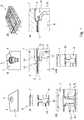
Figuren 1 und2 sind ein Verfahren zur Herstellung eines Plattenwärmetauschers sowie der dazugehörige Temperaturverlauf schematisch dargestellt. Zunächst werden eine Grundplatte 1 und eine Umformplatte 2 bereitgestellt. Dabei handelt es sich um Platten aus einer 3000er Aluminiumlegierung, beispielsweise einer Legierung mit der Bezeichnung, 3003, 3005, 3903 oder 3905. Die Dicke der Grundplatte 1 beträgt hier 1,3 Millimeter bis 2,0 Millimeter. Die Dicke der Umformplatte 2 beträgt 0,5 Millimeter bis 1,5 Millimeter. Die Umformplatte 2 ist mit einem Lotwerkstoff plattiert. In der Grundplatte 1 wird eine Anschlussöffnung 3 erzeugt. An der Anschlussöffnung 3 wird ein Anschlusselement 4 zusammen mit einem Lotring 5 angeordnet. - Die Grundplatte 1 und die Umformplatte 2 werden in Anlage gebracht und in ein vorgeheiztes Werkzeug 6 eingelegt. Das Werkzeug 6 ist dabei auf eine Temperatur von etwa 630°C vorgeheizt. Das Werkzeug 6 umfasst ein Oberwerkzeug 7 und eine Unterwerkzeug 8. In der Formfläche 9 des Oberwerkzeugs 7 sind Kavitäten 10 eingebracht, die den vorgesehenen Kanalstrukturen des herzustellenden Plattenwärmetauschers entsprechen. Das Unterwerkzeug 8 weist Aufnahmeöffnungen 11 für das Anschlusselement 4 auf. Zuführungskanäle 12 für ein Medium 14 zum innendrucktechnischen Umformen sind mit den Aufnahmeöffnungen 11 verbunden.
- Dann wird das Werkzeug 6 geschlossen. Dies entspricht dem Zeitpunkt t0 in dem Diagramm in
Figur 2 . Die in dem Werkzeug 6 zur Verfügung gestellte Wärme wird auf die Platten 1, 2 übertragen die somit aufgeheizt werden. - Zu einem Zeitpunkt t1 wird eine vorgesehene erste Temperatur T1 erreicht, bei der das innendrucktechnische Umformen gestartet wird. Der konkrete Zeitpunkt hängt von der Temperatur des Werkzeugs 6 sowie dem Material und der Dicke der Platten 1, 2 ab. Bei Platten 1, 2 aus Aluminium beträgt auf Grund seiner guten Wärmeleitungseigenschaften die Zeitspanne zwischen t0 und t1 nur wenige Sekunden. Die erste Temperatur T1 beträgt in diesem Ausführungsbeispiel 300°C bis 350°C.
- Für das innendrucktechnische Umformen wird ein Medium 14, vorzugsweise ein inertes Gas wie Stickstoff, unter Druck durch den Zuführungskanal 12, das Anschlusselement 4 und die Anschlussöffnung 3 zwischen die Platten 1, 2 geleitet. Dabei wird die Umformplatte 2 verformt, bis sie mit der Formfläche 9 des Oberwerkzeugs 7 in Anlage kommt. Das Werkzeug 6 beaufschlagt auch die Platten 1, 2 mit einem ersten Druck p1, um dem Innendruck des Mediums 14 entgegenzuwirken und um die entstehenden Kanalstrukturen abzudichten. Benachbart zu den Kavitäten 10 der Formflächen 9 sind Abdichtsicken 13 vorgesehen, die gewährleisten, dass der Umformvorgang ausschließlich im Bereich der Kavitäten 10 stattfindet. Somit werden eine hohe Maßhaltigkeit und Umformgenauigkeit gewährleistet.
- Wenn der Umformvorgang abgeschlossen ist (Zeitpunkt t2), werden die Platten 1, 2 weiter aufgeheizt. Bei etwa 560°C beginnt in diesem exemplarischen Verfahrensverlauf der Lotwerkstoff zu schmelzen. Zu einem Zeitpunkt t3 wird die zweite Temperatur T2 erreicht. Die zum Aufheizen benötigte Zeitspanne hängt wiederum von den verwendeten Materialien ab. Die zweite Temperatur T2 beträgt hier von 600°C bis 615 °C, bevorzugt etwa 610°C. Es beginnt das löttechnische Verbinden der Platten 1, 2 unter Beaufschlagung mit Wärme und einem zweiten Druck p2 durch das Werkzeug 6. Dabei werden die vollflächig in Anlage befindlichen Bereiche der Platten 1, 2 stoffschlüssig verbunden. Gleichzeitig wird das Anschlusselement 4 durch den Lotring 5 stoffschlüssig mit der Grundplatte 1 verbunden.
- Der zweite Druck p2 ist geringer als der erste Druck p1, um einem möglichen Anhaften der Aluminiumplatten 1, 2 an dem Werkzeug 6 entgegenzuwirken. Zu diesem Zweck weisen das Oberwerkzeug 7 und/oder das Unterwerkzeug 8 eine Federlagerung auf.
- Zu einem Zeitpunkt t4 ist das löttechnische Verbinden abgeschlossen. Danach werden die miteinander verbundenen Platten 1, 2 wieder bis auf Raumtemperatur abgekühlt (Zeitpunkt t6). Dazu wird der Plattenwärmetauscher 15 aus dem Werkzeug 6 entnommen und entweder in ein Kühlwerkzeug überführt oder in einem Kühlgestell abgelegt.
- Insbesondere kann das Medium für das innendrucktechnische Umformen zum Abkühlen oder zur Unterstützung des Abkühlprozesses verwendet werden. Bei der Verwendung von Stickstoff als inertem Medium ergibt sich der zusätzliche Vorteil, dass die Bildung einer Oxidschicht verhindert wird. Zudem erfolgt das Abkühlen etwas gleichmäßiger und reduziert eine Verformung der Platten, die durch innere Spannungen hervorgerufen werden können.
- Optional können währenddessen oder danach weitere Wärmebehandlungsschritte erfolgen.
- Zum Zeitpunkt t5 ist der Lotwerkstoff erstarrt. Die Zeitspanne zwischen t4 und t5 ist vorzugsweise sehr kurz und beträgt nur wenige Minuten oder gar Sekunden. Die kurze Abkühlzeit bis zur Loterstarrung führt dazu, dass in der Lotschicht eutektische Gefügestrukturen mit einer längsten Ausdehnung von weniger als 50 Mikrometern ausgebildet sind.
-
Figur 3 stellt zwei Schliffbilder gegenüber. In der oberen Abbildung ist eine Lotansammlung im Übergangsbereich zwischen den Kanalstrukturen und den in Anlage befindlichen Platten 1, 2 dargestellt, die in der Zeichenebene rechts der Abbildung zu finden wären. Diese Lotverbindung wurde in einem herkömmlichen Ofenlötprozess mit langen Abkühlzeiten erzeugt. Es sind eutektische Gefügestrukturen ausgebildet, die längsgestreckt oder nadelförmig sind und eine Längenausdehnung von 200 Mikrometern und mehr aufweisen. - Dem gegenüber ist in der unteren Abbildung eine Lotschicht gezeigt, die bei der Herstellung des erfindungsgemäßen Plattenwärmetauschers erzeugt worden ist. In den dunklen Bereichen sind die entsprechenden eutektischen Gefügestrukturen ausgebildet. Diese sind weitaus feinkörniger als in der oberen Abbildung mit Ausdehnungen kleiner als 50 Mikrometer. Das feinkörnige Gefüge führt dazu, dass die Lotverbindung deutlich stabiler und ermüdungsresistenter ist. Insbesondere im Bereich des Übergangs zwischen den Kanalstrukturen und den verlöteten Bereichen ist die wichtig, da dort im Betrieb hohe Belastungen auftreten, die zu Rissen und einem Auseinanderklaffen der beiden Platten 1, 2 führen können.
-
- 1 - Grundplatte
- 2 - Umformplatte
- 3 - Anschlussöffnung
- 4 - Anschlusselement
- 5 - Lotring
- 6 - Werkzeug
- 7 - Oberwerkzeug
- 8 - Unterwerkzeug
- 9 - Formfläche von 7
- 10 - Kavität
- 11 - Aufnahmeöffnung
- 12 - Zuführungskanal
- 13 - Abdichtsicke
- 14 - Medium
- 15 - Plattenwärmetauscher
- p1 - erster Druck
- p2 - zweiter Druck
- T1 - erste Temperatur
- T2 - zweite Temperatur
- t0 - Zeitpunkt
- t1 - Zeitpunkt
- t2 - Zeitpunkt
- t3 - Zeitpunkt
- t4 - Zeitpunkt
- t5 - Zeitpunkt
- t6 - Zeitpunkt
Claims (10)
- Plattenwärmetauscher (15) umfassend zwei Platten (1,2) aus einem metallischen Material, wobei Kanalstrukturen in zumindest einer Platte (1,2) ausgebildet sind und die Platten (1,2) abseits der Kanalstrukturen löttechnisch miteinander verbunden sind, dadurch gekennzeichnet, dass in der Lotschicht eutektische Gefügestrukturen mit einer längsten Ausdehnung von weniger als 50 Mikrometern ausgebildet sind.
- Plattenwärmetauscher (15) nach Anspruch 1, dadurch gekennzeichnet, dass die eutektischen Gefügestrukturen in Lotansammlungen im Übergangsbereich von den in Anlage befindlichen Platten (1, 2) zu den Kanalstrukturen ausgebildet sind.
- Plattenwärmetauscher (15) nach Anspruch 1 oder 2, dadurch gekennzeichnet, dass eine Platte als Grundplatte (1) und die andere Platte als Umformplatte (2) vorgesehen ist, wobei die Kanalstrukturen in der Umformplatte (2) erzeugt sind.
- Plattenwärmetauscher (15) nach einem der Ansprüche 1 bis 3, dadurch gekennzeichnet, dass die Platten (1, 2) aus einer Aluminiumlegierung, bevorzugt aus einer hochfesten Aluminiumlegierung, bestehen.
- Plattenwärmetauscher (15) nach einem der Ansprüche 1 bis 4, dadurch gekennzeichnet, dass in zumindest einer Platten (1, 2) eine Anschlussöffnung (3) vorgesehen ist.
- Plattenwärmetauscher (15) nach Anspruch 5, dadurch gekennzeichnet, dass an oder in der Anschlussöffnung (3) ein Anschlusselement (4) angeordnet ist.
- Plattenwärmetauscher (15) nach einem der Ansprüche 1 bis 6, dadurch gekennzeichnet, dass die Grundplatte (1) eine Dicke von 0,5 bis 5,0 Millimeter, bevorzugt 1,0 bis 2,0 Millimeter, aufweist und die Umformplatte (2) eine Dicke von 0,2 bis 2,0 Millimeter, bevorzugt 0,8 bis 1,0 Millimeter, aufweist.
- Plattenwärmetauscher (15) nach einem der Ansprüche 1 bis 7, dadurch gekennzeichnet, dass die Kanalstrukturen durch innendrucktechnische Umformung zumindest einer Platte (1, 2) ausgebildet sind.
- Plattenwärmetauscher (15) nach einem der Ansprüche 1 bis 8, dadurch gekennzeichnet, dass im Plattenwärmetauscher (15) steifigkeitserhöhende Sicken vorgesehen sind, die nicht in Fluidverbindung zu den Kanalstrukturen stehen.
- Plattenwärmetauscher (15) nach einem der Ansprüche 1 bis 9, dadurch gekennzeichnet, dass zumindest eine der Platten (1, 2) eine Streckgrenze Rp0,2 im Zugversuch von mehr als 100MPa, bevorzugt mehr als 140MPa, besonders bevorzugt mehr als 160MPa, aufweist.
Applications Claiming Priority (2)
| Application Number | Priority Date | Filing Date | Title |
|---|---|---|---|
| DE102019120862.9A DE102019120862A1 (de) | 2019-08-01 | 2019-08-01 | Verfahren zur Herstellung eines Plattenwärmetauschers sowie Plattenwärmetauscher |
| EP20186967.4A EP3771878B1 (de) | 2019-08-01 | 2020-07-21 | Verfahren zur herstellung eines plattenwärmetauschers |
Related Parent Applications (2)
| Application Number | Title | Priority Date | Filing Date |
|---|---|---|---|
| EP20186967.4A Division EP3771878B1 (de) | 2019-08-01 | 2020-07-21 | Verfahren zur herstellung eines plattenwärmetauschers |
| EP20186967.4A Division-Into EP3771878B1 (de) | 2019-08-01 | 2020-07-21 | Verfahren zur herstellung eines plattenwärmetauschers |
Publications (2)
| Publication Number | Publication Date |
|---|---|
| EP3839402A1 true EP3839402A1 (de) | 2021-06-23 |
| EP3839402B1 EP3839402B1 (de) | 2022-04-13 |
Family
ID=71738075
Family Applications (2)
| Application Number | Title | Priority Date | Filing Date |
|---|---|---|---|
| EP20186967.4A Active EP3771878B1 (de) | 2019-08-01 | 2020-07-21 | Verfahren zur herstellung eines plattenwärmetauschers |
| EP21156850.6A Active EP3839402B1 (de) | 2019-08-01 | 2020-07-21 | Plattenwärmetauscher |
Family Applications Before (1)
| Application Number | Title | Priority Date | Filing Date |
|---|---|---|---|
| EP20186967.4A Active EP3771878B1 (de) | 2019-08-01 | 2020-07-21 | Verfahren zur herstellung eines plattenwärmetauschers |
Country Status (6)
| Country | Link |
|---|---|
| US (2) | US11400532B2 (de) |
| EP (2) | EP3771878B1 (de) |
| CN (1) | CN112296616B (de) |
| DE (1) | DE102019120862A1 (de) |
| ES (2) | ES2953748T3 (de) |
| HU (1) | HUE059140T2 (de) |
Families Citing this family (3)
| Publication number | Priority date | Publication date | Assignee | Title |
|---|---|---|---|---|
| US12066259B2 (en) * | 2021-10-17 | 2024-08-20 | Jun He Technology Co., Ltd. | Heat exchanger |
| ES2988037T3 (es) | 2022-01-10 | 2024-11-19 | Benteler Automobiltechnik Gmbh | Procedimiento y herramienta de conformación en caliente para producir una placa intercambiadora de calor |
| JP2024039665A (ja) * | 2022-06-29 | 2024-03-25 | ヴァレオ システム テルミク | 熱交換器の製造方法 |
Citations (12)
| Publication number | Priority date | Publication date | Assignee | Title |
|---|---|---|---|---|
| DE4426097A1 (de) * | 1994-07-22 | 1996-01-25 | Kloeckner Stahl Gmbh | Verfahren zur Herstellung von Hohlkörperstrukturen aus Blechen |
| WO1996037335A1 (en) * | 1995-05-22 | 1996-11-28 | Alliedsignal Inc. | Nickel-chronium-based brazing alloys |
| WO1998037457A1 (de) * | 1997-02-20 | 1998-08-27 | Atotech Deutschland Gmbh | Chemische mikroreaktoren und verfahren zu deren herstellung |
| EP1195208A2 (de) * | 2000-10-07 | 2002-04-10 | DaimlerChrysler AG | Verfahren zum Herstellen lokal verstärkter Blechumformteile |
| WO2005011858A1 (de) * | 2003-07-31 | 2005-02-10 | Stockhausen Gmbh | Beschichteter katalysator-trägerkörper |
| WO2009126339A2 (en) * | 2008-01-14 | 2009-10-15 | Board Of Supervisors Of Louisiana State University And Agricultural And Mechanical College | Metal-based microchannel heat exchangers made by molding replication and assembly |
| WO2010132018A1 (en) * | 2009-05-14 | 2010-11-18 | Sapa Heat Transfer Ab | Aluminium brazing sheet with a high strength and excellent corrosion performance |
| DE102010051106A1 (de) | 2010-11-11 | 2012-05-16 | Audi Ag | Vorrichtung zum Kühlen eines Energiespeichermoduls eines Fahrzeugs |
| DE102011077154A1 (de) | 2011-05-25 | 2012-11-29 | J. Eberspächer GmbH & Co. KG | Verdampfer |
| DE102014219812A1 (de) | 2014-09-30 | 2016-03-31 | Robert Bosch Gmbh | Kühlplatte für einen elektrischen Energiespeicher |
| DE102016107946A1 (de) | 2016-04-28 | 2017-11-02 | Schuler Pressen Gmbh | Verfahren zum Fertigen eines hohlen Bauteils, Bauteil und Presse zum Fertigen eines hohlen Bauteils |
| DE102012009148B4 (de) | 2012-05-08 | 2018-09-20 | Fraunhofer-Gesellschaft zur Förderung der angewandten Forschung e.V. | Fahrzeug-Strukturbauteil und Fahrzeug mit diesem |
Family Cites Families (7)
| Publication number | Priority date | Publication date | Assignee | Title |
|---|---|---|---|---|
| FR2721041B1 (fr) | 1994-06-13 | 1997-10-10 | Pechiney Recherche | Tôle d'alliage aluminium-silicium destinée à la construction mécanique, aéronautique et spatiale. |
| US20020119079A1 (en) | 1999-12-10 | 2002-08-29 | Norbert Breuer | Chemical microreactor and microreactor made by process |
| EP2313728A1 (de) | 2008-06-13 | 2011-04-27 | Goodman Global, Inc. | Verfahren zur herstellung eines rohr- und rippenwärmetauschers mit reduziertem rohrdurchmesser und dadurch hergestellte optimierte rippe |
| CN101691961B (zh) | 2009-09-30 | 2011-05-25 | 重庆大学 | 不锈钢板式换热器加工成型方法 |
| BR112014017965B1 (pt) | 2012-01-27 | 2022-07-12 | Uacj Corporation | Material de liga de alumínio para barbatana de trocador de calor, método de sua fabricação e trocador de calor que utiliza o mencionado material de liga de alumínio |
| WO2014084424A1 (ko) | 2012-11-30 | 2014-06-05 | 인하대학교 산학협력단 | 고방열 고강도 알루미늄 합금 |
| JP7042023B2 (ja) * | 2014-12-11 | 2022-03-25 | 株式会社Uacj | ろう付方法 |
-
2019
- 2019-08-01 DE DE102019120862.9A patent/DE102019120862A1/de not_active Withdrawn
-
2020
- 2020-07-21 EP EP20186967.4A patent/EP3771878B1/de active Active
- 2020-07-21 ES ES20186967T patent/ES2953748T3/es active Active
- 2020-07-21 EP EP21156850.6A patent/EP3839402B1/de active Active
- 2020-07-21 ES ES21156850T patent/ES2920682T3/es active Active
- 2020-07-21 HU HUE21156850A patent/HUE059140T2/hu unknown
- 2020-07-31 CN CN202010755898.9A patent/CN112296616B/zh active Active
- 2020-07-31 US US16/944,887 patent/US11400532B2/en active Active
-
2021
- 2021-12-07 US US17/544,653 patent/US11633796B2/en active Active
Patent Citations (12)
| Publication number | Priority date | Publication date | Assignee | Title |
|---|---|---|---|---|
| DE4426097A1 (de) * | 1994-07-22 | 1996-01-25 | Kloeckner Stahl Gmbh | Verfahren zur Herstellung von Hohlkörperstrukturen aus Blechen |
| WO1996037335A1 (en) * | 1995-05-22 | 1996-11-28 | Alliedsignal Inc. | Nickel-chronium-based brazing alloys |
| WO1998037457A1 (de) * | 1997-02-20 | 1998-08-27 | Atotech Deutschland Gmbh | Chemische mikroreaktoren und verfahren zu deren herstellung |
| EP1195208A2 (de) * | 2000-10-07 | 2002-04-10 | DaimlerChrysler AG | Verfahren zum Herstellen lokal verstärkter Blechumformteile |
| WO2005011858A1 (de) * | 2003-07-31 | 2005-02-10 | Stockhausen Gmbh | Beschichteter katalysator-trägerkörper |
| WO2009126339A2 (en) * | 2008-01-14 | 2009-10-15 | Board Of Supervisors Of Louisiana State University And Agricultural And Mechanical College | Metal-based microchannel heat exchangers made by molding replication and assembly |
| WO2010132018A1 (en) * | 2009-05-14 | 2010-11-18 | Sapa Heat Transfer Ab | Aluminium brazing sheet with a high strength and excellent corrosion performance |
| DE102010051106A1 (de) | 2010-11-11 | 2012-05-16 | Audi Ag | Vorrichtung zum Kühlen eines Energiespeichermoduls eines Fahrzeugs |
| DE102011077154A1 (de) | 2011-05-25 | 2012-11-29 | J. Eberspächer GmbH & Co. KG | Verdampfer |
| DE102012009148B4 (de) | 2012-05-08 | 2018-09-20 | Fraunhofer-Gesellschaft zur Förderung der angewandten Forschung e.V. | Fahrzeug-Strukturbauteil und Fahrzeug mit diesem |
| DE102014219812A1 (de) | 2014-09-30 | 2016-03-31 | Robert Bosch Gmbh | Kühlplatte für einen elektrischen Energiespeicher |
| DE102016107946A1 (de) | 2016-04-28 | 2017-11-02 | Schuler Pressen Gmbh | Verfahren zum Fertigen eines hohlen Bauteils, Bauteil und Presse zum Fertigen eines hohlen Bauteils |
Also Published As
| Publication number | Publication date |
|---|---|
| US20210031288A1 (en) | 2021-02-04 |
| EP3771878A2 (de) | 2021-02-03 |
| ES2920682T3 (es) | 2022-08-08 |
| ES2953748T3 (es) | 2023-11-15 |
| DE102019120862A1 (de) | 2021-02-04 |
| US11400532B2 (en) | 2022-08-02 |
| CN112296616A (zh) | 2021-02-02 |
| US11633796B2 (en) | 2023-04-25 |
| EP3771878B1 (de) | 2023-07-19 |
| US20220088693A1 (en) | 2022-03-24 |
| EP3771878A3 (de) | 2021-04-14 |
| HUE059140T2 (hu) | 2022-10-28 |
| EP3839402B1 (de) | 2022-04-13 |
| CN112296616B (zh) | 2022-05-31 |
Similar Documents
| Publication | Publication Date | Title |
|---|---|---|
| EP2851138B1 (de) | Partiell gekühltes Warmformwerkzeug | |
| EP3839402B1 (de) | Plattenwärmetauscher | |
| DE112007001331T5 (de) | Verfahren und Vorrichtung zum Verbinden | |
| DE102009038896B4 (de) | Verfahren zur Herstellung eines aus einem ersten und zweiten Bauteil gefügten Strukturbauteils sowie Vorrichtung zur Durchführung des Verfahrens | |
| DE2757457C3 (de) | Verfahren zum flußmittellosen Hartlöten von Aluminiumbauteilen | |
| DE102009060388A1 (de) | Mehrstufiges direktes Formhärten | |
| DE102017117675A1 (de) | Verfahren zur Herstellung eines Kraftfahrzeugbauteils aus einer 6000er Aluminiumlegierung | |
| EP1658148B2 (de) | Verfahren zum umformen von blechen | |
| EP3456456A1 (de) | Verfahren zur herstellung von tailor welded blanks (twbs) | |
| DE102011051935A1 (de) | Verfahren zur Herstellung eines Wärmetauschers und Wärmetauscher | |
| DE102007040013B4 (de) | Werkzeug für das Warmumformen oder Presshärten eines Metallblechs sowie Verfahren zur Einstellung des Kühlverhaltens eines Werkzeugs | |
| DE102019009224A1 (de) | Plattenwärmetauscher | |
| DE102006020623B4 (de) | Verfahren zum Herstellen von Bauteilen aus tailored blanks | |
| DE102005038493B4 (de) | Verfahren zur Herstellung einer Fügeverbindung zwischen zwei Blechen | |
| DE102007018281A1 (de) | Werkzeug zum Innenhochdruckformen, sowie Verfahren zum Innenhochdruckformen | |
| DE102014221423A1 (de) | Verfahren zur Herstellung großer Warmumformwerkzeuge mittels eines generativen Fertigungsverfahrens | |
| AT527041B1 (de) | Verfahren zur Herstellung einer Kühlanordnung sowie Kühlanordnung für leistungselektronische Bauteile | |
| DE19852809A1 (de) | Verfahren und Vorrichtung zum thermisch unterstützten mechanischen Fügen | |
| DE102017001528A1 (de) | Formwerkzeug | |
| DE102021202737A1 (de) | Verfahren zum Verbinden eines wärmeerzeugenden Bauteils mit einer Kühlvorrichtung | |
| AT526330A4 (de) | Verfahren zur Herstellung einer Kühlvorrichtung | |
| EP3778056B1 (de) | Verfahren zur warmumformung von aluminiumblechen mittels reckziehens | |
| DE10359807B4 (de) | Mikrostruktur sowie Verfahren und Einrichtung zu deren Herstellung | |
| EP4209289A1 (de) | Verfahren und warmformwerkzeug zur herstellung einer wärmeübertragerplatte | |
| DE102020005115A1 (de) | Verfahren zum Herstellen einer Bauteilanordnung sowie Bauteilanordnung |
Legal Events
| Date | Code | Title | Description |
|---|---|---|---|
| PUAI | Public reference made under article 153(3) epc to a published international application that has entered the european phase |
Free format text: ORIGINAL CODE: 0009012 |
|
| STAA | Information on the status of an ep patent application or granted ep patent |
Free format text: STATUS: THE APPLICATION HAS BEEN PUBLISHED |
|
| AC | Divisional application: reference to earlier application |
Ref document number: 3771878 Country of ref document: EP Kind code of ref document: P |
|
| AK | Designated contracting states |
Kind code of ref document: A1 Designated state(s): AL AT BE BG CH CY CZ DE DK EE ES FI FR GB GR HR HU IE IS IT LI LT LU LV MC MK MT NL NO PL PT RO RS SE SI SK SM TR |
|
| STAA | Information on the status of an ep patent application or granted ep patent |
Free format text: STATUS: REQUEST FOR EXAMINATION WAS MADE |
|
| 17P | Request for examination filed |
Effective date: 20210712 |
|
| RBV | Designated contracting states (corrected) |
Designated state(s): AL AT BE BG CH CY CZ DE DK EE ES FI FR GB GR HR HU IE IS IT LI LT LU LV MC MK MT NL NO PL PT RO RS SE SI SK SM TR |
|
| GRAP | Despatch of communication of intention to grant a patent |
Free format text: ORIGINAL CODE: EPIDOSNIGR1 |
|
| STAA | Information on the status of an ep patent application or granted ep patent |
Free format text: STATUS: GRANT OF PATENT IS INTENDED |
|
| INTG | Intention to grant announced |
Effective date: 20211118 |
|
| GRAS | Grant fee paid |
Free format text: ORIGINAL CODE: EPIDOSNIGR3 |
|
| GRAA | (expected) grant |
Free format text: ORIGINAL CODE: 0009210 |
|
| STAA | Information on the status of an ep patent application or granted ep patent |
Free format text: STATUS: THE PATENT HAS BEEN GRANTED |
|
| AC | Divisional application: reference to earlier application |
Ref document number: 3771878 Country of ref document: EP Kind code of ref document: P |
|
| AK | Designated contracting states |
Kind code of ref document: B1 Designated state(s): AL AT BE BG CH CY CZ DE DK EE ES FI FR GB GR HR HU IE IS IT LI LT LU LV MC MK MT NL NO PL PT RO RS SE SI SK SM TR |
|
| REG | Reference to a national code |
Ref country code: GB Ref legal event code: FG4D Free format text: NOT ENGLISH |
|
| REG | Reference to a national code |
Ref country code: CH Ref legal event code: EP |
|
| REG | Reference to a national code |
Ref country code: DE Ref legal event code: R096 Ref document number: 502020000940 Country of ref document: DE |
|
| REG | Reference to a national code |
Ref country code: IE Ref legal event code: FG4D Free format text: LANGUAGE OF EP DOCUMENT: GERMAN |
|
| REG | Reference to a national code |
Ref country code: AT Ref legal event code: REF Ref document number: 1483714 Country of ref document: AT Kind code of ref document: T Effective date: 20220515 |
|
| REG | Reference to a national code |
Ref country code: ES Ref legal event code: FG2A Ref document number: 2920682 Country of ref document: ES Kind code of ref document: T3 Effective date: 20220808 |
|
| REG | Reference to a national code |
Ref country code: LT Ref legal event code: MG9D |
|
| REG | Reference to a national code |
Ref country code: NL Ref legal event code: MP Effective date: 20220413 |
|
| PG25 | Lapsed in a contracting state [announced via postgrant information from national office to epo] |
Ref country code: NL Free format text: LAPSE BECAUSE OF FAILURE TO SUBMIT A TRANSLATION OF THE DESCRIPTION OR TO PAY THE FEE WITHIN THE PRESCRIBED TIME-LIMIT Effective date: 20220413 |
|
| REG | Reference to a national code |
Ref country code: HU Ref legal event code: AG4A Ref document number: E059140 Country of ref document: HU |
|
| PG25 | Lapsed in a contracting state [announced via postgrant information from national office to epo] |
Ref country code: SE Free format text: LAPSE BECAUSE OF FAILURE TO SUBMIT A TRANSLATION OF THE DESCRIPTION OR TO PAY THE FEE WITHIN THE PRESCRIBED TIME-LIMIT Effective date: 20220413 Ref country code: PT Free format text: LAPSE BECAUSE OF FAILURE TO SUBMIT A TRANSLATION OF THE DESCRIPTION OR TO PAY THE FEE WITHIN THE PRESCRIBED TIME-LIMIT Effective date: 20220816 Ref country code: NO Free format text: LAPSE BECAUSE OF FAILURE TO SUBMIT A TRANSLATION OF THE DESCRIPTION OR TO PAY THE FEE WITHIN THE PRESCRIBED TIME-LIMIT Effective date: 20220713 Ref country code: LT Free format text: LAPSE BECAUSE OF FAILURE TO SUBMIT A TRANSLATION OF THE DESCRIPTION OR TO PAY THE FEE WITHIN THE PRESCRIBED TIME-LIMIT Effective date: 20220413 Ref country code: HR Free format text: LAPSE BECAUSE OF FAILURE TO SUBMIT A TRANSLATION OF THE DESCRIPTION OR TO PAY THE FEE WITHIN THE PRESCRIBED TIME-LIMIT Effective date: 20220413 Ref country code: GR Free format text: LAPSE BECAUSE OF FAILURE TO SUBMIT A TRANSLATION OF THE DESCRIPTION OR TO PAY THE FEE WITHIN THE PRESCRIBED TIME-LIMIT Effective date: 20220714 Ref country code: FI Free format text: LAPSE BECAUSE OF FAILURE TO SUBMIT A TRANSLATION OF THE DESCRIPTION OR TO PAY THE FEE WITHIN THE PRESCRIBED TIME-LIMIT Effective date: 20220413 Ref country code: BG Free format text: LAPSE BECAUSE OF FAILURE TO SUBMIT A TRANSLATION OF THE DESCRIPTION OR TO PAY THE FEE WITHIN THE PRESCRIBED TIME-LIMIT Effective date: 20220713 |
|
| PG25 | Lapsed in a contracting state [announced via postgrant information from national office to epo] |
Ref country code: RS Free format text: LAPSE BECAUSE OF FAILURE TO SUBMIT A TRANSLATION OF THE DESCRIPTION OR TO PAY THE FEE WITHIN THE PRESCRIBED TIME-LIMIT Effective date: 20220413 Ref country code: PL Free format text: LAPSE BECAUSE OF FAILURE TO SUBMIT A TRANSLATION OF THE DESCRIPTION OR TO PAY THE FEE WITHIN THE PRESCRIBED TIME-LIMIT Effective date: 20220413 Ref country code: LV Free format text: LAPSE BECAUSE OF FAILURE TO SUBMIT A TRANSLATION OF THE DESCRIPTION OR TO PAY THE FEE WITHIN THE PRESCRIBED TIME-LIMIT Effective date: 20220413 Ref country code: IS Free format text: LAPSE BECAUSE OF FAILURE TO SUBMIT A TRANSLATION OF THE DESCRIPTION OR TO PAY THE FEE WITHIN THE PRESCRIBED TIME-LIMIT Effective date: 20220813 |
|
| REG | Reference to a national code |
Ref country code: DE Ref legal event code: R097 Ref document number: 502020000940 Country of ref document: DE |
|
| PG25 | Lapsed in a contracting state [announced via postgrant information from national office to epo] |
Ref country code: SM Free format text: LAPSE BECAUSE OF FAILURE TO SUBMIT A TRANSLATION OF THE DESCRIPTION OR TO PAY THE FEE WITHIN THE PRESCRIBED TIME-LIMIT Effective date: 20220413 Ref country code: SK Free format text: LAPSE BECAUSE OF FAILURE TO SUBMIT A TRANSLATION OF THE DESCRIPTION OR TO PAY THE FEE WITHIN THE PRESCRIBED TIME-LIMIT Effective date: 20220413 Ref country code: RO Free format text: LAPSE BECAUSE OF FAILURE TO SUBMIT A TRANSLATION OF THE DESCRIPTION OR TO PAY THE FEE WITHIN THE PRESCRIBED TIME-LIMIT Effective date: 20220413 Ref country code: EE Free format text: LAPSE BECAUSE OF FAILURE TO SUBMIT A TRANSLATION OF THE DESCRIPTION OR TO PAY THE FEE WITHIN THE PRESCRIBED TIME-LIMIT Effective date: 20220413 Ref country code: DK Free format text: LAPSE BECAUSE OF FAILURE TO SUBMIT A TRANSLATION OF THE DESCRIPTION OR TO PAY THE FEE WITHIN THE PRESCRIBED TIME-LIMIT Effective date: 20220413 |
|
| PLBE | No opposition filed within time limit |
Free format text: ORIGINAL CODE: 0009261 |
|
| STAA | Information on the status of an ep patent application or granted ep patent |
Free format text: STATUS: NO OPPOSITION FILED WITHIN TIME LIMIT |
|
| PG25 | Lapsed in a contracting state [announced via postgrant information from national office to epo] |
Ref country code: MC Free format text: LAPSE BECAUSE OF FAILURE TO SUBMIT A TRANSLATION OF THE DESCRIPTION OR TO PAY THE FEE WITHIN THE PRESCRIBED TIME-LIMIT Effective date: 20220413 |
|
| 26N | No opposition filed |
Effective date: 20230116 |
|
| REG | Reference to a national code |
Ref country code: BE Ref legal event code: MM Effective date: 20220731 |
|
| PG25 | Lapsed in a contracting state [announced via postgrant information from national office to epo] |
Ref country code: AL Free format text: LAPSE BECAUSE OF FAILURE TO SUBMIT A TRANSLATION OF THE DESCRIPTION OR TO PAY THE FEE WITHIN THE PRESCRIBED TIME-LIMIT Effective date: 20220413 |
|
| PG25 | Lapsed in a contracting state [announced via postgrant information from national office to epo] |
Ref country code: LU Free format text: LAPSE BECAUSE OF NON-PAYMENT OF DUE FEES Effective date: 20220721 Ref country code: FR Free format text: LAPSE BECAUSE OF NON-PAYMENT OF DUE FEES Effective date: 20220731 |
|
| PG25 | Lapsed in a contracting state [announced via postgrant information from national office to epo] |
Ref country code: SI Free format text: LAPSE BECAUSE OF FAILURE TO SUBMIT A TRANSLATION OF THE DESCRIPTION OR TO PAY THE FEE WITHIN THE PRESCRIBED TIME-LIMIT Effective date: 20220413 Ref country code: BE Free format text: LAPSE BECAUSE OF NON-PAYMENT OF DUE FEES Effective date: 20220731 |
|
| PG25 | Lapsed in a contracting state [announced via postgrant information from national office to epo] |
Ref country code: IE Free format text: LAPSE BECAUSE OF NON-PAYMENT OF DUE FEES Effective date: 20220721 |
|
| PG25 | Lapsed in a contracting state [announced via postgrant information from national office to epo] |
Ref country code: IT Free format text: LAPSE BECAUSE OF FAILURE TO SUBMIT A TRANSLATION OF THE DESCRIPTION OR TO PAY THE FEE WITHIN THE PRESCRIBED TIME-LIMIT Effective date: 20220413 |
|
| REG | Reference to a national code |
Ref country code: CH Ref legal event code: PL |
|
| PG25 | Lapsed in a contracting state [announced via postgrant information from national office to epo] |
Ref country code: MK Free format text: LAPSE BECAUSE OF FAILURE TO SUBMIT A TRANSLATION OF THE DESCRIPTION OR TO PAY THE FEE WITHIN THE PRESCRIBED TIME-LIMIT Effective date: 20220413 Ref country code: CY Free format text: LAPSE BECAUSE OF FAILURE TO SUBMIT A TRANSLATION OF THE DESCRIPTION OR TO PAY THE FEE WITHIN THE PRESCRIBED TIME-LIMIT Effective date: 20220413 Ref country code: CH Free format text: LAPSE BECAUSE OF NON-PAYMENT OF DUE FEES Effective date: 20230731 |
|
| PG25 | Lapsed in a contracting state [announced via postgrant information from national office to epo] |
Ref country code: TR Free format text: LAPSE BECAUSE OF FAILURE TO SUBMIT A TRANSLATION OF THE DESCRIPTION OR TO PAY THE FEE WITHIN THE PRESCRIBED TIME-LIMIT Effective date: 20220413 |
|
| PG25 | Lapsed in a contracting state [announced via postgrant information from national office to epo] |
Ref country code: MT Free format text: LAPSE BECAUSE OF FAILURE TO SUBMIT A TRANSLATION OF THE DESCRIPTION OR TO PAY THE FEE WITHIN THE PRESCRIBED TIME-LIMIT Effective date: 20220413 |
|
| PG25 | Lapsed in a contracting state [announced via postgrant information from national office to epo] |
Ref country code: BG Free format text: LAPSE BECAUSE OF FAILURE TO SUBMIT A TRANSLATION OF THE DESCRIPTION OR TO PAY THE FEE WITHIN THE PRESCRIBED TIME-LIMIT Effective date: 20220413 |
|
| PG25 | Lapsed in a contracting state [announced via postgrant information from national office to epo] |
Ref country code: BG Free format text: LAPSE BECAUSE OF FAILURE TO SUBMIT A TRANSLATION OF THE DESCRIPTION OR TO PAY THE FEE WITHIN THE PRESCRIBED TIME-LIMIT Effective date: 20220413 |
|
| GBPC | Gb: european patent ceased through non-payment of renewal fee |
Effective date: 20240721 |
|
| PG25 | Lapsed in a contracting state [announced via postgrant information from national office to epo] |
Ref country code: GB Free format text: LAPSE BECAUSE OF NON-PAYMENT OF DUE FEES Effective date: 20240721 |
|
| PGFP | Annual fee paid to national office [announced via postgrant information from national office to epo] |
Ref country code: HU Payment date: 20250723 Year of fee payment: 6 |
|
| PGFP | Annual fee paid to national office [announced via postgrant information from national office to epo] |
Ref country code: ES Payment date: 20250827 Year of fee payment: 6 |
|
| PGFP | Annual fee paid to national office [announced via postgrant information from national office to epo] |
Ref country code: DE Payment date: 20250729 Year of fee payment: 6 |
|
| PGFP | Annual fee paid to national office [announced via postgrant information from national office to epo] |
Ref country code: AT Payment date: 20251020 Year of fee payment: 5 |
|
| PGFP | Annual fee paid to national office [announced via postgrant information from national office to epo] |
Ref country code: CZ Payment date: 20250715 Year of fee payment: 6 |