EP3838823A1 - Yarn storage container and yarn storage system - Google Patents
Yarn storage container and yarn storage system Download PDFInfo
- Publication number
- EP3838823A1 EP3838823A1 EP20154821.1A EP20154821A EP3838823A1 EP 3838823 A1 EP3838823 A1 EP 3838823A1 EP 20154821 A EP20154821 A EP 20154821A EP 3838823 A1 EP3838823 A1 EP 3838823A1
- Authority
- EP
- European Patent Office
- Prior art keywords
- yarn
- tubular
- container
- axial
- extremity
- Prior art date
- Legal status (The legal status is an assumption and is not a legal conclusion. Google has not performed a legal analysis and makes no representation as to the accuracy of the status listed.)
- Granted
Links
Images



Classifications
-
- B—PERFORMING OPERATIONS; TRANSPORTING
- B65—CONVEYING; PACKING; STORING; HANDLING THIN OR FILAMENTARY MATERIAL
- B65H—HANDLING THIN OR FILAMENTARY MATERIAL, e.g. SHEETS, WEBS, CABLES
- B65H49/00—Unwinding or paying-out filamentary material; Supporting, storing or transporting packages from which filamentary material is to be withdrawn or paid-out
- B65H49/02—Methods or apparatus in which packages do not rotate
- B65H49/04—Package-supporting devices
- B65H49/14—Package-supporting devices for several operative packages
- B65H49/16—Stands or frameworks
-
- B—PERFORMING OPERATIONS; TRANSPORTING
- B65—CONVEYING; PACKING; STORING; HANDLING THIN OR FILAMENTARY MATERIAL
- B65H—HANDLING THIN OR FILAMENTARY MATERIAL, e.g. SHEETS, WEBS, CABLES
- B65H61/00—Applications of devices for metering predetermined lengths of running material
-
- B—PERFORMING OPERATIONS; TRANSPORTING
- B65—CONVEYING; PACKING; STORING; HANDLING THIN OR FILAMENTARY MATERIAL
- B65H—HANDLING THIN OR FILAMENTARY MATERIAL, e.g. SHEETS, WEBS, CABLES
- B65H67/00—Replacing or removing cores, receptacles, or completed packages at paying-out, winding, or depositing stations
- B65H67/04—Arrangements for removing completed take-up packages and or replacing by cores, formers, or empty receptacles at winding or depositing stations; Transferring material between adjacent full and empty take-up elements
- B65H67/0428—Arrangements for removing completed take-up packages and or replacing by cores, formers, or empty receptacles at winding or depositing stations; Transferring material between adjacent full and empty take-up elements for cans, boxes and other receptacles
-
- B—PERFORMING OPERATIONS; TRANSPORTING
- B65—CONVEYING; PACKING; STORING; HANDLING THIN OR FILAMENTARY MATERIAL
- B65H—HANDLING THIN OR FILAMENTARY MATERIAL, e.g. SHEETS, WEBS, CABLES
- B65H67/00—Replacing or removing cores, receptacles, or completed packages at paying-out, winding, or depositing stations
- B65H67/06—Supplying cores, receptacles, or packages to, or transporting from, winding or depositing stations
-
- B—PERFORMING OPERATIONS; TRANSPORTING
- B65—CONVEYING; PACKING; STORING; HANDLING THIN OR FILAMENTARY MATERIAL
- B65H—HANDLING THIN OR FILAMENTARY MATERIAL, e.g. SHEETS, WEBS, CABLES
- B65H75/00—Storing webs, tapes, or filamentary material, e.g. on reels
- B65H75/02—Cores, formers, supports, or holders for coiled, wound, or folded material, e.g. reels, spindles, bobbins, cop tubes, cans, mandrels or chucks
- B65H75/04—Kinds or types
- B65H75/16—Cans or receptacles, e.g. sliver cans
-
- B—PERFORMING OPERATIONS; TRANSPORTING
- B65—CONVEYING; PACKING; STORING; HANDLING THIN OR FILAMENTARY MATERIAL
- B65H—HANDLING THIN OR FILAMENTARY MATERIAL, e.g. SHEETS, WEBS, CABLES
- B65H75/00—Storing webs, tapes, or filamentary material, e.g. on reels
- B65H75/02—Cores, formers, supports, or holders for coiled, wound, or folded material, e.g. reels, spindles, bobbins, cop tubes, cans, mandrels or chucks
- B65H75/18—Constructional details
- B65H75/182—Identification means
-
- D—TEXTILES; PAPER
- D02—YARNS; MECHANICAL FINISHING OF YARNS OR ROPES; WARPING OR BEAMING
- D02H—WARPING, BEAMING OR LEASING
- D02H1/00—Creels, i.e. apparatus for supplying a multiplicity of individual threads
-
- D—TEXTILES; PAPER
- D03—WEAVING
- D03D—WOVEN FABRICS; METHODS OF WEAVING; LOOMS
- D03D39/00—Pile-fabric looms
- D03D39/02—Axminster looms, i.e. wherein pile tufts are inserted during weaving
-
- D—TEXTILES; PAPER
- D05—SEWING; EMBROIDERING; TUFTING
- D05C—EMBROIDERING; TUFTING
- D05C13/00—Auxiliary devices incorporated in embroidering machines, not otherwise provided for; Ancillary apparatus for use with embroidering machines
- D05C13/02—Counting, measuring, indicating, warning, or safety devices
-
- D—TEXTILES; PAPER
- D05—SEWING; EMBROIDERING; TUFTING
- D05C—EMBROIDERING; TUFTING
- D05C15/00—Making pile fabrics or articles having similar surface features by inserting loops into a base material
- D05C15/04—Tufting
- D05C15/08—Tufting machines
- D05C15/16—Arrangements or devices for manipulating threads
- D05C15/18—Thread feeding or tensioning arrangements
-
- B—PERFORMING OPERATIONS; TRANSPORTING
- B65—CONVEYING; PACKING; STORING; HANDLING THIN OR FILAMENTARY MATERIAL
- B65H—HANDLING THIN OR FILAMENTARY MATERIAL, e.g. SHEETS, WEBS, CABLES
- B65H2301/00—Handling processes for sheets or webs
- B65H2301/50—Auxiliary process performed during handling process
- B65H2301/51—Modifying a characteristic of handled material
- B65H2301/515—Cutting handled material
-
- B—PERFORMING OPERATIONS; TRANSPORTING
- B65—CONVEYING; PACKING; STORING; HANDLING THIN OR FILAMENTARY MATERIAL
- B65H—HANDLING THIN OR FILAMENTARY MATERIAL, e.g. SHEETS, WEBS, CABLES
- B65H2511/00—Dimensions; Position; Numbers; Identification; Occurrences
- B65H2511/10—Size; Dimensions
- B65H2511/11—Length
-
- B—PERFORMING OPERATIONS; TRANSPORTING
- B65—CONVEYING; PACKING; STORING; HANDLING THIN OR FILAMENTARY MATERIAL
- B65H—HANDLING THIN OR FILAMENTARY MATERIAL, e.g. SHEETS, WEBS, CABLES
- B65H2701/00—Handled material; Storage means
- B65H2701/30—Handled filamentary material
- B65H2701/31—Textiles threads or artificial strands of filaments
Definitions
- the present invention relates to yarn storage containers and yarn storage systems, in particular to yarn storage systems for plurality of yarns, such as yarn storage systems for yarns used as pile yarn in tufting processes.
- Tufting machines are known in the art. A large number of yarns, even up to or more than 1000 yarns, are tufted simultaneously into a primary backing to provide a greige product. For each yarn tufted, a yarn cone is held in a rack of yarns.
- a yarn storage container and an yarn storage system are provided.
- a yarn storage container for storing a yarn
- said storage container comprising a tubular container, having an axial length, a tubular wall and a first and second axial extremity, the first axial extremity of said tubular container having an opening for receiving an end of a yarn, said second axial extremity of said tubular container being air-permeably closed, said tubular wall is air permeable by means of a plurality of openings present along the axial length of said tubular container.
- the yarn storage container if fit for storing non wound yarn, i.e. yarn in non - would form.
- the tubular wall of the tubular container is air permeable and allows air passing in radial direction, in particularly from the inner side of the tubular container to the outer side of the tubular container.
- the tubular container hence has a perforated tubular wall.
- Each tubular container is fit for holding one yarn in non-wound form or appearance, having a length at least double of the axial length of the tubular container.
- Yarns which are non-wound are yarns which are not wound or coiled on a spool or bobbin or alike. The yarn is laid down freely and unguided within the void inside the tubular container.
- the second axial extremity of said container may be provided with an air permeable closing cap, such as e.g. a perforated cap from polymer or metal, which fits in or over the axial extremity of the tubular container.
- an air permeable closing cap such as e.g. a perforated cap from polymer or metal, which fits in or over the axial extremity of the tubular container.
- the second axial extremity of the tubular container is closed with a grid, e.g. a metal or polymer grid which is attached to the axial extremity.
- the open area of this air permeable closing cap may be in the range of 30 to 90 % of the total surface of the cap, such as e.g. in the range of 40 to 80%, more preferred n the rang of 45 to 75%.
- a yarn storage system comprises a plurality of yarn storage containers according to the first aspect of the invention.
- the working principle of the yarn storage system according to the invention is based upon the fact that such tubular containers can be filed with yarn by blowing yarn into the tube, e.g. by means of compressed fluid, such as air, via the opening at the first axial extremity of each of the tubular containers.
- the yarn end blown into the tubular container will be blown against the closure of the second axial extremity, and additional yarn length will gradually fill up the tubular container as the yarn is laid freely in the volume of the tubular container.
- the fluid blown in escapes the inner void of the tubular container via the air permeable closure of the second extremity, and/or the openings in the tubular wall.
- the yarns stuffs and fills the tubular container at least partially.
- the yarn storage system may be moved to the apparatus which is to consume the yarns and convert it into the required textile product.
- the yarns may be used by a tufting machine as pile yarn. During consumption of the yarns, the yarns may be gently dragged out of the tubular containers via the opening of the first axial extremity, hence in opposite direction as it was blown in.
- the yarn taken out of the container will show very little to no variation on tension, which facilitates the tension control of the yarn during conversion into a textile fabric.
- the apparatus which is to consume the yarns and convert it into the required textile product may e.g. be a tufting machine, a weaving loom, a warp or weft knitting loom, a sewing or embroidering machine and alike.
- the opening of the first axial extremity of said container for receiving an end of said non-wound yarn may be provided by leaving the first axial extremity of said container uncovered, hence open.
- the tubular container has a perforated tubular wall, i.e. a wall with openings.
- the openings may have any suitable shape, e.g. circular; polygonal shaped such as triangular, square, rectangular, diamond shaped, pentagonal, hexagonal and alike, optionally all of these polygonal shapes having rounded corners; capsule shaped (i.e. rectangular but terminated with half a circle at the short side of the rectangle); dog bone shaped; elliptic; or alike.
- the perforations may have a rim free of burrs. The inner rim of the perforations is preferably flush with the inner surface of the tubular container.
- the openings in the perforated tubular wall may be circular or rectangular, the latter optionally terminated with half a circle at the short side of the rectangle or having rounded corners.
- the rectangular opening optionally terminated with half a circle at the short side of the rectangle (also referred to as capsule-shaped) or having rounded corners, may have its long side parallel or perpendicular to the axial length of the tubular container.
- the openings define a total sum of open area along the tubular wall of the tubular container, hereinafter referred to as "open area".
- the average open area per surface unit of inner tubular wall may be in the range of 0.1 to 2.5%, more preferred in the range of 0.25 to 1%.
- Each opening preferably has a surface area in the range of 0.003 to 0.196 inch 2 , such as in the range of 0.008 to 0.05 inch 2 .
- the openings may be distributed along the tubular wall according to a geometrical pattern.
- the amount of open area per surface unit of inner tubular wall adjacent the first axial extremity may be smaller than the amount of open area per surface unit of inner tubular wall adjacent the second axial extremity.
- the amount of open area per surface unit of inner tubular wall may increase gradually from the first axial extremity to the second axil extremity.
- the amount of open area per surface unit of inner tubular wall may increase stepwise from the first axial extremity to the second axil extremity.
- the amount of open area per surface unit of inner tubular wall may increase stepwise (with at least one step) or gradually along the axial length of the tubular container from the first axial extremity to the second axial extremity. Possibly the amount of open area increases stepwise from the first axial extremity to the second axial extremity. As such different sections along the axial length of the tubular wall of the tubular container are defined.
- the open area per surface unit of tubular wall near the first axial extremity of the tubular container is in the range of 0.1 to 2.5%, more preferred in the range of 0.1 to 1% such as in the range of 0.1 to 0.5%.
- the open area per surface of tubular wall near the second axial extremity of the tubular container is in the range of 0.1 to 2.5%, more preferred in the range of 0.5 to 2.5% such as in the range of 0.5 to 1.5%.
- the open area may be varied over the surface of the tubular container by varying the number of openings per surface unit, by varying the shape of the openings, by varying the dimensions of the openings or by any combination of these measures.
- the inner tubular wall may comprise at least two sections, the amount of open area per surface unit of inner tubular wall in the section adjacent the first axial extremity is less than the amount of open area per surface unit of inner tubular wall in the section adjacent the second axil extremity.
- the tubular wall has two sections, i.e. with length Le1 and Le2, each located adjacent to one of the extremities.
- the lengths Le1 and Le2 together is the axial length of the tubular container.
- the length of the section adjacent the first axial extremity may have a length Le1 being 50 to 85% of the total axial length of the container.
- the length of the section adjacent the second axial extremity may have a length Le2 being 15 to 50% of the total axial length of the container.
- Le1 is about 75% of the total axial length of the container, Le2 being about 25% of the axial length of the container.
- the open area expressed as % of the surface area of inner tubular wall of the section adjacent the first axial extremity may be in the range of 0.1 to 2.5%, more preferred in the range of in the range of 0.1 to 1%, such as in the range of 0.1 to 0.5%.
- the open areas expressed as % of the surface area of inner tubular wall of the section adjacent the second axial extremity may be in the range of0.1 to 2.5%, more preferred in the range of 0.5 to 2.5% such as in the range of 0.5 to 1.5%.
- the openings may be distributed over the tubular wall according to rows of openings parallel between themselves, and aligned in axial direction, i.e. parallel to the axis of the tubular container.
- the openings may be equidistant within the row within each section.
- the distances between adjacent openings in a row may vary, e.g. decrease, in case the tubular wall has a varying, e.g. increasing, amount of open area per surface unit of tubular wall.
- the number of rows of openings may be constant along the axis of the tubular container or may vary between sections.
- the number of rows of openings may vary, e.g. increase, in case the tubular wall has a varying, e.g. increasing, amount of open area per surface unit of tubular wall for a given section. Or a combination of both these measures may be provided to provide varying open areas along the axial length of the tubular container.
- the first axial extremity of said tubular container may comprise a lid substantially closing said first axial extremity, said lid is provided with an hole for providing said opening for receiving an end of the non-wound yarn.
- the first axial extremity of said container may be provided with a lid, such as e.g. a lid from polymer or metal, which fits in and/or over the axial extremity of the tubular container.
- the lid may be e.g. a plug or a cap.
- the lid may be removably attached to the first axial extremity. It may be attached by clips or clamps, or just may fit in and/or over the tubular containers first axial extremity, where it fits and stays in place due to friction forces.
- the first axial extremity of said tubular container may comprise a grommet for receiving said end of said non-would yarn, said grommet being mechanically coupled to the first axial extremity of said tubular container.
- the grommet may fit into the hole of a lid substantially closing the first axial extremity.
- the grommet may be part of said lid, thereby providing the opening to the lid.
- the grommet may be a tube, typically of relative short length, such as 0.5 to 2 inches.
- the inner diameter of the tube opening may vary, such as between 0.25 and 2 inches, such as between 0.5 and 1 inches.
- the grommet may be electrically conductive.
- the grommet may be made from metal, such as iron, steel, copper, aluminum, bronze, messing, or any alternative metal alloy, or may be made from electrically conductive polymers, like carbon fiber or carbon powder filled polymer, such as carbon powder filled polypropylene, polyethylene, polyamide , polyvinylchloride or alike. In the alternative, the grommet may be porcelain.
- the lid may comprise one or a plurality of small openings along the contact zone where said lid contacts said first axial extremity.
- the openings may be small perforations, holes, slits and alike. Via these small openings a laminar air stream may be provided by gently blowing or sucking air through the small openings into the inner volume of the tubular container.
- the yarn storage container according the first aspect of the invention may comprise means for providing a laminar air stream in axial direction from the first axial extremity to the second axial extremity along the walls of the tubular container. This in fact provides a second, independent aspect of the present invention.
- the first axial extremity of said tubular container may comprise a brush for contacting said end of said yarn.
- the brush may be fitting into a hole provided in a lid which substantially closes the first axial extremity. Possibly the bristles of the brush close said opening.
- the bristles contacting the non-wound yarn in or passing through the opening is provided with a minimum of tension when the yarn is drawn out of the container.
- the brush may be a straight brush with bristles all being substantially parallel, or a circular brush with bristles oriented towards a central point.
- the bristles may overlap at the central point, but preferably leave a central opening, e.g. an opening of about 1 ⁇ 4" to 1", such as about %".
- the bristles may be electrically conductive and may be grounded to reduce the static loading of the yarn passing the opening.
- the storage container may comprise a grounding system for grounding the electrically conductive brush, grommet or tube.
- the container may comprise means for providing a laminar air stream in axial direction from the first axial extremity to the second axial extremity at least along the walls of the tubular container.
- the container may comprise means to create a sub-atmospheric pressure in the tubular container via the second axial extremity.
- sub-atmospheric pressure is meant a pressure being less than the ambient pressure. Causing such sub-atmospheric pressure via the second axial extremity, will help the yarn end, and the length of yarn blown into the tubular container, to move more easily and completely up to the second axial extremity. It may also help to increase the amount of yarn that can be introduced in to the tubular container because it may compress the inserted yarn in a direction towards the second axial extremity.
- This means to create sub-atmospheric pressure in combination with lids comprising one or a plurality of small openings along the contact zone where the lid contacts the first axial extremity may be part of, or may be sufficient to provide a means to create a laminar stream along the inner wall of the tubular container.
- the tubular container may have, in radial cross section, a circular, oval, square or rectangular cross section profile.
- the surface of a radial cross section of the tubular container may be between 0.75 and 13 inch 2 . More preferred, the surface of a radial cross section of the tubular container may be between 1.5 and 13 inch 2 , such as between 2 and 13 inch 2 .
- the tubular container may eb provided from steel, aluminum, cardboard or polymer, preferably a polymer chosen from the group consisting of polypropylene, polyethylene, polyamide, polystyrene and polyvinylchloride.
- the tubular container may be provided from any suitable material, preferably from metal, like aluminum, or polymer, preferably polyvinylchloride (PVC), polyethylene (PE), polypropylene (PP) or polystyrene (PS).
- PVC polyvinylchloride
- PE polyethylene
- PP polypropylene
- PS polystyrene
- the tubular wall is preferably transparent, allowing visual inspection of the yarn stored in the container.
- the tubular containers may have a tubular wall with a thickness which may be between 0.042 inch and 0.1 inch, when the tubular containers are metal or metallic containers.
- the tubular containers may have a tubular wall with a thickness which may be between 0.0625 and 0.25 inch when the tubular containers are cardboard or polymeric containers.
- the tubular container is a cardboard or polymeric tubular container, the inner wall of said tubular container being made electrically conductive.
- the electrical conductivity of the inner wall of the tubular container may be obtained by providing e.g. electrically conductive coating along the whole inner wall,. Alternatively, coating strips in axial direction or a spiraling strip along the length of the tubular container, made out of electroconductive material may be provided. Such electroconductive coating material may e.g. be silver, gold, aluminum or similar metal or metallic coatings.
- said system may comprise a grounding system for grounding electrically conductive tubular containers or the inner the electrically conductive inner wall of the tubular containers.
- This grounding system may be the same grounding system for grounding the electrically conductive grommets.
- the axial length of the tubular container may be between 15 and 110 inch. More preferred, the axial length of the tubular containers may be between 20 and 100 inch, such as between 24 and 96 inch.
- a yarn storage system comprising at least two yarn storage containers according to the first aspect of the invention.
- all tubular containers may have identical dimensions.
- the tubular containers may be organized in a rack.
- One rack may comprise 16 to 1024 tubular containers, more preferred 36 to 1000 containers, which may be organized in a matrix setting.
- the matrix may comprise 4 to 32 rows and 4 to 32 columns, more preferred 6 to 30 rows and 6 to 30 columns.
- the racks may be provided with a transporting system, rendering the yarn storage system movable.
- the rack may be provided with a plurality of wheels.
- the first axial extremities of all tubular containers may be coplanar.
- all tubular containers are coplanar as preferably all tubular containers are of equal length, and preferably are identical.
- the tubular containers may be oriented in a vertical position. According to some embodiments, the tubular containers may be oriented in a horizontal position.
- Each tubular container may be provided with at least one yarn detector, e.g. an electronical, mechanical or optical yarn detector, detecting the presence of a yarn at the opening of the first axial extremity of said containers.
- the yarn detectors may be part of a yarn detecting system, further equipped with a processing unit to receive signals of said yarn presence detectors indicating the presence or non-presence of yarns, and a signal generating means to generate a signal when at least one yarn detector fails to detect a yarn.
- the yarn storage system cooperates with machinery consuming yarn, e.g. a tufting machine, this machine may use the signal of said yarn detecting system to interrupt its yarn consumption when one or more tubular containers fail to have a yarn present, e.g. when it ran out of yarn stored in said tubular container.
- the yarn storage system further may comprise a yarn end holding means comprising a number of apertures or slots, said number of apertures or slots being identical or more that the number of tubular containers of the yarn storage system, each aperture or slot being fit to receive one yarn end from one of the tubular containers.
- the apertures or slots may all be adjacent one next to the other in a row, or may be organized in two or more rows, optionally in zig-zag setup.
- Each slot or aperture may be provided with a ceramic tube to prevent the passing yarn to wear out the aperture or slot.
- the yarn end holding means typically may be provided as a beam, i.e. rectangular, balk-like piece of metal or plastic in which the apertures or slits are provided. Most preferably the yarn end holding means has a comb-like structure
- a yarn storage system is used to supply textile machinery with yarn.
- a yarn storage system for providing yarn to a textile machine, such as to provide pile yarn to a tufting machine.
- the yarn storage system may be used to store bulked continuous filament yarns, such as used by tufting machines to provide pile yarn of the tufted greige, hence of the tufted carpet.
- the yarn storage system may as well be used to provide yarns to any other textile producing equipment, such as warp knitting machines, as warp yarn for weaving looms, such as carpet weaving looms, and alike.
- a method to store yarns in provided.
- the method to store yarn according to this aspect comprises the steps of
- the N may be more than 1.
- the number of yarns used will be between 2 and 10, even more preferably between 2 and 8, such as 3, 4, 5, 6, 7 or 7 yarns.
- the injecting of said yarn in said tubular containers may be performed by a robot, comprising a spool rack comprising said N spools of yarn.
- the robot may comprise a memory unit memorizing filling date, being for each tubular container memorizing
- the robot hence fills each tubular container with the correct yarn. It first ensures it select the yarn end needed to fill the next tubular container, brings its injection instrument in front of the opening at the axial extremity of the selected tubular container, and injects yarn while measuring the length of yarn, either directly or indirectly.
- the yarns of said N spools of yarn all may be mutually different yarns.
- the yarns may e.g. differ in color or color tone, or may have a different linear weight or composition.
- the yarns may be bulked continuous filament yarns.
- the yarns used are so-called direct tuft yarn, which are yarns being more delicate as compared to standard BCF yarn.
- the defined lengths of yarns may be in the range of 2000 to 10000 ft.
- the injected lengths are in the range of 2000 to 10000 ft of yarn, even more preferred in the range of 3500 to 7500 ft of yarn.
- any type of yarn can be held in the yarn storage system.
- Yarns with a titer i.e. the weight per length unit
- a titer i.e. the weight per length unit
- the range of 900 to 4000 denier may be stored, such as in the range of 1100 to 3600 denier.
- the system may comprise a vortex injector for injecting said defined length of said selected yarn in the selected tubular container.
- the vortex injector preferably uses 2 to 15 cubic foot per minute (CFM), more preferred 3 to 8 CFM such as 5 to 8 CFM.
- CFM cubic foot per minute
- the latter is in particularly advantageous when direct tuft yarn is used.
- the method has the advantage that with a limited number of spools of yarns, a wide variety of organized yarn storage can be provided.
- the yarn storage being organized meaning that it is known for each tubular container, which yarn is contained and at which length.
- a plurality of yarns can be made ready for use, e.g. by a tufting machine, providing one yarn end for each needle of the tuft machine, while only a limited number of spools need to be at hand.
- the lengths of the yarns in the tubular containers can be measured accurately and may be only limited.
- a given "minor" length of a tufted greige carpet can be provided with little yarn waste being created.
- the latter because the yarn length in the containers can be calculated according to the yarn which will be consumed by the tufting machine to make the length of greige.
- the number of spools are to be provided which together comprise the needed length of yarn. Only the leftovers on these spools used might be seen as waste.
- the number of spools is not linked to the number of needles in the tufting machine, hence a very significant waste reduction is obtained.
- the possibility to move the yarn storage system enables the skilled person to fill the yarn storage system at a dedicated location where the robot is present.
- the filled and emptied yarn storage systems can move to the position where the textile machine will take out the yarn, which cause only limited storage place is needed as compared with yarn creels carrying the same number of spools as now tubular containers are present.
- a yarn storage container is provided, similar to the yarn storage container of the first aspect of the invention, however where the tubular wall of the tubular container are air tight, i.e. they do not have openings along their axial length.
- yarn storage containers with a tubular container with a limited axial length are provided as such, e.g. with axial lengths of less than or equal to 1.5m, e.g. less than or equal to 1m.
- such tubular containers preferably have a circular cross section with a diameter preferably less than 4 inch.
- a yarn storage container for storing a yarn
- said storage container comprising a tubular container, having an axial length, a tubular wall and a first and second axial extremity, the first axial extremity of said tubular container having an opening for receiving an end of a yarn, said second axial extremity of said tubular container being air-permeably closed, said tubular wall is air impermeable.
- a plurality of yarn storage containers can be used to provide a yarn storage system according to this sixth aspect of the invention. All features of the yarn storage system according to the second aspect of the invention, which features are not related to the air permeability of the tubular wall, can be applied for the yarn storage containers of this sixth aspect.
- a yarn storage system is used to supply textile machinery with yarn. It is clear that this yarn storage system may be used to provide yarns to any textile producing equipment, such as tufting looms, warp knitting machines, as warp yarn for weaving looms, such as carpet weaving looms, and alike.
- a method to store yarns in provided.
- the method to store yarn according to this aspect comprises the steps of
- a yarn storage system is provided.
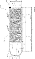
- FIG 1A an example of a yarn storage container comprising a tubular container 101 is shown. More in particular, an axial cross section of such tubular container is provided.
- the tubular container 101 has an axial length L of 72inch in the axial direction 111 and a first (113) and second axial extremity (115).
- Each tubular container is fit for holding one non-wound yarn 200 having a length at least double of the axial length of the tubular container.
- the first axial extremity 113 has an opening 123 for receiving an end of one of the non-wound yarns.
- the second axial extremity 115 of each of the tubular containers is air-permeably closed, e.g. by means of a polymer grid 125 being welded along the circumference of the second axial extremity 115.
- the tubular container 101 has a wall thickness T of 1/8 inch, has a circular radial cross section and an inner diameter D of 2.78 inch.
- the tubular wall 501 comprises two sections, a first section 511 with length Le1 being 54 inch, and a second section 513 with length Le2 being 18 inch.
- the tubular wall has apertures or openings 521 and 523.
- the tubular wall has 4 rows of apertures 521 along its circumference, the rows equidistant one to the other along the circumference.
- Each row has 18 apertures 521 being circular apertures with diameter d1 of 1/8 inch.
- the distance wall-to-wall w1 between the apertures in axial direction is 2.875 inch.
- the distance center to center between the apertures in axial direction is d1+w1 being 3 inch.
- This first section has an inner tube surface area of 487 inch 2 .
- the apertures 521 together provide 0.884 inch 2 open surface. Hence the open areas expressed as % of the surface area of tubular wall in this section 511 is 0.18%.
- the tubular wall has 6 rows of apertures 531 along its circumference, the rows equidistant one to the other along the circumference.
- Each row has 18 apertures or openings 531 being circular apertures with diameter d2 of 1/8 inch.
- the distance wall-to-wall w2 between the apertures in axial direction is 0.875 inch.
- the distance center to center between the apertures or openings in axial direction is d2+w2 being 1 inch.
- This second section has an inner tube surface area of 163 inch 2 .
- the apertures 531 together provide 1.325 inch 2 open surface. Hence the open areas expressed as % of the surface area of tubular wall in this section 531 is 0.82%.
- the inner surface area of the tube is 650 inch 2 , and is provided with in total 2.209 inch 2 open area by means of the apertures in the first and second section.
- the open areas expressed as % of the surface area of tubular wall in its totality is 0.34%.
- FIG. 1B An alternative tubular container 102 is shown in figure 1B .
- the tubular container 102 again has an axial length L of 72 inch in the axial direction 111 and a first (113) and second axial extremity (115).
- Each tubular container is fit for holding one non-wound yarn 200 having a length at least double of the axial length of the tubular container.
- the first axial extremity 113 has a cap 127 provided with an electrically conductive grommet 128 which on its term defines the opening 123 for receiving an end of one of the non-wound yarns.
- the second axial extremity 115 of each of the tubular containers is air-permeably closed, e.g.
- the grommet 128 is a copper grommet with a diameter of the opening of 3 ⁇ 4 inch. Both caps 127 and 126 are made out of polymer. The cap 126 is air permeable as it is provided with a plurality of openings 129.
- the tubular container has a wall provided with apertures or openings identical to the wall set out in figure 1a .
- FIG. 1C An alternative tubular container 103 is shown in figure 1C .
- the tubular container 103 again has an axial length L of 72 inch in the axial direction 111 and a first (113) and second axial extremity (115).
- Each tubular container is fit for holding one non-wound yarn 200 having a length at least double of the axial length of the tubular container.
- the first axial extremity 113 has a cap 130 provided with an electrically conductive tube 131 which on its term defines the opening 123 for receiving an end of one of the non-wound yarns.
- the cap has plurality of small openings 136 along the contact zone where the cap 130 contacts the first axial extremity 113.
- each of the tubular containers is air-permeably closed, e.g. by means of a cap 137 being slid on the container 104 along the circumference of the second axial extremity 115.
- a vacuum system 140 is mount to create a minor lower air pressure in the tubular container 103. Via the openings 136, air is sucked into the tubular container 103 and creates a laminar flow in the tubular container 103 at least along the walls 109 of the tubular containers.
- Caps 130 and 137 are made out of polymer.
- the cap 137 is air permeable as it is provided with a plurality of openings 129.
- the tubular container has a wall provided with apertures or openings identical to the wall set out in figure 1a .
- tubular container 104 again has an axial length L of 72 inch in the axial direction 111 and a first (113) and second axial extremity (115). Each tubular container is fit for holding one non-wound yarn 200 having a length at least double of the axial length of the tubular container.
- the first axial extremity 113 has a cap 135 provided an, optionally electrically conductive, brush 150 which on its defines a circular opening between the bristles 151 of diameter db being 3 ⁇ 4 inch. As such an opening 123 for receiving an end of one of the non-wound yarns is defined.
- the yarn end 200 may contact the bristles 151.
- the second axial extremity 115 of each of the tubular containers is air-permeably closed, e.g. by means of a cap 132 being slid on the container 103 along the circumference of the second axial extremity 115.
- the second axial extremity 115 of each of the tubular containers is air-permeably closed, e.g. by means of a cap 137 being slid on the container 104 along the circumference of the second axial extremity 115.
- Caps 132 and 135 are made out of polymer.
- the cap 132 is air permeable as it is provided with a plurality of openings 129.
- the tubular container has a wall provided with apertures or openings identical to the wall set out in figure 1a .
- tubular containers of figures 1A to 1D may have another radial cross section, e.g. rectangular, square or oval.
- the dimensions of these cross sections may be chosen such that the overall cross sectional surface is about equal to the ones as shown in the figures 1A to 1D .
- the grommets 128, the tubes 131 and/or the circumference of the first axial extremity 113 may be electrically conductive and may be grounded.
- the inner wall 109 may be provided with an electrically conductive layer or strips, which on their turn may also be grounded.
- the tubular containers of figures 1A to 1D comprise a tubular wall made from transparent polystyrene.
- tubular walls 601 to 606, fit for being used as part of the tubular container are shown schematically.
- the tubular wall has two sections 611 and 613.
- the first section 611 comprises 8 rows of circular openings 622, all on a given center to center distance d one to the other in axial direction.
- the section comprises 8 rows of circular openings 622, all on a center to center distance being only d/2 one to the other in axial direction. Therefore, the total open area per surface unit in section613 is double the total open area per surface unit in section 611.
- the first section 611 comprises 4 rows of circular openings 623, all on a given center to center distance d one to the other in axial direction.
- the section comprises 8 rows of identical circular openings 623, all on a center to center distance d one to the other in axial direction. Therefore, the total open area per surface unit in section 613 is double the total open area per surface unit in section 611.
- the section 611 comprises 4 rows of capsule shape like openings 624, all on a given center to center distance d one to the other in axial direction.
- the section comprises 4 rows of n identical capsule shape like openings 624, all on a center to center distance d/2 one to the other in axial direction.
- the section 613 further comprises 4 additional rows intermediately positioned between the other rows.
- Each of these intermediate rows comprise n-1 identical capsule shape like openings 624, with additionally two further openings 625 having a circular shape with surface half of the surface of the capsule shape like openings 624. All openings 624 have their vertical walls parallel with the axial direction of the tubular container. Therefore, the total open area per surface unit in section 613 is double the total open area per surface unit in section 611.
- the section 611 comprises 4 rows of capsule like openings 626, all on a given center to center distance d one to the other in axial direction.
- the section comprises 4 rows of capsule like openings 626, all on a center to center distance being only d/4 one to the other in axial direction. Therefore, the total open area per surface unit in section 613 is quadruple the total open area per surface unit in section 611.
- the section 611 comprises 4 rows of circular openings 627, all on a given center to center distance d one to the other in axial direction.
- the sections In the other section 613, closer to the axial extremities 663, the sections comprise 4 rows of circular openings 626, all on a center to center distance being d one to the other in axial direction.
- the radius of the circular openings 628 is double the radius of the circular openings 627. Therefore, the total open area per surface unit in section 613 is quadruple the total open area per surface unit in section 611.
- the amount of open area per surface unit of tubular wall increase stepwise (with at least one step) along the axial length of the tubular container.
- the tubular wall has no sections but is provided along its length with four rows of openings 629, all being identical and circular shaped. Consecutive openings in a row are on a given center to center distance d one to the other in axial direction. From the first axial extremity 662 towards the second axial extremity 663, the interdistance d between adjacent openings 629 decrease gradually. As such the amount of open area per surface unit of tubular wall increases from first axial extremity 662 towards the second axial extremity 663. Hence the amount of open area per surface unit of tubular wall increase gradually along the axial length of the tubular container.
- tubular containers 1001 are matrix-wise mount in a rack 1002 to form a yarn storage system 1000.
- the rack 1002 is moveably as it is provided with a set of wheels 1004. All tubular containers 1001 are identical, hence have the same length.
- Tubular containers of which the axial cross sections are shown in figures 1A to 1D can be used.
- tubular containers 1001 are mount with the first axial extremities 113 being coplanar in vertical plane 1120.
- the tubular containers 1001 are mount in horizontal position. They are mounted matrix-wise with 6 rows of 6 tubular containers per row. In an alternative version, 9 rows of 18 tubes are mounted in a rack. Between adjacent containers, a distance of 1 ⁇ 4 inch is respected.
- the tubes can be carried by at least two parallel plates provided with a hole, one for each tube. To hold the tubes in place, the tubes are mount in and supported by at least two parallel plates which are provided with openings, each opening to receive one tube.
- the openings in the plates have a diameter substantially equal to the outer diameter of the tubes. The distance center-to-center between two such openings is equal to the diameter of the tube plus 1/4 inch.
- the first plate supports the tubes near the first axial extremities
- the second plate supports the tubes near the second axial extremities.
- a yarn end holding means being a comb-like beam 1005 which comprises at least as much seats as there are tubular containers in the rack 1002.
- the yarns 200 e.g. BCF yarns, for each of the tubular containers, are guided to one of the seats in the beam 1005.
- Such yarn end holding means 1005 is also referred to as comb-spacer or detacheable header.
- the yarn end holding means can be detached from the rest of the yarn storage system 1000.
- FIG 4 An alternative setup of a yarn storage system 2000 is shown in figure 4 .
- the same reference signs refer to the same or similar items.
- the first axial extremities 113 of the tubular containers 1001 are now coplanar according to a horizontal plane 1110.
- a vacuum box 1009 is provided, with which the air permeable second axial extremities are in fluidal connection, i.e. when a vacuum is applied to the box 1009, e.g.by pump 1008, there will be air sucked from each of the second axial extremities, thereby creating a small under-pressure in the inner volume of the tubular containers 1001.
- each of the yarn ends from the yarns 200, extending from the beam 1005, may be coupled to one on one to a needle of a tufting machine (not shown).
- the yarns are taken substantially tension-less from the tubular containers, and are used as pile yarn in the greige.
- a greige with a given relatively short length (the length which can be made with the length of pile yarns residing in the tubular containers) of greige can be made.
- a new yarn storage system replaces the emptied one, is coupled to the tufting machine and a new, potentially short run of a potentially different greige can be made.
- the advantage is that relatively short runs of greige can be provided, while no yarn creel with for each needle a yarn cone, is to be kept at hand.
- a system to execute method to store yarn is schematically shown in figure 5 .
- a yarn storage system 5100 is provided. Examples of such system may be the ones shown in figures 3 or 4 .
- the tubular containers of this yarn storage system 5100 are named 50XY, where X is an integer varying from 1 to N and Y an integer varying from 1 to M, N being the number of rows in the rack, M being the number of columns in the rack.
- a robot 5110 comprises a memory unit 5111 memorizing filling date, being for each tubular container
- the robot comprises an input means 5112 for inputting the filling date in the memory unit.
- This input means may be a keyboard to manually put in the data, or a data reading device reading the data from a data carrier (such as a floppy disk, a USB key or any other similar data storage medium), or may even by just an input port for coupling the memory unit to a computer or the web.
- the robot comprising a control unit 5113 defining the filling sequence of the tubular containers 50XY and controlling the injection of the selected yarn by means of hardware 5114 in the tubular containers while executing the filling sequence.
- three yarn spools each comprising a BCF yarn (A, B and C) are stored in a rack 5100. Though also only one or two yarns may be used, possibly more than 3 yarns are provided such as 4, 5, 6, 7, 8, 9, 10 or more.
- the control unit will select one tubular container 50XY one after the other and reading out the filling data.
- the 3D moveable arm 5024 of the hardware 5014 will pick up the end of the selected yarn from the rack 5100 by its air blowing injector 5125.
- This injector may comprise a vortex injector 5126 which is fed with compresses air from storage 5127 via valve 5128.
- the injector will be brought in front of the opening 123 of the selected tubular container, and will blow the defined length of yarn into the tubular container via opening 123 using compressed air as fluid. Once this length is blown in, the injector may be moved in front of the corresponding opening 1006 of the beam 5005, and blows an end of yarn through the opening 1006.
- the yarn will be a double yarn going through the opening.
- the yarn is cut and either the same yarn is brought in front of the next selected tubular container, or is brought back to the rack 5100, while the injector 5125 selects another yarn to be used to fill the next tubular container. This sequence of actions is repeated until all necessary tubular containers are filled.
- tubular containers may be filled with a given length of yarn, while only a limited number of yarns on a limited number of spools being available.
Landscapes
- Engineering & Computer Science (AREA)
- Textile Engineering (AREA)
- Chemical & Material Sciences (AREA)
- Materials Engineering (AREA)
- Unwinding Of Filamentary Materials (AREA)
- Storage Of Web-Like Or Filamentary Materials (AREA)
- Packages (AREA)
- Yarns And Mechanical Finishing Of Yarns Or Ropes (AREA)
- Spinning Or Twisting Of Yarns (AREA)
- Packaging Of Annular Or Rod-Shaped Articles, Wearing Apparel, Cassettes, Or The Like (AREA)
Abstract
Description
- The present invention relates to yarn storage containers and yarn storage systems, in particular to yarn storage systems for plurality of yarns, such as yarn storage systems for yarns used as pile yarn in tufting processes.
- Tufting machines are known in the art. A large number of yarns, even up to or more than 1000 yarns, are tufted simultaneously into a primary backing to provide a greige product. For each yarn tufted, a yarn cone is held in a rack of yarns.
- When the color or design of the greige fabric is to be changed, e.g. the same design is to be tufted in a f-different color palette or scheme. This may require the replacement of this huge number of cones in the rack. This is labor intensive and time consuming to make one change over.
- It is an object of the present invention to provide a yarn storage systems, which reduces the change over time for changing the greige product made in the tufting industry. It is also the object of the invention to provide yarn storage containers being part of such yarn storage system, and methods to store yarn in such yarn storage system.
- According to a first independent aspect of the invention, a yarn storage container and an yarn storage system are provided.
- According to a first aspect of the invention, a yarn storage container for storing a yarn, said storage container comprising a tubular container, having an axial length, a tubular wall and a first and second axial extremity, the first axial extremity of said tubular container having an opening for receiving an end of a yarn, said second axial extremity of said tubular container being air-permeably closed, said tubular wall is air permeable by means of a plurality of openings present along the axial length of said tubular container.
- The yarn storage container if fit for storing non wound yarn, i.e. yarn in non - would form.
- As such, the tubular wall of the tubular container is air permeable and allows air passing in radial direction, in particularly from the inner side of the tubular container to the outer side of the tubular container. The tubular container hence has a perforated tubular wall.
- Each tubular container is fit for holding one yarn in non-wound form or appearance, having a length at least double of the axial length of the tubular container.
- Yarns which are non-wound are yarns which are not wound or coiled on a spool or bobbin or alike. The yarn is laid down freely and unguided within the void inside the tubular container.
- The second axial extremity of said container may be provided with an air permeable closing cap, such as e.g. a perforated cap from polymer or metal, which fits in or over the axial extremity of the tubular container. Alternatively, the second axial extremity of the tubular container is closed with a grid, e.g. a metal or polymer grid which is attached to the axial extremity. The open area of this air permeable closing cap may be in the range of 30 to 90 % of the total surface of the cap, such as e.g. in the range of 40 to 80%, more preferred n the rang of 45 to 75%.
- A yarn storage system according to a second aspect of the invention comprises a plurality of yarn storage containers according to the first aspect of the invention. The working principle of the yarn storage system according to the invention is based upon the fact that such tubular containers can be filed with yarn by blowing yarn into the tube, e.g. by means of compressed fluid, such as air, via the opening at the first axial extremity of each of the tubular containers. The yarn end blown into the tubular container will be blown against the closure of the second axial extremity, and additional yarn length will gradually fill up the tubular container as the yarn is laid freely in the volume of the tubular container. The fluid blown in, escapes the inner void of the tubular container via the air permeable closure of the second extremity, and/or the openings in the tubular wall. In other words, the yarns stuffs and fills the tubular container at least partially. Once the required length of yarns is provided in the tubular container or containers, the yarn storage system may be moved to the apparatus which is to consume the yarns and convert it into the required textile product. As an example, the yarns may be used by a tufting machine as pile yarn. During consumption of the yarns, the yarns may be gently dragged out of the tubular containers via the opening of the first axial extremity, hence in opposite direction as it was blown in. The yarn taken out of the container, will show very little to no variation on tension, which facilitates the tension control of the yarn during conversion into a textile fabric. The apparatus which is to consume the yarns and convert it into the required textile product may e.g. be a tufting machine, a weaving loom, a warp or weft knitting loom, a sewing or embroidering machine and alike.
- According to some embodiments of a yarn storage container according to the first aspect of the invention, the opening of the first axial extremity of said container for receiving an end of said non-wound yarn may be provided by leaving the first axial extremity of said container uncovered, hence open.
- The tubular container has a perforated tubular wall, i.e. a wall with openings. The openings may have any suitable shape, e.g. circular; polygonal shaped such as triangular, square, rectangular, diamond shaped, pentagonal, hexagonal and alike, optionally all of these polygonal shapes having rounded corners; capsule shaped (i.e. rectangular but terminated with half a circle at the short side of the rectangle); dog bone shaped; elliptic; or alike. At the inner side of the tube, the perforations may have a rim free of burrs. The inner rim of the perforations is preferably flush with the inner surface of the tubular container.
- According to some embodiments the openings in the perforated tubular wall may be circular or rectangular, the latter optionally terminated with half a circle at the short side of the rectangle or having rounded corners. The rectangular opening, optionally terminated with half a circle at the short side of the rectangle (also referred to as capsule-shaped) or having rounded corners, may have its long side parallel or perpendicular to the axial length of the tubular container.
- The openings define a total sum of open area along the tubular wall of the tubular container, hereinafter referred to as "open area". The average open area per surface unit of inner tubular wall may be in the range of 0.1 to 2.5%, more preferred in the range of 0.25 to 1%. Each opening preferably has a surface area in the range of 0.003 to 0.196 inch2, such as in the range of 0.008 to 0.05 inch2.
- Preferably, the openings may be distributed along the tubular wall according to a geometrical pattern.
- According to some embodiments, the amount of open area per surface unit of inner tubular wall adjacent the first axial extremity may be smaller than the amount of open area per surface unit of inner tubular wall adjacent the second axial extremity. The amount of open area per surface unit of inner tubular wall may increase gradually from the first axial extremity to the second axil extremity. According to some embodiments, the amount of open area per surface unit of inner tubular wall may increase stepwise from the first axial extremity to the second axil extremity.
- The amount of open area per surface unit of inner tubular wall may increase stepwise (with at least one step) or gradually along the axial length of the tubular container from the first axial extremity to the second axial extremity. Possibly the amount of open area increases stepwise from the first axial extremity to the second axial extremity. As such different sections along the axial length of the tubular wall of the tubular container are defined.
- The open area per surface unit of tubular wall near the first axial extremity of the tubular container is in the range of 0.1 to 2.5%, more preferred in the range of 0.1 to 1% such as in the range of 0.1 to 0.5%.
The open area per surface of tubular wall near the second axial extremity of the tubular container is in the range of 0.1 to 2.5%, more preferred in the range of 0.5 to 2.5% such as in the range of 0.5 to 1.5%. - The open area may be varied over the surface of the tubular container by varying the number of openings per surface unit, by varying the shape of the openings, by varying the dimensions of the openings or by any combination of these measures.
- According to some embodiments, the inner tubular wall may comprise at least two sections, the amount of open area per surface unit of inner tubular wall in the section adjacent the first axial extremity is less than the amount of open area per surface unit of inner tubular wall in the section adjacent the second axil extremity.
- In some of its preferred embodiments, the tubular wall has two sections, i.e. with length Le1 and Le2, each located adjacent to one of the extremities. The lengths Le1 and Le2 together is the axial length of the tubular container. The length of the section adjacent the first axial extremity may have a length Le1 being 50 to 85% of the total axial length of the container. The length of the section adjacent the second axial extremity may have a length Le2 being 15 to 50% of the total axial length of the container. Preferably Le1 is about 75% of the total axial length of the container, Le2 being about 25% of the axial length of the container.
- The open area expressed as % of the surface area of inner tubular wall of the section adjacent the first axial extremity may be in the range of 0.1 to 2.5%, more preferred in the range of in the range of 0.1 to 1%, such as in the range of 0.1 to 0.5%. The open areas expressed as % of the surface area of inner tubular wall of the section adjacent the second axial extremity may be in the range of0.1 to 2.5%, more preferred in the range of 0.5 to 2.5% such as in the range of 0.5 to 1.5%.
- The openings may be distributed over the tubular wall according to rows of openings parallel between themselves, and aligned in axial direction, i.e. parallel to the axis of the tubular container. The openings may be equidistant within the row within each section. The distances between adjacent openings in a row may vary, e.g. decrease, in case the tubular wall has a varying, e.g. increasing, amount of open area per surface unit of tubular wall. The number of rows of openings may be constant along the axis of the tubular container or may vary between sections. The number of rows of openings may vary, e.g. increase, in case the tubular wall has a varying, e.g. increasing, amount of open area per surface unit of tubular wall for a given section. Or a combination of both these measures may be provided to provide varying open areas along the axial length of the tubular container.
- According to some embodiments , the first axial extremity of said tubular container may comprise a lid substantially closing said first axial extremity, said lid is provided with an hole for providing said opening for receiving an end of the non-wound yarn.
- The first axial extremity of said container may be provided with a lid, such as e.g. a lid from polymer or metal, which fits in and/or over the axial extremity of the tubular container. The lid may be e.g. a plug or a cap. The lid may be removably attached to the first axial extremity. It may be attached by clips or clamps, or just may fit in and/or over the tubular containers first axial extremity, where it fits and stays in place due to friction forces.
- According to some embodiments , the first axial extremity of said tubular container may comprise a grommet for receiving said end of said non-would yarn, said grommet being mechanically coupled to the first axial extremity of said tubular container. The grommet may fit into the hole of a lid substantially closing the first axial extremity.
- The grommet may be part of said lid, thereby providing the opening to the lid. The grommet may be a tube, typically of relative short length, such as 0.5 to 2 inches.
The inner diameter of the tube opening may vary, such as between 0.25 and 2 inches, such as between 0.5 and 1 inches. The grommet may be electrically conductive. - The grommet may be made from metal, such as iron, steel, copper, aluminum, bronze, messing, or any alternative metal alloy, or may be made from electrically conductive polymers, like carbon fiber or carbon powder filled polymer, such as carbon powder filled polypropylene, polyethylene, polyamide , polyvinylchloride or alike. In the alternative, the grommet may be porcelain.
- According to some embodiments the lid may comprise one or a plurality of small openings along the contact zone where said lid contacts said first axial extremity.
- The openings may be small perforations, holes, slits and alike. Via these small openings a laminar air stream may be provided by gently blowing or sucking air through the small openings into the inner volume of the tubular container.
- In general, the yarn storage container according the first aspect of the invention may comprise means for providing a laminar air stream in axial direction from the first axial extremity to the second axial extremity along the walls of the tubular container. This in fact provides a second, independent aspect of the present invention.
- According to some embodiments the first axial extremity of said tubular container may comprise a brush for contacting said end of said yarn.
- The brush may be fitting into a hole provided in a lid which substantially closes the first axial extremity.
Possibly the bristles of the brush close said opening. The bristles contacting the non-wound yarn in or passing through the opening is provided with a minimum of tension when the yarn is drawn out of the container. The brush may be a straight brush with bristles all being substantially parallel, or a circular brush with bristles oriented towards a central point. For a circular brush, the bristles may overlap at the central point, but preferably leave a central opening, e.g. an opening of about ¼" to 1", such as about %". - The bristles may be electrically conductive and may be grounded to reduce the static loading of the yarn passing the opening.
- The storage container may comprise a grounding system for grounding the electrically conductive brush, grommet or tube.
- According to some embodiments, the container may comprise means for providing a laminar air stream in axial direction from the first axial extremity to the second axial extremity at least along the walls of the tubular container.
- According to some embodiments, the container may comprise means to create a sub-atmospheric pressure in the tubular container via the second axial extremity.
- With sub-atmospheric pressure is meant a pressure being less than the ambient pressure. Causing such sub-atmospheric pressure via the second axial extremity, will help the yarn end, and the length of yarn blown into the tubular container, to move more easily and completely up to the second axial extremity. It may also help to increase the amount of yarn that can be introduced in to the tubular container because it may compress the inserted yarn in a direction towards the second axial extremity.
- This means to create sub-atmospheric pressure in combination with lids comprising one or a plurality of small openings along the contact zone where the lid contacts the first axial extremity may be part of, or may be sufficient to provide a means to create a laminar stream along the inner wall of the tubular container.
- According to some embodiments, the tubular container may have, in radial cross section, a circular, oval, square or rectangular cross section profile.
- According to some embodiments, the surface of a radial cross section of the tubular container may be between 0.75 and 13 inch2. More preferred, the surface of a radial cross section of the tubular container may be between 1.5 and 13 inch2, such as between 2 and 13 inch2.
- According to some embodiments, the tubular container may eb provided from steel, aluminum, cardboard or polymer, preferably a polymer chosen from the group consisting of polypropylene, polyethylene, polyamide, polystyrene and polyvinylchloride.
- Preferably the tubular container may be provided from any suitable material, preferably from metal, like aluminum, or polymer, preferably polyvinylchloride (PVC), polyethylene (PE), polypropylene (PP) or polystyrene (PS). The tubular wall is preferably transparent, allowing visual inspection of the yarn stored in the container.
- The tubular containers may have a tubular wall with a thickness which may be between 0.042 inch and 0.1 inch, when the tubular containers are metal or metallic containers. The tubular containers may have a tubular wall with a thickness which may be between 0.0625 and 0.25 inch when the tubular containers are cardboard or polymeric containers.
- According to some embodiments, the tubular container is a cardboard or polymeric tubular container, the inner wall of said tubular container being made electrically conductive.
- The electrical conductivity of the inner wall of the tubular container may be obtained by providing e.g. electrically conductive coating along the whole inner wall,. Alternatively, coating strips in axial direction or a spiraling strip along the length of the tubular container, made out of electroconductive material may be provided. Such electroconductive coating material may e.g. be silver, gold, aluminum or similar metal or metallic coatings.
- As the yarn storage containers form part of a storage system, said system may comprise a grounding system for grounding electrically conductive tubular containers or the inner the electrically conductive inner wall of the tubular containers. This grounding system may be the same grounding system for grounding the electrically conductive grommets.
- According to some embodiments, the axial length of the tubular container may be between 15 and 110 inch. More preferred, the axial length of the tubular containers may be between 20 and 100 inch, such as between 24 and 96 inch.
- According to a second aspect of the invention, a yarn storage system is provided, the system comprising at least two yarn storage containers according to the first aspect of the invention.
- According to some embodiments, all tubular containers may have identical dimensions.
- According to some embodiments, the tubular containers may be organized in a rack.
- One rack may comprise 16 to 1024 tubular containers, more preferred 36 to 1000 containers, which may be organized in a matrix setting. The matrix may comprise 4 to 32 rows and 4 to 32 columns, more preferred 6 to 30 rows and 6 to 30 columns.
- The racks may be provided with a transporting system, rendering the yarn storage system movable. As an example, the rack may be provided with a plurality of wheels.
- According to some embodiments, the first axial extremities of all tubular containers may be coplanar.
- Typically also the second axial extremities of all tubular containers are coplanar as preferably all tubular containers are of equal length, and preferably are identical.
- According to some embodiments, the tubular containers may be oriented in a vertical position. According to some embodiments, the tubular containers may be oriented in a horizontal position.
- Each tubular container may be provided with at least one yarn detector, e.g. an electronical, mechanical or optical yarn detector, detecting the presence of a yarn at the opening of the first axial extremity of said containers. The yarn detectors may be part of a yarn detecting system, further equipped with a processing unit to receive signals of said yarn presence detectors indicating the presence or non-presence of yarns, and a signal generating means to generate a signal when at least one yarn detector fails to detect a yarn. Then the yarn storage system cooperates with machinery consuming yarn, e.g. a tufting machine, this machine may use the signal of said yarn detecting system to interrupt its yarn consumption when one or more tubular containers fail to have a yarn present, e.g. when it ran out of yarn stored in said tubular container.
- According to some embodiments, the yarn storage system further may comprise a yarn end holding means comprising a number of apertures or slots, said number of apertures or slots being identical or more that the number of tubular containers of the yarn storage system, each aperture or slot being fit to receive one yarn end from one of the tubular containers.
- The apertures or slots may all be adjacent one next to the other in a row, or may be organized in two or more rows, optionally in zig-zag setup. Each slot or aperture may be provided with a ceramic tube to prevent the passing yarn to wear out the aperture or slot.
- The yarn end holding means typically may be provided as a beam, i.e. rectangular, balk-like piece of metal or plastic in which the apertures or slits are provided. Most preferably the yarn end holding means has a comb-like structure
- According to a third independent aspect of the invention, a yarn storage system is used to supply textile machinery with yarn.
- According to some embodiments, the use of a yarn storage system according to the second aspect of the invention is provided, for providing yarn to a textile machine, such as to provide pile yarn to a tufting machine.
- The yarn storage system may be used to store bulked continuous filament yarns, such as used by tufting machines to provide pile yarn of the tufted greige, hence of the tufted carpet.
- It is clear that the yarn storage system may as well be used to provide yarns to any other textile producing equipment, such as warp knitting machines, as warp yarn for weaving looms, such as carpet weaving looms, and alike.
- According to a fourth independent aspect of the invention, a method to store yarns in provided.
- The method to store yarn according to this aspect comprises the steps of
- a) Providing a yarn storage system according to the second aspect of the invention;
- b) Providing N spools of yarn, N being an integer equal or more than 1;
- c) Repeating
- ∘ selecting one tubular container to at least partially be filed with yarn of said spool;
- ∘ defining for said selected tubular container the length of yarn to be inserted;
- ∘ selecting one of the N yarns;
- ∘ Injecting said defined length of said selected yarn from said spool by means of a fluid, such as pressured air, in the selected tubular container;
- According to some embodiments, the N may be more than 1. Preferably the number of yarns used will be between 2 and 10, even more preferably between 2 and 8, such as 3, 4, 5, 6, 7 or 7 yarns.
- According to some embodiments, the injecting of said yarn in said tubular containers may be performed by a robot, comprising a spool rack comprising said N spools of yarn.
- According to some embodiments, the robot may comprise a memory unit memorizing filling date, being for each tubular container memorizing
- its position,
- the yarn to be selected and
- the length of yarn to be injected;
- The robot hence fills each tubular container with the correct yarn. It first ensures it select the yarn end needed to fill the next tubular container, brings its injection instrument in front of the opening at the axial extremity of the selected tubular container, and injects yarn while measuring the length of yarn, either directly or indirectly.
- According to some embodiments, when N>1, the yarns of said N spools of yarn all may be mutually different yarns.
- The yarns may e.g. differ in color or color tone, or may have a different linear weight or composition.
- According to some embodiments, the yarns may be bulked continuous filament yarns.
- More preferably the yarns used are so-called direct tuft yarn, which are yarns being more delicate as compared to standard BCF yarn.
- According to some embodiments, the defined lengths of yarns may be in the range of 2000 to 10000 ft.
- More preferred, the injected lengths are in the range of 2000 to 10000 ft of yarn, even more preferred in the range of 3500 to 7500 ft of yarn.
- It is understood that any type of yarn can be held in the yarn storage system. Yarns with a titer (i.e. the weight per length unit) in the range of 900 to 4000 denier may be stored, such as in the range of 1100 to 3600 denier.
- According to some embodiments, the system may comprise a vortex injector for injecting said defined length of said selected yarn in the selected tubular container.
- The vortex injector preferably uses 2 to 15 cubic foot per minute (CFM), more preferred 3 to 8 CFM such as 5 to 8 CFM. The latter is in particularly advantageous when direct tuft yarn is used.
The method has the advantage that with a limited number of spools of yarns, a wide variety of organized yarn storage can be provided. The yarn storage being organized meaning that it is known for each tubular container, which yarn is contained and at which length. As such a plurality of yarns can be made ready for use, e.g. by a tufting machine, providing one yarn end for each needle of the tuft machine, while only a limited number of spools need to be at hand. The lengths of the yarns in the tubular containers can be measured accurately and may be only limited. As such a given "minor" length of a tufted greige carpet can be provided with little yarn waste being created. The latter because the yarn length in the containers can be calculated according to the yarn which will be consumed by the tufting machine to make the length of greige. For each kind of yarn or yarn color needed, only the number of spools are to be provided which together comprise the needed length of yarn. Only the leftovers on these spools used might be seen as waste. The number of spools is not linked to the number of needles in the tufting machine, hence a very significant waste reduction is obtained. - The possibility to move the yarn storage system enables the skilled person to fill the yarn storage system at a dedicated location where the robot is present. The filled and emptied yarn storage systems can move to the position where the textile machine will take out the yarn, which cause only limited storage place is needed as compared with yarn creels carrying the same number of spools as now tubular containers are present.
- According to a further, fifth aspect of the invention, a yarn storage container is provided, similar to the yarn storage container of the first aspect of the invention, however where the tubular wall of the tubular container are air tight, i.e. they do not have openings along their axial length. In particular yarn storage containers with a tubular container with a limited axial length are provided as such, e.g. with axial lengths of less than or equal to 1.5m, e.g. less than or equal to 1m. such tubular containers preferably have a circular cross section with a diameter preferably less than 4 inch.
According to this aspect, a yarn storage container for storing a yarn is provided, said storage container comprising a tubular container, having an axial length, a tubular wall and a first and second axial extremity, the first axial extremity of said tubular container having an opening for receiving an end of a yarn, said second axial extremity of said tubular container being air-permeably closed, said tubular wall is air impermeable.
All features of the yarn storage containers according to the first aspect of the invention, which features are not related to the air permeability of the tubular wall, can be applied for the yarn storage containers of this fifth aspect. - According to a sixth aspect, a plurality of yarn storage containers can be used to provide a yarn storage system according to this sixth aspect of the invention. All features of the yarn storage system according to the second aspect of the invention, which features are not related to the air permeability of the tubular wall, can be applied for the yarn storage containers of this sixth aspect.
- According to a seventh aspect of the invention, a yarn storage system according to the sixth aspect is used to supply textile machinery with yarn. It is clear that this yarn storage system may be used to provide yarns to any textile producing equipment, such as tufting looms, warp knitting machines, as warp yarn for weaving looms, such as carpet weaving looms, and alike.
- According to a further eight aspect of the invention, a method to store yarns in provided.
- The method to store yarn according to this aspect comprises the steps of
- a) Providing a yarn storage system according to the sixth aspect of the invention;
- b) Providing N spools of yarn, N being an integer equal or more than 1;
- c) Repeating
- ∘ selecting one tubular container to at least partially be filed with yarn of said spool;
- ∘ defining for said selected tubular container the length of yarn to be inserted;
- ∘ selecting one of the N yarns;
- ∘ Injecting said defined length of said selected yarn from said spool by means of a fluid, such as pressured air, in the selected tubular container;
- The independent and dependent claims set out particular and preferred features of the invention. Features from the dependent claims may be combined with features of the independent or other dependent claims, and/or with features set out in the description above and/or hereinafter as appropriate.
- The above and other characteristics, features and advantages of the present invention will become apparent from the following detailed description, taken in conjunction with the accompanying drawings, which illustrate, by way of example, the principles of the invention. This description is given for the sake of example only, without limiting the scope of the invention. The reference figures quoted below refer to the attached drawings.
-
-
Figure 1A to 1D are schematically views of tubular containers from a yarn storage system according to the invention. -
Figure 2 are schematically views of tubular containers from a yarn storage system according to the invention -
Figure 3 and 4 are schematically views of yarn storage systems according to the invention. -
Figure 5 schematically represents a method to store yarn in a yarn storage system according to the invention. - The same reference signs refer to the same, similar or analogous elements in the different figures.
- The present invention will be described with respect to particular embodiments. It is to be noticed that the term "comprising", used in the claims, should not be interpreted as being restricted to the means listed thereafter; it does not exclude other elements or steps. It is thus to be interpreted as specifying the presence of the stated features, steps or components as referred to, but does not preclude the presence or addition of one or more other features, steps or components, or groups thereof. Thus, the scope of the expression "a device comprising means A and B" should not be limited to devices consisting only of components A and B. It means that with respect to the present invention, the only relevant components of the device are A and B.
- Throughout this specification, reference to "one embodiment" or "an embodiment" are made. Such references indicate that a particular feature, described in relation to the embodiment is included in at least one embodiment of the present invention. Thus, appearances of the phrases "in one embodiment" or "in an embodiment" in various places throughout this specification are not necessarily all referring to the same embodiment, though they could.
- Furthermore, the particular features or characteristics may be combined in any suitable manner in one or more embodiments, as would be apparent to one of ordinary skill in the art.
- According to a first independent aspect of the invention, a yarn storage system is provided.
- A yarn storage system for storing a multiple non-wound yarns will be described hereinafter by making use of the figures. In
figure 1A , an example of a yarn storage container comprising atubular container 101 is shown. More in particular, an axial cross section of such tubular container is provided. Thetubular container 101 has an axial length L of 72inch in theaxial direction 111 and a first (113) and second axial extremity (115). Each tubular container is fit for holding onenon-wound yarn 200 having a length at least double of the axial length of the tubular container. The firstaxial extremity 113 has anopening 123 for receiving an end of one of the non-wound yarns. The secondaxial extremity 115 of each of the tubular containers is air-permeably closed, e.g. by means of apolymer grid 125 being welded along the circumference of the secondaxial extremity 115.
Thetubular container 101 has a wall thickness T of 1/8 inch, has a circular radial cross section and an inner diameter D of 2.78 inch. - The
tubular wall 501 comprises two sections, afirst section 511 with length Le1 being 54 inch, and asecond section 513 with length Le2 being 18 inch. In each of the sections, the tubular wall has apertures oropenings section 511, the tubular wall has 4 rows ofapertures 521 along its circumference, the rows equidistant one to the other along the circumference. Each row has 18apertures 521 being circular apertures with diameter d1 of 1/8 inch. The distance wall-to-wall w1 between the apertures in axial direction is 2.875 inch. The distance center to center between the apertures in axial direction is d1+w1 being 3 inch. This first section has an inner tube surface area of 487 inch2. Theapertures 521 together provide 0.884 inch2 open surface. Hence the open areas expressed as % of the surface area of tubular wall in thissection 511 is 0.18%. - In
section 513, the tubular wall has 6 rows of apertures 531 along its circumference, the rows equidistant one to the other along the circumference. Each row has 18 apertures or openings 531 being circular apertures with diameter d2 of 1/8 inch. The distance wall-to-wall w2 between the apertures in axial direction is 0.875 inch. The distance center to center between the apertures or openings in axial direction is d2+w2 being 1 inch. This second section has an inner tube surface area of 163 inch2. The apertures 531 together provide 1.325 inch2 open surface. Hence the open areas expressed as % of the surface area of tubular wall in this section 531 is 0.82%. - In total, the inner surface area of the tube is 650 inch2, and is provided with in total 2.209 inch2 open area by means of the apertures in the first and second section. The open areas expressed as % of the surface area of tubular wall in its totality is 0.34%.
- An alternative
tubular container 102 is shown infigure 1B . Thetubular container 102 again has an axial length L of 72 inch in theaxial direction 111 and a first (113) and second axial extremity (115). Each tubular container is fit for holding onenon-wound yarn 200 having a length at least double of the axial length of the tubular container. The firstaxial extremity 113 has acap 127 provided with an electricallyconductive grommet 128 which on its term defines theopening 123 for receiving an end of one of the non-wound yarns. The secondaxial extremity 115 of each of the tubular containers is air-permeably closed, e.g. by means of acap 126 being slid in thecontainer 102 along the circumference of the secondaxial extremity 115.
Thegrommet 128 is a copper grommet with a diameter of the opening of ¾ inch. Both caps 127 and 126 are made out of polymer. Thecap 126 is air permeable as it is provided with a plurality ofopenings 129.
The tubular container has a wall provided with apertures or openings identical to the wall set out infigure 1a . - An alternative
tubular container 103 is shown infigure 1C . Thetubular container 103 again has an axial length L of 72 inch in theaxial direction 111 and a first (113) and second axial extremity (115). Each tubular container is fit for holding onenon-wound yarn 200 having a length at least double of the axial length of the tubular container. The firstaxial extremity 113 has acap 130 provided with an electricallyconductive tube 131 which on its term defines theopening 123 for receiving an end of one of the non-wound yarns. The cap has plurality ofsmall openings 136 along the contact zone where thecap 130 contacts the firstaxial extremity 113. The secondaxial extremity 115 of each of the tubular containers is air-permeably closed, e.g. by means of acap 137 being slid on thecontainer 104 along the circumference of the secondaxial extremity 115.
To the outer end of thecap 137, avacuum system 140 is mount to create a minor lower air pressure in thetubular container 103. Via theopenings 136, air is sucked into thetubular container 103 and creates a laminar flow in thetubular container 103 at least along thewalls 109 of the tubular containers.
Caps openings 129.
The tubular container has a wall provided with apertures or openings identical to the wall set out infigure 1a . - Still another alternative
tubular container 104 is shown infigure 1D . Thetubular container 104 again has an axial length L of 72 inch in theaxial direction 111 and a first (113) and second axial extremity (115). Each tubular container is fit for holding onenon-wound yarn 200 having a length at least double of the axial length of the tubular container. The firstaxial extremity 113 has acap 135 provided an, optionally electrically conductive,brush 150 which on its defines a circular opening between thebristles 151 of diameter db being ¾ inch. As such anopening 123 for receiving an end of one of the non-wound yarns is defined. Theyarn end 200 may contact thebristles 151. The secondaxial extremity 115 of each of the tubular containers is air-permeably closed, e.g. by means of acap 132 being slid on thecontainer 103 along the circumference of the second axial extremity 115.The secondaxial extremity 115 of each of the tubular containers is air-permeably closed, e.g. by means of acap 137 being slid on thecontainer 104 along the circumference of the secondaxial extremity 115.Caps cap 132 is air permeable as it is provided with a plurality ofopenings 129.
The tubular container has a wall provided with apertures or openings identical to the wall set out infigure 1a . - In the alternative, the tubular containers of
figures 1A to 1D may have another radial cross section, e.g. rectangular, square or oval. The dimensions of these cross sections may be chosen such that the overall cross sectional surface is about equal to the ones as shown in thefigures 1A to 1D .
Thegrommets 128, thetubes 131 and/or the circumference of the firstaxial extremity 113 may be electrically conductive and may be grounded.
Optionally theinner wall 109 may be provided with an electrically conductive layer or strips, which on their turn may also be grounded.
The tubular containers offigures 1A to 1D comprise a tubular wall made from transparent polystyrene. - In
figure 2a to 2f , several suitabletubular walls 601 to 606, fit for being used as part of the tubular container are shown schematically. Infigure 2a to 2e , the tubular wall has twosections
Infigure 2a , thefirst section 611 comprises 8 rows ofcircular openings 622, all on a given center to center distance d one to the other in axial direction. In the other section613, closer to the secondaxial extremity 663, the section comprises 8 rows ofcircular openings 622, all on a center to center distance being only d/2 one to the other in axial direction. Therefore, the total open area per surface unit in section613 is double the total open area per surface unit insection 611. - In
figure 2b , thefirst section 611 comprises 4 rows ofcircular openings 623, all on a given center to center distance d one to the other in axial direction. In theother section 613, closer to the secondaxial extremity 663, the section comprises 8 rows of identicalcircular openings 623, all on a center to center distance d one to the other in axial direction. Therefore, the total open area per surface unit insection 613 is double the total open area per surface unit insection 611. - In
figure 2c , thesection 611 comprises 4 rows of capsule shape likeopenings 624, all on a given center to center distance d one to the other in axial direction. In theother section 613, closer to theaxial extremity 663, the section comprises 4 rows of n identical capsule shape likeopenings 624, all on a center to center distance d/2 one to the other in axial direction. Thesection 613 further comprises 4 additional rows intermediately positioned between the other rows. Each of these intermediate rows comprise n-1 identical capsule shape likeopenings 624, with additionally twofurther openings 625 having a circular shape with surface half of the surface of the capsule shape likeopenings 624. Allopenings 624 have their vertical walls parallel with the axial direction of the tubular container.
Therefore, the total open area per surface unit insection 613 is double the total open area per surface unit insection 611. - In
figure 2d , thesection 611 comprises 4 rows of capsule likeopenings 626, all on a given center to center distance d one to the other in axial direction. In theother section 613, closer to theaxial extremity 663, the section comprises 4 rows of capsule likeopenings 626, all on a center to center distance being only d/4 one to the other in axial direction. Therefore, the total open area per surface unit insection 613 is quadruple the total open area per surface unit insection 611. - In
figure 2e , thesection 611 comprises 4 rows ofcircular openings 627, all on a given center to center distance d one to the other in axial direction. In theother section 613, closer to theaxial extremities 663, the sections comprise 4 rows ofcircular openings 626, all on a center to center distance being d one to the other in axial direction. The radius of the circular openings 628 is double the radius of thecircular openings 627. Therefore, the total open area per surface unit insection 613 is quadruple the total open area per surface unit insection 611. - For all embodiments in
figures 2a to 2e , the amount of open area per surface unit of tubular wall increase stepwise (with at least one step) along the axial length of the tubular container. - In
figure 2f , the tubular wall has no sections but is provided along its length with four rows ofopenings 629, all being identical and circular shaped.
Consecutive openings in a row are on a given center to center distance d one to the other in axial direction. From the firstaxial extremity 662 towards the secondaxial extremity 663, the interdistance d betweenadjacent openings 629 decrease gradually.
As such the amount of open area per surface unit of tubular wall increases from firstaxial extremity 662 towards the secondaxial extremity 663. Hence the amount of open area per surface unit of tubular wall increase gradually along the axial length of the tubular container. - The skilled person understands that the various measures taken to locally modify the amount of open area per surface unit of tubular wall as applied in
figures 2a to 2f may be combined to vary this open area per surface unit of tubular wall. - As shown in
figure 3 , a plurality of suchtubular containers 1001 are matrix-wise mount in arack 1002 to form ayarn storage system 1000. Therack 1002 is moveably as it is provided with a set ofwheels 1004. Alltubular containers 1001 are identical, hence have the same length. Tubular containers of which the axial cross sections are shown infigures 1A to 1D can be used. - Using the tubes as shown in
figures 1A to 1D , 36tubular containers 1001 are mount with the firstaxial extremities 113 being coplanar invertical plane 1120. Thetubular containers 1001 are mount in horizontal position. They are mounted matrix-wise with 6 rows of 6 tubular containers per row. In an alternative version, 9 rows of 18 tubes are mounted in a rack. Between adjacent containers, a distance of ¼ inch is respected. The tubes can be carried by at least two parallel plates provided with a hole, one for each tube. To hold the tubes in place, the tubes are mount in and supported by at least two parallel plates which are provided with openings, each opening to receive one tube. The openings in the plates have a diameter substantially equal to the outer diameter of the tubes. The distance center-to-center between two such openings is equal to the diameter of the tube plus 1/4 inch. The first plate supports the tubes near the first axial extremities, the second plate supports the tubes near the second axial extremities. - In front of the
side 1100 providing theopenings 123 of thetubular containers 1001, a yarn end holding means being a comb-like beam 1005 is provided which comprises at least as much seats as there are tubular containers in therack 1002. Theyarns 200, e.g. BCF yarns, for each of the tubular containers, are guided to one of the seats in thebeam 1005. Such yarn end holding means 1005 is also referred to as comb-spacer or detacheable header. The yarn end holding means can be detached from the rest of theyarn storage system 1000. - An alternative setup of a
yarn storage system 2000 is shown infigure 4 . The same reference signs refer to the same or similar items. The firstaxial extremities 113 of thetubular containers 1001 are now coplanar according to ahorizontal plane 1110. At the lower side of the rack, avacuum box 1009 is provided, with which the air permeable second axial extremities are in fluidal connection, i.e. when a vacuum is applied to thebox 1009, e.g.bypump 1008, there will be air sucked from each of the second axial extremities, thereby creating a small under-pressure in the inner volume of thetubular containers 1001. - For
figures 3 and 4 , each of the yarn ends from theyarns 200, extending from thebeam 1005, may be coupled to one on one to a needle of a tufting machine (not shown). During providing of the greige by the tufting machine, the yarns are taken substantially tension-less from the tubular containers, and are used as pile yarn in the greige. A greige with a given relatively short length (the length which can be made with the length of pile yarns residing in the tubular containers) of greige can be made. Once finished, a new yarn storage system replaces the emptied one, is coupled to the tufting machine and a new, potentially short run of a potentially different greige can be made. The advantage is that relatively short runs of greige can be provided, while no yarn creel with for each needle a yarn cone, is to be kept at hand. - A system to execute method to store yarn is schematically shown in
figure 5 . - A
yarn storage system 5100 is provided. Examples of such system may be the ones shown infigures 3 or 4 . The tubular containers of thisyarn storage system 5100 are named 50XY, where X is an integer varying from 1 to N and Y an integer varying from 1 to M, N being the number of rows in the rack, M being the number of columns in the rack. - A
robot 5110 comprises amemory unit 5111 memorizing filling date, being for each tubular container - its position (X and Y),
- the yarn (in this case yarn A, B or C) to be selected and
- the length of yarn to be injected
- and optionally, then the yarn storage system comprises a yarn end holding means, like a beam, the position of the opening in the yarn end holding means.
- The robot comprises an input means 5112 for inputting the filling date in the memory unit. This input means may be a keyboard to manually put in the data, or a data reading device reading the data from a data carrier (such as a floppy disk, a USB key or any other similar data storage medium), or may even by just an input port for coupling the memory unit to a computer or the web.
The robot comprising acontrol unit 5113 defining the filling sequence of the tubular containers 50XY and controlling the injection of the selected yarn by means ofhardware 5114 in the tubular containers while executing the filling sequence.
In this embodiment, three yarn spools each comprising a BCF yarn (A, B and C) are stored in arack 5100. Though also only one or two yarns may be used, possibly more than 3 yarns are provided such as 4, 5, 6, 7, 8, 9, 10 or more. - During filling, the control unit will select one tubular container 50XY one after the other and reading out the filling data. The 3D moveable arm 5024 of the hardware 5014, will pick up the end of the selected yarn from the
rack 5100 by itsair blowing injector 5125. This injector may comprise avortex injector 5126 which is fed with compresses air fromstorage 5127 viavalve 5128. The injector will be brought in front of theopening 123 of the selected tubular
container, and will blow the defined length of yarn into the tubular container viaopening 123 using compressed air as fluid.
Once this length is blown in, the injector may be moved in front of thecorresponding opening 1006 of the beam 5005, and blows an end of yarn through theopening 1006. The yarn will be a double yarn going through the opening. The yarn is cut and either the same yarn is brought in front of the next selected tubular container, or is brought back to therack 5100, while theinjector 5125 selects another yarn to be used to fill the next tubular container. This sequence of actions is repeated until all necessary tubular containers are filled. - A such, numerous tubular containers may be filled with a given length of yarn, while only a limited number of yarns on a limited number of spools being available.
- It is to be understood that although preferred embodiments and/or materials have been discussed for providing embodiments according to the present invention, various modifications or changes may be made without departing from the scope and spirit of this invention.
All features of the method according to the fourth aspect of the invention, which features are not related to the air permeability of the tubular wall, can be applied to these methods of this eight aspect.
Claims (16)
- Yarn storage container for storing a yarn, said storage container comprising a tubular container, having an axial length, a tubular wall and a first and second axial extremity, the first axial extremity of said tubular container having an opening for receiving an end of a yarn, said second axial extremity of said tubular container being air-permeably closed, said tubular wall is air permeable by means of a plurality of openings present along the axial length of said tubular container.
- A yarn storage container as in claim 1, wherein the openings are circular or rectangular, the latter optionally terminated with half a circle at the short side of the rectangle or having rounded corners.
- A yarn storage container according to any one of the claims 1 to 2, wherein the amount of open area per surface unit of inner tubular wall adjacent the first axial extremity is smaller than the amount of open area per surface unit of inner tubular wall adjacent the second axial extremity.
- A yarn storage container according to claim 3, wherein the amount of open area per surface unit of inner tubular wall increases gradually from the first axial extremity to the second axil extremity.
- A yarn storage container according to claim 3, wherein the amount of open area per surface unit of inner tubular wall increases stepwise from the first axial extremity to the second axil extremity.
- A yarn storage container according to claim 5, wherein the inner tubular wall comprises at least two sections, the amount of open area per surface unit of inner tubular wall in the section adjacent the first axial extremity is less than the amount of open area per surface unit of inner tubular wall in the section adjacent the second axil extremity.
- A yarn storage container according to any one of the claims 1 to 5, wherein said first axial extremity of said tubular container comprises a lid substantially closing said first axial extremity, said lid is provided with an hole for providing said opening for receiving an end of the non-wound yarn.
- A yarn storage container as in any one of the claims 1 to 7, wherein said first axial extremity of said tubular container comprises a brush for contacting said end of said yarn.
- A yarn storage container according to any one of the claims 1 to 17, wherein the axial length of the tubular container is between 15 and 110 inch.
- A yarn storage system comprising at least two yarn storage containers according to any one of the claims 1 to 9.
- A yarn storage system according to claim 10, wherein said tubular containers are organized in a rack.
- The use of a yarn storage system according to any one of the claims 10 to 11 to provide pile yarn to a tufting machine.
- A method to store yarn, said method comprises the steps ofa) Providing a yarn storage system according to any one of the claims 10 to 11;b) Providing N spools of yarn, N being an integer equal or more than 1;c) Repeating∘ selecting one tubular container to at least partially be filed with yarn of said spool;∘ defining for said selected tubular container the length of yarn to be inserted;∘ selecting one of the N yarns;∘ Injecting said defined length of said selected yarn from said spool by means of a fluid, such as pressured air, in the selected tubular container;For a plurality of tubular containers, optionally until all tubular containers are at least partially filled with yarn.
- A method according to claim 13, wherein N is more than 1.
Preferably the number of yarns used will be between 2 and 10, even more preferably between 2 and 8, such as 3, 4, 5, 6, 7 or 7 yarns. - A method according to claim 13 or 14, wherein injecting said yarn in said tubular containers is performed by a robot, comprising a spool rack comprising said N spools of yarn.
- A yarn storage container for storing a yarn is provided, said storage container comprising a tubular container, having an axial length, a tubular wall and a first and second axial extremity, the first axial extremity of said tubular container having an opening for receiving an end of a yarn, said second axial extremity of said tubular container being air-permeably closed, said tubular wall is air impermeable.
Priority Applications (8)
| Application Number | Priority Date | Filing Date | Title |
|---|---|---|---|
| US17/757,114 US12214987B2 (en) | 2019-12-19 | 2020-12-18 | Yarn storage system and method for producing textiles using such yarn storage system |
| EP20901410.9A EP4077140A4 (en) | 2019-12-19 | 2020-12-18 | YARN STORAGE SYSTEM AND METHOD FOR MANUFACTURING TEXTILES USING SAID YARN STORAGE SYSTEM |
| CN202080088104.6A CN114845935B (en) | 2019-12-19 | 2020-12-18 | Yarn storage system and method for producing textile products using such a yarn storage system |
| PCT/US2020/065832 WO2021127326A1 (en) | 2019-12-19 | 2020-12-18 | Yarn storage system and method for producing textiles using such yarn storage system |
| CA3161637A CA3161637A1 (en) | 2019-12-19 | 2020-12-18 | Yarn storage system and method for producing textiles using such yarn storage system |
| US18/999,612 US12331434B2 (en) | 2019-12-19 | 2024-12-23 | Yarn storage system and method for producing textiles using such yarn storage system |
| US19/191,487 US12421072B2 (en) | 2019-12-19 | 2025-04-28 | Yarn storage system and method for producing textiles using such yarn storage system |
| US19/310,584 US20250376351A1 (en) | 2019-12-19 | 2025-08-26 | Yarn storage system and method for producing textiles using such yarn storage system |
Applications Claiming Priority (2)
| Application Number | Priority Date | Filing Date | Title |
|---|---|---|---|
| US201962950537P | 2019-12-19 | 2019-12-19 | |
| US202062960495P | 2020-01-13 | 2020-01-13 |
Publications (2)
| Publication Number | Publication Date |
|---|---|
| EP3838823A1 true EP3838823A1 (en) | 2021-06-23 |
| EP3838823B1 EP3838823B1 (en) | 2025-10-29 |
Family
ID=69630115
Family Applications (2)
| Application Number | Title | Priority Date | Filing Date |
|---|---|---|---|
| EP20154821.1A Active EP3838823B1 (en) | 2019-12-19 | 2020-01-31 | Yarn storage container and yarn storage system |
| EP20901410.9A Pending EP4077140A4 (en) | 2019-12-19 | 2020-12-18 | YARN STORAGE SYSTEM AND METHOD FOR MANUFACTURING TEXTILES USING SAID YARN STORAGE SYSTEM |
Family Applications After (1)
| Application Number | Title | Priority Date | Filing Date |
|---|---|---|---|
| EP20901410.9A Pending EP4077140A4 (en) | 2019-12-19 | 2020-12-18 | YARN STORAGE SYSTEM AND METHOD FOR MANUFACTURING TEXTILES USING SAID YARN STORAGE SYSTEM |
Country Status (5)
| Country | Link |
|---|---|
| US (4) | US12214987B2 (en) |
| EP (2) | EP3838823B1 (en) |
| CN (1) | CN114845935B (en) |
| CA (1) | CA3161637A1 (en) |
| WO (1) | WO2021127326A1 (en) |
Cited By (1)
| Publication number | Priority date | Publication date | Assignee | Title |
|---|---|---|---|---|
| US20250083924A1 (en) * | 2020-08-06 | 2025-03-13 | Columbia Insurance Company | Methods And Devices For Transporting Yarn |
Families Citing this family (3)
| Publication number | Priority date | Publication date | Assignee | Title |
|---|---|---|---|---|
| LU504424B1 (en) * | 2023-06-06 | 2024-12-06 | Saurer Spinning Solutions Gmbh & Co Kg | shell magazine |
| EP4743382A2 (en) * | 2023-07-13 | 2026-05-20 | Aladdin Mfg Corp | Yarn storage system and method for producing textiles using such a yarn storage system |
| CN118274581A (en) * | 2024-03-27 | 2024-07-02 | 浙江恒逸石化有限公司 | Ingot processing method, device, equipment and storage medium |
Citations (5)
| Publication number | Priority date | Publication date | Assignee | Title |
|---|---|---|---|---|
| US2741009A (en) * | 1951-04-04 | 1956-04-10 | Owens Corning Fiberglass Corp | Method of and apparatus for the high speed packaging of filamentary or strand-like materials |
| US3159902A (en) * | 1961-04-06 | 1964-12-08 | Onderzoekings Inst Res | Method for the manipulation of crimped yarns |
| GB1217671A (en) * | 1966-10-07 | 1970-12-31 | John Frankland Waring | Process and apparatus for handling yarn |
| US4479518A (en) * | 1980-11-28 | 1984-10-30 | Societe Alsacienne De Constructions Mecaniques De Mulhouse | Method and device for forming a filling-yarn reserve for looms |
| EP2885235A1 (en) * | 2012-08-14 | 2015-06-24 | Invista Technologies S.à.r.l. | Yarn packaging and delivery system |
Family Cites Families (68)
| Publication number | Priority date | Publication date | Assignee | Title |
|---|---|---|---|---|
| US179849A (en) * | 1876-07-18 | Improvement in the methods of baling and packing cotton | ||
| US1313294A (en) * | 1919-08-19 | hathaway and c | ||
| FR325378A (en) * | 1902-10-17 | 1903-04-28 | Cadet Charles Louis | A reinforced wood fiber spinning pot with ventilation holes |
| US1024421A (en) * | 1909-01-26 | 1912-04-23 | Paul Sabonadier | Method of preparing warp for manufacturing pile fabric. |
| GB191103580A (en) * | 1911-02-13 | 1911-11-02 | James Anderton Sutcliffe | Improvements in Sliver Cans. |
| US1130841A (en) * | 1914-10-01 | 1915-03-09 | John Bromley & Sons | Pattern-setting machine. |
| US1353613A (en) * | 1919-04-23 | 1920-09-21 | James H Renton | Cop-making apparatus |
| US1877783A (en) * | 1930-02-03 | 1932-09-20 | Worcester Loom Works | Tuft yarn setting frame |
| US1940478A (en) * | 1931-07-03 | 1933-12-19 | Abbott Machine Co | Textile mechanism |
| US2149766A (en) * | 1938-06-15 | 1939-03-07 | Gritman Joseph Harley | Thread carrying cone |
| US2281983A (en) * | 1941-03-07 | 1942-05-05 | Jr George B Markle | Self-locking arbor for tubes and spools or the like |
| US2477744A (en) * | 1944-02-01 | 1949-08-02 | Celanese Corp | Textile operation |
| GB603797A (en) * | 1945-10-30 | 1948-06-23 | Abbott Machine Co | Improvements in packaging textile yarn |
| US2664671A (en) * | 1951-04-04 | 1954-01-05 | Int Harvester Co | Receiving mechanism for drawn glass strands |
| US2952891A (en) * | 1953-03-20 | 1960-09-20 | Robinson Philip Worth | Setting of axminster spools |
| US2863208A (en) * | 1953-12-29 | 1958-12-09 | Owens Corning Fiberglass Corp | Method for packaging a continuous strand |
| US2936964A (en) * | 1957-02-22 | 1960-05-17 | Tigges Gerhard | Yarn supporting reel |
| GB966294A (en) * | 1960-04-05 | 1964-08-12 | Mackie & Sons Ltd J | Improvements relating to textile machines |
| GB1117051A (en) * | 1963-09-17 | 1968-06-12 | Seiset Ltd | Improvements in or relating to the setting of axminster spools |
| US3279639A (en) * | 1965-05-19 | 1966-10-18 | Burlington Industries Inc | Textile sliver can |
| US3397437A (en) * | 1966-11-08 | 1968-08-20 | Mcneill Spinning Company Inc | Method and apparatus for conveying yarn |
| US3601326A (en) * | 1969-07-17 | 1971-08-24 | Windings Inc | Winding limp flexible material |
| US3759010A (en) * | 1971-01-18 | 1973-09-18 | Allied Chem | Screw jet pack for textile fibers |
| US3875883A (en) * | 1974-03-06 | 1975-04-08 | Aldon Ind Inc | Method and apparatus for tufting multicolored products |
| JPS52121541A (en) * | 1976-03-26 | 1977-10-13 | Toray Industries | Fibre package manufacture apparatus |
| JPS53126332A (en) * | 1977-04-05 | 1978-11-04 | Teijin Ltd | Method of and device for forming coil of yarn |
| IE52692B1 (en) * | 1981-02-05 | 1988-01-20 | Brintons Ltd | Production of patterned fabrics |
| GB2182314A (en) * | 1985-11-02 | 1987-05-13 | Josef Becker | An axially shortenable package sleeve |
| KR900700671A (en) * | 1988-02-17 | 1990-08-16 | 에. 쉔 배흘러. 프리츠 로이엔 베르거 | Method and apparatus for installing bobbin on bobbin lattice of winding system |
| US5207547A (en) * | 1989-04-25 | 1993-05-04 | Murata Kikai Kabushiki Kaisha | Package replacing apparatus |
| US5032214A (en) * | 1989-11-03 | 1991-07-16 | Williams Specialty Co. | Linear beam splicer |
| IT224458Z2 (en) * | 1991-06-25 | 1996-04-30 | Mariplast Spa | CONE FOR DYEING |
| DE59300517D1 (en) * | 1992-04-11 | 1995-10-05 | Barmag Barmer Maschf | Suction device for a multitude of continuously running threads. |
| JP3031092B2 (en) * | 1992-12-28 | 2000-04-10 | 村田機械株式会社 | How to replace yarn feed |
| US6228460B1 (en) * | 1993-06-01 | 2001-05-08 | Interface, Inc. | Tufted articles and related processes |
| US5439109A (en) * | 1993-12-28 | 1995-08-08 | Bag-It Products Corp. | Line storage device |
| US5743201A (en) * | 1995-01-23 | 1998-04-28 | Card-Monroe Corp. | Tufting machine pattern yarn feed mechanism |
| US6260783B1 (en) * | 1998-02-03 | 2001-07-17 | Georgia Tech Research Corp. | Automated yarn creeling device |
| JP3605566B2 (en) * | 1998-11-06 | 2004-12-22 | インターフェイス,インコーポレイテッド | Small creel |
| US6213036B1 (en) * | 2000-03-27 | 2001-04-10 | Spencer Wright Industries, Inc. | Tufting machine yarn feed pattern control |
| US6807917B1 (en) * | 2002-07-03 | 2004-10-26 | Card-Monroe Corp. | Yarn feed system for tufting machines |
| US7096806B2 (en) * | 2002-07-03 | 2006-08-29 | Card-Monroe Corp. | Yarn feed system for tufting machines |
| US7506831B1 (en) * | 2005-01-24 | 2009-03-24 | Weiner Robert S | Multiple yarn delivery to a single needle method and apparatus |
| US20080115459A1 (en) * | 2006-11-22 | 2008-05-22 | Barnhardt Manufacturing Company | Vacuum-packed coil and method of packing |
| US7802749B2 (en) * | 2007-01-19 | 2010-09-28 | Automated Creel Systems, Inc. | Creel magazine supply system and method |
| US7806360B2 (en) * | 2007-10-19 | 2010-10-05 | Automated Creel Systems, Inc. | Creel magazine supply system and method |
| BE1018091A3 (en) * | 2008-04-08 | 2010-05-04 | Wiele Michel Van De Nv | IMPROVED YARN STOCK DEVICE. |
| JP2010070883A (en) * | 2008-09-19 | 2010-04-02 | Murata Machinery Ltd | Duct for textile machine and textile machine equipped with the same |
| DE102009011843A1 (en) * | 2009-03-05 | 2010-09-09 | Oerlikon Textile Gmbh & Co. Kg | Method for winding cross-wound packages with precision winding on a double-twisting machine |
| WO2011031488A1 (en) * | 2009-08-25 | 2011-03-17 | Card-Monroe Corp. | Integrated motor drive system for motor driven yarn feed attachments |
| US8474115B2 (en) * | 2009-08-28 | 2013-07-02 | Ocv Intellectual Capital, Llc | Apparatus and method for making low tangle texturized roving |
| TW201211335A (en) * | 2010-06-18 | 2012-03-16 | Interface Inc | Portable creels with insertable yarn trays and improved headers and yarn handling methods |
| ITMI20110585A1 (en) * | 2011-04-08 | 2012-10-09 | Savio Macchine Tessili Spa | SYSTEM FOR THE COLLECTION AND RECOVERY OF ROCKING SFRIDES |
| BE1019590A3 (en) * | 2011-06-20 | 2012-08-07 | Wiele Michel Van De Nv | YARN STORAGE DEVICE FOR A TEXTILE MACHINE. |
| CN104159839B (en) * | 2012-03-05 | 2017-02-22 | 因特菲斯有限公司 | Cover system |
| US9718637B2 (en) * | 2013-08-16 | 2017-08-01 | Rjs Corporation | Creel threader and method of use |
| US20160332840A1 (en) * | 2015-05-11 | 2016-11-17 | Dhanwantie Seenarine | Yarn holder systems |
| US10324458B2 (en) * | 2016-07-08 | 2019-06-18 | Columbia Insurance Company | Automated creel systems and methods for using same |
| BE1026405B1 (en) * | 2018-06-20 | 2020-01-30 | Nv Michel Van De Wiele | YARN STOCK DEVICE FOR A YARN PROCESSING MACHINE |
| EP4345040A3 (en) * | 2018-07-30 | 2024-05-15 | Shaw Industries Group, Inc. | Creel loading apparatus and system |
| EP3877580A4 (en) * | 2018-11-09 | 2022-08-17 | Tuftco Corporation | GATE WITH INTEGRATED DELIVERY AND CONTROL DEVICE FOR THREADS |
| EP4588872A3 (en) * | 2019-10-17 | 2025-08-27 | RJS Corporation | Digital creel system |
| WO2022032116A2 (en) * | 2020-08-06 | 2022-02-10 | Shaw Industries Group, Inc. | Methods and devices for transporting yarn |
| US20230331511A1 (en) * | 2020-09-08 | 2023-10-19 | Modra Technology Pty Ltd | Yarn handling system |
| US12522466B2 (en) * | 2022-03-24 | 2026-01-13 | Belmont Textile Machinery Company | Powered creel systems, receiver apparatuses and related methods for yarn packages |
| IT202200025182A1 (en) * | 2022-12-07 | 2024-06-07 | Irico Gualchierani Handling S R L | ROBOT MANIPULATOR FOR HANDLING YARN BOBBINS FOR TEXTURING MACHINES |
| WO2024130160A1 (en) * | 2022-12-15 | 2024-06-20 | Card-Monroe Corp. | Tufting machine yarn feed system |
| EP4428081A1 (en) * | 2023-03-10 | 2024-09-11 | Superba | System for the loading of yarn packages on a creel assembly |
-
2020
- 2020-01-31 EP EP20154821.1A patent/EP3838823B1/en active Active
- 2020-12-18 US US17/757,114 patent/US12214987B2/en active Active
- 2020-12-18 CN CN202080088104.6A patent/CN114845935B/en active Active
- 2020-12-18 EP EP20901410.9A patent/EP4077140A4/en active Pending
- 2020-12-18 CA CA3161637A patent/CA3161637A1/en active Pending
- 2020-12-18 WO PCT/US2020/065832 patent/WO2021127326A1/en not_active Ceased
-
2024
- 2024-12-23 US US18/999,612 patent/US12331434B2/en active Active
-
2025
- 2025-04-28 US US19/191,487 patent/US12421072B2/en active Active
- 2025-08-26 US US19/310,584 patent/US20250376351A1/en active Pending
Patent Citations (5)
| Publication number | Priority date | Publication date | Assignee | Title |
|---|---|---|---|---|
| US2741009A (en) * | 1951-04-04 | 1956-04-10 | Owens Corning Fiberglass Corp | Method of and apparatus for the high speed packaging of filamentary or strand-like materials |
| US3159902A (en) * | 1961-04-06 | 1964-12-08 | Onderzoekings Inst Res | Method for the manipulation of crimped yarns |
| GB1217671A (en) * | 1966-10-07 | 1970-12-31 | John Frankland Waring | Process and apparatus for handling yarn |
| US4479518A (en) * | 1980-11-28 | 1984-10-30 | Societe Alsacienne De Constructions Mecaniques De Mulhouse | Method and device for forming a filling-yarn reserve for looms |
| EP2885235A1 (en) * | 2012-08-14 | 2015-06-24 | Invista Technologies S.à.r.l. | Yarn packaging and delivery system |
Cited By (1)
| Publication number | Priority date | Publication date | Assignee | Title |
|---|---|---|---|---|
| US20250083924A1 (en) * | 2020-08-06 | 2025-03-13 | Columbia Insurance Company | Methods And Devices For Transporting Yarn |
Also Published As
| Publication number | Publication date |
|---|---|
| US20230002185A1 (en) | 2023-01-05 |
| CN114845935A (en) | 2022-08-02 |
| EP4077140A4 (en) | 2024-04-24 |
| US20250129525A1 (en) | 2025-04-24 |
| EP4077140A1 (en) | 2022-10-26 |
| US12214987B2 (en) | 2025-02-04 |
| US12331434B2 (en) | 2025-06-17 |
| CN114845935B (en) | 2024-09-10 |
| EP3838823B1 (en) | 2025-10-29 |
| CA3161637A1 (en) | 2021-06-24 |
| WO2021127326A1 (en) | 2021-06-24 |
| US12421072B2 (en) | 2025-09-23 |
| US20250376351A1 (en) | 2025-12-11 |
| US20250256938A1 (en) | 2025-08-14 |
Similar Documents
| Publication | Publication Date | Title |
|---|---|---|
| EP3838823B1 (en) | Yarn storage container and yarn storage system | |
| CN100540773C (en) | High-speed spunbond production of nonwovens | |
| US3089442A (en) | Tufting method and apparatus | |
| Banerjee | Principles of fabric formation | |
| JP2018530679A (en) | Multilayer fabric and corresponding manufacturing method | |
| US3422510A (en) | Apparatus and method for producing a non-woven fabric | |
| US5531392A (en) | Creel | |
| EP0026251B1 (en) | Twisted singles carpet yarn, carpet or rug having tufts thereof, and process for heatsetting a twisted singles yarn | |
| US5503092A (en) | Method and system of tufting | |
| Ghosh et al. | A geometrical model of stitch length for lockstitch seam | |
| AU2013302838B2 (en) | Yarn packaging and delivery system | |
| CN115003870B (en) | Composite material including knitted reinforcement structure and resin and method of manufacturing | |
| AU2024297604A1 (en) | Yarn storage system and method for producing textiles using such yarn storage system | |
| CN212335437U (en) | Weft storage and threading mechanism | |
| US5985774A (en) | Rug including a scented filament incorporated therin and method therefor | |
| US3342153A (en) | Tufted fabric having pile composed of roving or roping | |
| KR830002511B1 (en) | Method and apparatus for inserting a tubular film into a cloth tube | |
| CN109537144A (en) | A kind of organizine silk rolling system and draw a hook | |
| CN107022838B (en) | Production system of low-cost high-quality warp knitting unidirectional fabric | |
| JPS61245345A (en) | Cassette type creel of pile yarn in loom | |
| GB1574464A (en) | Package of multifilament yarn and a method for producing such package | |
| TWM569343U (en) | Circular knitting machine capable of simultaneously yarn winding and opening tongue | |
| JPH0615739B2 (en) | Thread dyeing method | |
| PL402408A1 (en) | Method for producing surgical threads from biodegradable synthetic yarns |
Legal Events
| Date | Code | Title | Description |
|---|---|---|---|
| PUAI | Public reference made under article 153(3) epc to a published international application that has entered the european phase |
Free format text: ORIGINAL CODE: 0009012 |
|
| STAA | Information on the status of an ep patent application or granted ep patent |
Free format text: STATUS: THE APPLICATION HAS BEEN PUBLISHED |
|
| AK | Designated contracting states |
Kind code of ref document: A1 Designated state(s): AL AT BE BG CH CY CZ DE DK EE ES FI FR GB GR HR HU IE IS IT LI LT LU LV MC MK MT NL NO PL PT RO RS SE SI SK SM TR |
|
| STAA | Information on the status of an ep patent application or granted ep patent |
Free format text: STATUS: REQUEST FOR EXAMINATION WAS MADE |
|
| RIN1 | Information on inventor provided before grant (corrected) |
Inventor name: BOWEN, ROBERT N. JR. Inventor name: MORRIS, HARLAN FRANCIS JR. Inventor name: SHAMIS, MARTIN |
|
| 17P | Request for examination filed |
Effective date: 20211210 |
|
| RBV | Designated contracting states (corrected) |
Designated state(s): AL AT BE BG CH CY CZ DE DK EE ES FI FR GB GR HR HU IE IS IT LI LT LU LV MC MK MT NL NO PL PT RO RS SE SI SK SM TR |
|
| STAA | Information on the status of an ep patent application or granted ep patent |
Free format text: STATUS: EXAMINATION IS IN PROGRESS |
|
| 17Q | First examination report despatched |
Effective date: 20231010 |
|
| GRAP | Despatch of communication of intention to grant a patent |
Free format text: ORIGINAL CODE: EPIDOSNIGR1 |
|
| STAA | Information on the status of an ep patent application or granted ep patent |
Free format text: STATUS: GRANT OF PATENT IS INTENDED |
|
| RIC1 | Information provided on ipc code assigned before grant |
Ipc: B65H 49/16 20060101AFI20250814BHEP Ipc: B65H 75/16 20060101ALI20250814BHEP Ipc: D05C 15/18 20060101ALI20250814BHEP Ipc: D03D 39/02 20060101ALI20250814BHEP |
|
| GRAS | Grant fee paid |
Free format text: ORIGINAL CODE: EPIDOSNIGR3 |
|
| GRAA | (expected) grant |
Free format text: ORIGINAL CODE: 0009210 |
|
| STAA | Information on the status of an ep patent application or granted ep patent |
Free format text: STATUS: THE PATENT HAS BEEN GRANTED |
|
| INTG | Intention to grant announced |
Effective date: 20250909 |
|
| AK | Designated contracting states |
Kind code of ref document: B1 Designated state(s): AL AT BE BG CH CY CZ DE DK EE ES FI FR GB GR HR HU IE IS IT LI LT LU LV MC MK MT NL NO PL PT RO RS SE SI SK SM TR |
|
| P01 | Opt-out of the competence of the unified patent court (upc) registered |
Free format text: CASE NUMBER: UPC_APP_7545_3838823/2025 Effective date: 20250923 |
|
| REG | Reference to a national code |
Ref country code: CH Ref legal event code: F10 Free format text: ST27 STATUS EVENT CODE: U-0-0-F10-F00 (AS PROVIDED BY THE NATIONAL OFFICE) Effective date: 20251029 Ref country code: GB Ref legal event code: FG4D |
|
| REG | Reference to a national code |
Ref country code: IE Ref legal event code: FG4D |
|
| REG | Reference to a national code |
Ref country code: DE Ref legal event code: R096 Ref document number: 602020061095 Country of ref document: DE |
|
| REG | Reference to a national code |
Ref country code: NL Ref legal event code: MP Effective date: 20251029 |
|
| PG25 | Lapsed in a contracting state [announced via postgrant information from national office to epo] |
Ref country code: ES Free format text: LAPSE BECAUSE OF FAILURE TO SUBMIT A TRANSLATION OF THE DESCRIPTION OR TO PAY THE FEE WITHIN THE PRESCRIBED TIME-LIMIT Effective date: 20251029 |
|
| REG | Reference to a national code |
Ref country code: LT Ref legal event code: MG9D |
|
| PG25 | Lapsed in a contracting state [announced via postgrant information from national office to epo] |
Ref country code: NO Free format text: LAPSE BECAUSE OF FAILURE TO SUBMIT A TRANSLATION OF THE DESCRIPTION OR TO PAY THE FEE WITHIN THE PRESCRIBED TIME-LIMIT Effective date: 20260129 |
|
| PGFP | Annual fee paid to national office [announced via postgrant information from national office to epo] |
Ref country code: DE Payment date: 20260128 Year of fee payment: 7 |
|
| PG25 | Lapsed in a contracting state [announced via postgrant information from national office to epo] |
Ref country code: HR Free format text: LAPSE BECAUSE OF FAILURE TO SUBMIT A TRANSLATION OF THE DESCRIPTION OR TO PAY THE FEE WITHIN THE PRESCRIBED TIME-LIMIT Effective date: 20251029 Ref country code: AT Free format text: LAPSE BECAUSE OF FAILURE TO SUBMIT A TRANSLATION OF THE DESCRIPTION OR TO PAY THE FEE WITHIN THE PRESCRIBED TIME-LIMIT Effective date: 20251029 Ref country code: FI Free format text: LAPSE BECAUSE OF FAILURE TO SUBMIT A TRANSLATION OF THE DESCRIPTION OR TO PAY THE FEE WITHIN THE PRESCRIBED TIME-LIMIT Effective date: 20251029 |
|
| REG | Reference to a national code |
Ref country code: AT Ref legal event code: MK05 Ref document number: 1851386 Country of ref document: AT Kind code of ref document: T Effective date: 20251029 |
|
| PG25 | Lapsed in a contracting state [announced via postgrant information from national office to epo] |
Ref country code: NL Free format text: LAPSE BECAUSE OF FAILURE TO SUBMIT A TRANSLATION OF THE DESCRIPTION OR TO PAY THE FEE WITHIN THE PRESCRIBED TIME-LIMIT Effective date: 20251029 |
|
| PG25 | Lapsed in a contracting state [announced via postgrant information from national office to epo] |
Ref country code: RS Free format text: LAPSE BECAUSE OF FAILURE TO SUBMIT A TRANSLATION OF THE DESCRIPTION OR TO PAY THE FEE WITHIN THE PRESCRIBED TIME-LIMIT Effective date: 20260129 |
|
| PG25 | Lapsed in a contracting state [announced via postgrant information from national office to epo] |
Ref country code: IS Free format text: LAPSE BECAUSE OF FAILURE TO SUBMIT A TRANSLATION OF THE DESCRIPTION OR TO PAY THE FEE WITHIN THE PRESCRIBED TIME-LIMIT Effective date: 20260228 |
|
| PGFP | Annual fee paid to national office [announced via postgrant information from national office to epo] |
Ref country code: TR Payment date: 20260116 Year of fee payment: 7 |
|
| PG25 | Lapsed in a contracting state [announced via postgrant information from national office to epo] |
Ref country code: PT Free format text: LAPSE BECAUSE OF FAILURE TO SUBMIT A TRANSLATION OF THE DESCRIPTION OR TO PAY THE FEE WITHIN THE PRESCRIBED TIME-LIMIT Effective date: 20260302 |
|
| PG25 | Lapsed in a contracting state [announced via postgrant information from national office to epo] |
Ref country code: PL Free format text: LAPSE BECAUSE OF FAILURE TO SUBMIT A TRANSLATION OF THE DESCRIPTION OR TO PAY THE FEE WITHIN THE PRESCRIBED TIME-LIMIT Effective date: 20251029 |
|
| PG25 | Lapsed in a contracting state [announced via postgrant information from national office to epo] |
Ref country code: LV Free format text: LAPSE BECAUSE OF FAILURE TO SUBMIT A TRANSLATION OF THE DESCRIPTION OR TO PAY THE FEE WITHIN THE PRESCRIBED TIME-LIMIT Effective date: 20251029 |
|
| PG25 | Lapsed in a contracting state [announced via postgrant information from national office to epo] |
Ref country code: BG Free format text: LAPSE BECAUSE OF FAILURE TO SUBMIT A TRANSLATION OF THE DESCRIPTION OR TO PAY THE FEE WITHIN THE PRESCRIBED TIME-LIMIT Effective date: 20251029 |