EP3838769A1 - Arbeitsstation für eine verpackungsmaschine mit einem hubwerk mit kniehebelmechanismus - Google Patents
Arbeitsstation für eine verpackungsmaschine mit einem hubwerk mit kniehebelmechanismus Download PDFInfo
- Publication number
- EP3838769A1 EP3838769A1 EP20210091.3A EP20210091A EP3838769A1 EP 3838769 A1 EP3838769 A1 EP 3838769A1 EP 20210091 A EP20210091 A EP 20210091A EP 3838769 A1 EP3838769 A1 EP 3838769A1
- Authority
- EP
- European Patent Office
- Prior art keywords
- lower tool
- actuator arrangement
- tool
- toggle lever
- force
- Prior art date
- Legal status (The legal status is an assumption and is not a legal conclusion. Google has not performed a legal analysis and makes no representation as to the accuracy of the status listed.)
- Granted
Links
Images

Classifications
-
- B—PERFORMING OPERATIONS; TRANSPORTING
- B65—CONVEYING; PACKING; STORING; HANDLING THIN OR FILAMENTARY MATERIAL
- B65B—MACHINES, APPARATUS OR DEVICES FOR, OR METHODS OF, PACKAGING ARTICLES OR MATERIALS; UNPACKING
- B65B9/00—Enclosing successive articles, or quantities of material, e.g. liquids or semiliquids, in flat, folded, or tubular webs of flexible sheet material; Subdividing filled flexible tubes to form packages
- B65B9/02—Enclosing successive articles, or quantities of material between opposed webs
- B65B9/04—Enclosing successive articles, or quantities of material between opposed webs one or both webs being formed with pockets for the reception of the articles, or of the quantities of material
-
- B—PERFORMING OPERATIONS; TRANSPORTING
- B65—CONVEYING; PACKING; STORING; HANDLING THIN OR FILAMENTARY MATERIAL
- B65B—MACHINES, APPARATUS OR DEVICES FOR, OR METHODS OF, PACKAGING ARTICLES OR MATERIALS; UNPACKING
- B65B65/00—Details peculiar to packaging machines and not otherwise provided for; Arrangements of such details
- B65B65/02—Driving gear
-
- B—PERFORMING OPERATIONS; TRANSPORTING
- B65—CONVEYING; PACKING; STORING; HANDLING THIN OR FILAMENTARY MATERIAL
- B65B—MACHINES, APPARATUS OR DEVICES FOR, OR METHODS OF, PACKAGING ARTICLES OR MATERIALS; UNPACKING
- B65B47/00—Apparatus or devices for forming pockets or receptacles in or from sheets, blanks, or webs, comprising essentially a die into which the material is pressed or a folding die through which the material is moved
- B65B47/04—Apparatus or devices for forming pockets or receptacles in or from sheets, blanks, or webs, comprising essentially a die into which the material is pressed or a folding die through which the material is moved by application of mechanical pressure
-
- B—PERFORMING OPERATIONS; TRANSPORTING
- B65—CONVEYING; PACKING; STORING; HANDLING THIN OR FILAMENTARY MATERIAL
- B65B—MACHINES, APPARATUS OR DEVICES FOR, OR METHODS OF, PACKAGING ARTICLES OR MATERIALS; UNPACKING
- B65B61/00—Auxiliary devices, not otherwise provided for, for operating on sheets, blanks, webs, binding material, containers or packages
- B65B61/04—Auxiliary devices, not otherwise provided for, for operating on sheets, blanks, webs, binding material, containers or packages for severing webs, or for separating joined packages
- B65B61/06—Auxiliary devices, not otherwise provided for, for operating on sheets, blanks, webs, binding material, containers or packages for severing webs, or for separating joined packages by cutting
Definitions
- the present invention relates to work stations for packaging machines with a lifting mechanism for lifting a lower tool.
- thermoformer designed as a thermoformer in which at least one tool with a toggle lever can be moved into a lowered and a raised position.
- the tool has an electric linear drive as a drive, which drives the toggle lever.
- the DE 42 16 210 A1 describes a packaging machine with a deep-drawing station which has an upper part and a lower part which can be lowered into a lowered position or raised into a raised position relative thereto.
- a lifting device is provided which comprises a toggle lever system.
- the toggle system is operated via a piston-cylinder device.
- the DE 10 2009 008 452 B3 describes a thermoforming packaging machine with a work station which comprises a stationary tool half and a movable tool half.
- the stationary tool half is attached to the upper ends of guide rails.
- the movable tool half can be moved along the guide bars via guide bushings and can therefore be moved towards and away from the stationary tool half.
- the movable tool half is moved towards and away from the stationary tool half by an electric lifting mechanism.
- the electric lifting mechanism consists of a first lifting device for producing a lifting movement with a large stroke and a second lifting device for producing a lifting movement with a small stroke.
- the second lifting device generates a force which presses the movable tool half against the stationary tool half.
- the first lifting device consists of a first electric motor and a toggle linkage.
- the first lifting device causes a large stroke of the movable tool half, which is reached when a dead point of the toggle linkage is reached.
- the second lifting device comprises an electric motor and an eccentric shaft which connects a first lever of the toggle linkage with a second lever of the toggle linkage. When the output shaft of the second electric motor is rotated, the second lever of the toggle linkage is raised or lowered relative to the first lever of the toggle linkage, whereby a stroke of the second lever is generated.
- the invention relates to a work station for a packaging machine according to claim 1 and a method for operating a work station for a packaging machine according to claim 12.
- the dependent claims specify advantageous embodiments of the invention.
- a work station according to the invention for a packaging machine comprises an upper tool, a lower tool and a lifting mechanism.
- the lower tool is guided for a closing movement directed along a vertical direction towards the upper tool.
- the lifting mechanism comprises a toggle mechanism which connects the lower tool and a support structure to one another.
- the lifting mechanism has a first actuator arrangement and a second actuator arrangement.
- the first actuator assembly is configured to apply a first force to raise the lower tool.
- the second actuator assembly is configured to apply a second force to raise the lower tool.
- the first actuator arrangement engages the lower tool by bypassing the toggle lever mechanism.
- the second actuator arrangement engages the toggle lever mechanism.
- both forces that actually lead to the lifting of the lower tool and forces that act on the lower tool upwards, but do not lead to an actual movement of the lower tool are forces "for lifting the lower tool".
- a pressing force with which the lower tool is pressed against the upper tool from below is, within the meaning of the invention, a “force for lifting the lower tool” or part of such a force.
- the individual actuator arrangements can be dimensioned smaller than if only a single actuator arrangement were provided.
- a suitable adaptation of the lifting forces acting on the lower tool depending on the operating situation of the work station is simplified. For example, in certain operating states only one of the two actuator arrangements can be active in order to exert a force on the lower tool while the other actuator arrangement is inactive. In operating states where An increased force is required to lift the lower tool, in particular when the lower tool is to be pressed against the upper tool, both actuator arrangements can be active.
- a toggle lever mechanism has the property that the transmission ratio between the applied force and the resulting force shifts continuously during the movement of the toggle lever mechanism.
- the toggle lever mechanism thus has areas of movement in which it provides a transmission ratio which is favorable for a large force transmission, but also areas of movement in which the transmission ratio is unfavorable for a high force transmission. Because the first actuator arrangement engages the lower tool by bypassing the toggle mechanism, the effect of the first force applied by the first actuator arrangement on the lower tool is independent of the current operating state of the toggle mechanism. This can ensure that the lower tool can also be raised efficiently when the toggle lever mechanism is in a state in which it has a transmission ratio that is unfavorable for good power transmission.
- the second actuator arrangement engages the toggle lever mechanism and allows the leverage provided by the toggle lever mechanism to be used to raise the lower tool.
- the first actuator arrangement can act directly on the lower tool.
- the first actuator arrangement can act on an element rigidly connected to the lower tool.
- the first actuator arrangement can act on an element which carries the lower tool without there being an articulated connection between the lower tool and the element on which the first actuator arrangement acts.
- the first actuator arrangement can act on the lower tool without the interposition of an articulated connection. It is also conceivable that, for example, there is at most one articulated connection between the lower tool and the actuator arrangement.
- the lower tool can be raised relative to the support structure by means of the first force.
- the lower tool can be raised in relation to the upper tool by means of the first force.
- the lower tool can be raised relative to the support structure by means of the second force.
- the lower tool can be raised in relation to the upper tool by means of the second force.
- the upper tool can be fixedly attached to a frame of the work station.
- the support structure can be fixedly attached to a frame of the work station or it can be part of the frame of the work station.
- the support structure can be stationary with respect to the upper tool.
- the first actuator arrangement can be configured to raise the lower tool by a first stroke.
- the second actuator arrangement can be configured to raise the lower tool by a second stroke.
- the first stroke can be greater than the second stroke.
- the first actuator arrangement can be optimized for providing a large stroke and the second actuator arrangement can be optimized for providing a high force for lifting the lower tool.
- the larger first stroke of the first actuator arrangement can make it possible to move the lower tool relatively close to the upper tool by means of the first actuator arrangement.
- the second actuator arrangement can be configured to be activated to apply the second force after the lower tool has been raised from the first actuator arrangement. By switching on the second actuator arrangement, after the lower tool has been raised by the first actuator arrangement, an increased force can be provided for pressing the lower tool against the upper tool.
- the first actuator arrangement and the second actuator arrangement can be configured to apply the first force and the second force at least temporarily at the same time.
- a particularly high force for lifting the lower tool can be made available at times.
- a high force for pressing the lower tool against the upper tool can be achieved.
- a lifting of the lower tool by the first actuator arrangement also leads to an adjustment of the toggle lever mechanism without active operation of the second actuator arrangement. If the toggle lever mechanism is adjusted when the lower tool is raised by the first actuator arrangement, the translation of the toggle lever mechanism changes. The presence of the unfavorable transmission range of the toggle lever mechanism does not have a negative effect when the lower tool is raised by the first actuator arrangement, since the first actuator arrangement acts on the lower tool while bypassing the toggle lever mechanism. In particular, while the lower tool is being raised, the first actuator arrangement can overcome an unfavorable transmission range of the toggle mechanism.
- a lifting of the lifting mechanism by the first actuator arrangement preferably results in a stretching of the toggle lever mechanism.
- the toggle mechanism is stretched, the translation for the second force for lifting the lower tool can be increased by the second actuator arrangement.
- the second actuator arrangement can be configured to provide a pressing force for pressing the lower tool against the upper tool.
- the toggle lever mechanism comprises a single toggle lever construction which connects the lower tool and the support structure to one another.
- the toggle lever mechanism preferably comprises a plurality of toggle lever constructions which each connect the lower tool and the support structure to one another.
- the second actuator arrangement preferably acts on the plurality of toggle lever structures.
- the second actuator arrangement can comprise an element variable in length.
- the variable-length element can act on two opposite toggle lever structures at the same time. By engaging the variable-length element on two opposing toggle lever structures, an improved introduction of force into the toggle lever structures can be achieved.
- the variable-length element can, for example, comprise a pneumatic cylinder, a spindle drive or an electro-linear drive.
- the first actuator arrangement and / or the second actuator arrangement can have an element variable in length. This can be, for example, a pneumatic cylinder, a spindle drive or an electro-linear drive.
- the lower tool can be suspended from bars.
- the rods can, for example, be firmly connected to the upper tool.
- the first actuator arrangement can be suspended from the rods.
- the second actuator arrangement can be suspended from the rods.
- the second actuator arrangement can act on the toggle lever mechanism in such a way that a translation of the second force applied by the second actuator arrangement through the toggle lever mechanism develops a greater effect for lifting the lower tool the further the toggle lever mechanism is stretched.
- the invention also relates to a method for operating a work station for a packaging machine.
- the method can be suitable, designed and / or configured for operating the workstation according to the invention. Features described with regard to the workstation can be transferred to the method and vice versa.
- a method for operating a work station for a packaging machine comprises lifting a lower tool along a vertical direction towards an upper tool by applying a first force by means of a first actuator arrangement.
- the first actuator arrangement engages the lower tool by bypassing a toggle lever mechanism, the toggle lever mechanism connecting the lower tool and a support structure to one another.
- the method also includes the application of a second force for pressing the lower tool against the upper tool by means of a second actuator arrangement.
- the second actuator arrangement engages the toggle lever arrangement.
- the toggle lever arrangement is preferably adjusted.
- the toggle lever arrangement is preferably first adjusted by lifting the lower tool by means of the first actuator arrangement into a working area with improved leverage (improved translation).
- the second actuator arrangement then actively actuates the toggle lever arrangement to further raise the lower tool and / or to press the lower tool against the upper tool.
- the first force can also be applied at least temporarily.
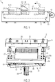
- Fig. 1 shows an exemplary packaging machine 1 in which a work station 3 according to the invention can be used.
- the packaging machine 1 is designed as a thermoforming packaging machine.
- the packaging machine 1 comprises a machine frame 5 on which a forming station 7, a sealing station 9 and a cutting station 11 are arranged.
- the packaging machine 1 comprises a conveying device 13 for conveying a lower film web 15 along a transport direction T.
- the lower film web 15 is successively fed to the forming station 7, an insertion section 17 located between the forming station 7 and the sealing station 9, the sealing station 9 and the cutting station 11.
- packaging troughs are formed in the lower film web 15 by deep drawing.
- the forming station 7 comprises an upper forming tool part 7a and a lower forming tool part 7b which is movable relative thereto and which interact to deep-draw the packaging trays in the lower film web 15.
- the packaging trays formed in the lower film web 15 are filled with products to be packaged.
- the filled packagings are closed in the sealing station 9 by sealing an upper film 19 onto the lower film 15.
- the sealing station 9 comprises an upper sealing tool part 9a and a lower sealing tool part 9b which is movable relative thereto and which cooperate in order to close the packaging trays with the upper film 19.
- the closed packages are released from the film composite.
- the cutting station 11 comprises an upper cutting tool part 11a and a lower cutting tool part 11b movable relative thereto. The upper part 11a of the cutting tool and the lower part 11b of the cutter work together to separate the packaging from the film composite.
- the invention relates to a work station 3 for a packaging machine 1.
- the work station 3 can be, for example, the forming station 7, the sealing station 9 or the cutting station 11 of a deep-drawing packaging machine.
- the work station 3 is used in a packaging machine 1 of a different type, for example in a tray sealing machine.
- the work station 3 comprises an upper tool 21 and a lower tool 23.
- the upper tool 21 in the packaging machine 1 described above are the molding tool upper part 7a, the sealing tool upper part 9a or the cutting tool upper part 11a.
- the lower tool 23 in the packaging machine 1 described above are the molding tool lower part 7b, the sealing tool lower part 9b or the cutting tool lower part 11b.
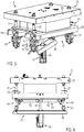
- Fig. 2 shows a schematic perspective view of a workstation 3 according to an embodiment.
- this is a sealing station 9.
- the construction described can, however, also be transferred to other work stations 3 by replacing the upper tool 21 and the lower tool 23 with differently designed tools.
- the upper tool 21 is fixedly attached to the machine frame 5. This can be done using screw holes, for example.
- the upper tool 21 in Fig. 2 may have coolant bores 25.
- Vertical rods 27 are attached to the upper tool 21.
- the vertical rods 27 extend downward from the upper tool 21.
- the rods 27 provide a vertical guide for the lower tool 23.
- the lower tool 23 is guided along a vertical direction for movement towards the upper tool 21.
- the lower tool 23 comprises a working part 23a, which interacts with the upper tool 21 when the lower tool 23 is raised along the vertical direction.
- the working part 23a of the lower tool 23 comprises recesses for at least partially receiving packaging trays.
- the lower tool 23 can first be brought closer to the upper tool 21 along the vertical direction and then pressed against it in order to provide a working pressure. It goes without saying that when the lower tool 23 is pressed against the upper tool 21, one or more components can be present between the lower tool 23 and the upper tool 21.
- the lower film web 15 can be between the lower mold part 7b and the upper mold part 7a, or, in the case of a sealing station 9, the lower film web 15 and the upper film 19 can be present between the lower sealing tool part 9b and the upper sealing tool part 9b.
- the lower tool 23 also comprises a support part 23b, on which the working part 23a is supported.
- the Support part 23b of the lower tool 23 has two parallel, horizontal support elements 29.
- the working part 23a of the lower tool 23 can simply stand on the support part 23b.
- the working part 23a can be firmly connected to the support part 23b, for example by screw connections.
- no articulated connection is provided between the support part 23b and the working part 23a of the lower tool 23.
- the work station 3 comprises a lifting mechanism 31 for lifting the lower tool 23 and for applying the closing force for pressing the lower tool 23 against the upper tool 21.
- the lifting mechanism 31 comprises a first actuator arrangement 33 for applying a first force to lift the lower tool 23.
- the first actuator arrangement 33 comprises a first pneumatic cylinder 35, which is fixed to the two carrier elements 29 of the support part 23b of the lower tool 23 connected intermediate plate 37 engages.
- an extendable end of the first pneumatic cylinder 35 is attached to the intermediate plate 37.
- the first actuator arrangement 33 therefore acts directly on the lower tool 23.
- the lifting mechanism 31 also includes a toggle lever mechanism 41.
- the toggle lever mechanism 41 includes several toggle lever constructions 43.
- the individual toggle lever constructions 43 are designed analogously to one another in the embodiment shown.
- the toggle lever mechanism 41 comprises four toggle lever constructions 43, which are each arranged on one of the vertical rods 27.
- the toggle lever structures 43 each include a first lever 45 and a second lever 47.
- the first lever 45 is connected to the associated rod 27 so as to be rotatable about a horizontal axis.
- the second lever 47 is connected to the lower tool 23 such that it can rotate about a horizontal axis.
- the first lever 45 and the second lever 47 are connected to one another at a connection point 49 such that they can rotate about a horizontal axis.
- the lifting mechanism 31 also comprises a second actuator arrangement 51 which, in the embodiment shown, comprises two second pneumatic cylinders 53.
- the second pneumatic cylinders 53 each connect two opposing toggle lever structures 43. As shown in FIG Fig. 4 and 6th As can be seen, the second pneumatic cylinders 53 are connected to the assigned toggle lever structures 43 in such a way that the toggle lever structures 43 are erected when the second pneumatic cylinders 53 are extended and a force for lifting the lower tool 23 is thus generated. Retraction of the second pneumatic cylinder, that is to say shortening the second pneumatic cylinder 53, on the other hand, can lead to the toggle lever structures 43 collapsing and the lower tool 23 lowering.
- the first actuator arrangement 33 engages, as shown in FIG Fig. 3 can be seen, bypassing the toggle mechanism 41 on the lower tool 23.
- the force acting on the lower tool 23 by the first actuator arrangement 33 therefore does not take place via the toggle lever mechanism 41.
- a translation of the toggle lever mechanism 41 is not relevant for the force transmission through the first actuator arrangement 33 to the lower tool 23.
- the second actuator arrangement 51 acts on the toggle lever mechanism 41.
- a power transmission for lifting the lower tool 23 by the second actuator arrangement 51 takes place in accordance with the translation of the toggle lever mechanism 41.
- the first actuator arrangement 33 is actuated to raise the lower tool 23.
- the first pneumatic cylinder 35 is extended and lifts the lower tool 23.
- the second actuator arrangement 51 is in a freewheeling mode.
- the second pneumatic cylinders 53 can thus be extended or retracted essentially without resistance.
- the toggle lever mechanism 41 By lifting the lower tool 23 by means of the first actuator arrangement 33, which engages the lower tool 23 by bypassing the toggle mechanism 41, the toggle lever mechanism 41 is put into a state in which there is an improved transmission ratio when the toggle lever mechanism 41 is actuated by the second actuator arrangement 51 .
- the second actuator arrangement 51 When the lower tool 23 has been raised by the first actuator arrangement 33 to a certain extent, the second actuator arrangement 51 is activated and acts on the toggle lever mechanism 41 to further raise the lower tool 23 or to press the lower tool 23 against the upper tool 21 by an extension the second pneumatic cylinder 51 and a resulting power transmission by means of the toggle mechanism 41 to the lower tool 23.
- This procedure is particularly efficient because the toggle mechanism 41 has already been brought into a work area with a good ratio by the first actuator arrangement 33 before the second actuator arrangement 51 is activated.
- the first actuator arrangement 33 can essentially be dimensioned in such a way that it applies the force required for lifting the lower tool 23, that is to say can counteract at least the weight of the lower tool 23.
- the additional force for pressing the lower tool 23 against the upper tool 21 can be provided by the second actuator arrangement 51.
- the second pneumatic cylinders 53 of the second actuator arrangement 51 can be made relatively small due to the division of the force between the first actuator arrangement 33 and the second actuator arrangement 51 when the lower tool 23 is pressed against the upper tool 21 and due to the good transmission ratio in the toggle lever mechanism 41.
- the lower tool 23, the first actuator assembly 33 and the second actuator assembly 51 are supported by the vertical rods 27.
- the stroke of the lower tool 23 can be adjusted in a simple manner by adjusting the vertical rods 27 on the upper tool 21.
Landscapes
- Engineering & Computer Science (AREA)
- Mechanical Engineering (AREA)
- Press Drives And Press Lines (AREA)
- Auxiliary Devices For And Details Of Packaging Control (AREA)
- Forklifts And Lifting Vehicles (AREA)
Abstract
Description
- Die vorliegende Erfindung betrifft Arbeitsstationen für Verpackungsmaschinen mit einem Hubwerk zum Anheben eines Unterwerkzeugs.
- Aus der
DE 103 51 567 B4 ist eine als Thermoformer ausgebildete Verpackungsmaschine bekannt, bei der mindestens ein Werkzeug mit einem Kniehebel in eine abgesenkte und in eine angehobene Stellung verschiebbar ist. Das Werkzeug weist als Antrieb einen Elektrolinearantrieb auf, welcher den Kniehebel antreibt. - Die
DE 42 16 210 A1 beschreibt eine Verpackungsmaschine mit einer Tiefziehstation, welche ein Oberteil und ein relativ dazu in eine abgesenkte Stellung senkbares bzw. in eine angehobene Stellung anhebbares Unterteil aufweist. Zum Bewegen des Unterteils ist eine Hubeinrichtung vorgesehen, welche ein Kniehebelsystem umfasst. Das Kniehebelsystem wird über eine Kolben-Zylindereinrichtung betätigt. - Die
DE 10 2009 008 452 B3 beschreibt eine Tiefziehverpackungsmaschine mit einer Arbeitsstation, welche eine ortsfeste Werkzeughälfte und eine bewegbare Werkzeughälfte umfasst. Die ortsfeste Werkzeughälfte ist an oberen Enden von Führungsholmen befestigt. Die bewegbare Werkzeughälfte ist über Führungsbuchsen entlang den Führungsholmen bewegbar und kann daher zu der ortsfesten Werkzeughälfte hin und von dieser weg bewegt werden. Die bewegbare Werkzeughälfte wird durch ein elektrisches Hubwerk zu der ortsfesten Werkzeughälfte hin und von dieser weg bewegt. Das elektrische Hubwerk besteht aus einer ersten Hubvorrichtung zum Bewirken einer Hubbewegung mit großem Hub und einer zweiten Hubvorrichtung zum Bewirken einer Hubbewegung mit kleinem Hub. Die zweite Hubvorrichtung erzeugt eine Kraft, die die bewegbare Werkzeughälfte gegen die ortsfeste Werkzeughälfte drückt. Die erste Hubvorrichtung besteht aus einem ersten Elektromotor und einem Kniehebelgestänge. Die erste Hubvorrichtung bewirkt einen großen Hub der bewegbaren Werkzeughälfte, der dann erreicht ist, wenn ein Totpunkt des Kniehebelgestänges erreicht ist. Die zweite Hubvorrichtung umfasst einen Elektromotor und eine Exzenterwelle, die einen ersten Hebel des Kniehebelgestänges mit einem zweiten Hebel des Kniehebelgestänges verbindet. Wenn die Abtriebswelle des zweiten Elektromotors gedreht wird, wird der zweite Hebel des Kniehebelgestänges relativ zu dem ersten Hebel des Kniehebelgestänges angehoben oder abgesenkt, wodurch ein Hub des zweiten Hebels erzeugt wird. - Es besteht ein Bedarf für ein Hubwerk zum Anheben eines Unterwerkzeugs einer Arbeitsstation einer Verpackungsmaschine, welches eine gute Kraftübertragung aufweist. Es besteht ein Bedarf für ein Hubwerk zum Anheben eines Unterwerkzeugs einer Arbeitsstation einer Verpackungsmaschine, welches kostengünstig herstellbar ist. Es besteht ein Bedarf für ein Hubwerk zum Anheben eines Unterwerkzeugs einer Arbeitsstation einer Verpackungsmaschine, welches eine große Stabilität aufweist.
- Die Erfindung betrifft eine Arbeitsstation für eine Verpackungsmaschine gemäß Anspruch 1 und ein Verfahren zum Betreiben einer Arbeitsstation für eine Verpackungsmaschine gemäß Anspruch 12. Die abhängigen Ansprüche geben vorteilhafte Ausführungsformen der Erfindung an.
- Eine erfindungsgemäße Arbeitsstation für eine Verpackungsmaschine umfasst ein Oberwerkzeug, ein Unterwerkzeug und ein Hubwerk. Das Unterwerkzeug ist für eine entlang einer vertikalen Richtung zu dem Oberwerkzeug hin gerichtete Schließbewegung geführt. Das Hubwerk umfasst einen Kniehebelmechanismus, welcher das Unterwerkzeug und eine Stützstruktur miteinander verbindet. Das Hubwerk weist eine erste Aktuatoranordnung und eine zweite Aktuatoranordnung auf. Die erste Aktuatoranordnung ist zum Aufbringen einer ersten Kraft zum Anheben des Unterwerkzeugs konfiguriert. Die zweite Aktuatoranordnung ist zum Aufbringen einer zweiten Kraft zum Anheben des Unterwerkzeugs konfiguriert. Die erste Aktuatoranordnung greift unter Umgehung des Kniehebelmechanismus an dem Unterwerkzeug an. Die zweite Aktuatoranordnung greift an dem Kniehebelmechanismus an.
- Im Sinne der Erfindung sind sowohl Kräfte, die tatsächlich zum Anheben des Unterwerkzeugs führen, als auch Kräfte, die das Unterwerkzeug nach oben hin beaufschlagen, aber nicht zu einer tatsächlichen Bewegung des Unterwerkzeugs führen, Kräfte "zum Anheben des Unterwerkzeugs". Insbesondere ist eine Anpresskraft, mit der das Unterwerkzeug von unten an das Oberwerkzeug gepresst wird, im Sinne der Erfindung eine "Kraft zum Anheben des Unterwerkzeugs" oder Teil einer solchen.
- Dadurch, dass zwei Aktuatoranordnungen zum Aufbringen von Kräften zum Anheben des Unterwerkzeugs vorgesehen sind, können die einzelnen Aktuatoranordnungen kleiner dimensioniert werden, als wenn nur eine einzige Aktuatoranordnung vorgesehen wäre. Ein geeignetes Anpassen der auf das Unterwerkzeug wirkenden Hubkräfte abhängig von der Betriebssituation der Arbeitsstation wird vereinfacht. Beispielsweise kann in bestimmten Betriebszuständen nur eine der beiden Aktuatoranordnungen aktiv sein, um eine Kraft auf das Unterwerkzeug auszuüben, während die andere Aktuatoranordnung inaktiv ist. In Betriebszuständen, bei denen eine erhöhte Kraft zum Anheben des Unterwerkzeugs erforderlich ist, insbesondere wenn das Unterwerkzeug an das Oberwerkzeug gepresst werden soll, können beide Aktuatoranordnungen aktiv sein.
- Ein Kniehebelmechanismus hat die Eigenschaft, dass sich das Übersetzungsverhältnis zwischen aufgewendeter Kraft und resultierender Kraft während der Bewegung des Kniehebelmechanismus kontinuierlich verschiebt. Der Kniehebelmechanismus hat also Bewegungsbereiche, in denen er ein für eine große Kraftübertragung günstiges Übersetzungsverhältnis bereitstellt, aber auch Bewegungsbereiche, in denen das Übersetzungsverhältnis für eine hohe Kraftübertragung ungünstig ist. Dadurch, dass die erste Aktuatoranordnung unter Umgehung des Kniehebelmechanismus an dem Unterwerkzeug angreift, ist die Wirkung der von der ersten Aktuatoranordnung aufgebrachten ersten Kraft auf das Unterwerkzeug unabhängig von dem momentanen Betriebszustand des Kniehebelmechanismus. Hierdurch kann gewährleistet werden, dass sich das Unterwerkzeug auch dann effizient anheben lässt, wenn der Kniehebelmechanismus in einem Zustand vorliegt, in dem er ein für eine gute Kraftübertragung ungünstiges Übersetzungsverhältnis aufweist. Die zweite Aktuatoranordnung greift an dem Kniehebelmechanismus an und erlaubt ein Ausnutzen der durch den Kniehebelmechanismus bereitgestellten Hebelwirkung zum Anheben des Unterwerkzeugs.
- Die erste Aktuatoranordnung kann direkt an dem Unterwerkzeug angreifen. Die erste Aktuatoranordnung kann an einem starr mit dem Unterwerkzeug verbundenen Element angreifen. Die erste Aktuatoranordnung kann an einem Element angreifen, welches das Unterwerkzeug trägt, ohne dass eine gelenkige Verbindung zwischen dem Unterwerkzeug und dem Element, an dem die erste Aktuatoranordnung angreift, vorliegt. Die erste Aktuatoranordnung kann ohne Zwischenschalten einer gelenkigen Verbindung an dem Unterwerkzeug angreifen. Es ist auch denkbar, dass beispielsweise maximal eine gelenkige Verbindung zwischen dem Unterwerkzeug und der Aktuatoranordnung vorliegt.
- Mittels der ersten Kraft kann das Unterwerkzeug gegenüber der Stützstruktur angehoben werden. Mittels der ersten Kraft kann das Unterwerkzeug in Bezug auf das Oberwerkzeug angehoben werden. Mittels der zweiten Kraft kann das Unterwerkzeug gegenüber der Stützstruktur angehoben werden. Mittels der zweiten Kraft kann das Unterwerkzeug in Bezug auf das Oberwerkzeug angehoben werden.
- Das Oberwerkzeug kann ortsfest an einem Gestell der Arbeitsstation angebracht sein. Die Stützstruktur kann ortsfest an einem Gestell der Arbeitsstation angebracht oder Teil des Gestells der Arbeitsstation sein. Die Stützstruktur kann bezüglich des Oberwerkzeugs ortsfest sein.
- Die erste Aktuatoranordnung kann dazu konfiguriert sein, das Unterwerkzeug um einen ersten Hub anzuheben. Die zweite Aktuatoranordnung kann dazu konfiguriert sein, das Unterwerkzeug um einen zweiten Hub anzuheben. Der erste Hub kann größer als der zweite Hub sein. Die erste Aktuatoranordnung kann für das Bereitstellen eines großen Hubs optimiert sein und die zweite Aktuatoranordnung kann für das Bereitstellen einer hohen Kraft zum Anheben des Unterwerkzeugs optimiert sein. Der größere erste Hub der ersten Aktuatoranordnung kann es ermöglichen, das Unterwerkzeug mittels der ersten Aktuatoranordnung bereits relativ nahe an das Oberwerkzeug zu fahren.
- Die zweite Aktuatoranordnung kann dazu konfiguriert sein, zum Aufbringen der zweiten Kraft aktiviert zu werden, nachdem das Unterwerkzeug von der ersten Aktuatoranordnung angehoben wurde. Durch Zuschalten der zweiten Aktuatoranordnung kann nach einem Anheben des Unterwerkzeugs durch die erste Aktuatoranordnung eine erhöhte Kraft für ein Anpressen des Unterwerkzeugs an das Oberwerkzeug bereitgestellt werden.
- Die erste Aktuatoranordnung und die zweite Aktuatoranordnung können dazu konfiguriert sein, die erste Kraft und die zweite Kraft zumindest zeitweise gleichzeitig aufzubringen. Hierdurch kann zeitweise eine besonders hohe Kraft zum Anheben des Unterwerkzeugs bereitgestellt werden. Insbesondere kann eine hohe Kraft zum Anpressen des Unterwerkzeugs an das Oberwerkzeug erzielt werden.
- Vorzugsweise führt ein Anheben des Unterwerkzeugs durch die erste Aktuatoranordnung auch ohne aktiven Betrieb der zweiten Aktuatoranordnung zu einem Verstellen des Kniehebelmechanismus. Wenn beim Anheben des Unterwerkzeugs durch die erste Aktuatoranordnung der Kniehebelmechanismus verstellt wird, verändert sich die Übersetzung des Kniehebelmechanismus. Das Vorliegen des ungünstigen Übersetzungsbereichs des Kniehebelmechanismus wirkt sich beim Anheben des Unterwerkzeugs durch die erste Aktuatoranordnung nicht negativ aus, da die erste Aktuatoranordnung unter Umgehung des Kniehebelmechanismus an dem Unterwerkzeug angreift. Insbesondere kann während des Anhebens des Unterwerkzeugs durch die erste Aktuatoranordnung ein ungünstiger Übersetzungsbereich des Kniehebelmechanismus überwunden werden.
- Vorzugsweise hat ein Anheben des Hubwerks durch die erste Aktuatoranordnung ein Strecken des Kniehebelmechanismus zur Folge. Beim Strecken des Kniehebelmechanismus kann die Übersetzung für die zweite Kraft zum Anheben des Unterwerkzeugs durch die zweite Aktuatoranordnung vergrößert werden.
- Die zweite Aktuatoranordnung kann dazu konfiguriert sein, eine Anpresskraft zum Anpressen des Unterwerkzeugs an das Oberwerkzeug bereitzustellen.
- Prinzipiell kann es ausreichend sein, wenn der Kniehebelmechanismus eine einzige Kniehebelkonstruktion umfasst, die das Unterwerkzeug und die Stützstruktur miteinander verbindet. Vorzugsweise umfasst der Kniehebelmechanismus jedoch mehrere Kniehebelkonstruktionen, die jeweils das Unterwerkzeug und die Stützstruktur miteinander verbinden. Durch das Vorsehen mehrerer Kniehebelkonstruktionen kann eine verbesserte Kraftaufnahme durch das Unterwerkzeug gewährleistet sein. Zudem kann sich das Vorsehen mehrerer Kniehebelkonstruktionen verbessernd auf die Stabilität des Unterwerkzeugs auswirken. Die zweite Aktuatoranordnung greift vorzugsweise an den mehreren Kniehebelkonstruktionen an.
- Die zweite Aktuatoranordnung kann ein längenveränderliches Element umfassen. Das längenveränderliche Element kann gleichzeitig an zwei gegenüberliegenden Kniehebelkonstruktionen angreifen. Durch das Angreifen des längenveränderlichen Elements an zwei gegenüberliegenden Kniehebelkonstruktionen lässt sich eine verbesserte Krafteinleitung in die Kniehebelkonstruktionen erreichen. Das längenveränderliche Element kann beispielsweise einen Pneumatikzylinder, einen Spindeltrieb oder einen Elektrolinearantrieb umfassen.
- Die erste Aktuatoranordnung und/oder die zweite Aktuatoranordnung kann ein längenveränderliches Element aufweisen. Hierbei kann es sich beispielsweise um einen Pneumatikzylinder, einen Spindeltrieb oder einen Elektrolinearantrieb handeln.
- Das Unterwerkzeug kann an Stangen aufgehängt sein. Die Stangen können beispielsweise fest mit dem Oberwerkzeug verbunden sein. Die erste Aktuatoranordnung kann an den Stangen aufgehängt sein. Die zweite Aktuatoranordnung kann an den Stangen aufgehängt sein.
- Die zweite Aktuatoranordnung kann derart an dem Kniehebelmechanismus angreifen, dass eine Übersetzung der von der zweiten Aktuatoranordnung aufgebrachten zweiten Kraft durch den Kniehebelmechanismus eine größere Wirkung zum Anheben des Unterwerkzeugs entfaltet je weiter der Kniehebelmechanismus gestreckt ist.
- Die Erfindung betrifft auch ein Verfahren zum Betreiben einer Arbeitsstation für eine Verpackungsmaschine. Das Verfahren kann zum Betreiben der erfindungsgemäßen Arbeitsstation geeignet, ausgelegt und/oder konfiguriert sein. Im Hinblick auf die Arbeitsstation beschriebene Merkmale lassen sich auf das Verfahren übertragen und umgekehrt.
- Ein erfindungsgemäßes Verfahren zum Betreiben einer Arbeitsstation für eine Verpackungsmaschine umfasst das Anheben eines Unterwerkzeugs entlang einer vertikalen Richtung auf ein Oberwerkzeug zu durch Aufbringen einer ersten Kraft mittels einer ersten Aktuatoranordnung. Die erste Aktuatoranordnung greift unter Umgehung eines Kniehebelmechanismus an dem Unterwerkzeug an, wobei der Kniehebelmechanismus das Unterwerkzeug und eine Stützstruktur miteinander verbindet. Das Verfahren umfasst zudem das Aufbringen einer zweiten Kraft zum Anpressen des Unterwerkzeugs an das Oberwerkzeug mittels einer zweiten Aktuatoranordnung. Die zweite Aktuatoranordnung greift an der Kniehebelanordnung an.
- Durch das Anheben des Unterwerkzeugs mittels der ersten Aktuatoranordnung wird vorzugsweise die Kniehebelanordnung verstellt.
- Vorzugsweise wird die Kniehebelanordnung zunächst durch Anheben des Unterwerkzeugs mittels der ersten Aktuatoranordnung in einen Arbeitsbereich mit verbesserter Hebelwirkung (verbesserter Übersetzung) verstellt. Anschließend betätigt die zweite Aktuatoranordnung aktiv die Kniehebelanordnung zum weiteren Anheben des Unterwerkzeugs und/oder zum Anpressen des Unterwerkzeugs an das Oberwerkzeug.
- Während des Aufbringens der zweiten Kraft kann zumindest temporär auch die erste Kraft aufgebracht werden.
- Im Folgenden wird die Erfindung anhand von Ausführungsbeispielen weiter erläutert. Es zeigt
- Figur 1
- eine schematische Seitenansicht einer Verpackungsmaschine mit einer Arbeitsstation gemäß einer Ausführungsform;
- Figur 2
- eine schematische Perspektivansicht einer Arbeitsstation gemäß einer Ausführungsform im geöffneten Zustand der Arbeitsstation;
- Figur 3
- eine weitere schematische Perspektivansicht der Arbeitsstation im geöffneten Zustand der Arbeitsstation;
- Figur 4
- eine schematische Seitenansicht der Arbeitsstation im geöffneten Zustand der Arbeitsstation;
- Figur 5
- eine schematische Perspektivansicht der Arbeitsstation im geschlossenen Zustand der Arbeitsstation; und
- Figur 6
- eine schematische Seitenansicht der Arbeitsstation im geschlossenen Zustand der Arbeitsstation.
-
Fig. 1 zeigt eine beispielhafte Verpackungsmaschine 1, in der eine erfindungsgemäße Arbeitsstation 3 einsetzbar ist. In der gezeigten Ausführungsform ist die Verpackungsmaschine 1 als Tiefziehverpackungsmaschine ausgebildet. Die Verpackungsmaschine 1 umfasst einen Maschinenrahmen 5, an welchem eine Formstation 7, eine Siegelstation 9 und eine Schneidstation 11 angeordnet sind. Die Verpackungsmaschine 1 umfasst eine Fördereinrichtung 13 zum Fördern einer Unterfolienbahn 15 entlang einer Transportrichtung T. Die Unterfolienbahn 15 wird nacheinander der Formstation 7, einer zwischen der Formstation 7 und der Siegelstation 9 liegenden Einlegestrecke 17, der Siegelstation 9 und der Schneidstation 11 zugeführt. - In der Formstation 7 werden durch Tiefziehen Verpackungsmulden in der Unterfolienbahn 15 ausgeformt. Die Formstation 7 umfasst ein Formwerkzeugoberteil 7a und ein relativ dazu bewegliches Formwerkzeugunterteil 7b, welche zum Tiefziehen der Verpackungsmulden in der Unterfolienbahn 15 zusammenwirken. In der Einlegestrecke 17 werden die in der Unterfolienbahn 15 ausgeformten Verpackungsmulden mit zu verpackenden Produkten befüllt. Die befüllten Verpackungen werden in der Siegelstation 9 durch Ansiegeln einer Oberfolie 19 an die Unterfolie 15 verschlossen. Die Siegelstation 9 umfasst ein Siegelwerkzeugoberteil 9a und ein relativ dazu bewegliches Siegelwerkzeugunterteil 9b, welche zusammenwirken, um die Verpackungsmulden mit der Oberfolie 19 zu verschließen. In der Schneidstation 11 werden die verschlossenen Verpackungen aus dem Folienverbund gelöst. Die Schneidstation 11 umfasst ein Schneidwerkzeugoberteil 11a und ein relativ dazu beweglichen Schneidwerkzeugunterteil 11b. Das Schneidwerkzeugoberteil 11a und das Schneidwerkunterteil 11b wirken zum Austrennen der Verpackungen aus dem Folienverbund zusammen.
- Die Erfindung betrifft eine Arbeitsstation 3 für eine Verpackungsmaschine 1. Bei der Arbeitsstation 3 kann es sich beispielsweise um die Formstation 7, die Siegelstation 9 oder die Schneidstation 11 einer Tiefziehverpackungsmaschine handeln. Es wäre aber auch denkbar, dass die Arbeitsstation 3 in einer Verpackungsmaschine 1 eines anderen Typs eingesetzt wird, beispielsweise in einer Schalenverschließmaschine.
- Die Arbeitsstation 3 umfasst ein Oberwerkzeug 21 und ein Unterwerkzeug 23. Beispiele für das Oberwerkzeug 21 sind in der oben beschriebenen Verpackungsmaschine 1 das Formwerkzeugoberteil 7a, das Siegelwerkzeugoberteil 9a oder das Schneidwerkzeugoberteil 11a. Beispiele für das Unterwerkzeug 23 sind in der oben beschriebenen Verpackungsmaschine 1 das Formwerkzeugunterteil 7b, das Siegelwerkzeugunterteil 9b oder das Schneidwerkzeugunterteil 11b.
-
Fig. 2 zeigt in schematischer Perspektivansicht eine Arbeitsstation 3 gemäß einer Ausführungsform. In der gezeigten Variante handelt es sich hierbei um eine Siegelstation 9. Die beschriebene Konstruktion lässt sich aber unter Ersetzen des Oberwerkzeugs 21 und des Unterwerkzeugs 23 durch anders ausgestaltete Werkzeuge auch auf andere Arbeitsstationen 3 übertragen. - In der dargestellten Ausführungsform wird das Oberwerkzeug 21 ortsfest an dem Maschinenrahmen 5 angebracht. Dies kann beispielsweise über Schraublöcher erfolgen. Das Oberwerkzeug 21 in
Fig. 2 kann Kühlmittelbohrungen 25 aufweisen. An dem Oberwerkzeug 21 sind vertikale Stangen 27 angebracht. Die vertikalen Stangen 27 erstrecken sich von dem Oberwerkzeug 21 nach unten. Die Stangen 27 stellen eine vertikale Führung für das Unterwerkzeug 23 bereit. Entlang der Stangen 27 ist das Unterwerkzeug 23 entlang einer vertikalen Richtung für eine Bewegung zu dem Oberwerkzeug 21 hin geführt. In der dargestellten Ausführungsform umfasst das Unterwerkzeug 23 einen Arbeitsteil 23a, welcher bei einem Anheben des Unterwerkzeugs 23 entlang der vertikalen Richtung mit dem Oberwerkzeug 21 zusammenwirkt. In der dargestellten Ausführungsform umfasst der Arbeitsteil 23a des Unterwerkzeugs 23 Ausnehmungen zum zumindest teilweisen Aufnehmen von Verpackungsmulden. In einem Arbeitstakt kann das Unterwerkzeug 23 entlang der vertikalen Richtung zunächst an das Oberwerkzeug 21 angenähert und dann an dieses gepresst werden, um einen Arbeitsdruck bereitzustellen. Es versteht sich, dass beim Anpressen des Unterwerkzeugs 23 an das Oberwerkzeug 21 eine oder mehrere Komponenten zwischen dem Unterwerkzeug 23 und dem Oberwerkzeug 21 vorliegen können. Beispielsweise kann im Falle einer Formstation 7 die Unterfolienbahn 15 zwischen dem Formwerkzeugunterteil 7b und dem Formwerkzeugoberteil 7a vorliegen, oder, im Falle einer Siegelstation 9, die Unterfolienbahn 15 und die Oberfolie 19 zwischen dem Siegelwerkzeugunterteil 9b und dem Siegelwerkzeugoberteil 9b vorliegen. - In der dargestellten Ausführungsform umfasst das Unterwerkzeug 23 zudem einen Stützteil 23b, auf dem sich der Arbeitsteil 23a abstützt. In der gezeigten Ausführungsform umfasst der Stützteil 23b des Unterwerkzeugs 23 zwei parallele, horizontale Trägerelemente 29. Der Arbeitsteil 23a des Unterwerkzeugs 23 kann einfach auf dem Stützteil 23b stehen. Optional kann der Arbeitsteil 23a fest mit dem Stützteil 23b verbunden sein, beispielsweise durch Schraubverbindungen. Vorzugsweise ist zwischen dem Stützteil 23b und dem Arbeitsteil 23a des Unterwerkzeugs 23 keine gelenkige Verbindung vorgesehen.
- Die Arbeitsstation 3 umfasst ein Hubwerk 31 zum Anheben des Unterwerkzeugs 23 und zum Aufbringen der Schließkraft für das Anpressen des Unterwerkzeugs 23 an das Oberwerkzeug 21. Wie wohl am Besten aus
Fig. 3 ersichtlich, umfasst das Hubwerk 31 eine erste Aktuatoranordnung 33 zum Aufbringen einer ersten Kraft zum Anheben des Unterwerkzeugs 23. Die erste Aktuatoranordnung 33 umfasst in der dargestellten Ausführungsform einen ersten Pneumatikzylinder 35, der an einer fest mit den beiden Trägerelementen 29 des Stützteils 23b des Unterwerkzeugs 23 verbundenen Zwischenplatte 37 angreift. In der gezeigten Ausführungsform ist ein ausfahrbares Ende des ersten Pneumatikzylinders 35 an der Zwischenplatte 37 befestigt. Die erste Aktuatoranordnung 33 greift in der gezeigten Ausführungsform also direkt an dem Unterwerkzeug 23 an. In bestimmten Ausführungsformen wäre es auch denkbar, dass zwischen dem Unterwerkzeug 23 und dem ersten Pneumatikzylinder 35 weitere Verbindungselemente zwischengeschaltet sind. Ein stationärer Teil des ersten Pneumatikzylinders 35 ist an einem Verbindungsträger 39 befestigt, welcher an zwei gegenüberliegenden der vertikalen Stangen 27 befestigt ist. Die erste Aktuatoranordnung 33 ist somit mittels der vertikalen Stangen 27 an dem Oberwerkzeug 21 aufgehängt. - Wie wohl am Besten aus den
Fig. 5 und 6 ersichtlich, welche die Arbeitsstation 3 in einer geschlossenen Stellung, also mit angehobenem Unterwerkzeug 23, zeigen, umfasst das Hubwerk 31 zudem einen Kniehebelmechanismus 41. Der Kniehebelmechanismus 41 umfasst mehrere Kniehebelkonstruktionen 43. Die einzelnen Kniehebelkonstruktionen 43 sind in der dargestellten Ausführungsform analog zueinander ausgebildet. In der dargestellten Ausführungsform umfasst der Kniehebelmechanismus 41 vier Kniehebelkonstruktionen 43, die jeweils an einer der vertikalen Stangen 27 angeordnet sind. Die Kniehebelkonstruktionen 43 umfassen jeweils einen ersten Hebel 45 und einen zweiten Hebel 47. Der erste Hebel 45 ist um eine horizontale Achse drehbar mit der zugeordneten Stange 27 verbunden. Der zweite Hebel 47 ist um eine horizontale Achse drehbar mit dem Unterwerkzeug 23 verbunden. Zudem sind der erste Hebel 45 und der zweite Hebel 47 an einer Verbindungsstelle 49 um eine horizontale Achse drehbar miteinander verbunden. - Das Hubwerk 31 umfasst noch eine zweite Aktuatoranordnung 51, welche in der gezeigten Ausführungsform zwei zweite Pneumatikzylinder 53 umfasst. Die zweiten Pneumatikzylinder 53 verbinden jeweils zwei einander gegenüberliegende Kniehebelkonstruktionen 43. Wie anhand der
Fig. 4 und6 ersichtlich, sind die zweiten Pneumatikzylinder 53 derart mit den zugeordneten Kniehebelkonstruktionen 43 verbunden, dass die Kniehebelkonstruktionen 43 bei einem Ausfahren der zweiten Pneumatikzylinder 53 aufgerichtet werden und somit eine Kraft zum Anheben des Unterwerkzeugs 23 erzeugt wird. Ein Einfahren der zweiten Pneumatikzylinder, also eine Verkürzung der zweiten Pneumatikzylinder 53, kann dagegen zu einem Zusammenklappen der Kniehebelkonstruktionen 43 und einem Absenken des Unterwerkzeugs 23 führen. - Die erste Aktuatoranordnung 33 greift, wie anhand von
Fig. 3 ersichtlich, unter Umgehung des Kniehebelmechanismus 41 an dem Unterwerkzeug 23 an. Die Krafteinwirkung auf das Unterwerkzeug 23 durch die erste Aktuatoranordnung 33 erfolgt also nicht über den Kniehebelmechanismus 41. Eine Übersetzung des Kniehebelmechanismus 41 ist für die Kraftübertragung durch die erste Aktuatoranordnung 33 auf das Unterwerkzeug 23 nicht relevant. Die zweite Aktuatoranordnung 51 dagegen greift an dem Kniehebelmechanismus 41 an. Eine Kraftübertragung zum Anheben des Unterwerkzeugs 23 durch die zweite Aktuatoranordnung 51 erfolgt gemäß der Übersetzung des Kniehebelmechanismus 41. - Soll das Unterwerkzeug 23 aus der in den
Fig. 2 ,3 und 4 gezeigten abgesenkten Position (offene Arbeitsstation 3) angehoben werden, wird zunächst die erste Aktuatoranordnung 33 zum Anheben des Unterwerkzeugs 23 betätigt. Der erste Pneumatikzylinder 35 wird ausgefahren und hebt das Unterwerkzeug 23 an. In dieser Phase befindet sich die zweite Aktuatoranordnung 51 in einem Freilaufmodus. Die zweiten Pneumatikzylinder 53 können also im Wesentlichen ohne Widerstand ein-oder ausgefahren werden. Beim Anheben des Unterwerkzeugs 23 durch die erste Aktuatoranordnung 33 wird, gewissermaßen als positiver Nebeneffekt, der Kniehebelmechanismus 41 zu einem gewissen Grad aufgerichtet. Der Kniehebelmechanismus 41 wird also durch das Anheben des Unterwerkzeugs 23 mittels der ersten Aktuatoranordnung 33, die unter Umgehung des Kniehebelmechanismus 41 an dem Unterwerkzeug 23 angreift, in einen Zustand versetzt, in dem eine verbesserte Übersetzung beim Betätigen des Kniehebelmechanismus 41 durch die zweite Aktuatoranordnung 51 vorliegt. Wenn das Unterwerkzeug 23 bis zu einem gewissen Grad von der ersten Aktuatoranordnung 33 angehoben wurde, wird die zweite Aktuatoranordnung 51 aktiv geschaltet und wirkt auf den Kniehebelmechanismus 41 zum weiteren Anheben des Unterwerkzeugs 23 oder zum Anpressen des Unterwerkzeugs 23 an das Oberwerkzeug 21. Konkret erfolgt dies durch ein Ausfahren der zweiten Pneumatikzylinder 51 und eine daraus resultierende Kraftübertragung mittels des Kniehebelmechanismus 41 auf das Unterwerkzeug 23. Dieses Vorgehen ist besonders effizient, da der Kniehebelmechanismus 41 vor Aktivieren der zweiten Aktuatoranordnung 51 bereits durch die erste Aktuatoranordnung 33 in einen Arbeitsbereich mit einer guten Übersetzung verbracht wurde. - Die erste Aktuatoranordnung 33 kann im Wesentlichen so dimensioniert sein, dass sie die für das Anheben des Unterwerkzeugs 23 erforderliche Kraft aufbringt, also zumindest der Gewichtskraft des Unterwerkzeugs 23 entgegenwirken kann. Die zusätzliche Kraft für das Anpressen des Unterwerkzeugs 23 an das Oberwerkzeug 21 kann durch die zweite Aktuatoranordnung 51 bereitgestellt werden. Die zweiten Pneumatikzylinder 53 der zweiten Aktuatoranordnung 51 können aufgrund der Aufteilung der Kraft zwischen der ersten Aktuatoranordnung 33 und der zweiten Aktuatoranordnung 51 beim Anpressen des Unterwerkzeugs 23 an das Oberwerkzeug 21 und aufgrund des guten Übersetzungsverhältnisses in dem Kniehebelmechanismus 41 relativ klein dimensioniert werden.
- Das Unterwerkzeug 23, die erste Aktuatoranordnung 33 und die zweite Aktuatoranordnung 51 werden von den vertikalen Stangen 27 getragen. Eine Einstellung des Hubs des Unterwerkzeugs 23 kann auf einfache Art und Weise durch ein Verstellen der vertikalen Stangen 27 an dem Oberwerkzeug 21 erfolgen.
Claims (15)
- Arbeitsstation (3) für eine Verpackungsmaschine (1), umfassend
ein Oberwerkzeug (21) und ein Unterwerkzeug (23), wobei das Unterwerkzeug (23) für eine entlang einer vertikalen Richtung zu dem Oberwerkzeug (21) hin gerichtete Schließbewegung geführt ist; und
ein Hubwerk (31), welches einen Kniehebelmechanismus (41) umfasst, der das Unterwerkzeug (23) und eine Stützstruktur miteinander verbindet,
wobei das Hubwerk (31) eine erste Aktuatoranordnung (33), die zum Aufbringen einer ersten Kraft zum Anheben des Unterwerkzeugs (23) konfiguriert ist, und eine zweite Aktuatoranordnung (51) umfasst, die zum Aufbringen einer zweiten Kraft zum Anheben des Unterwerkzeugs (23) konfiguriert ist, und
wobei die erste Aktuatoranordnung (33) unter Umgehung des Kniehebelmechanismus (41) an dem Unterwerkzeug (23) angreift und die zweite Aktuatoranordnung (51) an dem Kniehebelmechanismus (41) angreift. - Arbeitsstation nach Anspruch 1, wobei die erste Aktuatoranordnung (33) dazu konfiguriert ist, das Unterwerkzeug (23) um einen ersten Hub anzuheben, und die zweite Aktuatoranordnung (51) dazu konfiguriert ist, das Unterwerkzeug (23) um einen zweiten Hub anzuheben, wobei der erste Hub größer als der zweite Hub ist.
- Arbeitsstation nach Anspruch 1 oder 2, wobei die zweite Aktuatoranordnung (51) dazu konfiguriert ist, zum Aufbringen der zweiten Kraft aktiviert zu werden, nachdem das Unterwerkzeug (23) von der ersten Aktuatoranordnung (33) angehoben wurde.
- Arbeitsstation nach einem der vorangehenden Ansprüche, wobei die erste Aktuatoranordnung (33) und die zweite Aktuatoranordnung (51) dazu konfiguriert sind, die erste Kraft und die zweite Kraft zumindest zeitweise gleichzeitig aufzubringen.
- Arbeitsstation nach einem der vorangehenden Ansprüche, wobei ein Anheben des Unterwerkzeugs (23) durch die erste Aktuatoranordnung (33) auch ohne aktiven Betrieb der zweiten Aktuatoranordnung (51) zu einem Verstellen des Kniehebelmechanismus (41) führt.
- Arbeitsstation nach einem der vorangehenden Ansprüche, wobei ein Anheben des Unterwerkzeugs (23) durch die erste Aktuatoranordnung (33) ein Strecken des Kniehebelmechanismus (41) zur Folge hat.
- Arbeitsstation nach einem der vorangehenden Ansprüche, wobei die zweite Aktuatoranordnung (51) dazu konfiguriert ist, eine Anpresskraft zum Anpressen des Unterwerkzeugs (23) an das Oberwerkzeug (21) bereitzustellen.
- Arbeitsstation nach einem der vorangehenden Ansprüche, wobei der Kniehebelmechanismus (41) mehrere Kniehebelkonstruktionen (43) umfasst, die jeweils das Unterwerkzeug (23) und die Stützstruktur miteinander verbinden, wobei die zweite Aktuatoranordnung (51) vorzugsweise an den mehreren Kniehebelkonstruktionen (43) angreift.
- Arbeitsstation nach Anspruch 8, wobei die zweite Aktuatoranordnung (51) ein längenveränderliches Element, insbesondere einen Pneumatikzylinder (53), umfasst, das gleichzeitig an zwei gegenüberliegenden Kniehebelkonstruktionen (43) angreift.
- Arbeitsstation nach einem der vorangehenden Ansprüche, wobei die erste Aktuatoranordnung (33) und/oder die zweite Aktuatoranordnung (51) ein längenveränderliches Element umfasst, insbesondere einen Pneumatikzylinder (35, 53).
- Arbeitsstation nach einem der vorangehenden Ansprüche, wobei das Unterwerkzeug (23) an Stangen (27) aufgehängt ist, wobei vorzugsweise auch die erste und/oder die zweite Aktuatoranordnung (33, 51) an den Stangen (27) aufgehängt ist.
- Verfahren zum Betreiben einer Arbeitsstation (3) für eine Verpackungsmaschine (1), umfassend
Anheben eines Unterwerkzeugs (23) entlang einer vertikalen Richtung auf ein Oberwerkzeug (21) zu durch Aufbringen einer ersten Kraft mittels einer ersten Aktuatoranordnung (33), welche unter Umgehung eines Kniehebelmechanismus (41), welcher das Unterwerkzeug (23) und eine Stützstruktur miteinander verbindet, an dem Unterwerkzeug (23) angreift;
Aufbringen einer zweiten Kraft zum Anpressen des Unterwerkzeugs (23) an das Oberwerkzeug (21) mittels einer zweiten Aktuatoranordnung (51), welche an der Kniehebelanordnung (41) angreift. - Verfahren nach Anspruch 12, wobei durch das Anheben des Unterwerkzeugs (23) mittels der ersten Aktuatoranordnung (33) die Kniehebelanordnung (41) verstellt wird.
- Verfahren nach Anspruch 12 oder 13, wobei die Kniehebelanordnung (41) zunächst durch Anheben des Unterwerkzeugs (23) mittels der ersten Aktuatoranordnung (33) in einen Arbeitsbereich mit verbesserter Hebelwirkung verstellt wird und dann die zweite Aktuatoranordnung (51) zum weiteren Anheben des Unterwerkzeugs (23) und/oder zum Anpressen des Unterwerkzeugs (23) an das Oberwerkzeug (21) die Kniehebelanordnung (41) aktiv betätigt
- Verfahren nach einem der Ansprüche 12 bis 14, wobei während des Aufbringens der zweiten Kraft zumindest temporär auch die erste Kraft aufgebracht wird.
Applications Claiming Priority (1)
| Application Number | Priority Date | Filing Date | Title |
|---|---|---|---|
| DE102019219833.3A DE102019219833A1 (de) | 2019-12-17 | 2019-12-17 | Arbeitsstation für eine Verpackungsmaschine mit einem Hubwerk mit Kniehebelmechanismus |
Publications (2)
| Publication Number | Publication Date |
|---|---|
| EP3838769A1 true EP3838769A1 (de) | 2021-06-23 |
| EP3838769B1 EP3838769B1 (de) | 2022-12-28 |
Family
ID=73598780
Family Applications (1)
| Application Number | Title | Priority Date | Filing Date |
|---|---|---|---|
| EP20210091.3A Active EP3838769B1 (de) | 2019-12-17 | 2020-11-26 | Arbeitsstation für eine verpackungsmaschine mit einem hubwerk mit kniehebelmechanismus |
Country Status (5)
| Country | Link |
|---|---|
| US (1) | US11713152B2 (de) |
| EP (1) | EP3838769B1 (de) |
| CN (1) | CN214649364U (de) |
| DE (1) | DE102019219833A1 (de) |
| ES (1) | ES2936655T3 (de) |
Families Citing this family (1)
| Publication number | Priority date | Publication date | Assignee | Title |
|---|---|---|---|---|
| DE102020134816A1 (de) * | 2020-12-23 | 2022-06-23 | Multivac Sepp Haggenmüller Se & Co. Kg | Hubwerk |
Citations (6)
| Publication number | Priority date | Publication date | Assignee | Title |
|---|---|---|---|---|
| EP0569937A1 (de) * | 1992-05-15 | 1993-11-18 | Multivac Sepp Haggenmüller Kg | Arbeitsstation einer Verpackungsmaschine mit bewegbarem Unterteil |
| EP0895933A1 (de) * | 1997-08-08 | 1999-02-10 | Multivac Sepp Haggenmüller Kg | Hubeinrichtung für eine Arbeitsstation einer Verpackungsmaschine |
| WO2005075291A2 (de) * | 2004-02-06 | 2005-08-18 | Cfs Germany Gmbh | Verpackungsmaschine mit mehreren hubvorrichtungen pro arbeitsstation |
| DE102009008452B3 (de) | 2009-02-11 | 2010-10-07 | Multivac Sepp Haggenmüller Gmbh & Co. Kg | Verpackungsmaschine mit einer Arbeitsstation, die ein elektrisches Hubwerk mit Grob- und Feinhub aufweist |
| DE102009017871A1 (de) * | 2009-04-17 | 2010-10-28 | Schuler Pressen Gmbh & Co. Kg | Auswerfereinrichtung für Umformeinrichtung |
| DE10351567B4 (de) | 2003-11-03 | 2017-06-22 | Gea Food Solutions Germany Gmbh | Thermoformer mit einem Elektrolinearzylinder |
Family Cites Families (4)
| Publication number | Priority date | Publication date | Assignee | Title |
|---|---|---|---|---|
| US3552093A (en) * | 1968-09-16 | 1971-01-05 | Int Inpak Inc | Packaging machines |
| DE29621761U1 (de) * | 1996-12-14 | 1998-04-09 | Dixie-Union GmbH & Co. KG, 87437 Kempten | Verpackungsmaschine mit einer aus einem Oberteil und einem Unterteil bestehenden Kammer |
| DE102006050415A1 (de) | 2006-10-20 | 2008-04-24 | Cfs Germany Gmbh | Verpackungsmaschine mit einem regelbaren Pneumatik/Hydraulik-Antrieb |
| DE102017123805A1 (de) * | 2017-10-12 | 2019-04-18 | Weber Maschinenbau Gmbh Breidenbach | Arbeitsstation mit Hubmechanismus für eine Verpackungsmaschine |
-
2019
- 2019-12-17 DE DE102019219833.3A patent/DE102019219833A1/de not_active Withdrawn
-
2020
- 2020-11-26 EP EP20210091.3A patent/EP3838769B1/de active Active
- 2020-11-26 ES ES20210091T patent/ES2936655T3/es active Active
- 2020-12-16 US US17/124,376 patent/US11713152B2/en active Active
- 2020-12-16 CN CN202023031606.1U patent/CN214649364U/zh active Active
Patent Citations (7)
| Publication number | Priority date | Publication date | Assignee | Title |
|---|---|---|---|---|
| EP0569937A1 (de) * | 1992-05-15 | 1993-11-18 | Multivac Sepp Haggenmüller Kg | Arbeitsstation einer Verpackungsmaschine mit bewegbarem Unterteil |
| DE4216210A1 (de) | 1992-05-15 | 1993-11-18 | Multivac Haggenmueller Kg | Arbeitsstation mit einem Oberteil und einem relativ dazu bewegbaren Unterteil |
| EP0895933A1 (de) * | 1997-08-08 | 1999-02-10 | Multivac Sepp Haggenmüller Kg | Hubeinrichtung für eine Arbeitsstation einer Verpackungsmaschine |
| DE10351567B4 (de) | 2003-11-03 | 2017-06-22 | Gea Food Solutions Germany Gmbh | Thermoformer mit einem Elektrolinearzylinder |
| WO2005075291A2 (de) * | 2004-02-06 | 2005-08-18 | Cfs Germany Gmbh | Verpackungsmaschine mit mehreren hubvorrichtungen pro arbeitsstation |
| DE102009008452B3 (de) | 2009-02-11 | 2010-10-07 | Multivac Sepp Haggenmüller Gmbh & Co. Kg | Verpackungsmaschine mit einer Arbeitsstation, die ein elektrisches Hubwerk mit Grob- und Feinhub aufweist |
| DE102009017871A1 (de) * | 2009-04-17 | 2010-10-28 | Schuler Pressen Gmbh & Co. Kg | Auswerfereinrichtung für Umformeinrichtung |
Also Published As
| Publication number | Publication date |
|---|---|
| EP3838769B1 (de) | 2022-12-28 |
| DE102019219833A1 (de) | 2021-06-17 |
| CN214649364U (zh) | 2021-11-09 |
| US11713152B2 (en) | 2023-08-01 |
| ES2936655T3 (es) | 2023-03-21 |
| US20210179307A1 (en) | 2021-06-17 |
Similar Documents
| Publication | Publication Date | Title |
|---|---|---|
| EP2218575B1 (de) | Verpackungsmaschine mit einer Arbeitsstation, die ein elektrisches Hubwerk mit Grob- und Feinhub aufweist | |
| EP3678940B1 (de) | Arbeitsstation mit hubmechanismus für eine verpackungsmaschine | |
| DE102005001878B3 (de) | Servopresse mit Kniehebelgetriebe | |
| DE19521049C2 (de) | Kniehebelartiges Stanzenantriebssystem | |
| WO2012022720A1 (de) | Ziehpresse mit statischer blechhaltung | |
| DE102010037950B4 (de) | Ziehpresse mit statischer Blechhaltung | |
| DE102009055739B4 (de) | Umformmaschine, insbesondere Servopresse | |
| DE102016006108B4 (de) | Vertikale Schließeinheit für eine Formgebungsmaschine sowie Formgebungsmaschine | |
| EP3838769B1 (de) | Arbeitsstation für eine verpackungsmaschine mit einem hubwerk mit kniehebelmechanismus | |
| DE19804143A1 (de) | Schließvorrichtung für Formen zum Herstellen von Gegenständen aus thermoplastischem Kunststoff | |
| DE10339004A1 (de) | Hydraulische Presse | |
| EP3170654B1 (de) | Keramik- und/oder metallpulver-presswerkzeug, presse bzw. verfahren zum einrichten einer keramik- und/oder metallpulver-presse | |
| EP0635320B1 (de) | Blechhalter für einfachwirkende Pressen, insbesondere für mechanische Pressen und Transferpressen | |
| DE3875243T2 (de) | Matrizenaustausch bei pressen. | |
| EP2114587A1 (de) | Umformpresse mit im schiebetisch integrierter ziehkissenfunktionalität | |
| DE2303451B1 (de) | Vorrichtung zum Schmieden von Kurbelwellen,· Flanschwellen u.dgl. mittels einer Schmiedepresse | |
| DE2919012A1 (de) | Ueberlastsicherung an hydraulischen umformpressen, insbesondere blechformziehpressen | |
| EP2955416B1 (de) | Antriebsvorrichtung und station einer verpackungsmaschine | |
| DE19647277C2 (de) | Verschließeinrichtung für eine Verpackungsmaschine | |
| WO2011038921A1 (de) | Verfahren zum bewegen einer bearbeitungseinheit einer maschine | |
| EP3243645A1 (de) | Umformvorrichtung und verfahren zur steuerung einer umformvorrichtung | |
| EP2874793A1 (de) | Schliesseinheit für eine kunststoffspritzgiessmaschine | |
| EP1825989A1 (de) | Vorrichtung zum Formen, Stanzen und Stapeln von tiefgezogenen Teilen aus thermoplastischem Kunststoff | |
| DE102017118069A1 (de) | Mehrständerpresse mit geführtem Stößel | |
| DE3211661A1 (de) | Presse, insbesondere buegel-, fixier- oder klebepresse |
Legal Events
| Date | Code | Title | Description |
|---|---|---|---|
| PUAI | Public reference made under article 153(3) epc to a published international application that has entered the european phase |
Free format text: ORIGINAL CODE: 0009012 |
|
| STAA | Information on the status of an ep patent application or granted ep patent |
Free format text: STATUS: THE APPLICATION HAS BEEN PUBLISHED |
|
| AK | Designated contracting states |
Kind code of ref document: A1 Designated state(s): AL AT BE BG CH CY CZ DE DK EE ES FI FR GB GR HR HU IE IS IT LI LT LU LV MC MK MT NL NO PL PT RO RS SE SI SK SM TR |
|
| STAA | Information on the status of an ep patent application or granted ep patent |
Free format text: STATUS: REQUEST FOR EXAMINATION WAS MADE |
|
| 17P | Request for examination filed |
Effective date: 20211207 |
|
| RBV | Designated contracting states (corrected) |
Designated state(s): AL AT BE BG CH CY CZ DE DK EE ES FI FR GB GR HR HU IE IS IT LI LT LU LV MC MK MT NL NO PL PT RO RS SE SI SK SM TR |
|
| GRAP | Despatch of communication of intention to grant a patent |
Free format text: ORIGINAL CODE: EPIDOSNIGR1 |
|
| STAA | Information on the status of an ep patent application or granted ep patent |
Free format text: STATUS: GRANT OF PATENT IS INTENDED |
|
| INTG | Intention to grant announced |
Effective date: 20220707 |
|
| GRAS | Grant fee paid |
Free format text: ORIGINAL CODE: EPIDOSNIGR3 |
|
| GRAA | (expected) grant |
Free format text: ORIGINAL CODE: 0009210 |
|
| STAA | Information on the status of an ep patent application or granted ep patent |
Free format text: STATUS: THE PATENT HAS BEEN GRANTED |
|
| AK | Designated contracting states |
Kind code of ref document: B1 Designated state(s): AL AT BE BG CH CY CZ DE DK EE ES FI FR GB GR HR HU IE IS IT LI LT LU LV MC MK MT NL NO PL PT RO RS SE SI SK SM TR |
|
| REG | Reference to a national code |
Ref country code: GB Ref legal event code: FG4D Free format text: NOT ENGLISH |
|
| REG | Reference to a national code |
Ref country code: CH Ref legal event code: EP |
|
| REG | Reference to a national code |
Ref country code: DE Ref legal event code: R096 Ref document number: 502020002264 Country of ref document: DE |
|
| REG | Reference to a national code |
Ref country code: AT Ref legal event code: REF Ref document number: 1540351 Country of ref document: AT Kind code of ref document: T Effective date: 20230115 |
|
| REG | Reference to a national code |
Ref country code: IE Ref legal event code: FG4D Free format text: LANGUAGE OF EP DOCUMENT: GERMAN |
|
| REG | Reference to a national code |
Ref country code: NL Ref legal event code: FP |
|
| REG | Reference to a national code |
Ref country code: ES Ref legal event code: FG2A Ref document number: 2936655 Country of ref document: ES Kind code of ref document: T3 Effective date: 20230321 |
|
| REG | Reference to a national code |
Ref country code: LT Ref legal event code: MG9D |
|
| PG25 | Lapsed in a contracting state [announced via postgrant information from national office to epo] |
Ref country code: SE Free format text: LAPSE BECAUSE OF FAILURE TO SUBMIT A TRANSLATION OF THE DESCRIPTION OR TO PAY THE FEE WITHIN THE PRESCRIBED TIME-LIMIT Effective date: 20221228 Ref country code: NO Free format text: LAPSE BECAUSE OF FAILURE TO SUBMIT A TRANSLATION OF THE DESCRIPTION OR TO PAY THE FEE WITHIN THE PRESCRIBED TIME-LIMIT Effective date: 20230328 Ref country code: LT Free format text: LAPSE BECAUSE OF FAILURE TO SUBMIT A TRANSLATION OF THE DESCRIPTION OR TO PAY THE FEE WITHIN THE PRESCRIBED TIME-LIMIT Effective date: 20221228 Ref country code: FI Free format text: LAPSE BECAUSE OF FAILURE TO SUBMIT A TRANSLATION OF THE DESCRIPTION OR TO PAY THE FEE WITHIN THE PRESCRIBED TIME-LIMIT Effective date: 20221228 |
|
| PG25 | Lapsed in a contracting state [announced via postgrant information from national office to epo] |
Ref country code: RS Free format text: LAPSE BECAUSE OF FAILURE TO SUBMIT A TRANSLATION OF THE DESCRIPTION OR TO PAY THE FEE WITHIN THE PRESCRIBED TIME-LIMIT Effective date: 20221228 Ref country code: LV Free format text: LAPSE BECAUSE OF FAILURE TO SUBMIT A TRANSLATION OF THE DESCRIPTION OR TO PAY THE FEE WITHIN THE PRESCRIBED TIME-LIMIT Effective date: 20221228 Ref country code: HR Free format text: LAPSE BECAUSE OF FAILURE TO SUBMIT A TRANSLATION OF THE DESCRIPTION OR TO PAY THE FEE WITHIN THE PRESCRIBED TIME-LIMIT Effective date: 20221228 Ref country code: GR Free format text: LAPSE BECAUSE OF FAILURE TO SUBMIT A TRANSLATION OF THE DESCRIPTION OR TO PAY THE FEE WITHIN THE PRESCRIBED TIME-LIMIT Effective date: 20230329 |
|
| PG25 | Lapsed in a contracting state [announced via postgrant information from national office to epo] |
Ref country code: SM Free format text: LAPSE BECAUSE OF FAILURE TO SUBMIT A TRANSLATION OF THE DESCRIPTION OR TO PAY THE FEE WITHIN THE PRESCRIBED TIME-LIMIT Effective date: 20221228 Ref country code: RO Free format text: LAPSE BECAUSE OF FAILURE TO SUBMIT A TRANSLATION OF THE DESCRIPTION OR TO PAY THE FEE WITHIN THE PRESCRIBED TIME-LIMIT Effective date: 20221228 Ref country code: PT Free format text: LAPSE BECAUSE OF FAILURE TO SUBMIT A TRANSLATION OF THE DESCRIPTION OR TO PAY THE FEE WITHIN THE PRESCRIBED TIME-LIMIT Effective date: 20230428 Ref country code: EE Free format text: LAPSE BECAUSE OF FAILURE TO SUBMIT A TRANSLATION OF THE DESCRIPTION OR TO PAY THE FEE WITHIN THE PRESCRIBED TIME-LIMIT Effective date: 20221228 Ref country code: CZ Free format text: LAPSE BECAUSE OF FAILURE TO SUBMIT A TRANSLATION OF THE DESCRIPTION OR TO PAY THE FEE WITHIN THE PRESCRIBED TIME-LIMIT Effective date: 20221228 |
|
| PG25 | Lapsed in a contracting state [announced via postgrant information from national office to epo] |
Ref country code: SK Free format text: LAPSE BECAUSE OF FAILURE TO SUBMIT A TRANSLATION OF THE DESCRIPTION OR TO PAY THE FEE WITHIN THE PRESCRIBED TIME-LIMIT Effective date: 20221228 Ref country code: PL Free format text: LAPSE BECAUSE OF FAILURE TO SUBMIT A TRANSLATION OF THE DESCRIPTION OR TO PAY THE FEE WITHIN THE PRESCRIBED TIME-LIMIT Effective date: 20221228 Ref country code: IS Free format text: LAPSE BECAUSE OF FAILURE TO SUBMIT A TRANSLATION OF THE DESCRIPTION OR TO PAY THE FEE WITHIN THE PRESCRIBED TIME-LIMIT Effective date: 20230428 Ref country code: AL Free format text: LAPSE BECAUSE OF FAILURE TO SUBMIT A TRANSLATION OF THE DESCRIPTION OR TO PAY THE FEE WITHIN THE PRESCRIBED TIME-LIMIT Effective date: 20221228 |
|
| P01 | Opt-out of the competence of the unified patent court (upc) registered |
Effective date: 20230801 |
|
| REG | Reference to a national code |
Ref country code: DE Ref legal event code: R097 Ref document number: 502020002264 Country of ref document: DE |
|
| PG25 | Lapsed in a contracting state [announced via postgrant information from national office to epo] |
Ref country code: DK Free format text: LAPSE BECAUSE OF FAILURE TO SUBMIT A TRANSLATION OF THE DESCRIPTION OR TO PAY THE FEE WITHIN THE PRESCRIBED TIME-LIMIT Effective date: 20221228 |
|
| PLBE | No opposition filed within time limit |
Free format text: ORIGINAL CODE: 0009261 |
|
| STAA | Information on the status of an ep patent application or granted ep patent |
Free format text: STATUS: NO OPPOSITION FILED WITHIN TIME LIMIT |
|
| 26N | No opposition filed |
Effective date: 20230929 |
|
| PG25 | Lapsed in a contracting state [announced via postgrant information from national office to epo] |
Ref country code: SI Free format text: LAPSE BECAUSE OF FAILURE TO SUBMIT A TRANSLATION OF THE DESCRIPTION OR TO PAY THE FEE WITHIN THE PRESCRIBED TIME-LIMIT Effective date: 20221228 |
|
| PG25 | Lapsed in a contracting state [announced via postgrant information from national office to epo] |
Ref country code: MC Free format text: LAPSE BECAUSE OF FAILURE TO SUBMIT A TRANSLATION OF THE DESCRIPTION OR TO PAY THE FEE WITHIN THE PRESCRIBED TIME-LIMIT Effective date: 20221228 |
|
| PG25 | Lapsed in a contracting state [announced via postgrant information from national office to epo] |
Ref country code: LU Free format text: LAPSE BECAUSE OF NON-PAYMENT OF DUE FEES Effective date: 20231126 |
|
| PG25 | Lapsed in a contracting state [announced via postgrant information from national office to epo] |
Ref country code: MC Free format text: LAPSE BECAUSE OF FAILURE TO SUBMIT A TRANSLATION OF THE DESCRIPTION OR TO PAY THE FEE WITHIN THE PRESCRIBED TIME-LIMIT Effective date: 20221228 Ref country code: LU Free format text: LAPSE BECAUSE OF NON-PAYMENT OF DUE FEES Effective date: 20231126 |
|
| REG | Reference to a national code |
Ref country code: BE Ref legal event code: MM Effective date: 20231130 |
|
| REG | Reference to a national code |
Ref country code: IE Ref legal event code: MM4A |
|
| PG25 | Lapsed in a contracting state [announced via postgrant information from national office to epo] |
Ref country code: IE Free format text: LAPSE BECAUSE OF NON-PAYMENT OF DUE FEES Effective date: 20231126 |
|
| PG25 | Lapsed in a contracting state [announced via postgrant information from national office to epo] |
Ref country code: BE Free format text: LAPSE BECAUSE OF NON-PAYMENT OF DUE FEES Effective date: 20231130 |
|
| PG25 | Lapsed in a contracting state [announced via postgrant information from national office to epo] |
Ref country code: IE Free format text: LAPSE BECAUSE OF NON-PAYMENT OF DUE FEES Effective date: 20231126 Ref country code: BE Free format text: LAPSE BECAUSE OF NON-PAYMENT OF DUE FEES Effective date: 20231130 |
|
| PG25 | Lapsed in a contracting state [announced via postgrant information from national office to epo] |
Ref country code: BG Free format text: LAPSE BECAUSE OF FAILURE TO SUBMIT A TRANSLATION OF THE DESCRIPTION OR TO PAY THE FEE WITHIN THE PRESCRIBED TIME-LIMIT Effective date: 20221228 |
|
| PG25 | Lapsed in a contracting state [announced via postgrant information from national office to epo] |
Ref country code: BG Free format text: LAPSE BECAUSE OF FAILURE TO SUBMIT A TRANSLATION OF THE DESCRIPTION OR TO PAY THE FEE WITHIN THE PRESCRIBED TIME-LIMIT Effective date: 20221228 |
|
| PG25 | Lapsed in a contracting state [announced via postgrant information from national office to epo] |
Ref country code: CY Free format text: LAPSE BECAUSE OF FAILURE TO SUBMIT A TRANSLATION OF THE DESCRIPTION OR TO PAY THE FEE WITHIN THE PRESCRIBED TIME-LIMIT; INVALID AB INITIO Effective date: 20201126 |
|
| PG25 | Lapsed in a contracting state [announced via postgrant information from national office to epo] |
Ref country code: HU Free format text: LAPSE BECAUSE OF FAILURE TO SUBMIT A TRANSLATION OF THE DESCRIPTION OR TO PAY THE FEE WITHIN THE PRESCRIBED TIME-LIMIT; INVALID AB INITIO Effective date: 20201126 |
|
| REG | Reference to a national code |
Ref country code: CH Ref legal event code: U11 Free format text: ST27 STATUS EVENT CODE: U-0-0-U10-U11 (AS PROVIDED BY THE NATIONAL OFFICE) Effective date: 20251201 |
|
| PG25 | Lapsed in a contracting state [announced via postgrant information from national office to epo] |
Ref country code: TR Free format text: LAPSE BECAUSE OF FAILURE TO SUBMIT A TRANSLATION OF THE DESCRIPTION OR TO PAY THE FEE WITHIN THE PRESCRIBED TIME-LIMIT Effective date: 20221228 |
|
| PGFP | Annual fee paid to national office [announced via postgrant information from national office to epo] |
Ref country code: NL Payment date: 20251119 Year of fee payment: 6 |
|
| PGFP | Annual fee paid to national office [announced via postgrant information from national office to epo] |
Ref country code: DE Payment date: 20251118 Year of fee payment: 6 |
|
| PGFP | Annual fee paid to national office [announced via postgrant information from national office to epo] |
Ref country code: GB Payment date: 20251120 Year of fee payment: 6 |
|
| PGFP | Annual fee paid to national office [announced via postgrant information from national office to epo] |
Ref country code: AT Payment date: 20260113 Year of fee payment: 5 |
|
| PGFP | Annual fee paid to national office [announced via postgrant information from national office to epo] |
Ref country code: IT Payment date: 20251128 Year of fee payment: 6 |
|
| PGFP | Annual fee paid to national office [announced via postgrant information from national office to epo] |
Ref country code: FR Payment date: 20251120 Year of fee payment: 6 |
|
| PGFP | Annual fee paid to national office [announced via postgrant information from national office to epo] |
Ref country code: CH Payment date: 20251201 Year of fee payment: 6 |
|
| PGFP | Annual fee paid to national office [announced via postgrant information from national office to epo] |
Ref country code: ES Payment date: 20251216 Year of fee payment: 6 |