EP3838670B1 - Headlamp control method and headlamp control device - Google Patents
Headlamp control method and headlamp control device Download PDFInfo
- Publication number
- EP3838670B1 EP3838670B1 EP18930170.8A EP18930170A EP3838670B1 EP 3838670 B1 EP3838670 B1 EP 3838670B1 EP 18930170 A EP18930170 A EP 18930170A EP 3838670 B1 EP3838670 B1 EP 3838670B1
- Authority
- EP
- European Patent Office
- Prior art keywords
- driving mode
- autonomous driving
- vehicle
- headlamp control
- headlamp
- Prior art date
- Legal status (The legal status is an assumption and is not a legal conclusion. Google has not performed a legal analysis and makes no representation as to the accuracy of the status listed.)
- Active
Links
Images


Classifications
-
- B—PERFORMING OPERATIONS; TRANSPORTING
- B60—VEHICLES IN GENERAL
- B60Q—ARRANGEMENT OF SIGNALLING OR LIGHTING DEVICES, THE MOUNTING OR SUPPORTING THEREOF OR CIRCUITS THEREFOR, FOR VEHICLES IN GENERAL
- B60Q1/00—Arrangement of optical signalling or lighting devices, the mounting or supporting thereof or circuits therefor
- B60Q1/02—Arrangement of optical signalling or lighting devices, the mounting or supporting thereof or circuits therefor the devices being primarily intended to illuminate the way ahead or to illuminate other areas of way or environments
- B60Q1/04—Arrangement of optical signalling or lighting devices, the mounting or supporting thereof or circuits therefor the devices being primarily intended to illuminate the way ahead or to illuminate other areas of way or environments the devices being headlights
- B60Q1/14—Arrangement of optical signalling or lighting devices, the mounting or supporting thereof or circuits therefor the devices being primarily intended to illuminate the way ahead or to illuminate other areas of way or environments the devices being headlights having dimming means
- B60Q1/1415—Dimming circuits
- B60Q1/1423—Automatic dimming circuits, i.e. switching between high beam and low beam due to change of ambient light or light level in road traffic
- B60Q1/143—Automatic dimming circuits, i.e. switching between high beam and low beam due to change of ambient light or light level in road traffic combined with another condition, e.g. using vehicle recognition from camera images or activation of wipers
-
- B—PERFORMING OPERATIONS; TRANSPORTING
- B60—VEHICLES IN GENERAL
- B60W—CONJOINT CONTROL OF VEHICLE SUB-UNITS OF DIFFERENT TYPE OR DIFFERENT FUNCTION; CONTROL SYSTEMS SPECIALLY ADAPTED FOR HYBRID VEHICLES; ROAD VEHICLE DRIVE CONTROL SYSTEMS FOR PURPOSES NOT RELATED TO THE CONTROL OF A PARTICULAR SUB-UNIT
- B60W60/00—Drive control systems specially adapted for autonomous road vehicles
- B60W60/005—Handover processes
-
- B—PERFORMING OPERATIONS; TRANSPORTING
- B60—VEHICLES IN GENERAL
- B60Q—ARRANGEMENT OF SIGNALLING OR LIGHTING DEVICES, THE MOUNTING OR SUPPORTING THEREOF OR CIRCUITS THEREFOR, FOR VEHICLES IN GENERAL
- B60Q2300/00—Indexing codes for automatically adjustable headlamps or automatically dimmable headlamps
- B60Q2300/05—Special features for controlling or switching of the light beam
- B60Q2300/054—Variable non-standard intensity, i.e. emission of various beam intensities different from standard intensities, e.g. continuous or stepped transitions of intensity
-
- B—PERFORMING OPERATIONS; TRANSPORTING
- B60—VEHICLES IN GENERAL
- B60Q—ARRANGEMENT OF SIGNALLING OR LIGHTING DEVICES, THE MOUNTING OR SUPPORTING THEREOF OR CIRCUITS THEREFOR, FOR VEHICLES IN GENERAL
- B60Q2300/00—Indexing codes for automatically adjustable headlamps or automatically dimmable headlamps
- B60Q2300/10—Indexing codes relating to particular vehicle conditions
- B60Q2300/14—Other vehicle conditions
Definitions
- the present invention relates to a headlamp control method and a headlamp control device.
- Patent Document 1 Methods of controlling headlamps are known that improve the accuracy of recognition of targets, such as oncoming vehicles and pedestrians, while avoiding dazzling occupants in the oncoming vehicles or the pedestrians by the glare of light.
- Patent Document 1 JP 2012-171499 A
- the irradiation of light from headlamps is typically set to the amount suitable for drivers.
- research and development have been promoted regarding autonomous driving. If the amount of light emitted from headlamps used in an autonomous driving mode is set to be equivalent to that used in a manual driving mode, unnecessary energy is inevitably consumed. The reason for this is that, since the information around a host vehicle is detected by a visible light camera, and the sensitivity of the visible light camera to light is higher than the sensitivity of human eyes to light, only a small irradiation amount of the headlamps is sufficient for the autonomous driving mode, as compared with the irradiation amount of the headlamps in the manual driving mode.
- Patent Document 1 does not mention the comparison between the irradiation amount of the headlamps in the autonomous driving mode and that in the manual driving mode.
- the invention disclosed in Patent Document 1 thus cannot suppress or reduce the energy consumed by the irradiation of light from the headlamps in the autonomous driving mode.
- Document DE 10 2015 200 859 Al discloses a method and a device for controlling a headlamp installed in an vehicle comprising both an autonomous and a manual driving modes, wherein the amount of light generated by the headlamp is lower when the vehicle is in the autonomous driving mode than in the manual driving mode.
- the present invention provides a headlamp control method and a headlamp control device as defined in claim 1 respectively claim 4.
- a headlamp control method decreases the irradiation amount of a headlamp in an autonomous driving mode so as to be smaller than the irradiation amount of the headlamp in a manual driving mode, and when a fault in the autonomous driving mode is detected, the irradiation amount is set to be equal to the irradiation amount in the manual driving mode until an operation of switching from the autonomous driving mode to the manual driving mode is completed.
- the present invention can reduce the energy consumed by the irradiation of light from headlamps in the autonomous driving mode.
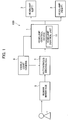
- the headlamp control system 100 includes the headlamp control device 1, headlamps 3, a visible light camera 5, an autonomous driving ECU 7, and a human interface 9.
- the headlamp control system 100 is installed in a vehicle enabling autonomous driving.
- the headlamps 3 are headlamps, such as intelligent headlamps and adaptive high beams, that can regulate lighting depending on the road condition ahead of the vehicle.
- the headlamps 3 are each provided with a plurality of light sources typically using light emitting diodes (LEDs) arranged in a matrix form. Each of the light sources is controlled so as to regulate the lighting.
- the headlamps 3 are thus configured to control the irradiation amount, in the irradiation range ahead of the vehicle, at the irradiation positions of the respective light sources arranged into the matrix form.
- the light sources of the headlamps 3 emitting the light toward the position of the oncoming vehicle are turned off so as to emit the light to the irradiation range with the light, excluding only the position of the oncoming vehicle.
- the headlamps 3 are typically, but not necessarily, installed at the right and left parts on the front side of the vehicle.
- the visible light camera 5 is a camera including an imaging device, such as a charge-coupled device (CCD) or a complementary metal oxide semiconductor (CMOS).
- the visible light camera 5 is installed in the vehicle so as to capture the condition around the vehicle to output captured images to the autonomous driving ECU 7 and the headlamp control device 1. Since the visible light camera 5 has a high sensitivity to light, the visible light camera 5 can detect obstacles present around the vehicle under the brightness lower than that necessary for the driver to drive manually.
- the autonomous driving ECU 7 is an electronic control unit that controls the autonomous driving of the vehicle.
- the autonomous driving ECU 7 acquires sensor values from a millimeter wave radar, a laser rangefinder, and the like (not illustrated), in addition to the images acquired from the visible light camera 5, and detects obstacles such as pedestrians and other vehicles present around the vehicle.
- the autonomous driving ECU 7 is connected to a group of sensors (not illustrated).
- the autonomous driving ECU 7 is connected to an acceleration sensor, a steering sensor, a brake sensor, and a viscosity sensor, so as to further acquire the sensor values output from the sensor group.
- the autonomous driving ECU 7 also acquires positional information of the vehicle from a GPS receiver mounted on the vehicle, and executes the autonomous driving control while referring to map information stored in a car navigation device.
- the autonomous driving executed by the autonomous driving ECU 7 is not intervened by the driver, and is in Level 3 or higher.
- the autonomous driving is executed by the autonomous driving ECU 7 at least in accordance with the images captured by the visible light camera 5 for capturing the circumference of the vehicle.
- the autonomous driving executed by the autonomous driving ECU 7 may be based on the images acquired by the visible light camera 5 and the data acquired by the sensor group.
- autonomous driving mode a mode in which the vehicle is driven in accordance with the images captured by the visible light camera 5 for capturing the circumference of the vehicle
- manual driving mode a mode in which the vehicle is driven by the driver
- the human interface 9 is an input device that receives the operation by the occupant (including the driver) of the vehicle, and is a display of a touch panel, or a steering switch provided on the steering wheel, for example.
- the operation of switching between the autonomous driving mode and the manual driving mode is input by the occupant in the vehicle through the human interface 9, or a warning is output from the human interface 9 to notify the occupant in the vehicle.
- the headlamp control device 1 is a controller for executing the control of the headlamps 3, for example, controls the lighting of the headlamps 3.
- the headlamp control device 1 acquires the images from the visible light camera 5, and acquires the detection information on obstacles and the information necessary for the autonomous driving mode from the autonomous driving ECU 7.
- the information that the headlamp control device 1 acquires includes the sensor values such as a velocity.
- the headlamp control device 1 controls the irradiation amount of the headlamps 3 to regulate the lighting depending on the road condition ahead of the vehicle.
- the headlamp control device 1 includes a control unit for processing the data acquired from the visible light camera 5 and the autonomous driving ECU 7, and is fabricated by an IC or LSI.
- the headlamp control device 1 may be an ECU for controlling the headlamps 3.
- the headlamp control device 1 may be classified as a headlamp control unit 11 when defined as a functional unit.
- the headlamp control device 1 may be fabricated by a microcomputer, a microprocessor, a general-purpose electronic circuit including a CPU, and a peripheral device such as a memory.
- the respective functions of the headlamp control device 1 are implemented in single or plural processing circuits.
- the respective processing circuits may include a programmed processing device, such as a processing device including an electric circuit.
- the respective processing circuits may include an application-specific integrated circuit (ASIC) configured to execute the functions described in the present embodiment, or conventional circuit components.
- ASIC application-specific integrated circuit
- the headlamp control unit 11 determines whether the vehicle is either in the autonomous driving mode or in the manual driving mode driven by the driver of the vehicle, in accordance with the information acquired from the autonomous driving ECU 7. When the vehicle is in the autonomous driving mode, the headlamp control unit 11 controls the headlamps 3 so as to emit light set to the irradiation amount necessary for the autonomous driving mode. When the vehicle is in the manual driving mode, the headlamp control unit 11 may control the headlamps 3 so as to be set to normal low beams or high beams, or may control the headlamps 3 so as to emit light set to the irradiation amount suitable for the manual driving mode.
- the irradiation amount necessary for the autonomous driving mode may be determined depending on the result of experiments or simulations.
- the irradiation amount suitable for the manual driving mode may also be determined depending on the result of experiments or simulations.
- the irradiation amount may vary depending on the type and the size of the vehicle.
- the headlamp control processing executed by the headlamp control device 1 is described below with reference to Fig. 2 and Fig. 3 .
- step S101 shown in Fig. 2 the headlamp control unit 11 determines whether the vehicle is in the autonomous driving mode in accordance with the information acquired from the autonomous driving ECU 7. The process proceeds to step S103 when the vehicle is in the autonomous driving mode (Yes in step S101). The process proceeds to step S105 when the vehicle is in the manual driving mode driven by the driver (No in step S101).
- step S103 the headlamp control unit 11 decreases the irradiation amount of the headlamps 3 during the autonomous driving mode so as to be smaller than the irradiation amount in the manual driving mode.
- the autonomous driving function is OFF before the time T1.
- the vehicle is thus in the manual driving mode driven by the driver before the time T1.
- the irradiation amount of the headlamps 3 in the manual driving mode is set to be an appropriate amount as described above.
- the vehicle is switched from the manual driving mode to the autonomous driving mode.
- Fig. 3 the vehicle is switched from the manual driving mode to the autonomous driving mode.
- the headlamp control unit 11 decreases the irradiation amount of the headlamps 3 so as to be smaller than that in the manual driving mode.
- the autonomous driving is executed by the autonomous driving ECU 7 in accordance with the images acquired by the visible light camera 5. Since the sensitivity of the visible light camera 5 to light is higher than the sensitivity of human eyes to light, unnecessary energy would be consumed during the autonomous driving mode if the irradiation amount of the headlamps 3 in the autonomous driving mode is set to be equivalent to that in the manual driving mode.
- the headlamp control unit 11 sets the irradiation amount of the headlamps 3 in the autonomous driving mode to be smaller than that of the headlamps 3 in the manual driving mode.
- the headlamp control unit 11 thus can save the irradiation amount of the headlamps 3. Namely, the headlamp control unit 11 can suppress or reduce the energy consumed by the irradiation of light from the headlamps 3 in the autonomous driving mode.
- step S105 in the manual driving mode, the headlamp control unit 11 does not change the irradiation amount of the headlamps 3.
- the headlamp control unit 11 may synchronize the timing of switching the headlamps 3 between the ON state and the OFF state with a frame rate of the visible light camera 5.
- the specific explanations are made below with reference to Fig. 4 and Fig. 5 .
- step S203 the headlamp control unit 11 acquires a frame rate of the visible light camera 5.
- frame rate refers to the number of frames processed by the visible light camera 5 per unit time.
- the frame rate of the visible light camera 5 is determined as appropriate, and is herein set to several tens of Hz.
- the visible light camera 5 repeats the operation of turning ON and OFF according to the frame rate preliminarily set.
- the headlamps 3 are only required to emit the light when the visible light camera 5 is in the ON state. That is, the headlamps 3 do not necessarily emit the light when the visible light camera 5 is in the OFF state.
- the headlamp control unit 11 may synchronize the timing of switching the headlamps 3 between the ON state and the OFF state with the frame rate of the visible light camera 5 (in step S205 shown in Fig. 4 ). The headlamp control unit 11 thus can further reduce the energy consumed by the irradiation of light from the headlamps 3.
- step S207 shown in Fig. 4 is the same as in step S105 shown in Fig. 2 , and overlapping explanations are not repeated below.
- the headlamp control unit 11 may also decreases the irradiation amount of the headlamps 3 depending on the condition around the vehicle. The specific explanations are made below with reference to Fig. 6 .
- step S303 the headlamp control unit 11 acquires an intensity of illumination around the vehicle according to the information acquired by the visible light camera 5 or an illumination sensor (not illustrated) installed in the vehicle.
- the intensity of illumination around the vehicle is greater as the number of street lights around the vehicle is greater.
- the intensity of illumination around the vehicle also increases as the number of other vehicles around the vehicle increases.
- the autonomous driving ECU7 can use the light around the vehicle so as to detect obstacles.
- the headlamp control unit 11 thus may further decrease the irradiation amount in the autonomous driving mode when the intensity of illumination around the vehicle is high, as compared with the case in which the intensity of illumination is low.
- the headlamp control unit 11 can further reduce the energy consumed by the irradiation of light from the headlamps 3 accordingly.
- the headlamp control unit 11 may narrow the irradiation range of the headlamps 3 when the intensity of illumination around the vehicle is high, as compared with the case in which the intensity of illumination is low. For example, when a street light lights up a road sign above the vehicle, the headlamps 3 do not necessarily light up the sign.
- the headlamp control unit 11, when narrowing the irradiation range of the headlamps 3, thus can further reduce the energy consumed by the irradiation of light from the headlamps 3.
- the headlamp control unit 11 may control the headlamps 3 depending on the intensity of illumination around the vehicle.
- the intensity of illumination around the vehicle includes the characteristics of a road sign (such as color and reflectance).
- the headlamp control unit 3 may widen the irradiation range of the headlamps 3 in accordance with the characteristics of the road sign (such as color and reflectance).
- the headlamp control unit 11, when widening the irradiation range of the headlamps 3, may increase the irradiation amount of the headlamps 3.
- the headlamp control unit 11 thus can provide the irradiation range and the irradiation amount suitable for the driver.
- the headlamp control unit 11 regulates the irradiation amount of the headlamps 3 depending on the presence or absence of a fault in the autonomous driving mode. The specific explanations are made below with reference to Fig. 7 to Fig. 10 .
- step S405 the headlamp control unit 11 detects the presence or absence of a fault in the autonomous driving mode.
- the phrase "the presence of a fault in the autonomous driving mode" refers to a state in which the autonomous driving mode is not being executed normally.
- This information is presented in view of the time necessary for the switching operation.
- a warning switch
- the headlamp control unit 11 increases the irradiation amount during the period until the operation of switching from the autonomous driving mode to the manual driving mode is completed (during the period from the time T3 to the time T4) so as to be greater than the irradiation amount during the autonomous driving mode (during the period from the time T2 to the time T3).
- FIG. 8 illustrates the case in which the headlamp control unit 11 sets the irradiation amount to be the same as the irradiation amount in the manual driving mode until the operation of switching from the autonomous driving mode to the manual driving mode is completed.
- the driver thus can accurately recognize the condition around the vehicle during the period until the operation of switching from the autonomous driving mode to the manual driving mode is completed.
- the example of operation at the time T1 and the time T2 shown in Fig. 8 is the same as that shown in Fig. 3 , and overlapping explanations are not repeated below.
- a warning indicating "Please have the vehicle served at the dealer", for example, may be displayed on the display until the fault in the autonomous driving mode is cleared away after the time T4.
- the headlamp control unit 11 sets the irradiation amount to be the same as the irradiation amount in the manual driving mode until the operation of switching from the autonomous driving mode to the manual driving mode is completed.
- the headlamp control unit 11 is only required to set the irradiation amount to be greater than that in the autonomous driving mode until the operation of switching from the autonomous driving mode to the manual driving mode is completed.
- the headlamp control unit 11 then only needs to set the irradiation amount at the time when the operation of switching from the autonomous driving mode to the manual driving mode is completed (at the time T4) to be the same as the irradiation amount in the manual driving mode.
- the driver may be dazzled by the glare of light.
- increasing the irradiation amount while taking the two steps as shown in Fig. 9 can reduce the driver's discomfort.
- the headlamp control unit 11 may gradually increase the irradiation amount during the period until the operation of switching from the autonomous driving mode to the manual driving mode is completed.
- the headlamp control unit 11 then only needs to set the irradiation amount at the time when the operation of switching from the autonomous driving mode to the manual driving mode is completed (at the time T4) to be the same as the irradiation amount in the manual driving mode, as in the case shown in Fig. 9 .
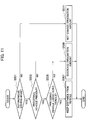
- the headlamp control unit 11 may also regulate the irradiation amount of the headlamps 3 depending on the determination of whether a preceding vehicle is a large-sized vehicle. The specific explanations are made below with reference to Fig. 11 .
- step S503 the headlamp control unit 11 determines whether a preceding vehicle traveling in front of the vehicle is present according to the information acquired from the visible light camera 5 or the sensor group. The process proceeds to step S505 when the preceding vehicle is present (Yes in step S503). When there is no preceding vehicle (No in step S503), the process proceeds to step S509. In step S505, the headlamp control unit 11 determines whether the preceding vehicle is a large-sized vehicle (such as a truck).
- step S509 when the preceding vehicle is not a large-sized vehicle (No in step S505), and the headlamp control unit 11 then decreases the irradiation amount of the headlamps 3.
- the determination that the preceding vehicle is not a large-sized vehicle indicates that the preceding vehicle is a standard-sized vehicle.
- the reason for the operation of decreasing the irradiation amount of the headlamps 3 by the headlamp control unit 11 is to avoid dazzling the driver in the preceding vehicle by the glare of light.
- step S507 when the preceding vehicle is a large-sized vehicle (Yes in step S505), and the autonomous driving ECU 7 causes the vehicle to keep the distance from the preceding vehicle.
- the headlamp control device 1 according to the present embodiment described above can achieve the following effects.
- the vehicle according to the present embodiment is equipped with the autonomous driving mode driven in accordance with the images acquired by the visible light camera 5 for capturing the circumference of the vehicle, and the manual driving mode driven by the driver of the vehicle. Since the sensitivity of the visible light camera 5 to light is higher than the sensitivity of human eyes to light, unnecessary energy would be consumed during the autonomous driving mode if the irradiation amount of the headlamps 3 in the autonomous driving mode is set to be equivalent to that in the manual driving mode. In view of this, the headlamp control unit 11 sets the irradiation amount of the headlamps 3 in the autonomous driving mode to be smaller than that in the manual driving mode. The headlamp control unit 11 thus can save the irradiation amount of the headlamps 3. Namely, the headlamp control unit 11 can suppress or reduce the energy consumed by the irradiation of light from the headlamps 3 in the autonomous driving mode.
- the headlamp control unit 11 detects the presence or absence of a fault in the autonomous driving mode. When a fault in the autonomous driving mode is detected, the headlamp control unit 11 sets may the irradiation amount to be equal to the manual driving mode until the operation of switching from the autonomous driving mode to the manual driving mode is completed. In addition, the driver can accurately recognize the condition around the vehicle when the operation of switching from the autonomous driving mode to the manual driving mode is completed.
- the headlamp control unit 11 may synchronize the timing of switching the headlamps 3 between the ON state and the OFF state with the frame rate of the visible light camera 5.
- the visible light camera 5 repeats the operation of turning ON and OFF according to the frame rate preliminarily set. Since the visible light camera 5 senses the light when in the ON state, the headlamps 3 are only required to emit light when the visible light camera 5 is in the ON state. The headlamp control unit 11 thus can further reduce the energy consumed by the irradiation of light from the headlamps 3.
- the headlamp control unit 11 may decrease the irradiation amount of the headlamps 3 when the intensity of illumination around the vehicle is high, as compared with the case in which the intensity of illumination is low. Since the autonomous driving ECU7 can use the light around the vehicle to detect obstacles when the intensity of illumination around the vehicle is high, the headlamp control unit 11 can further reduce the energy consumed by the irradiation of light from the headlamps 3.
- the respective functions described in the above embodiment can be implemented in single or plural processing circuits.
- the respective processing circuits include a programmed processing device, such as a processing device including an electric circuit.
- the respective processing circuits include an application-specific integrated circuit (ASIC) configured to execute the functions described above, and devices such as circuit components.
- ASIC application-specific integrated circuit
- the headlamp control device 1 can improve the functions of a computer.
- the irradiation range necessary for the autonomous driving mode described above may be set to a range allowing the headlamp control device to detect obstacles present in a region requiring a safety check when executing the autonomous driving mode.
Landscapes
- Engineering & Computer Science (AREA)
- Mechanical Engineering (AREA)
- Automation & Control Theory (AREA)
- Human Computer Interaction (AREA)
- Transportation (AREA)
- Lighting Device Outwards From Vehicle And Optical Signal (AREA)
Description
- The present invention relates to a headlamp control method and a headlamp control device.
- Methods of controlling headlamps are known that improve the accuracy of recognition of targets, such as oncoming vehicles and pedestrians, while avoiding dazzling occupants in the oncoming vehicles or the pedestrians by the glare of light (Patent Document 1).
- Patent Document 1:
JP 2012-171499 A - The irradiation of light from headlamps is typically set to the amount suitable for drivers. In recent years, research and development have been promoted regarding autonomous driving. If the amount of light emitted from headlamps used in an autonomous driving mode is set to be equivalent to that used in a manual driving mode, unnecessary energy is inevitably consumed. The reason for this is that, since the information around a host vehicle is detected by a visible light camera, and the sensitivity of the visible light camera to light is higher than the sensitivity of human eyes to light, only a small irradiation amount of the headlamps is sufficient for the autonomous driving mode, as compared with the irradiation amount of the headlamps in the manual driving mode.
Patent Document 1 does not mention the comparison between the irradiation amount of the headlamps in the autonomous driving mode and that in the manual driving mode. The invention disclosed inPatent Document 1 thus cannot suppress or reduce the energy consumed by the irradiation of light from the headlamps in the autonomous driving mode. - Document
DE 10 2015 200 859 Al discloses a method and a device for controlling a headlamp installed in an vehicle comprising both an autonomous and a manual driving modes, wherein the amount of light generated by the headlamp is lower when the vehicle is in the autonomous driving mode than in the manual driving mode. - In view of the foregoing problem, the present invention provides a headlamp control method and a headlamp control device as defined in
claim 1 respectively claim 4. - A headlamp control method according to an aspect of the present invention decreases the irradiation amount of a headlamp in an autonomous driving mode so as to be smaller than the irradiation amount of the headlamp in a manual driving mode, and when a fault in the autonomous driving mode is detected, the irradiation amount is set to be equal to the irradiation amount in the manual driving mode until an operation of switching from the autonomous driving mode to the manual driving mode is completed.
- The present invention can reduce the energy consumed by the irradiation of light from headlamps in the autonomous driving mode.
-
- [
Fig. 1] Fig. 1 is a schematic configuration diagram illustrating a headlamp control system according to an embodiment of the present invention. - [
Fig. 2] Fig. 2 is a flowchart illustrating an example of operation of a headlamp control device according to the embodiment of the present invention. - [
Fig. 3] Fig. 3 is a diagram for explaining headlamp control processing in one example performed by the headlamp control device. - [
Fig. 4] Fig. 4 is a flowchart illustrating an example of operation of the headlamp control device according to the embodiment of the present invention. - [
Fig. 5] Fig. 5 is a diagram for explaining headlamp control processing in one example performed by the headlamp control device. - [
Fig. 6] Fig. 6 is a flowchart illustrating an example of operation of the headlamp control device according to the embodiment of the present invention. - [
Fig. 7] Fig. 7 is a flowchart illustrating an example of operation of the headlamp control device according to the embodiment of the present invention. - [
Fig. 8] Fig. 8 is a diagram for explaining headlamp control processing in one example performed by the headlamp control device. - [
Fig. 9] Fig. 9 is a diagram for explaining headlamp control processing in one example, which is not part of the present invention. - [
Fig. 10] Fig. 10 is a diagram for explaining headlamp control processing in one example, which is not part of the present invention. - [
Fig. 11] Fig. 11 is a flowchart illustrating an example of operation of the headlamp control device according to the embodiment of the present invention. - An embodiment of the present invention will be described below with reference to the drawings. The same elements illustrated in the drawings are indicated by the same reference numerals, and overlapping explanations are not made below.
- A configuration of a
headlamp control system 100 including aheadlamp control device 1 according to the present embodiment is described below with reference toFig. 1 . As illustrated inFig. 1 , theheadlamp control system 100 includes theheadlamp control device 1,headlamps 3, avisible light camera 5, anautonomous driving ECU 7, and ahuman interface 9. Theheadlamp control system 100 is installed in a vehicle enabling autonomous driving. - The
headlamps 3 are headlamps, such as intelligent headlamps and adaptive high beams, that can regulate lighting depending on the road condition ahead of the vehicle. In particular, theheadlamps 3 are each provided with a plurality of light sources typically using light emitting diodes (LEDs) arranged in a matrix form. Each of the light sources is controlled so as to regulate the lighting. Theheadlamps 3 are thus configured to control the irradiation amount, in the irradiation range ahead of the vehicle, at the irradiation positions of the respective light sources arranged into the matrix form. For example, when an oncoming vehicle ahead of the vehicle is coming closer to the vehicle, the light sources of theheadlamps 3 emitting the light toward the position of the oncoming vehicle are turned off so as to emit the light to the irradiation range with the light, excluding only the position of the oncoming vehicle. Theheadlamps 3 are typically, but not necessarily, installed at the right and left parts on the front side of the vehicle. - The
visible light camera 5 is a camera including an imaging device, such as a charge-coupled device (CCD) or a complementary metal oxide semiconductor (CMOS). Thevisible light camera 5 is installed in the vehicle so as to capture the condition around the vehicle to output captured images to theautonomous driving ECU 7 and theheadlamp control device 1. Since thevisible light camera 5 has a high sensitivity to light, thevisible light camera 5 can detect obstacles present around the vehicle under the brightness lower than that necessary for the driver to drive manually. - The autonomous driving ECU 7 is an electronic control unit that controls the autonomous driving of the vehicle. The autonomous driving ECU 7 acquires sensor values from a millimeter wave radar, a laser rangefinder, and the like (not illustrated), in addition to the images acquired from the
visible light camera 5, and detects obstacles such as pedestrians and other vehicles present around the vehicle. Theautonomous driving ECU 7 is connected to a group of sensors (not illustrated). For example, theautonomous driving ECU 7 is connected to an acceleration sensor, a steering sensor, a brake sensor, and a viscosity sensor, so as to further acquire the sensor values output from the sensor group. Theautonomous driving ECU 7 also acquires positional information of the vehicle from a GPS receiver mounted on the vehicle, and executes the autonomous driving control while referring to map information stored in a car navigation device. The autonomous driving executed by theautonomous driving ECU 7 is not intervened by the driver, and is inLevel 3 or higher. The autonomous driving is executed by theautonomous driving ECU 7 at least in accordance with the images captured by thevisible light camera 5 for capturing the circumference of the vehicle. The autonomous driving executed by theautonomous driving ECU 7 may be based on the images acquired by thevisible light camera 5 and the data acquired by the sensor group. The following case is illustrated with a mode in which the vehicle is driven in accordance with the images captured by thevisible light camera 5 for capturing the circumference of the vehicle, which is referred to also as an "autonomous driving mode", and a mode in which the vehicle is driven by the driver, which is referred to also as a "manual driving mode". - The
human interface 9 is an input device that receives the operation by the occupant (including the driver) of the vehicle, and is a display of a touch panel, or a steering switch provided on the steering wheel, for example. The operation of switching between the autonomous driving mode and the manual driving mode is input by the occupant in the vehicle through thehuman interface 9, or a warning is output from thehuman interface 9 to notify the occupant in the vehicle. - The
headlamp control device 1 is a controller for executing the control of theheadlamps 3, for example, controls the lighting of theheadlamps 3. In particular, theheadlamp control device 1 acquires the images from thevisible light camera 5, and acquires the detection information on obstacles and the information necessary for the autonomous driving mode from theautonomous driving ECU 7. The information that theheadlamp control device 1 acquires includes the sensor values such as a velocity. Theheadlamp control device 1 controls the irradiation amount of theheadlamps 3 to regulate the lighting depending on the road condition ahead of the vehicle. - The
headlamp control device 1 includes a control unit for processing the data acquired from thevisible light camera 5 and theautonomous driving ECU 7, and is fabricated by an IC or LSI. Theheadlamp control device 1 may be an ECU for controlling theheadlamps 3. Theheadlamp control device 1 may be classified as aheadlamp control unit 11 when defined as a functional unit. - The
headlamp control device 1 may be fabricated by a microcomputer, a microprocessor, a general-purpose electronic circuit including a CPU, and a peripheral device such as a memory. The respective functions of theheadlamp control device 1 are implemented in single or plural processing circuits. The respective processing circuits may include a programmed processing device, such as a processing device including an electric circuit. The respective processing circuits may include an application-specific integrated circuit (ASIC) configured to execute the functions described in the present embodiment, or conventional circuit components. - The
headlamp control unit 11 determines whether the vehicle is either in the autonomous driving mode or in the manual driving mode driven by the driver of the vehicle, in accordance with the information acquired from theautonomous driving ECU 7. When the vehicle is in the autonomous driving mode, theheadlamp control unit 11 controls theheadlamps 3 so as to emit light set to the irradiation amount necessary for the autonomous driving mode. When the vehicle is in the manual driving mode, theheadlamp control unit 11 may control theheadlamps 3 so as to be set to normal low beams or high beams, or may control theheadlamps 3 so as to emit light set to the irradiation amount suitable for the manual driving mode. The irradiation amount necessary for the autonomous driving mode may be determined depending on the result of experiments or simulations. The irradiation amount suitable for the manual driving mode may also be determined depending on the result of experiments or simulations. The irradiation amount may vary depending on the type and the size of the vehicle. - The headlamp control processing executed by the
headlamp control device 1 is described below with reference toFig. 2 and Fig. 3 . - In step S101 shown in
Fig. 2 , theheadlamp control unit 11 determines whether the vehicle is in the autonomous driving mode in accordance with the information acquired from theautonomous driving ECU 7. The process proceeds to step S103 when the vehicle is in the autonomous driving mode (Yes in step S101). The process proceeds to step S105 when the vehicle is in the manual driving mode driven by the driver (No in step S101). - In step S103, the
headlamp control unit 11 decreases the irradiation amount of theheadlamps 3 during the autonomous driving mode so as to be smaller than the irradiation amount in the manual driving mode. This step is described in more detail below with reference toFig. 3 . As illustrated inFig. 3 , the autonomous driving function is OFF before the time T1. The vehicle is thus in the manual driving mode driven by the driver before the time T1. The irradiation amount of theheadlamps 3 in the manual driving mode is set to be an appropriate amount as described above. When the occupant operates thehuman interface 9 so as to switch the autonomous driving function from OFF to ON at the time T1, the vehicle is switched from the manual driving mode to the autonomous driving mode. As illustrated inFig. 3 , when the vehicle is switched from the manual driving mode to the autonomous driving mode at the time T1, theheadlamp control unit 11 decreases the irradiation amount of theheadlamps 3 so as to be smaller than that in the manual driving mode. As described above, the autonomous driving is executed by theautonomous driving ECU 7 in accordance with the images acquired by the visiblelight camera 5. Since the sensitivity of the visiblelight camera 5 to light is higher than the sensitivity of human eyes to light, unnecessary energy would be consumed during the autonomous driving mode if the irradiation amount of theheadlamps 3 in the autonomous driving mode is set to be equivalent to that in the manual driving mode. In view of this, theheadlamp control unit 11 sets the irradiation amount of theheadlamps 3 in the autonomous driving mode to be smaller than that of theheadlamps 3 in the manual driving mode. Theheadlamp control unit 11 thus can save the irradiation amount of theheadlamps 3. Namely, theheadlamp control unit 11 can suppress or reduce the energy consumed by the irradiation of light from theheadlamps 3 in the autonomous driving mode. In step S105, in the manual driving mode, theheadlamp control unit 11 does not change the irradiation amount of theheadlamps 3. - The
headlamp control unit 11 may synchronize the timing of switching theheadlamps 3 between the ON state and the OFF state with a frame rate of the visiblelight camera 5. The specific explanations are made below with reference toFig. 4 andFig. 5 . - The process in step S201 shown in
Fig. 4 is the same as in step S101 shown inFig. 2 , and overlapping explanations are not repeated below. In step S203, theheadlamp control unit 11 acquires a frame rate of the visiblelight camera 5. The term "frame rate" as used herein refers to the number of frames processed by the visiblelight camera 5 per unit time. The frame rate of the visiblelight camera 5 is determined as appropriate, and is herein set to several tens of Hz. As illustrated inFig. 5 , the visiblelight camera 5 repeats the operation of turning ON and OFF according to the frame rate preliminarily set. Since the visiblelight camera 5 senses the light when in the ON state, theheadlamps 3 are only required to emit the light when the visiblelight camera 5 is in the ON state. That is, theheadlamps 3 do not necessarily emit the light when the visiblelight camera 5 is in the OFF state. As illustrated inFig. 5 , theheadlamp control unit 11 may synchronize the timing of switching theheadlamps 3 between the ON state and the OFF state with the frame rate of the visible light camera 5 (in step S205 shown inFig. 4 ). Theheadlamp control unit 11 thus can further reduce the energy consumed by the irradiation of light from theheadlamps 3. The timing of switching theheadlamps 3 between the ON state and the OFF state can be referred to as the timing of switching theheadlamps 3 between the lighting-up state and turned-off state. The process in step S207 shown inFig. 4 is the same as in step S105 shown inFig. 2 , and overlapping explanations are not repeated below. - The
headlamp control unit 11 may also decreases the irradiation amount of theheadlamps 3 depending on the condition around the vehicle. The specific explanations are made below with reference toFig. 6 . - The process in step S301 shown in
Fig. 6 is the same as in step S101 shown inFig. 2 , and overlapping explanations are not repeated below. In step S303, theheadlamp control unit 11 acquires an intensity of illumination around the vehicle according to the information acquired by the visiblelight camera 5 or an illumination sensor (not illustrated) installed in the vehicle. The intensity of illumination around the vehicle is greater as the number of street lights around the vehicle is greater. The intensity of illumination around the vehicle also increases as the number of other vehicles around the vehicle increases. When the intensity of illumination around the vehicle is high, the autonomous driving ECU7 can use the light around the vehicle so as to detect obstacles. Theheadlamp control unit 11 thus may further decrease the irradiation amount in the autonomous driving mode when the intensity of illumination around the vehicle is high, as compared with the case in which the intensity of illumination is low. Theheadlamp control unit 11 can further reduce the energy consumed by the irradiation of light from theheadlamps 3 accordingly. - As shown in step S305, the
headlamp control unit 11 may narrow the irradiation range of theheadlamps 3 when the intensity of illumination around the vehicle is high, as compared with the case in which the intensity of illumination is low. For example, when a street light lights up a road sign above the vehicle, theheadlamps 3 do not necessarily light up the sign. Theheadlamp control unit 11, when narrowing the irradiation range of theheadlamps 3, thus can further reduce the energy consumed by the irradiation of light from theheadlamps 3. - In step S307, in the manual driving mode, the
headlamp control unit 11 may control theheadlamps 3 depending on the intensity of illumination around the vehicle. The intensity of illumination around the vehicle includes the characteristics of a road sign (such as color and reflectance). In step S309, theheadlamp control unit 3 may widen the irradiation range of theheadlamps 3 in accordance with the characteristics of the road sign (such as color and reflectance). Theheadlamp control unit 11, when widening the irradiation range of theheadlamps 3, may increase the irradiation amount of theheadlamps 3. Theheadlamp control unit 11 thus can provide the irradiation range and the irradiation amount suitable for the driver. - The
headlamp control unit 11 regulates the irradiation amount of theheadlamps 3 depending on the presence or absence of a fault in the autonomous driving mode. The specific explanations are made below with reference toFig. 7 to Fig. 10 . - The process in steps S401, S403, and S409 shown in
Fig. 7 is the same as in steps S101, S103, and S105 shown inFig. 2 , and overlapping explanations are not repeated below. In step S405, theheadlamp control unit 11 detects the presence or absence of a fault in the autonomous driving mode. The phrase "the presence of a fault in the autonomous driving mode" refers to a state in which the autonomous driving mode is not being executed normally. When a fault in the autonomous driving mode is detected (Yes in step S405), the process proceeds to step S407, and the autonomous driving mode is switched to the manual driving mode. The switching operation may be informed with voice saying "An error has been detected in the autonomous driving. Please switch to the manual driving", for example. This information is presented in view of the time necessary for the switching operation. When theheadlamp control unit 11 detects a fault in the autonomous driving mode at the time T3 shown inFig. 8 , a warning (switch) is informed, and theheadlamp control unit 11 then increases the irradiation amount during the period until the operation of switching from the autonomous driving mode to the manual driving mode is completed (during the period from the time T3 to the time T4) so as to be greater than the irradiation amount during the autonomous driving mode (during the period from the time T2 to the time T3).Fig. 8 illustrates the case in which theheadlamp control unit 11 sets the irradiation amount to be the same as the irradiation amount in the manual driving mode until the operation of switching from the autonomous driving mode to the manual driving mode is completed. The driver thus can accurately recognize the condition around the vehicle during the period until the operation of switching from the autonomous driving mode to the manual driving mode is completed. The example of operation at the time T1 and the time T2 shown inFig. 8 is the same as that shown inFig. 3 , and overlapping explanations are not repeated below. A warning indicating "Please have the vehicle served at the dealer", for example, may be displayed on the display until the fault in the autonomous driving mode is cleared away after the time T4. - According to the invention, the
headlamp control unit 11 sets the irradiation amount to be the same as the irradiation amount in the manual driving mode until the operation of switching from the autonomous driving mode to the manual driving mode is completed. According to an example, which is not part of the present invention, as shown inFig. 9 , theheadlamp control unit 11 is only required to set the irradiation amount to be greater than that in the autonomous driving mode until the operation of switching from the autonomous driving mode to the manual driving mode is completed. Theheadlamp control unit 11 then only needs to set the irradiation amount at the time when the operation of switching from the autonomous driving mode to the manual driving mode is completed (at the time T4) to be the same as the irradiation amount in the manual driving mode. If the irradiation amount of theheadlamps 3 is increased rapidly during the switching operation, the driver may be dazzled by the glare of light. In view of this, increasing the irradiation amount while taking the two steps as shown inFig. 9 can reduce the driver's discomfort. - According to another example, which is not part of the present invention. as shown in
Fig. 10 , theheadlamp control unit 11 may gradually increase the irradiation amount during the period until the operation of switching from the autonomous driving mode to the manual driving mode is completed. Theheadlamp control unit 11 then only needs to set the irradiation amount at the time when the operation of switching from the autonomous driving mode to the manual driving mode is completed (at the time T4) to be the same as the irradiation amount in the manual driving mode, as in the case shown inFig. 9 . - The
headlamp control unit 11 may also regulate the irradiation amount of theheadlamps 3 depending on the determination of whether a preceding vehicle is a large-sized vehicle. The specific explanations are made below with reference toFig. 11 . - The process in steps S501, S509, and S511 shown in
Fig. 11 is the same as in steps S101, S103, and S105 shown inFig. 2 , and overlapping explanations are not repeated below. In step S503, theheadlamp control unit 11 determines whether a preceding vehicle traveling in front of the vehicle is present according to the information acquired from the visiblelight camera 5 or the sensor group. The process proceeds to step S505 when the preceding vehicle is present (Yes in step S503). When there is no preceding vehicle (No in step S503), the process proceeds to step S509. In step S505, theheadlamp control unit 11 determines whether the preceding vehicle is a large-sized vehicle (such as a truck). The process proceeds to step S509 when the preceding vehicle is not a large-sized vehicle (No in step S505), and theheadlamp control unit 11 then decreases the irradiation amount of theheadlamps 3. The determination that the preceding vehicle is not a large-sized vehicle indicates that the preceding vehicle is a standard-sized vehicle. The reason for the operation of decreasing the irradiation amount of theheadlamps 3 by theheadlamp control unit 11 is to avoid dazzling the driver in the preceding vehicle by the glare of light. The process proceeds to step S507 when the preceding vehicle is a large-sized vehicle (Yes in step S505), and theautonomous driving ECU 7 causes the vehicle to keep the distance from the preceding vehicle. - The
headlamp control device 1 according to the present embodiment described above can achieve the following effects. - The vehicle according to the present embodiment is equipped with the autonomous driving mode driven in accordance with the images acquired by the visible
light camera 5 for capturing the circumference of the vehicle, and the manual driving mode driven by the driver of the vehicle. Since the sensitivity of the visiblelight camera 5 to light is higher than the sensitivity of human eyes to light, unnecessary energy would be consumed during the autonomous driving mode if the irradiation amount of theheadlamps 3 in the autonomous driving mode is set to be equivalent to that in the manual driving mode. In view of this, theheadlamp control unit 11 sets the irradiation amount of theheadlamps 3 in the autonomous driving mode to be smaller than that in the manual driving mode. Theheadlamp control unit 11 thus can save the irradiation amount of theheadlamps 3. Namely, theheadlamp control unit 11 can suppress or reduce the energy consumed by the irradiation of light from theheadlamps 3 in the autonomous driving mode. - The
headlamp control unit 11 detects the presence or absence of a fault in the autonomous driving mode. When a fault in the autonomous driving mode is detected, theheadlamp control unit 11 sets may the irradiation amount to be equal to the manual driving mode until the operation of switching from the autonomous driving mode to the manual driving mode is completed. In addition, the driver can accurately recognize the condition around the vehicle when the operation of switching from the autonomous driving mode to the manual driving mode is completed. - The
headlamp control unit 11 may synchronize the timing of switching theheadlamps 3 between the ON state and the OFF state with the frame rate of the visiblelight camera 5. The visiblelight camera 5 repeats the operation of turning ON and OFF according to the frame rate preliminarily set. Since the visiblelight camera 5 senses the light when in the ON state, theheadlamps 3 are only required to emit light when the visiblelight camera 5 is in the ON state. Theheadlamp control unit 11 thus can further reduce the energy consumed by the irradiation of light from theheadlamps 3. - The
headlamp control unit 11 may decrease the irradiation amount of theheadlamps 3 when the intensity of illumination around the vehicle is high, as compared with the case in which the intensity of illumination is low. Since the autonomous driving ECU7 can use the light around the vehicle to detect obstacles when the intensity of illumination around the vehicle is high, theheadlamp control unit 11 can further reduce the energy consumed by the irradiation of light from theheadlamps 3. - The respective functions described in the above embodiment can be implemented in single or plural processing circuits. The respective processing circuits include a programmed processing device, such as a processing device including an electric circuit. The respective processing circuits include an application-specific integrated circuit (ASIC) configured to execute the functions described above, and devices such as circuit components. The
headlamp control device 1 can improve the functions of a computer. - While the present invention has been described above by reference to the embodiment, it should be understood that the present invention is not intended to be limited to the descriptions and the drawings composing part of this disclosure. Various alternative embodiments, examples, and technical applications will be apparent to those skilled in the art according to the invention whose scope is defined in the appended claims.
- The irradiation range necessary for the autonomous driving mode described above may be set to a range allowing the headlamp control device to detect obstacles present in a region requiring a safety check when executing the autonomous driving mode.
-
- 1
- HEADLAMP CONTROL DEVICE
- 3
- HEADLAMP
- 5
- VISIBLE LIGHT CAMERA
- 7
- AUTONOMOUS DRIVING ECU
- 9
- HUMAN INTERFACE
- 11
- HEADLAMP CONTROL UNIT
- 100
- HEADLAMP CONTROL SYSTEM
Claims (4)
- A headlamp control method of controlling a headlamp (3) so as to regulate an irradiation amount, the headlamp (3) being installed in a vehicle equipped with an autonomous driving mode driven in accordance with an image acquired by a visible light camera (5) for capturing a circumference of the vehicle and a manual driving mode driven by a driver of the vehicle, the method comprisingdecreasing the irradiation amount of the headlamp (3) in the autonomous driving mode so as to be smaller than the irradiation amount of the headlamp (3) in the manual driving mode; characterised by,when a fault in the autonomous driving mode is detected, setting the irradiation amount to be equal to the irradiation amount in the manual driving mode until an operation of switching from the autonomous driving mode to the manual driving mode is completed.
- The headlamp control method according to claim 1, wherein an operation of switching the headlamp (3) between ON and OFF is synchronized with a frame rate of the visible light camera (5).
- The headlamp control method according to claim 1 or 2, wherein the irradiation amount in the autonomous driving mode is decreased when an intensity of illumination around the vehicle is high as compared with a case in which the intensity of illumination is low.
- A headlamp control device (1) comprising a control unit (11) for controlling a headlamp (3) so as to regulate an irradiation amount, the headlamp (3) being installablein a vehicle equipped with an autonomous driving mode driven in accordance with an image acquired by a visible light camera (5) for capturing a circumference of the vehicle and a manual driving mode driven by a driver of the vehicle,the control unit (11) being configured to:
decrease the irradiation amount of the headlamp (3) in the autonomous driving mode so as to be smaller than the irradiation amount of the headlamp (3) in the manual driving mode; characterised in that,when a fault in the autonomous driving mode is detected, the control unit (11) sets the
irradiation amount to be equal to the irradiation amount in the manual driving mode until an operation of switching from the autonomous driving mode to the manual driving mode is completed.
Applications Claiming Priority (1)
| Application Number | Priority Date | Filing Date | Title |
|---|---|---|---|
| PCT/IB2018/001079 WO2020035713A1 (en) | 2018-08-14 | 2018-08-14 | Headlamp control method and headlamp control device |
Publications (3)
| Publication Number | Publication Date |
|---|---|
| EP3838670A1 EP3838670A1 (en) | 2021-06-23 |
| EP3838670A4 EP3838670A4 (en) | 2021-08-25 |
| EP3838670B1 true EP3838670B1 (en) | 2022-01-05 |
Family
ID=69525301
Family Applications (1)
| Application Number | Title | Priority Date | Filing Date |
|---|---|---|---|
| EP18930170.8A Active EP3838670B1 (en) | 2018-08-14 | 2018-08-14 | Headlamp control method and headlamp control device |
Country Status (6)
| Country | Link |
|---|---|
| US (1) | US11981249B2 (en) |
| EP (1) | EP3838670B1 (en) |
| JP (1) | JP7031750B2 (en) |
| CN (1) | CN112533794B (en) |
| RU (1) | RU2760074C1 (en) |
| WO (1) | WO2020035713A1 (en) |
Families Citing this family (5)
| Publication number | Priority date | Publication date | Assignee | Title |
|---|---|---|---|---|
| JP7095658B2 (en) * | 2019-07-11 | 2022-07-05 | トヨタ自動車株式会社 | In-vehicle device control device |
| US11560083B2 (en) * | 2020-08-20 | 2023-01-24 | Pony Ai Inc. | Autonomous headlamp encapsulated with camera and artificial intelligence processor to adjust illumination |
| JP7165230B2 (en) * | 2021-03-31 | 2022-11-02 | 本田技研工業株式会社 | LIGHT DISTRIBUTION CONTROL DEVICE, LIGHT DISTRIBUTION CONTROL METHOD, AND PROGRAM |
| CN113212292A (en) * | 2021-05-13 | 2021-08-06 | 蔚来汽车科技(安徽)有限公司 | Vehicle control method and device, vehicle-mounted equipment, vehicle and medium |
| US11964610B2 (en) | 2022-04-19 | 2024-04-23 | Toyota Research Institute, Inc. | Changing headlight properties to recommend vehicle speed |
Family Cites Families (20)
| Publication number | Priority date | Publication date | Assignee | Title |
|---|---|---|---|---|
| JP4011374B2 (en) * | 2002-03-18 | 2007-11-21 | 三菱電機株式会社 | In-vehicle power saving apparatus and in-vehicle power saving method |
| JP4302355B2 (en) * | 2002-03-20 | 2009-07-22 | 株式会社デンソー | Dazzle reduction device |
| JP5416542B2 (en) * | 2009-10-19 | 2014-02-12 | 株式会社小糸製作所 | Control system for vehicle headlamps |
| DE102009051485A1 (en) * | 2009-10-30 | 2010-06-17 | Daimler Ag | Method for controlling driving light of e.g. car, involves automatically activating light source of headlamp, and manually activating or deactivating light function based on control elements e.g. pushbuttons |
| JP5698559B2 (en) | 2011-02-22 | 2015-04-08 | スタンレー電気株式会社 | Vehicle headlight system |
| JP2015217798A (en) * | 2014-05-16 | 2015-12-07 | 三菱電機株式会社 | On-vehicle information display control device |
| DE102015200859A1 (en) * | 2015-01-20 | 2016-07-21 | Automotive Lighting Reutlingen Gmbh | Method and device for controlling a lighting device of a motor vehicle set up for both autonomous and manual driving |
| CN108349429B (en) * | 2015-10-27 | 2021-03-23 | 株式会社小糸制作所 | Lighting device for vehicle, vehicle system and vehicle |
| US20180312106A1 (en) * | 2015-10-27 | 2018-11-01 | Koito Manufacturing Co., Ltd. | Vehicular illumination device |
| JP6788477B2 (en) | 2016-03-10 | 2020-11-25 | パナソニック インテレクチュアル プロパティ コーポレーション オブ アメリカPanasonic Intellectual Property Corporation of America | Recognition result presentation device and recognition result presentation method |
| US10474907B2 (en) | 2016-03-10 | 2019-11-12 | Panasonic Intellectual Property Corporation Of America | Apparatus that presents result of recognition of recognition target |
| JP6368958B2 (en) | 2016-05-12 | 2018-08-08 | 本田技研工業株式会社 | Vehicle control system, vehicle control method, and vehicle control program |
| US10025899B2 (en) * | 2016-06-17 | 2018-07-17 | Toyota Motor Engineering & Manufacturing North America, Inc. | Deactivating or disabling various vehicle systems and/or components when vehicle operates in an autonomous mode |
| US10071675B2 (en) * | 2016-08-03 | 2018-09-11 | Ford Global Technologies, Llc | Autonomous vehicle headlight deactivation |
| JP6489084B2 (en) * | 2016-08-10 | 2019-03-27 | トヨタ自動車株式会社 | Automated driving system |
| JP2018024351A (en) * | 2016-08-10 | 2018-02-15 | トヨタ自動車株式会社 | Automated driving system |
| KR101850324B1 (en) * | 2016-08-29 | 2018-04-19 | 엘지전자 주식회사 | Lamp and Autonomous Vehicle |
| DE102016014708A1 (en) * | 2016-12-09 | 2018-06-14 | Daimler Ag | Method for controlling the front light distribution of a vehicle |
| US10940795B2 (en) | 2017-01-18 | 2021-03-09 | Baidu Usa Llc | Method for keeping distance between an autonomous driving vehicle and a following vehicle using a braking light |
| EP3702213B1 (en) * | 2017-10-26 | 2024-03-20 | Koito Manufacturing Co., Ltd. | Vehicle headlight system |
-
2018
- 2018-08-14 EP EP18930170.8A patent/EP3838670B1/en active Active
- 2018-08-14 JP JP2020537063A patent/JP7031750B2/en active Active
- 2018-08-14 CN CN201880096246.XA patent/CN112533794B/en active Active
- 2018-08-14 RU RU2021106194A patent/RU2760074C1/en active
- 2018-08-14 WO PCT/IB2018/001079 patent/WO2020035713A1/en not_active Ceased
- 2018-08-14 US US17/268,291 patent/US11981249B2/en active Active
Also Published As
| Publication number | Publication date |
|---|---|
| US20210331618A1 (en) | 2021-10-28 |
| JPWO2020035713A1 (en) | 2021-08-10 |
| RU2760074C1 (en) | 2021-11-22 |
| WO2020035713A1 (en) | 2020-02-20 |
| EP3838670A4 (en) | 2021-08-25 |
| JP7031750B2 (en) | 2022-03-08 |
| CN112533794B (en) | 2023-07-21 |
| US11981249B2 (en) | 2024-05-14 |
| CN112533794A (en) | 2021-03-19 |
| EP3838670A1 (en) | 2021-06-23 |
Similar Documents
| Publication | Publication Date | Title |
|---|---|---|
| US11981249B2 (en) | Headlamp control method and headlamp control device | |
| JP4730267B2 (en) | Visibility state determination device for vehicle | |
| US10189402B2 (en) | Illumination apparatus for vehicle | |
| US9358920B2 (en) | Vehicular lighting apparatus | |
| JP7436696B2 (en) | Automotive ambient monitoring system | |
| EP2698777B1 (en) | Vehicle-mounted peripheral object recognition device and driving assistance device using same | |
| US9108567B2 (en) | Method and control unit for adjusting a luminosity of at least one headlight of a vehicle | |
| EP2529977A2 (en) | Vehicle lamp control apparatus | |
| US12351104B2 (en) | Vehicle drawing device | |
| US9545875B2 (en) | Method for controlling a light emission of a headlight of a vehicle | |
| WO2021022853A1 (en) | Vehicle tail lamp self-adaptive control system and method, and vehicle | |
| JP5222743B2 (en) | Vehicle headlamp device | |
| JP7030650B2 (en) | Headlamp control method and headlamp control device | |
| JP2018024351A (en) | Automated driving system | |
| WO2013137324A1 (en) | Vehicle-mounted illumination device | |
| JP2005050139A (en) | Display control device for vehicle | |
| WO2012127294A1 (en) | Bicycle detection system and irradiation control system | |
| KR20170040912A (en) | LED headlamp illumination control method and apparatus according to the vehicle speed | |
| KR20160028753A (en) | Apparatus and Method Controlling Lamp for Vehicle | |
| JP2015063209A (en) | Lighting control device of vehicular headlamps, and vehicular headlamp system | |
| EP4644183A1 (en) | Method and control unit for preventing blindness of a driver of a vehicle | |
| KR20250078054A (en) | Front vehicle brake-linked automatic lane change system and method | |
| JP2015020625A (en) | Vehicle rear lighting system | |
| US20190065870A1 (en) | Specific object detection apparatus |
Legal Events
| Date | Code | Title | Description |
|---|---|---|---|
| STAA | Information on the status of an ep patent application or granted ep patent |
Free format text: STATUS: THE INTERNATIONAL PUBLICATION HAS BEEN MADE |
|
| PUAI | Public reference made under article 153(3) epc to a published international application that has entered the european phase |
Free format text: ORIGINAL CODE: 0009012 |
|
| STAA | Information on the status of an ep patent application or granted ep patent |
Free format text: STATUS: REQUEST FOR EXAMINATION WAS MADE |
|
| 17P | Request for examination filed |
Effective date: 20210308 |
|
| AK | Designated contracting states |
Kind code of ref document: A1 Designated state(s): AL AT BE BG CH CY CZ DE DK EE ES FI FR GB GR HR HU IE IS IT LI LT LU LV MC MK MT NL NO PL PT RO RS SE SI SK SM TR |
|
| A4 | Supplementary search report drawn up and despatched |
Effective date: 20210726 |
|
| RIC1 | Information provided on ipc code assigned before grant |
Ipc: B60Q 1/14 20060101AFI20210720BHEP |
|
| GRAP | Despatch of communication of intention to grant a patent |
Free format text: ORIGINAL CODE: EPIDOSNIGR1 |
|
| STAA | Information on the status of an ep patent application or granted ep patent |
Free format text: STATUS: GRANT OF PATENT IS INTENDED |
|
| DAV | Request for validation of the european patent (deleted) | ||
| DAX | Request for extension of the european patent (deleted) | ||
| INTG | Intention to grant announced |
Effective date: 20211020 |
|
| GRAS | Grant fee paid |
Free format text: ORIGINAL CODE: EPIDOSNIGR3 |
|
| GRAA | (expected) grant |
Free format text: ORIGINAL CODE: 0009210 |
|
| STAA | Information on the status of an ep patent application or granted ep patent |
Free format text: STATUS: THE PATENT HAS BEEN GRANTED |
|
| AK | Designated contracting states |
Kind code of ref document: B1 Designated state(s): AL AT BE BG CH CY CZ DE DK EE ES FI FR GB GR HR HU IE IS IT LI LT LU LV MC MK MT NL NO PL PT RO RS SE SI SK SM TR |
|
| REG | Reference to a national code |
Ref country code: GB Ref legal event code: FG4D |
|
| RIN1 | Information on inventor provided before grant (corrected) |
Inventor name: FUJITA, MAYA Inventor name: ASHIDA, TAKASHI Inventor name: OBATA, MASAYOSHI |
|
| REG | Reference to a national code |
Ref country code: CH Ref legal event code: EP |
|
| REG | Reference to a national code |
Ref country code: AT Ref legal event code: REF Ref document number: 1460247 Country of ref document: AT Kind code of ref document: T Effective date: 20220115 |
|
| REG | Reference to a national code |
Ref country code: DE Ref legal event code: R096 Ref document number: 602018029392 Country of ref document: DE |
|
| REG | Reference to a national code |
Ref country code: IE Ref legal event code: FG4D |
|
| RAP4 | Party data changed (patent owner data changed or rights of a patent transferred) |
Owner name: RENAULT S.A.S Owner name: NISSAN MOTOR CO., LTD. |
|
| REG | Reference to a national code |
Ref country code: LT Ref legal event code: MG9D |
|
| REG | Reference to a national code |
Ref country code: NL Ref legal event code: MP Effective date: 20220105 |
|
| REG | Reference to a national code |
Ref country code: AT Ref legal event code: MK05 Ref document number: 1460247 Country of ref document: AT Kind code of ref document: T Effective date: 20220105 |
|
| PG25 | Lapsed in a contracting state [announced via postgrant information from national office to epo] |
Ref country code: NL Free format text: LAPSE BECAUSE OF FAILURE TO SUBMIT A TRANSLATION OF THE DESCRIPTION OR TO PAY THE FEE WITHIN THE PRESCRIBED TIME-LIMIT Effective date: 20220105 |
|
| RAP4 | Party data changed (patent owner data changed or rights of a patent transferred) |
Owner name: RENAULT S.A.S Owner name: NISSAN MOTOR CO., LTD. |
|
| PG25 | Lapsed in a contracting state [announced via postgrant information from national office to epo] |
Ref country code: SE Free format text: LAPSE BECAUSE OF FAILURE TO SUBMIT A TRANSLATION OF THE DESCRIPTION OR TO PAY THE FEE WITHIN THE PRESCRIBED TIME-LIMIT Effective date: 20220105 Ref country code: RS Free format text: LAPSE BECAUSE OF FAILURE TO SUBMIT A TRANSLATION OF THE DESCRIPTION OR TO PAY THE FEE WITHIN THE PRESCRIBED TIME-LIMIT Effective date: 20220105 Ref country code: PT Free format text: LAPSE BECAUSE OF FAILURE TO SUBMIT A TRANSLATION OF THE DESCRIPTION OR TO PAY THE FEE WITHIN THE PRESCRIBED TIME-LIMIT Effective date: 20220505 Ref country code: NO Free format text: LAPSE BECAUSE OF FAILURE TO SUBMIT A TRANSLATION OF THE DESCRIPTION OR TO PAY THE FEE WITHIN THE PRESCRIBED TIME-LIMIT Effective date: 20220405 Ref country code: LT Free format text: LAPSE BECAUSE OF FAILURE TO SUBMIT A TRANSLATION OF THE DESCRIPTION OR TO PAY THE FEE WITHIN THE PRESCRIBED TIME-LIMIT Effective date: 20220105 Ref country code: HR Free format text: LAPSE BECAUSE OF FAILURE TO SUBMIT A TRANSLATION OF THE DESCRIPTION OR TO PAY THE FEE WITHIN THE PRESCRIBED TIME-LIMIT Effective date: 20220105 Ref country code: ES Free format text: LAPSE BECAUSE OF FAILURE TO SUBMIT A TRANSLATION OF THE DESCRIPTION OR TO PAY THE FEE WITHIN THE PRESCRIBED TIME-LIMIT Effective date: 20220105 Ref country code: BG Free format text: LAPSE BECAUSE OF FAILURE TO SUBMIT A TRANSLATION OF THE DESCRIPTION OR TO PAY THE FEE WITHIN THE PRESCRIBED TIME-LIMIT Effective date: 20220405 |
|
| PG25 | Lapsed in a contracting state [announced via postgrant information from national office to epo] |
Ref country code: PL Free format text: LAPSE BECAUSE OF FAILURE TO SUBMIT A TRANSLATION OF THE DESCRIPTION OR TO PAY THE FEE WITHIN THE PRESCRIBED TIME-LIMIT Effective date: 20220105 Ref country code: LV Free format text: LAPSE BECAUSE OF FAILURE TO SUBMIT A TRANSLATION OF THE DESCRIPTION OR TO PAY THE FEE WITHIN THE PRESCRIBED TIME-LIMIT Effective date: 20220105 Ref country code: GR Free format text: LAPSE BECAUSE OF FAILURE TO SUBMIT A TRANSLATION OF THE DESCRIPTION OR TO PAY THE FEE WITHIN THE PRESCRIBED TIME-LIMIT Effective date: 20220406 Ref country code: FI Free format text: LAPSE BECAUSE OF FAILURE TO SUBMIT A TRANSLATION OF THE DESCRIPTION OR TO PAY THE FEE WITHIN THE PRESCRIBED TIME-LIMIT Effective date: 20220105 Ref country code: AT Free format text: LAPSE BECAUSE OF FAILURE TO SUBMIT A TRANSLATION OF THE DESCRIPTION OR TO PAY THE FEE WITHIN THE PRESCRIBED TIME-LIMIT Effective date: 20220105 |
|
| PG25 | Lapsed in a contracting state [announced via postgrant information from national office to epo] |
Ref country code: IS Free format text: LAPSE BECAUSE OF FAILURE TO SUBMIT A TRANSLATION OF THE DESCRIPTION OR TO PAY THE FEE WITHIN THE PRESCRIBED TIME-LIMIT Effective date: 20220505 |
|
| REG | Reference to a national code |
Ref country code: DE Ref legal event code: R097 Ref document number: 602018029392 Country of ref document: DE |
|
| PG25 | Lapsed in a contracting state [announced via postgrant information from national office to epo] |
Ref country code: SM Free format text: LAPSE BECAUSE OF FAILURE TO SUBMIT A TRANSLATION OF THE DESCRIPTION OR TO PAY THE FEE WITHIN THE PRESCRIBED TIME-LIMIT Effective date: 20220105 Ref country code: SK Free format text: LAPSE BECAUSE OF FAILURE TO SUBMIT A TRANSLATION OF THE DESCRIPTION OR TO PAY THE FEE WITHIN THE PRESCRIBED TIME-LIMIT Effective date: 20220105 Ref country code: RO Free format text: LAPSE BECAUSE OF FAILURE TO SUBMIT A TRANSLATION OF THE DESCRIPTION OR TO PAY THE FEE WITHIN THE PRESCRIBED TIME-LIMIT Effective date: 20220105 Ref country code: EE Free format text: LAPSE BECAUSE OF FAILURE TO SUBMIT A TRANSLATION OF THE DESCRIPTION OR TO PAY THE FEE WITHIN THE PRESCRIBED TIME-LIMIT Effective date: 20220105 Ref country code: DK Free format text: LAPSE BECAUSE OF FAILURE TO SUBMIT A TRANSLATION OF THE DESCRIPTION OR TO PAY THE FEE WITHIN THE PRESCRIBED TIME-LIMIT Effective date: 20220105 Ref country code: CZ Free format text: LAPSE BECAUSE OF FAILURE TO SUBMIT A TRANSLATION OF THE DESCRIPTION OR TO PAY THE FEE WITHIN THE PRESCRIBED TIME-LIMIT Effective date: 20220105 |
|
| PLBE | No opposition filed within time limit |
Free format text: ORIGINAL CODE: 0009261 |
|
| STAA | Information on the status of an ep patent application or granted ep patent |
Free format text: STATUS: NO OPPOSITION FILED WITHIN TIME LIMIT |
|
| PG25 | Lapsed in a contracting state [announced via postgrant information from national office to epo] |
Ref country code: AL Free format text: LAPSE BECAUSE OF FAILURE TO SUBMIT A TRANSLATION OF THE DESCRIPTION OR TO PAY THE FEE WITHIN THE PRESCRIBED TIME-LIMIT Effective date: 20220105 |
|
| 26N | No opposition filed |
Effective date: 20221006 |
|
| PG25 | Lapsed in a contracting state [announced via postgrant information from national office to epo] |
Ref country code: MC Free format text: LAPSE BECAUSE OF FAILURE TO SUBMIT A TRANSLATION OF THE DESCRIPTION OR TO PAY THE FEE WITHIN THE PRESCRIBED TIME-LIMIT Effective date: 20220105 |
|
| REG | Reference to a national code |
Ref country code: CH Ref legal event code: PL |
|
| PG25 | Lapsed in a contracting state [announced via postgrant information from national office to epo] |
Ref country code: LU Free format text: LAPSE BECAUSE OF NON-PAYMENT OF DUE FEES Effective date: 20220814 Ref country code: LI Free format text: LAPSE BECAUSE OF NON-PAYMENT OF DUE FEES Effective date: 20220831 Ref country code: CH Free format text: LAPSE BECAUSE OF NON-PAYMENT OF DUE FEES Effective date: 20220831 |
|
| REG | Reference to a national code |
Ref country code: BE Ref legal event code: MM Effective date: 20220831 |
|
| PG25 | Lapsed in a contracting state [announced via postgrant information from national office to epo] |
Ref country code: IT Free format text: LAPSE BECAUSE OF FAILURE TO SUBMIT A TRANSLATION OF THE DESCRIPTION OR TO PAY THE FEE WITHIN THE PRESCRIBED TIME-LIMIT Effective date: 20220105 Ref country code: IE Free format text: LAPSE BECAUSE OF NON-PAYMENT OF DUE FEES Effective date: 20220814 |
|
| PG25 | Lapsed in a contracting state [announced via postgrant information from national office to epo] |
Ref country code: BE Free format text: LAPSE BECAUSE OF NON-PAYMENT OF DUE FEES Effective date: 20220831 |
|
| PG25 | Lapsed in a contracting state [announced via postgrant information from national office to epo] |
Ref country code: CY Free format text: LAPSE BECAUSE OF FAILURE TO SUBMIT A TRANSLATION OF THE DESCRIPTION OR TO PAY THE FEE WITHIN THE PRESCRIBED TIME-LIMIT Effective date: 20220105 |
|
| PG25 | Lapsed in a contracting state [announced via postgrant information from national office to epo] |
Ref country code: MK Free format text: LAPSE BECAUSE OF FAILURE TO SUBMIT A TRANSLATION OF THE DESCRIPTION OR TO PAY THE FEE WITHIN THE PRESCRIBED TIME-LIMIT Effective date: 20220105 Ref country code: HU Free format text: LAPSE BECAUSE OF FAILURE TO SUBMIT A TRANSLATION OF THE DESCRIPTION OR TO PAY THE FEE WITHIN THE PRESCRIBED TIME-LIMIT; INVALID AB INITIO Effective date: 20180814 |
|
| PG25 | Lapsed in a contracting state [announced via postgrant information from national office to epo] |
Ref country code: TR Free format text: LAPSE BECAUSE OF FAILURE TO SUBMIT A TRANSLATION OF THE DESCRIPTION OR TO PAY THE FEE WITHIN THE PRESCRIBED TIME-LIMIT Effective date: 20220105 |
|
| PG25 | Lapsed in a contracting state [announced via postgrant information from national office to epo] |
Ref country code: MT Free format text: LAPSE BECAUSE OF FAILURE TO SUBMIT A TRANSLATION OF THE DESCRIPTION OR TO PAY THE FEE WITHIN THE PRESCRIBED TIME-LIMIT Effective date: 20220105 |
|
| PGFP | Annual fee paid to national office [announced via postgrant information from national office to epo] |
Ref country code: DE Payment date: 20250724 Year of fee payment: 8 |
|
| PGFP | Annual fee paid to national office [announced via postgrant information from national office to epo] |
Ref country code: GB Payment date: 20250724 Year of fee payment: 8 |
|
| PGFP | Annual fee paid to national office [announced via postgrant information from national office to epo] |
Ref country code: FR Payment date: 20250723 Year of fee payment: 8 |
|
| PG25 | Lapsed in a contracting state [announced via postgrant information from national office to epo] |
Ref country code: SI Free format text: LAPSE BECAUSE OF FAILURE TO SUBMIT A TRANSLATION OF THE DESCRIPTION OR TO PAY THE FEE WITHIN THE PRESCRIBED TIME-LIMIT Effective date: 20220105 |