EP3838493A1 - Working implement - Google Patents
Working implement Download PDFInfo
- Publication number
- EP3838493A1 EP3838493A1 EP19218901.7A EP19218901A EP3838493A1 EP 3838493 A1 EP3838493 A1 EP 3838493A1 EP 19218901 A EP19218901 A EP 19218901A EP 3838493 A1 EP3838493 A1 EP 3838493A1
- Authority
- EP
- European Patent Office
- Prior art keywords
- coil
- piston
- stator
- stator coil
- working
- Prior art date
- Legal status (The legal status is an assumption and is not a legal conclusion. Google has not performed a legal analysis and makes no representation as to the accuracy of the status listed.)
- Withdrawn
Links
- 239000003990 capacitor Substances 0.000 claims description 79
- 230000005291 magnetic effect Effects 0.000 claims description 31
- 239000000696 magnetic material Substances 0.000 claims description 7
- 238000001514 detection method Methods 0.000 claims description 4
- 238000000034 method Methods 0.000 description 7
- XEEYBQQBJWHFJM-UHFFFAOYSA-N Iron Chemical compound [Fe] XEEYBQQBJWHFJM-UHFFFAOYSA-N 0.000 description 6
- 239000000463 material Substances 0.000 description 6
- 238000003825 pressing Methods 0.000 description 4
- 239000000956 alloy Substances 0.000 description 3
- 229910045601 alloy Inorganic materials 0.000 description 3
- 229910052742 iron Inorganic materials 0.000 description 3
- 230000001960 triggered effect Effects 0.000 description 3
- PXHVJJICTQNCMI-UHFFFAOYSA-N Nickel Chemical compound [Ni] PXHVJJICTQNCMI-UHFFFAOYSA-N 0.000 description 2
- 229910000831 Steel Inorganic materials 0.000 description 2
- 230000005540 biological transmission Effects 0.000 description 2
- 239000004020 conductor Substances 0.000 description 2
- 238000010586 diagram Methods 0.000 description 2
- 238000007599 discharging Methods 0.000 description 2
- 229920001971 elastomer Polymers 0.000 description 2
- 230000005684 electric field Effects 0.000 description 2
- 230000005294 ferromagnetic effect Effects 0.000 description 2
- 230000004907 flux Effects 0.000 description 2
- 239000002184 metal Substances 0.000 description 2
- 229910052751 metal Inorganic materials 0.000 description 2
- 230000000149 penetrating effect Effects 0.000 description 2
- 239000010959 steel Substances 0.000 description 2
- 239000000758 substrate Substances 0.000 description 2
- 230000001133 acceleration Effects 0.000 description 1
- 230000000981 bystander Effects 0.000 description 1
- 229910017052 cobalt Inorganic materials 0.000 description 1
- 239000010941 cobalt Substances 0.000 description 1
- GUTLYIVDDKVIGB-UHFFFAOYSA-N cobalt atom Chemical compound [Co] GUTLYIVDDKVIGB-UHFFFAOYSA-N 0.000 description 1
- 238000013016 damping Methods 0.000 description 1
- 230000000694 effects Effects 0.000 description 1
- 239000000806 elastomer Substances 0.000 description 1
- 238000004146 energy storage Methods 0.000 description 1
- 230000005284 excitation Effects 0.000 description 1
- 239000003302 ferromagnetic material Substances 0.000 description 1
- 238000007654 immersion Methods 0.000 description 1
- 150000002739 metals Chemical class 0.000 description 1
- 229910052759 nickel Inorganic materials 0.000 description 1
- 230000010355 oscillation Effects 0.000 description 1
- 230000003071 parasitic effect Effects 0.000 description 1
- 238000005476 soldering Methods 0.000 description 1
- 239000002918 waste heat Substances 0.000 description 1
- 238000003466 welding Methods 0.000 description 1
Images


Classifications
-
- B—PERFORMING OPERATIONS; TRANSPORTING
- B25—HAND TOOLS; PORTABLE POWER-DRIVEN TOOLS; MANIPULATORS
- B25C—HAND-HELD NAILING OR STAPLING TOOLS; MANUALLY OPERATED PORTABLE STAPLING TOOLS
- B25C1/00—Hand-held nailing tools; Nail feeding devices
- B25C1/06—Hand-held nailing tools; Nail feeding devices operated by electric power
-
- H—ELECTRICITY
- H02—GENERATION; CONVERSION OR DISTRIBUTION OF ELECTRIC POWER
- H02K—DYNAMO-ELECTRIC MACHINES
- H02K11/00—Structural association of dynamo-electric machines with electric components or with devices for shielding, monitoring or protection
- H02K11/0094—Structural association with other electrical or electronic devices
-
- H—ELECTRICITY
- H02—GENERATION; CONVERSION OR DISTRIBUTION OF ELECTRIC POWER
- H02K—DYNAMO-ELECTRIC MACHINES
- H02K33/00—Motors with reciprocating, oscillating or vibrating magnet, armature or coil system
-
- H—ELECTRICITY
- H02—GENERATION; CONVERSION OR DISTRIBUTION OF ELECTRIC POWER
- H02K—DYNAMO-ELECTRIC MACHINES
- H02K33/00—Motors with reciprocating, oscillating or vibrating magnet, armature or coil system
- H02K33/12—Motors with reciprocating, oscillating or vibrating magnet, armature or coil system with armatures moving in alternate directions by alternate energisation of two coil systems
-
- H—ELECTRICITY
- H02—GENERATION; CONVERSION OR DISTRIBUTION OF ELECTRIC POWER
- H02P—CONTROL OR REGULATION OF ELECTRIC MOTORS, ELECTRIC GENERATORS OR DYNAMO-ELECTRIC CONVERTERS; CONTROLLING TRANSFORMERS, REACTORS OR CHOKE COILS
- H02P1/00—Arrangements for starting electric motors or dynamo-electric converters
- H02P1/02—Details of starting control
-
- H—ELECTRICITY
- H02—GENERATION; CONVERSION OR DISTRIBUTION OF ELECTRIC POWER
- H02P—CONTROL OR REGULATION OF ELECTRIC MOTORS, ELECTRIC GENERATORS OR DYNAMO-ELECTRIC CONVERTERS; CONTROLLING TRANSFORMERS, REACTORS OR CHOKE COILS
- H02P1/00—Arrangements for starting electric motors or dynamo-electric converters
- H02P1/16—Arrangements for starting electric motors or dynamo-electric converters for starting dynamo-electric motors or dynamo-electric converters
- H02P1/42—Arrangements for starting electric motors or dynamo-electric converters for starting dynamo-electric motors or dynamo-electric converters for starting an individual single-phase induction motor
- H02P1/44—Arrangements for starting electric motors or dynamo-electric converters for starting dynamo-electric motors or dynamo-electric converters for starting an individual single-phase induction motor by phase-splitting with a capacitor
- H02P1/445—Arrangements for starting electric motors or dynamo-electric converters for starting dynamo-electric motors or dynamo-electric converters for starting an individual single-phase induction motor by phase-splitting with a capacitor by using additional capacitors switched at start up
Definitions
- the present invention relates to a tool, such as a setting tool for driving fastening elements into a substrate.
- Tools of this type often have a working piston which is intended to move along a working axis.
- the working piston is driven by a drive which accelerates the working piston.
- the WO 2018/104406 A1 describes a drive which has an electrical capacitor, a squirrel-cage rotor arranged on the working piston and an excitation coil through which current flows when the capacitor is rapidly discharged and generates a magnetic field in order to accelerate the working piston.
- Setting tools usually have a receptacle for a fastening element, from which a fastening element received therein is conveyed into the ground along a working axis.
- the working element is driven by the drive along the working axis towards the fastening element.
- a setting tool with a drive which has an electrical capacitor and a coil.
- the object of the present invention is to provide a setting tool of the aforementioned type in which a high degree of efficiency and / or a good setting quality is guaranteed.
- the object is achieved in a preferably hand-held tool for working on a subsurface, having a stator and a working piston which is provided to move relative to the stator along a working axis, furthermore having a drive which is provided to drive the working piston from one Starting position to drive along the working axis to the ground, the drive having a piston coil arranged on the working piston and a first stator coil arranged on the stator, and the first piston coil being provided for during a movement of the working piston relative to the stator along the Working axis immerse in the first stator coil.
- the piston coil has a piston coil axis and the first stator coil has a first stator coil axis which is oriented parallel to the piston coil axis.
- the first stator coil axis preferably coincides with the piston coil axis. It is also preferred that the piston coil and the first stator coil can be supplied with current in the same direction in order to generate magnetic fields in the same direction and to accelerate the piston coil into the first stator coil.
- the drive particularly preferably has a second stator coil arranged on the stator, which is arranged offset relative to the first stator coil along the working axis and has a second stator coil axis which is oriented parallel to the piston coil axis, with the piston coil and the second stator coil being able to be supplied with current in the same direction are to generate mutually rectified magnetic fields and to accelerate the piston coil into the second stator coil after the piston coil has been accelerated into the first stator coil.
- the piston coil is accelerated in the same direction relative to the first stator coil and relative to the second stator coil.
- An advantageous embodiment is characterized in that the piston coil and the first stator coil can be supplied with current in opposite directions in order to generate opposing magnetic fields and to accelerate the piston coil out of the first stator coil.
- the drive preferably has a second stator coil arranged on the stator, which is arranged offset relative to the first stator coil along the working axis and has a second stator coil axis which is oriented parallel to the piston coil axis, with the piston coil and the second stator coil being able to be supplied with current in opposite directions to generate opposing magnetic fields and to accelerate the piston coil out of the second stator coil after the piston coil has been accelerated out of the first stator coil.
- the piston coil is accelerated in the same direction relative to the first stator coil and relative to the second stator coil.
- the first stator coil and the second stator coil are preferably wound in the same direction relative to one another.
- the drive has a first capacitor, with the first stator coil and / or the piston coil electrically also can be connected to the capacitor in order to have current flowing through it in the event of a rapid discharge of the first capacitor and to generate the magnetic field.
- the drive preferably has a second capacitor, the second stator coil and / or the piston coil being electrically connectable to the second capacitor in order to have a current flowing through it in the event of a rapid discharge of the second capacitor and to generate the magnetic field.
- the working device particularly preferably comprises a detection device for detecting a position of the working piston and a control device for applying electrical current to the second stator coil as a function of a position of the working piston detected by the detection device.
- An advantageous embodiment is characterized in that the piston coil and the first stator coil are electrically connected to one another in series and are wound in the same direction or in opposite directions relative to one another.
- An advantageous embodiment is characterized in that the piston coil has a piston coil outside diameter, and the first stator coil has a stator coil inside diameter which is larger than the piston coil outside diameter.
- An advantageous embodiment is characterized in that the working piston is a reluctance element made of a soft magnetic material which is accelerated into the first stator coil by the magnetic field generated by the first stator coil.
- the reluctance element preferably projects transversely to the working axis from the rest of the working piston towards the first stator coil.
- the tool is designed as a setting tool for driving fastening elements into a substrate, having a receptacle which is provided for receiving a fastening element, the working piston or the stator being provided for a received in the receptacle To convey the fastening element into the ground along the working axis, and wherein the drive is provided to drive the working piston along the working axis onto the fastening element.
- a capacitor in the sense of the invention is to be understood as an electrical component which stores electrical charge and the associated energy in an electrical field.
- a capacitor has two electrically conductive electrodes, between which the electric field builds up when the electrodes are electrically charged differently.
- Under a fastener in the sense of The invention is to be understood as meaning, for example, a nail, a pin, a clamp, a clip, a bolt, in particular a threaded bolt or the like.
- a soft magnetic material in the context of the invention is to be understood as a material which has a high magnetic saturation flux density and in particular a small coercive field strength and thus strengthens a magnetic field penetrating the material.
- the soft magnetic material of the stator frame and / or the piston frame has a saturation flux density of at least 1.0 T, preferably at least 1.3 T, particularly preferably at least 1.5 T.
- An electrically conductive material in the context of the invention is to be understood as a material which has a high specific electrical conductivity, so that a magnetic field penetrating the material generates eddy currents in the material.
- a soft magnetic and / or electrically conductive material preferably consists of a ferromagnetic material, particularly preferably a ferromagnetic metal, for example iron, cobalt, nickel, or an alloy with one or more ferromagnetic metals as the main component.
- a working device 10 for processing a subsurface is shown in a longitudinal section, which is designed as a hand-operated setting device for driving fastening elements into the subsoil.
- the work device 10 has a receptacle 20 designed as a bolt guide, in which a fastening element 30 designed as a nail is received in order to be driven into the ground along a work axis A (in Fig. 1 to the left).
- the working device 10 comprises a magazine 40 in which the fastening elements are received individually or in the form of a fastening element strip 50 and are gradually inserted into the Recording 20 are transported.
- the magazine 40 has a spring-loaded feed element which is not designated in any more detail.
- the working device 10 has a working piston 60 which comprises a piston plate 70 and a piston rod 80.
- the working piston 60 is provided for conveying the fastening element 30 out of the receptacle 20 along the working axis A into the ground.
- the working piston 60 with its piston plate 70 is guided in a guide cylinder 95 along the working axis A.
- the working piston is guided along the working axis by two, three or more guide elements, for example guide rods.
- the working piston 60 is in turn driven by a drive 65 which comprises a switching circuit 200 and a capacitor 300.
- the circuit 200 is provided to bring about a rapid electrical discharge of the previously charged capacitor 300 and to feed the discharge current flowing in the process to the drive 65.
- the work device 10 further comprises a housing 110 in which the drive 65 is accommodated, a handle 120 with an actuating element 130 designed as a trigger, an electrical energy store 140 designed as an accumulator, a control unit 150, a trigger switch 160, a pressure switch 170, an the drive 65 arranged temperature sensor 180 and electrical connecting lines 141, 161, 171, 181, 201, 301, which the control unit 150 with the electrical energy storage 140, the trigger switch 160, the pressure switch 170, the temperature sensor 180, the circuit 200 and the capacitor 300 connect.
- the working device 10 is supplied with electrical energy by means of a power cable instead of the electrical energy store 140 or in addition to the electrical energy store 140.
- the control unit comprises electronic components, preferably interconnected on a circuit board to form one or more control circuits, in particular one or more microprocessors.
- a pressing element (not shown) actuates the pressing switch 170, which thereby transmits a pressing signal to the control unit 150 by means of the connecting line 171.
- the control unit 150 initiates a capacitor charging process in which electrical energy is conducted by means of the connecting line 141 from the electrical energy store 140 to the control unit 150 and by means of the connecting lines 301 from the control unit 150 to the capacitor 300 to electrically connect the capacitor 300 to charge.
- the control unit 150 comprises for this purpose a switching converter, not designated in more detail, which converts the electrical current from the electrical energy store 140 into a suitable charging current for the capacitor 300.
- the control unit initiates the capacitor charging process as soon as the implement is switched on or when the implement is lifted from the ground or when a previous driving process is terminated.
- the actuating element 130 When the actuating element 130 is actuated when the implement 10 is ready to be set, for example by pulling with the index finger of the hand that grips the handle 120, the actuating element 130 actuates the trigger switch 160, which thereby transmits a trigger signal to the control unit 150 via the connecting line 161. Triggered by this, the control unit 150 initiates a capacitor discharge process, in which electrical energy stored in the capacitor 300 is conducted by means of the switching circuit 200 from the capacitor 300 to the drive 65 by electrically discharging the capacitor 300.
- the schematically illustrated circuit 200 comprises two discharge lines 210, 220 which connect the capacitor 300 to the drive 65 and of which at least one discharge line 210 is interrupted by a normally open discharge switch 230.
- the circuit 200 forms an electrical oscillating circuit with the drive 65 and the capacitor 300 under certain circumstances. Oscillation of this resonant circuit and / or negative charging of the capacitor 300 may have a negative effect on the efficiency of the drive 65, but can be prevented with the aid of a freewheeling diode 240.
- the discharge lines 210, 220 are electrically connected to an electrode 310, 320 of the capacitor 300 arranged on a carrier film 330 by means of electrical contacts 370, 380 of the capacitor 300 arranged on an end face 360 of the capacitor 300 facing the receptacle 20, for example by soldering, welding , Screwing, clamping or form fit.
- the discharge switch 230 is preferably suitable for switching a discharge current with a high current intensity and is designed, for example, as a thyristor.
- the discharge lines 210, 220 are at a small distance from one another so that a parasitic magnetic field induced by them is as small as possible.
- Discharge lines 210, 220 combined to form a bus bar and held together with a suitable means, for example a holder or a clamp.
- a suitable means for example a holder or a clamp.
- the freewheeling diode is connected electrically in parallel with the discharge switch.
- no freewheeling diode is provided in the circuit.
- the control unit 150 closes the discharge switch 230 by means of the connecting line 201, whereby a high-intensity discharge current of the capacitor 300 flows through the drive 65, which drives the working piston 60 towards the receptacle 20 and the fastening element 30 received therein.
- the piston rod 80 of the working piston 60 hits a head of the fastening element 30, which is not designated in any more detail, the fastening element 30 is driven into the ground by the working piston 60.
- a braking element 85 made of a resilient and / or damping material, for example rubber or an elastomer, in that the working piston 60 moves with its piston plate 70 against the braking element 85 and is braked by it to a standstill . Thereafter, the working piston 60 is returned to the ready-to-set position by a return device (not shown).
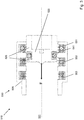
- FIG. 2 is a stator / working piston unit 400 of an implement, for example the one in FIG Fig. 1 working device 10 shown.
- the drive / working piston unit 400 is shown cut away along a working axis 401 and comprises a partially shown drive 410, a working piston 420 and a stator 430.
- the working piston 420 has a piston body 421 and a piston rod 422 and is provided for relative to move the stator 430 along the working axis 401.
- the drive 410 is provided to drive the working piston 420 along the working axis 401.
- the drive 410 comprises a piston coil capacitor (not shown) and one or more stator coil capacitors (not shown) and a piston coil 440 arranged on the working piston 420 and a plurality of stator coils 450 arranged on the stator.
- the piston coil 440 can be electrically connected to the piston coil capacitor in order to have a current flowing through it in the event of a rapid discharge of the piston coil capacitor and to generate a first magnetic field.
- the stator coils 450 can be electrically connected to the stator coil capacitor in order to have a current flowing through one stator coil capacitor in each case during a rapid discharge and to generate second magnetic fields which interact with the first magnetic field and cause repulsive forces between the piston coil 440 and one of the stator coils 450 in a timed manner and accelerate the working piston 420 along the working axis 401 out of the stator 430.
- Repulsive forces between the piston coil 440 and a respective stator coil 450 are brought about, for example, in that the magnetic field generated by the respective stator coil 450 is opposite to the magnetic field generated by the piston coil 440.
- the piston coil 440 and the stator coils 450 are preferably supplied with electrical current in opposite directions and one after the other by discharging the piston coil capacitor and the stator coil capacitor in a correspondingly timed manner, for example controlled by a control unit (not shown).
- the piston coil 440 and the stator coils 450 each have a piston coil axis and a stator coil axis, which coincide with the working axis 401 and are thus oriented parallel to one another.
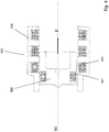
- Fig. 3 is a drive 510 of an implement, for example the one in Fig. 1 working device 10 shown.
- the drive 510 is shown cut open along a working axis 501 and is intended to drive a working piston 520 with a piston body and a piston rod (not shown) along the working axis 501 and to move it relative to a stator 530.
- the drive 510 comprises a piston coil 541 arranged on the working piston 520, a first stator coil 551 arranged on the stator 530, a second stator coil 552 arranged on the stator 530 and a third stator coil 553 arranged on the stator 530
- Piston coil capacitor can be connected in order to have current flowing through it in the event of a rapid discharge of the capacitor.
- a current flow through the piston coil 541 generates a first magnetic field.
- the stator coils 551, 552, 553 can each be electrically connected to a stator coil capacitor (not shown) in order to have a current flowing through them when the respective stator coil capacitor is rapidly discharged.
- a current flow through the stator coils 551, 552, 553 generates second magnetic fields.
- the piston coil 541 and the stator coils 551, 552, 553 each have a piston coil axis and a stator coil axis, which coincide with the working axis 501 and are thus oriented parallel to one another.
- the piston coil 541 and the stator coils 551, 552, 553 are wound in the same direction. In the exemplary embodiments not shown, the piston coil is wound in opposite directions relative to the stator coils.
- the piston coil 541 and the stator coils 551, 552, 553 preferably have in each case the same number of coil turns, so that the magnetic fields generated by the coils 541, 551, 552, 553 are essentially equally strong.
- the piston 520 preferably consists of a soft magnetic material such as iron or an alloy thereof, for example steel.
- the stator 530 has a stator frame 535, which preferably consists of a soft magnetic material, such as iron or an alloy thereof, for example steel.
- the stator frame 535 surrounds the stator coils 551, 552, 553 and extends in a circumferential direction with respect to the working axis 501. As a result, the magnetic fields generated by the stator coils 551, 552, 553 are strengthened in the area of the piston coil 541 and the accelerating force between the stator 530 and the working piston 520 is increased.
- the drive 510 is intended to move the working piston 520 from an in Fig. 3
- the starting position shown along the working axis 501 towards the ground towards the front (in Fig. 3 to the left).
- the piston coil 541 is partially immersed in the first stator coil 551 and is arranged offset to the front relative to the first stator coil.
- the coils 541, 551 are provided with circle symbols, a point in the circle representing a current flow out of the plane of the drawing and a cross in the circle representing a current flow into the plane of the drawing.
- the piston coil 541 and the first stator coil 551 are supplied with current in opposite directions and therefore generate opposing magnetic fields, so that the piston coil 541 is accelerated forward out of the first stator coil 551.
- the piston coil 541 and the second stator coil 552 are supplied with current in opposite directions, so that the piston coil 541 is accelerated even further forward out of the second stator coil 552 after the piston coil 541 has passed the first stator coil 551 was accelerated out.
- the piston coil 541 and the third stator coil 553 are supplied with current in opposite directions, so that the piston coil 541 is accelerated even further forward out of the third stator coil 553 after the piston coil 541 is off the second stator coil 552 was accelerated out.
- the piston coil 541 is accelerated forward three times in succession.
- the piston coil in the starting position is arranged offset to the rear relative to the first stator coil and the piston coil and the first stator coil are supplied with electrical current in the same direction, so that the piston coil is accelerated into the first stator coil.
- the piston coil 541 has a piston coil outside diameter which is greater than a Stator coil inside diameter of the first stator coil 551. While the working piston 520 moves forward, the piston coil 541 dips into the second stator coil 552 and completely through the second stator coil 552, as well as through the third stator coil 553.
- the working piston 520 has two reluctance elements 525 made of a soft magnetic material, which are designed as circumferential projections of the working piston 520.
- the reluctance elements 525 are each accelerated into the respective stator coil 551, 552, 553 by a magnetic field that is generated by one of the stator coils 551, 552, 553. This increases an overall forward acceleration of the working piston 520.
- Fig. 4 the working piston 520 and the stator 530 are shown in a first end position of the working piston 520 along the working axis 501.
- the piston coil 541 is arranged offset to the front relative to the third stator coil 553 along the working axis 501.
- FIG. 5 is an electrical circuit diagram of the in Fig. 3 Drive 510 shown.
- the drive 510 comprises a first capacitor 561, a second capacitor 562, a third capacitor 563, a switching circuit 570 with three free-wheeling diodes 590, a first switch 571, a second switch 572 and a third switch 573, a piston coil 541 arranged on the working piston, a first stator coil 551 arranged on the stator, a second stator coil 552 arranged on the stator and a third stator coil 553 arranged on the stator.
- the piston coil 541 can be electrically connected to each capacitor 561, 562, 563 in order to avoid rapid discharge of the respective capacitor 561 , 562, 563 to be flowed through with current, so that each of the capacitors 561, 562, 563 represents a piston coil capacitor.
- the stator coils 551, 552, 553 can also be electrically connected to one of the capacitors 561, 562, 563 in order to have a current flowing through them in the event of a rapid discharge of the respective capacitor 561, 562, 563, so that each of the capacitors 561, 562, 563 also has one Represents stator coil capacitor.
- the first capacitor 561 is electrically connected to an input of the first switch 571.
- An output of the first switch 571 is electrically connected to an input of the first stator coil 551, preferably hard-wired.
- An output of the first stator coil 551 is electrically connected, preferably hard-wired, to a first electrical stator contact 531 designed as a contact brush.
- the second capacitor 562 is electrically connected to an input of the second switch 572.
- An output of the second switch 572 is electrically connected to an input of the second stator coil 552, preferably hard-wired.
- An output of the second stator coil 552 is electrically connected, preferably hard-wired, to a second electrical stator contact 533 designed as a contact brush.
- the third capacitor 563 is electrically connected to an input of the third switch 573.
- An output of the third switch 573 is electrically connected to an input of the third stator coil 553, preferably hard-wired.
- An output of the third stator coil 553 is electrically connected to a third electrical stator contact 534 designed as a contact brush, preferably hard-wired.
- An input of the piston coil 541 is electrically connected, preferably permanently wired, to a first piston contact 544 which is designed as a contact bar and which the working piston has.
- the first piston contact 544 slides in an electrically conductive manner along the stator contacts 531, 533, 543 when the working piston moves along the working axis.
- One or more first springs (not shown) load the stator contacts 531, 533, 534 towards the first piston contact 544. In the case of exemplary embodiments that are not shown, a spring additionally or alternatively loads the first piston contact towards the first stator contact.
- An output of the piston coil 541 is electrically connected, preferably permanently wired, to a second piston contact 545 which is designed as a contact bar and which the working piston has.
- the second piston contact 545 slides in an electrically conductive manner along a ground contact 532 when the working piston moves along the working axis.
- the stator 530 has the ground contact 532, which is designed as a contact brush and is electrically connected to a ground potential, not shown, to which the capacitors 561, 562, 563 are also electrically connected.
- a second spring loads the ground contact 532 towards the second piston contact 545.
- a spring additionally or alternatively loads the second piston contact towards the ground contact.
- the piston contacts 544, 545 are rigid with the remaining working piston connected and move with the remaining working piston.
- the first and / or the second stator contact is designed as a slip ring.
- the respective rapid discharge of the capacitors 561, 562, 563 via the piston coil 541 and the stator coils 551, 552, 553 can be triggered by means of the circuit 570 by initially closing the first switch 571 when the first capacitor 561 is electrically charged and the first stator coil 551 and the piston coil 541 can be electrically connected to the first capacitor 561.
- the electric current then flows from the first capacitor 561 through the first switch 571, through the first stator coil 551, through the first stator contact 531 and the first piston contact 544, through the piston coil 541 and finally through the second piston contact 545 and the ground contact 532 to the first Capacitor 561.
- the second switch 572 is closed when the first capacitor 562 is electrically charged and the second stator coil 552 and the piston coil 541 are electrically connected to the second capacitor 562.
- the electric current then flows from the second capacitor 562 through the second switch 572, through the second stator coil 552, through the second stator contact 533 and the first piston contact 544, through the piston coil 541 and finally through the second piston contact 545 and the ground contact 532 to the second Capacitor 562.
- the third switch 573 is closed when the third capacitor 563 is electrically charged and the third stator coil 553 and the piston coil 541 are electrically connected to the third capacitor 563.
- the electrical current then flows from the third capacitor 563 through the third switch 573, through the third stator coil 553, through the third stator contact 534 and the first piston contact 544, through the piston coil 541 and finally through the second piston contact 545 and the ground contact 532 to the third Capacitor 563.
Landscapes
- Engineering & Computer Science (AREA)
- Power Engineering (AREA)
- Mechanical Engineering (AREA)
- Reciprocating, Oscillating Or Vibrating Motors (AREA)
- Portable Nailing Machines And Staplers (AREA)
Abstract
Arbeitsgerät zum Bearbeiten eines Untergrunds, insbesondere handgeführtes Arbeitsgerät, insbesondere Setzgerät zum Eintreiben von Befestigungselementen in den Untergrund, aufweisend einen Stator und einen Arbeitskolben, welcher dafür vorgesehen ist, sich relativ zu dem Stator entlang einer Arbeitsachse zu bewegen, weiterhin aufweisend einen Antrieb, welcher dafür vorgesehen ist, den Arbeitskolben entlang der Arbeitsachse von einer Startposition aus auf den Untergrund zu anzutreiben, wobei der Antrieb eine an dem Arbeitskolben angeordnete Kolbenspule und eine an dem Stator angeordnete erste Statorspule aufweist, und wobei die erste Kolbenspule dafür vorgesehen ist, während einer Bewegung des Arbeitskolbens relativ zu dem Stator entlang der Arbeitsachse in die erste Statorspule einzutauchen.Tool for working on a ground, in particular hand-held tool, in particular setting tool for driving fastening elements into the ground, having a stator and a working piston which is intended to move relative to the stator along a working axis, furthermore having a drive which for this purpose is provided to drive the working piston along the working axis from a starting position to the ground, the drive having a piston coil arranged on the working piston and a first stator coil arranged on the stator, and wherein the first piston coil is provided during a movement of the Working piston immerse into the first stator coil relative to the stator along the working axis.
Description
Die vorliegende Erfindung betrifft ein Arbeitsgerät, wie beispielsweise ein Setzgerät zum Eintreiben von Befestigungselementen in einen Untergrund.The present invention relates to a tool, such as a setting tool for driving fastening elements into a substrate.
Derartige Arbeitsgeräte weisen oft einen Arbeitskolben auf, welcher dafür vorgesehen ist, sich entlang einer Arbeitsachse zu bewegen. Angetrieben wird der Arbeitskolben von einem Antrieb, welcher den Arbeitskolben beschleunigt. Die
Setzgeräte weisen üblicherweise eine Aufnahme für ein Befestigungselement auf, aus welcher heraus ein darin aufgenommenes Befestigungselement entlang einer Arbeitsachse in den Untergrund befördert wird. Das Arbeitselement wird hierfür von dem Antrieb entlang der Arbeitsachse auf das Befestigungselement zu angetrieben. Aus der
Die Aufgabe der vorliegenden Erfindung liegt darin, ein Setzgerät der vorgenannten Art bereitzustellen, bei dem ein hoher Wirkungsgrad und/oder eine gute Setzqualität gewährleistet ist.The object of the present invention is to provide a setting tool of the aforementioned type in which a high degree of efficiency and / or a good setting quality is guaranteed.
Die Aufgabe ist gelöst bei einem vorzugsweise handgeführten Arbeitsgerät zum Bearbeiten eines Untergrunds, aufweisend einen Stator und einen Arbeitskolben, welcher dafür vorgesehen ist, sich relativ zu dem Stator entlang einer Arbeitsachse zu bewegen, weiterhin aufweisend einen Antrieb, welcher dafür vorgesehen ist, den Arbeitskolben von einer Startposition aus entlang der Arbeitsachse auf den Untergrund zu anzutreiben, wobei der Antrieb eine an dem Arbeitskolben angeordnete Kolbenspule und eine an dem Stator angeordnete erste Statorspule aufweist, und wobei die erste Kolbenspule dafür vorgesehen ist, während einer Bewegung des Arbeitskolbens relativ zu dem Stator entlang der Arbeitsachse in die erste Statorspule einzutauchen.The object is achieved in a preferably hand-held tool for working on a subsurface, having a stator and a working piston which is provided to move relative to the stator along a working axis, furthermore having a drive which is provided to drive the working piston from one Starting position to drive along the working axis to the ground, the drive having a piston coil arranged on the working piston and a first stator coil arranged on the stator, and the first piston coil being provided for during a movement of the working piston relative to the stator along the Working axis immerse in the first stator coil.
Eine vorteilhafte Ausgestaltung ist dadurch gekennzeichnet, dass die Kolbenspule eine Kolbenspulenachse aufweist und die erste Statorspule eine erste Statorspulenachse aufweist, welche parallel zur Kolbenspulenachse orientiert ist. Bevorzugt fällt die erste Statorspulenachse mit der Kolbenspulenachse zusammen. Ebenfalls bevorzugt sind die Kolbenspule und die erste Statorspule gleichsinnig mit Strom beaufschlagbar sind, um einander gleichgerichtete Magnetfelder zu erzeugen und die Kolbenspule in die erste Statorspule hinein zu beschleunigen. Besonders bevorzugt weist der Antrieb eine an dem Stator angeordnete zweite Statorspule auf, welche relativ zu der ersten Statorspule entlang der Arbeitsachse versetzt angeordnet ist und eine zweite Statorspulenachse aufweist, welche parallel zur Kolbenspulenachse orientiert ist, wobei die Kolbenspule und die zweite Statorspule gleichsinnig mit Strom beaufschlagbar sind, um einander gleichgerichtete Magnetfelder zu erzeugen und die Kolbenspule in die zweite Statorspule hinein zu beschleunigen, nachdem die Kolbenspule in die erste Statorspule hinein beschleunigt wurde. Die Kolbenspule wird dabei relativ zu der ersten Statorspule und relativ zu der zweiten Statorspule in die gleiche Richtung beschleunigt.An advantageous embodiment is characterized in that the piston coil has a piston coil axis and the first stator coil has a first stator coil axis which is oriented parallel to the piston coil axis. The first stator coil axis preferably coincides with the piston coil axis. It is also preferred that the piston coil and the first stator coil can be supplied with current in the same direction in order to generate magnetic fields in the same direction and to accelerate the piston coil into the first stator coil. The drive particularly preferably has a second stator coil arranged on the stator, which is arranged offset relative to the first stator coil along the working axis and has a second stator coil axis which is oriented parallel to the piston coil axis, with the piston coil and the second stator coil being able to be supplied with current in the same direction are to generate mutually rectified magnetic fields and to accelerate the piston coil into the second stator coil after the piston coil has been accelerated into the first stator coil. The piston coil is accelerated in the same direction relative to the first stator coil and relative to the second stator coil.
Eine vorteilhafte Ausgestaltung ist dadurch gekennzeichnet, dass die Kolbenspule und die erste Statorspule gegensinnig mit Strom beaufschlagbar sind, um einander entgegengesetzte Magnetfelder zu erzeugen und die Kolbenspule aus der ersten Statorspule heraus zu beschleunigen. Bevorzugt weist der Antrieb eine an dem Stator angeordnete zweite Statorspule auf, welche relativ zu der ersten Statorspule entlang der Arbeitsachse versetzt angeordnet ist und eine zweite Statorspulenachse aufweist, welche parallel zur Kolbenspulenachse orientiert ist, wobei die Kolbenspule und die zweite Statorspule gegensinnig mit Strom beaufschlagbar sind, um einander entgegengerichtete Magnetfelder zu erzeugen und die Kolbenspule aus der zweiten Statorspule heraus zu beschleunigen, nachdem die Kolbenspule aus der ersten Statorspule heraus beschleunigt wurde. Die Kolbenspule wird dabei relativ zu der ersten Statorspule und relativ zu der zweiten Statorspule in die gleiche Richtung beschleunigt. Bevorzugt sind die erste Statorspule und die zweite Statorspule relativ zueinander gleichsinnig gewickelt.An advantageous embodiment is characterized in that the piston coil and the first stator coil can be supplied with current in opposite directions in order to generate opposing magnetic fields and to accelerate the piston coil out of the first stator coil. The drive preferably has a second stator coil arranged on the stator, which is arranged offset relative to the first stator coil along the working axis and has a second stator coil axis which is oriented parallel to the piston coil axis, with the piston coil and the second stator coil being able to be supplied with current in opposite directions to generate opposing magnetic fields and to accelerate the piston coil out of the second stator coil after the piston coil has been accelerated out of the first stator coil. The piston coil is accelerated in the same direction relative to the first stator coil and relative to the second stator coil. The first stator coil and the second stator coil are preferably wound in the same direction relative to one another.
Eine vorteilhafte Ausgestaltung ist dadurch gekennzeichnet, dass der Antrieb einen ersten Kondensator aufweist, wobei die erste Statorspule und/oder die Kolbenspule elektrisch mit dem Kondensator verbindbar ist, um bei einer Schnellentladung des ersten Kondensators mit Strom durchflossen zu werden und das Magnetfeld zu erzeugen. Bevorzugt weist der Antrieb einen zweiten Kondensator auf, wobei die zweite Statorspule und/oder die Kolbenspule elektrisch mit dem zweiten Kondensator verbindbar ist, um bei einer Schnellentladung des zweiten Kondensators mit Strom durchflossen zu werden und das Magnetfeld zu erzeugen. Besonders bevorzugt umfasst das Arbeitsgerät eine Erfassungseinrichtung zum Erfassen einer Position des Arbeitskolbens und eine Steuereinrichtung zur Beaufschlagung der zweiten Statorspule mit elektrischem Strom in Abhängigkeit einer von der Erfassungseinrichtung erfassten Position des Arbeitskolbens.An advantageous embodiment is characterized in that the drive has a first capacitor, with the first stator coil and / or the piston coil electrically also can be connected to the capacitor in order to have current flowing through it in the event of a rapid discharge of the first capacitor and to generate the magnetic field. The drive preferably has a second capacitor, the second stator coil and / or the piston coil being electrically connectable to the second capacitor in order to have a current flowing through it in the event of a rapid discharge of the second capacitor and to generate the magnetic field. The working device particularly preferably comprises a detection device for detecting a position of the working piston and a control device for applying electrical current to the second stator coil as a function of a position of the working piston detected by the detection device.
Eine vorteilhafte Ausgestaltung ist dadurch gekennzeichnet, dass die Kolbenspule und die erste Statorspule elektrisch seriell miteinander verschaltet und relativ zueinander gleichsinnig oder gegensinnig gewickelt sind.An advantageous embodiment is characterized in that the piston coil and the first stator coil are electrically connected to one another in series and are wound in the same direction or in opposite directions relative to one another.
Eine vorteilhafte Ausgestaltung ist dadurch gekennzeichnet, dass die Kolbenspule einen Kolbenspulenaussendurchmesser aufweist, und wobei die erste Statorspule einen Statorspuleninnendurchmesser aufweist, welcher grösser ist als der Kolbenspulenaussendurchmesser.An advantageous embodiment is characterized in that the piston coil has a piston coil outside diameter, and the first stator coil has a stator coil inside diameter which is larger than the piston coil outside diameter.
Eine vorteilhafte Ausgestaltung ist dadurch gekennzeichnet, dass der Arbeitskolben ein Reluktanzelement aus einem weichmagnetischen Material, welches von dem Magnetfeld, das von der ersten Statorspule erzeugt wird, in die erste Statorspule hineinbeschleunigt wird. Bevorzugt springt das Reluktanzelement quer zur Arbeitsachse von dem übrigen Arbeitskolben auf die erste Statorspule zu vor.An advantageous embodiment is characterized in that the working piston is a reluctance element made of a soft magnetic material which is accelerated into the first stator coil by the magnetic field generated by the first stator coil. The reluctance element preferably projects transversely to the working axis from the rest of the working piston towards the first stator coil.
Eine vorteilhafte Ausgestaltung ist dadurch gekennzeichnet, dass das Arbeitsgerät als Setzgerät zum Eintreiben von Befestigungselementen in einen Untergrund ausgebildet ist, aufweisend eine Aufnahme, welche dafür vorgesehen ist, ein Befestigungselement aufzunehmen, wobei der Arbeitskolben oder der Stator dafür vorgesehen ist, ein in der Aufnahme aufgenommenes Befestigungselement entlang der Arbeitsachse in den Untergrund zu befördern, und wobei der Antrieb dafür vorgesehen ist, den Arbeitskolben entlang der Arbeitsachse auf das Befestigungselement zu anzutreiben.An advantageous embodiment is characterized in that the tool is designed as a setting tool for driving fastening elements into a substrate, having a receptacle which is provided for receiving a fastening element, the working piston or the stator being provided for a received in the receptacle To convey the fastening element into the ground along the working axis, and wherein the drive is provided to drive the working piston along the working axis onto the fastening element.
Unter einem Kondensator im Sinne der Erfindung ist ein elektrisches Bauelement zu verstehen, welches elektrische Ladung und die damit verbundene Energie in einem elektrischen Feld speichert. Insbesondere weist ein Kondensator zwei elektrisch leitende Elektroden auf, zwischen denen sich das elektrische Feld aufbaut, wenn die Elektroden elektrisch unterschiedlich geladen werden. Unter einem Befestigungselement im Sinne der Erfindung ist beispielsweise ein Nagel, ein Stift, eine Klammer, ein Clip, ein Bolzen, insbesondere Gewindebolzen oder dergleichen zu verstehen.A capacitor in the sense of the invention is to be understood as an electrical component which stores electrical charge and the associated energy in an electrical field. In particular, a capacitor has two electrically conductive electrodes, between which the electric field builds up when the electrodes are electrically charged differently. Under a fastener in the sense of The invention is to be understood as meaning, for example, a nail, a pin, a clamp, a clip, a bolt, in particular a threaded bolt or the like.
Unter einem weichmagnetischen Material im Sinne der Erfindung ist ein Material zu verstehen, welches eine hohe magnetische Sättigungsflussdichte und insbesondere eine kleine Koerzitivfeldstärke aufweist und somit ein das Material durchsetzendes Magnetfeld verstärkt. Insbesondere weist das weichmagnetische Material des Statorrahmens und/oder des Kolbenrahmens eine Sättigungsflussdichte von mindestens 1,0 T, bevorzugt mindestens 1,3 T, besonders bevorzugt mindestens 1,5 T, auf. Unter einem elektrisch leitenden Material im Sinne der Erfindung ist ein Material zu verstehen, welches eine hohe spezifische elektrische Leitfähigkeit aufweist, so dass ein das Material durchsetzendes Magnetfeld in dem Material Wirbelströme erzeugt. Ein weichmagnetisches und/oder elektrisch leitendes Material besteht bevorzugt aus einem ferromagnetischen Material, besonders bevorzugt aus einem ferromagnetischen Metall, beispielsweise Eisen, Kobalt, Nickel, oder einer Legierung mit einem oder mehreren ferromagnetischen Metallen als Hauptbestandteil.A soft magnetic material in the context of the invention is to be understood as a material which has a high magnetic saturation flux density and in particular a small coercive field strength and thus strengthens a magnetic field penetrating the material. In particular, the soft magnetic material of the stator frame and / or the piston frame has a saturation flux density of at least 1.0 T, preferably at least 1.3 T, particularly preferably at least 1.5 T. An electrically conductive material in the context of the invention is to be understood as a material which has a high specific electrical conductivity, so that a magnetic field penetrating the material generates eddy currents in the material. A soft magnetic and / or electrically conductive material preferably consists of a ferromagnetic material, particularly preferably a ferromagnetic metal, for example iron, cobalt, nickel, or an alloy with one or more ferromagnetic metals as the main component.
In den Zeichnungen ist die Erfindung in mehreren Ausführungsbeispielen dargestellt.The invention is illustrated in several exemplary embodiments in the drawings.
Es zeigen:
- Fig. 1
- ein Arbeitsgerät in einem Längsschnitt,
- Fig. 2
- eine Stator-Arbeitskolben-Einheit eines Arbeitsgeräts in einem perspektivischen Längsschnitt,
- Fig. 3
- eine Stator-Arbeitskolben-Einheit eines Arbeitsgeräts in einem Längsschnitt,
- Fig. 4
- eine Stator-Arbeitskolben-Einheit eines Arbeitsgeräts in einem Längsschnitt, und
- Fig. 5
- ein elektrisches Schaltdiagramm eines Antriebs.
- Fig. 1
- a working device in a longitudinal section,
- Fig. 2
- a stator / working piston unit of an implement in a perspective longitudinal section,
- Fig. 3
- a stator / working piston unit of an implement in a longitudinal section,
- Fig. 4
- a stator / working piston unit of an implement in a longitudinal section, and
- Fig. 5
- an electrical circuit diagram of a drive.
In
Das Arbeitsgerät 10 weist einen Arbeitskolben 60 auf, welcher einen Kolbenteller 70 und eine Kolbenstange 80 umfasst. Der Arbeitskolben 60 ist dafür vorgesehen, das Befestigungselement 30 aus der Aufnahme 20 heraus entlang der Arbeitsachse A in den Untergrund zu befördern. Hierbei ist der Arbeitskolben 60 mit seinem Kolbenteller 70 in einem Führungszylinder 95 entlang der Arbeitsachse A geführt. Bei nicht gezeigten Ausführungsbeispielen ist der Arbeitskolben von zwei, drei oder mehr Führungselementen, beispielsweise Führungsstangen entlang der Arbeitsachse geführt. Der Arbeitskolben 60 wird seinerseits von einem Antrieb 65 angetrieben, welcher einen Schaltkreislauf 200 und einen Kondensator 300 umfasst. Der Schaltkreislauf 200 ist dafür vorgesehen, eine elektrische Schnellentladung des zuvor aufgeladenen Kondensators 300 herbeizuführen und den dabei fliessenden Entladestrom dem Antrieb 65 zuzuführen.The
Das Arbeitsgerät 10 umfasst weiterhin ein Gehäuse 110, in welchem der Antrieb 65 aufgenommen ist, einen Griff 120 mit einem als Abzug ausgebildeten Betätigungselement 130, einen als Akkumulator ausgebildeten elektrischen Energiespeicher 140, eine Steuereinheit 150, einen Auslöseschalter 160, einen Anpressschalter 170, einen an dem Antrieb 65 angeordneten Temperatursensor 180 und elektrische Verbindungsleitungen 141, 161, 171, 181, 201, 301, welche die Steuereinheit 150 mit dem elektrischen Energiespeicher 140, dem Auslöseschalter 160, dem Anpressschalter 170, dem Temperatursensor 180, dem Schaltkreislauf 200 beziehungsweise dem Kondensator 300 verbinden. Bei nicht gezeigten Ausführungsbeispielen wird das Arbeitsgerät 10 anstelle des elektrischen Energiespeichers 140 oder zusätzlich zu dem elektrischen Energiespeicher 140 mittels eines Netzkabels mit elektrischer Energie versorgt. Die Steuereinheit umfasst elektronische Bauteile, vorzugsweise auf einer Platine miteinander zu einem oder mehreren Steuerstromkreisen verschaltet, insbesondere einen oder mehrere Mikroprozessoren.The
Wenn das Arbeitsgerät 10 an einen nicht gezeigten Untergrund (in
Wenn bei setzbereitem Arbeitsgerät 10 das Betätigungselement 130 betätigt wird, beispielsweise durch Ziehen mit dem Zeigefinger der Hand, welche den Griff 120 umgreift, betätigt das Betätigungselement 130 den Auslöseschalter 160, welcher dadurch mittels der Verbindungsleitung 161 ein Auslösesignal an die Steuereinheit 150 überträgt. Davon ausgelöst leitet die Steuereinheit 150 einen Kondensator-Entladevorgang ein, bei dem in dem Kondensator 300 gespeicherte elektrische Energie mittels des Schaltkreislaufs 200 von dem Kondensator 300 zu dem Antrieb 65 geleitet wird, indem der Kondensator 300 elektrisch entladen wird.When the
Der in
Zur Einleitung des Kondensator-Entladevorgangs schliesst die Steuereinheit 150 mittels der Verbindungsleitung 201 den Entladeschalter 230, wodurch ein Entladestrom des Kondensators 300 mit hoher Stromstärke durch den Antrieb 65 fliesst, welcher den Arbeitskolben 60 auf die Aufnahme 20 sowie das darin aufgenommene Befestigungselement 30 zu antreibt. Sobald die Kolbenstange 80 des Arbeitskolbens 60 auf einen nicht näher bezeichneten Kopf des Befestigungselements 30 trifft, wird das Befestigungselement 30 von dem Arbeitskolben 60 in den Untergrund eingetrieben. Überschüssige Bewegungsenergie des Arbeitskolbens 60 wird von einem Bremselement 85 aus einem federelastischen und/oder dämpfenden Material, beispielsweise Gummi oder einem Elastomer, aufgenommen, indem sich der Arbeitskolben 60 mit seinem Kolbenteller 70 gegen das Bremselement 85 bewegt und von diesem bis zu einem Stillstand abgebremst wird. Danach wird der Arbeitskolben 60 von einer nicht näher bezeichneten Rückstellvorrichtung in die setzbereite Position zurückgestellt.To initiate the capacitor discharge process, the
In
Die Kolbenspule 440 ist elektrisch mit dem Kolbenspulenkondensator verbindbar, um bei einer Schnellentladung des Kolbenspulenkondensators mit Strom durchflossen zu werden und ein erstes Magnetfeld zu erzeugen. Die Statorspulen 450 sind elektrisch mit den Statorspulenkondensator verbindbar, um bei einer Schnellentladung jeweils eines Statorspulenkondensators mit Strom durchflossen zu werden und zweite Magnetfelder zu erzeugen, welche mit dem ersten Magnetfeld wechselwirken und zeitlich aufeinander abgestimmt abstossende Kräfte zwischen der Kolbenspule 440 und jeweils einer der Statorspulen 450 bewirken und den Arbeitskolben 420 entlang der Arbeitsachse 401 aus dem Stator 430 heraus beschleunigen. Abstossende Kräfte zwischen der Kolbenspule 440 und jeweils einer Statorspule 450 werden beispielsweise dadurch bewirkt, dass das von der jeweiligen Statorspule 450 erzeugte Magnetfeld dem von der Kolbenspule 440 erzeugten Magnetfeld entgegengesetzt ist. Die Kolbenspule 440 und die Statorspulen 450 werden hierzu bevorzugt gegensinnig und zeitlich nacheinander mit elektrischem Strom beaufschlagt, indem der Kolbenspulenkondensator und die Statorspulenkondensatoren entsprechend zeitlich aufeinander abgestimmt entladen werden, beispielsweise von einer nicht gezeigten Steuereinheit gesteuert. Die Kolbenspule 440 und die Statorspulen 450 weisen jeweils eine Kolbenspulenachse beziehungsweise eine Statorspulenachse auf, welche mit der Arbeitsachse 401 zusammenfallen und somit parallel zueinander orientiert sind.The
In
Die Kolbenspule 541 und die Statorspulen 551, 552, 553 weisen jeweils eine Kolbenspulenachse beziehungsweise eine Statorspulenachse auf, welche mit der Arbeitsachse 501 zusammenfallen und somit parallel zueinander orientiert sind. Die Kolbenspule 541 und die Statorspulen 551, 552, 553 sind gleichsinnig gewickelt. Bei nicht gezeigten Ausführungsbeispielen ist die Kolbenspule relativ zu den Statorspulen gegensinnig gewickelt. Vorzugsweise weisen die Kolbenspule 541 und die Statorspulen 551, 552, 553 jeweils gleich viele Spulenwindungen auf, so dass die von den Spulen 541, 551, 552, 553 erzeugten Magnetfelder im Wesentlichen gleich stark sind.The
Bevorzugt besteht der Kolben 520 vorzugsweise aus einem weichmagnetischen Material, wie beispielsweise Eisen oder eine Legierung davon, beispielsweise Stahl. Der Stator 530 weist einen Statorrahmen 535 auf, welcher vorzugsweise aus einem weichmagnetischen Material besteht, wie beispielsweise Eisen oder eine Legierung davon, beispielsweise Stahl. Der Statorrahmen 535 umgibt die Statorspulen 551, 552, 553 und erstreckt sich bezüglich der Arbeitsachse 501 in einer umlaufenden Richtung. Dadurch werden die von den Statorspulen 551, 552, 553 erzeugten Magnetfelder im Bereich der Kolbenspule 541 verstärkt und die beschleunigende Kraft zwischen dem Stator 530 und dem Arbeitskolben 520 erhöht.The
Der Antrieb 510 ist dafür vorgesehen, den Arbeitskolben 520 von einer in
Insgesamt wird die Kolbenspule 541 dreimal nacheinander nach vorne beschleunigt. Bei nicht gezeigten Ausführungsbeispielen ist die Kolbenspule in der Startposition relativ zu der ersten Statorspule nach hinten versetzt angeordnet und die Kolbenspule und die erste Statorspule werden gleichsinnig mit elektrischem Strom beaufschlagt, so dass die Kolbenspule in die erste Statorspule hinein beschleunigt wird. Die Kolbenspule 541 weist einen Kolbenspulenaussendurchmesser auf, welcher grösser ist als ein Statorspuleninnendurchmesser der ersten Statorspule 551. Während sich der Arbeitskolben 520 nach vorne bewegt, taucht die Kolbenspule 541 in die zweite Statorspule 552 ein und vollständig durch die zweite Statorspule 552 hindurch, ebenso durch die dritte Statorspule 553.In total, the
Der Arbeitskolben 520 weist zwei Reluktanzelemente 525 aus einem weichmagnetischen Material auf, welche als umlaufende Vorsprünge des Arbeitskolbens 520 ausgebildet sind. In der in
Durch das Eintauchen der Kolbenspulen 541, 542, 543 findet eine Kraftübertragung über eine relativ lange Zeit und/oder einen relativ langen Weg des Arbeitskolbens 520 statt, so dass eine relativ kleine Maximalkraft für eine ausreichende Energieübertragung erforderlich ist. Dadurch sind mechanische Belastungen auf sämtliche Bauteile des Antriebs 510 reduziert. Ausserdem ist ein relativ kleiner Maximalstrom erforderlich. Darüber hinaus wird entstehende Abwärme auf mehrere Spulen verteilt, was eine Kühlung des Antriebs 519 erleichtert.As a result of the immersion of the piston coils 541, 542, 543, a power transmission takes place over a relatively long time and / or a relatively long path of the working
In
In
Der erste Kondensator 561 ist mit einem Eingang des ersten Schalters 571 elektrisch verbunden. Ein Ausgang des ersten Schalters 571 ist mit einem Eingang der ersten Statorspule 551 elektrisch verbunden, bevorzugt fest verdrahtet. Ein Ausgang der ersten Statorspule 551 ist mit einem als Kontaktbürste ausgebildeten ersten elektrischen Statorkontakt 531 elektrisch verbunden, bevorzugt fest verdrahtet. Der zweite Kondensator 562 ist mit einem Eingang des zweiten Schalters 572 elektrisch verbunden. Ein Ausgang des zweiten Schalters 572 ist mit einem Eingang der zweiten Statorspule 552 elektrisch verbunden, bevorzugt fest verdrahtet. Ein Ausgang der zweiten Statorspule 552 ist mit einem als Kontaktbürste ausgebildeten zweiten elektrischen Statorkontakt 533 elektrisch verbunden, bevorzugt fest verdrahtet. Der dritte Kondensator 563 ist mit einem Eingang des dritten Schalters 573 elektrisch verbunden. Ein Ausgang des dritten Schalters 573 ist mit einem Eingang der dritten Statorspule 553 elektrisch verbunden, bevorzugt fest verdrahtet. Ein Ausgang der dritten Statorspule 553 ist mit einem als Kontaktbürste ausgebildeten dritten elektrischen Statorkontakt 534 elektrisch verbunden, bevorzugt fest verdrahtet.The
Ein Eingang der Kolbenspule 541 ist mit einem als Kontaktschiene ausgebildeten ersten Kolbenkontakt 544, welchen der Arbeitskolben aufweist, elektrisch verbunden, bevorzugt fest verdrahtet. Der erste Kolbenkontakt 544 gleitet elektrisch leitend an den Statorkontakten 531, 533, 543 entlang, wenn sich der Arbeitskolben entlang der Arbeitsachse bewegt. Eine oder mehrere nicht gezeigte erste Federn belasten die Statorkontakte 531, 533, 534 auf den ersten Kolbenkontakt 544 zu. Bei nicht gezeigten Ausführungsbeispielen belastet eine Feder zusätzlich oder alternativ den ersten Kolbenkontakt auf den ersten Statorkontakt zu. Ein Ausgang der Kolbenspule 541 ist mit einem als Kontaktschiene ausgebildeten zweiten Kolbenkontakt 545, welchen der Arbeitskolben aufweist, elektrisch verbunden, bevorzugt fest verdrahtet. Der zweite Kolbenkontakt 545 gleitet elektrisch leitend an einem Massekontakt 532 entlang, wenn sich der Arbeitskolben entlang der Arbeitsachse bewegt. Der Stator 530 weist den Massekontakt 532 auf, welcher als Kontaktbürste ausgebildet und mit einem nicht gezeigten Massepotential elektrisch verbunden ist, mit welchem auch die Kondensatoren 561, 562, 563 elektrisch verbunden sind. Eine nicht gezeigte zweite Feder belastet den Massekontakt 532 auf den zweiten Kolbenkontakt 545 zu. Bei nicht gezeigten Ausführungsbeispielen belastet eine Feder zusätzlich oder alternativ den zweiten Kolbenkontakt auf den Massekontakt zu. Die Kolbenkontakte 544, 545 sind starr mit dem übrigen Arbeitskolben verbunden und bewegen sich mit dem übrigen Arbeitskolben mit. Bei nicht gezeigten Ausführungsbeispielen ist der erste und/oder der zweite Statorkontakt als Schleifring ausgebildet.An input of the
Die jeweilige Schnellentladung der Kondensatoren 561, 562, 563 über die Kolbenspule 541 und die Statorspulen 551, 552, 553 ist mittels des Schaltkreislaufs 570 auslösbar, indem zunächst der erste Schalter 571 bei elektrisch aufgeladenem ersten Kondensator 561 geschlossen und die erste Statorspule 551 sowie die Kolbenspule 541 elektrisch mit dem ersten Kondensator 561 verbunden werden. Der elektrische Strom fliesst dann von dem ersten Kondensator 561 durch den ersten Schalter 571, durch die erste Statorspule 551, durch den ersten Statorkontakt 531 und den ersten Kolbenkontakt 544, durch die Kolbenspule 541 und schliesslich durch den zweiten Kolbenkontakt 545 und den Massekontakt 532 zum ersten Kondensator 561. Sobald die Kolbenspule 541 vollständig in die zweite Statorspule 552 eingetaucht ist, werden der zweite Schalter 572 bei elektrisch aufgeladenem ersten Kondensator 562 geschlossen und die zweite Statorspule 552 sowie die Kolbenspule 541 elektrisch mit dem zweiten Kondensator 562 verbunden. Der elektrische Strom fliesst dann von dem zweiten Kondensator 562 durch den zweiten Schalter 572, durch die zweite Statorspule 552, durch den zweiten Statorkontakt 533 und den ersten Kolbenkontakt 544, durch die Kolbenspule 541 und schliesslich durch den zweiten Kolbenkontakt 545 und den Massekontakt 532 zum zweiten Kondensator 562. Sobald die Kolbenspule 541 vollständig in die dritte Statorspule 553 eingetaucht ist, werden der dritte Schalter 573 bei elektrisch aufgeladenem dritten Kondensator 563 geschlossen und die dritte Statorspule 553 sowie die Kolbenspule 541 elektrisch mit dem dritten Kondensator 563 verbunden. Der elektrische Strom fliesst dann von dem dritten Kondensator 563 durch den dritten Schalter 573, durch die dritte Statorspule 553, durch den dritten Statorkontakt 534 und den ersten Kolbenkontakt 544, durch die Kolbenspule 541 und schliesslich durch den zweiten Kolbenkontakt 545 und den Massekontakt 532 zum dritten Kondensator 563.The respective rapid discharge of the
Die Erfindung wurde anhand einer Reihe von in den Zeichnungen dargestellten und nicht dargestellten Ausführungsbeispielen beschrieben. Die einzelnen Merkmale der verschiedenen Ausführungsbeispiele sind einzeln oder in beliebiger Kombination miteinander anwendbar, soweit sie sich nicht widersprechen. Es wird darauf hingewiesen, dass das erfindungsgemässe Arbeitsgerät auch für andere Anwendungen einsetzbar ist, beispielsweise als Bohrhammer oder dergleichen.The invention has been described on the basis of a number of exemplary embodiments shown in the drawings and not shown. The individual features of the various exemplary embodiments can be used individually or in any combination with one another, provided they do not contradict one another. It is pointed out that the working device according to the invention can also be used for other applications, for example as a hammer drill or the like.
Claims (15)
Priority Applications (7)
| Application Number | Priority Date | Filing Date | Title |
|---|---|---|---|
| EP19218901.7A EP3838493A1 (en) | 2019-12-20 | 2019-12-20 | Working implement |
| PCT/EP2020/085440 WO2021122270A1 (en) | 2019-12-20 | 2020-12-10 | Working tool |
| JP2022535973A JP7449386B2 (en) | 2019-12-20 | 2020-12-10 | actuation tool |
| AU2020410228A AU2020410228A1 (en) | 2019-12-20 | 2020-12-10 | Working tool |
| US17/782,041 US20230001555A1 (en) | 2019-12-20 | 2020-12-10 | Working tool |
| CN202080085946.6A CN114786878A (en) | 2019-12-20 | 2020-12-10 | Working tool |
| EP20819794.7A EP4076851B1 (en) | 2019-12-20 | 2020-12-10 | Working implement |
Applications Claiming Priority (1)
| Application Number | Priority Date | Filing Date | Title |
|---|---|---|---|
| EP19218901.7A EP3838493A1 (en) | 2019-12-20 | 2019-12-20 | Working implement |
Publications (1)
| Publication Number | Publication Date |
|---|---|
| EP3838493A1 true EP3838493A1 (en) | 2021-06-23 |
Family
ID=69005348
Family Applications (2)
| Application Number | Title | Priority Date | Filing Date |
|---|---|---|---|
| EP19218901.7A Withdrawn EP3838493A1 (en) | 2019-12-20 | 2019-12-20 | Working implement |
| EP20819794.7A Active EP4076851B1 (en) | 2019-12-20 | 2020-12-10 | Working implement |
Family Applications After (1)
| Application Number | Title | Priority Date | Filing Date |
|---|---|---|---|
| EP20819794.7A Active EP4076851B1 (en) | 2019-12-20 | 2020-12-10 | Working implement |
Country Status (6)
| Country | Link |
|---|---|
| US (1) | US20230001555A1 (en) |
| EP (2) | EP3838493A1 (en) |
| JP (1) | JP7449386B2 (en) |
| CN (1) | CN114786878A (en) |
| AU (1) | AU2020410228A1 (en) |
| WO (1) | WO2021122270A1 (en) |
Cited By (1)
| Publication number | Priority date | Publication date | Assignee | Title |
|---|---|---|---|---|
| WO2023038926A1 (en) * | 2021-09-08 | 2023-03-16 | Illinois Tool Works Inc. | Electroportable device |
Families Citing this family (2)
| Publication number | Priority date | Publication date | Assignee | Title |
|---|---|---|---|---|
| US12053869B2 (en) * | 2021-04-07 | 2024-08-06 | Stanley Fastening Systems, L.P. | Multistage solenoid fastener device with magnetic driver |
| WO2023285307A1 (en) | 2021-07-10 | 2023-01-19 | Rhefor Gbr | Setting tool |
Citations (4)
| Publication number | Priority date | Publication date | Assignee | Title |
|---|---|---|---|---|
| US6830173B2 (en) | 2000-08-25 | 2004-12-14 | Senco Products, Inc. | Impact device |
| WO2018104406A1 (en) | 2016-12-06 | 2018-06-14 | Hilti Aktiengesellschaft | Electrodynamic drive |
| WO2019211264A1 (en) * | 2018-05-01 | 2019-11-07 | Rhefor Gbr | Hand-held nail gun and drive |
| WO2019233845A1 (en) * | 2018-06-06 | 2019-12-12 | Hilti Aktiengesellschaft | Setting tool |
Family Cites Families (20)
| Publication number | Priority date | Publication date | Assignee | Title |
|---|---|---|---|---|
| US3486095A (en) * | 1965-05-06 | 1969-12-23 | Westinghouse Electric Corp | Cycle control for linear motion device |
| US3778697A (en) * | 1971-04-26 | 1973-12-11 | Arkon Scient Labor | Solenoid actuators and generators and method of using same |
| US3924789A (en) * | 1973-06-07 | 1975-12-09 | Duo Fast Corp | Electric fastener driving tool |
| US4183453A (en) * | 1977-04-10 | 1980-01-15 | Swingline, Inc. | Electronically operated portable fastener driving tool |
| US4293088A (en) * | 1979-10-12 | 1981-10-06 | Swingline Inc. | Electronically operated portable fastener driving tool |
| JPH06101994A (en) * | 1992-09-22 | 1994-04-12 | Japan Steel Works Ltd:The | Coil gun |
| JPH09196597A (en) * | 1996-01-11 | 1997-07-31 | Japan Steel Works Ltd:The | Electromagnetic accelerator |
| US5760552A (en) * | 1996-10-23 | 1998-06-02 | Regitar Power Co., Ltd. | Method of controlling driving power of double-solenoid electric percussion tools |
| US6796477B2 (en) * | 2002-10-30 | 2004-09-28 | Aplus Pneumatic Corp. | Nail-hammering apparatus |
| US6854530B1 (en) * | 2003-09-01 | 2005-02-15 | Chih Hao Yiu | Method for driving electric percussion tool |
| US6857549B1 (en) * | 2003-11-21 | 2005-02-22 | Navtor Technology Corporation | Nail driving gun with a shock-absorbing member |
| US7503400B2 (en) * | 2004-01-30 | 2009-03-17 | Arrow Fastener Co., Inc. | Two shot power nailer |
| JP4556485B2 (en) * | 2004-05-18 | 2010-10-06 | 日立工機株式会社 | Battery operated tool |
| US20070246015A1 (en) * | 2006-04-19 | 2007-10-25 | Alejandro Moreno | Solenoid-operated valve with coil for sensing plunger position |
| US7537145B2 (en) * | 2007-02-01 | 2009-05-26 | Black & Decker Inc. | Multistage solenoid fastening device |
| US8162073B2 (en) * | 2009-02-20 | 2012-04-24 | Robert Bosch Gmbh | Nailer with brushless DC motor |
| US20130334277A1 (en) * | 2011-02-28 | 2013-12-19 | Hitachi Koki Co., Ltd. | Electric tool and method of driving electric tool |
| DE102013218060A1 (en) * | 2012-12-06 | 2014-06-12 | Robert Bosch Gmbh | Linear drive and piston pump arrangement |
| US10723005B2 (en) * | 2018-03-28 | 2020-07-28 | Black & Decker Inc. | Electric fastener driving tool assembly including a driver home position sensor |
| EP3578307A1 (en) * | 2018-06-06 | 2019-12-11 | HILTI Aktiengesellschaft | Setting device |
-
2019
- 2019-12-20 EP EP19218901.7A patent/EP3838493A1/en not_active Withdrawn
-
2020
- 2020-12-10 AU AU2020410228A patent/AU2020410228A1/en active Pending
- 2020-12-10 JP JP2022535973A patent/JP7449386B2/en active Active
- 2020-12-10 CN CN202080085946.6A patent/CN114786878A/en active Pending
- 2020-12-10 US US17/782,041 patent/US20230001555A1/en active Pending
- 2020-12-10 EP EP20819794.7A patent/EP4076851B1/en active Active
- 2020-12-10 WO PCT/EP2020/085440 patent/WO2021122270A1/en unknown
Patent Citations (4)
| Publication number | Priority date | Publication date | Assignee | Title |
|---|---|---|---|---|
| US6830173B2 (en) | 2000-08-25 | 2004-12-14 | Senco Products, Inc. | Impact device |
| WO2018104406A1 (en) | 2016-12-06 | 2018-06-14 | Hilti Aktiengesellschaft | Electrodynamic drive |
| WO2019211264A1 (en) * | 2018-05-01 | 2019-11-07 | Rhefor Gbr | Hand-held nail gun and drive |
| WO2019233845A1 (en) * | 2018-06-06 | 2019-12-12 | Hilti Aktiengesellschaft | Setting tool |
Cited By (1)
| Publication number | Priority date | Publication date | Assignee | Title |
|---|---|---|---|---|
| WO2023038926A1 (en) * | 2021-09-08 | 2023-03-16 | Illinois Tool Works Inc. | Electroportable device |
Also Published As
| Publication number | Publication date |
|---|---|
| US20230001555A1 (en) | 2023-01-05 |
| EP4076851A1 (en) | 2022-10-26 |
| CN114786878A (en) | 2022-07-22 |
| WO2021122270A1 (en) | 2021-06-24 |
| EP4076851B1 (en) | 2024-05-22 |
| AU2020410228A1 (en) | 2022-07-14 |
| EP4076851C0 (en) | 2024-05-22 |
| JP2023507721A (en) | 2023-02-27 |
| JP7449386B2 (en) | 2024-03-13 |
Similar Documents
| Publication | Publication Date | Title |
|---|---|---|
| EP4076851B1 (en) | Working implement | |
| EP4076853A1 (en) | Working tool | |
| EP3578309A1 (en) | Setting device | |
| EP3801989B1 (en) | Setting device | |
| EP3898120B1 (en) | Bolt pushing device and method for operating same | |
| EP3801993B1 (en) | Setting device | |
| EP3801990B1 (en) | Setting device | |
| EP4076849B1 (en) | Working implement | |
| EP4076855B1 (en) | Working implement | |
| EP3801997A1 (en) | Setting tool | |
| EP3578306A1 (en) | Setting device | |
| EP4076850B1 (en) | Working implement | |
| EP3578312A1 (en) | Setting device | |
| EP3801996A1 (en) | Fastener driving tool | |
| EP4076852A1 (en) | Working tool | |
| EP4076854B1 (en) | Working implement | |
| DE2537815C2 (en) | Method and apparatus for inserting a bolt with an interference fit into a bore |
Legal Events
| Date | Code | Title | Description |
|---|---|---|---|
| PUAI | Public reference made under article 153(3) epc to a published international application that has entered the european phase |
Free format text: ORIGINAL CODE: 0009012 |
|
| STAA | Information on the status of an ep patent application or granted ep patent |
Free format text: STATUS: THE APPLICATION HAS BEEN PUBLISHED |
|
| AK | Designated contracting states |
Kind code of ref document: A1 Designated state(s): AL AT BE BG CH CY CZ DE DK EE ES FI FR GB GR HR HU IE IS IT LI LT LU LV MC MK MT NL NO PL PT RO RS SE SI SK SM TR |
|
| STAA | Information on the status of an ep patent application or granted ep patent |
Free format text: STATUS: THE APPLICATION IS DEEMED TO BE WITHDRAWN |
|
| 18D | Application deemed to be withdrawn |
Effective date: 20211224 |