EP3838397B1 - Four reformeur et son utilisation pour le reformage à la vapeur - Google Patents
Four reformeur et son utilisation pour le reformage à la vapeur Download PDFInfo
- Publication number
- EP3838397B1 EP3838397B1 EP19020710.0A EP19020710A EP3838397B1 EP 3838397 B1 EP3838397 B1 EP 3838397B1 EP 19020710 A EP19020710 A EP 19020710A EP 3838397 B1 EP3838397 B1 EP 3838397B1
- Authority
- EP
- European Patent Office
- Prior art keywords
- reformer
- rows
- burner
- main carrier
- row
- Prior art date
- Legal status (The legal status is an assumption and is not a legal conclusion. Google has not performed a legal analysis and makes no representation as to the accuracy of the status listed.)
- Active
Links
Images


Classifications
-
- B—PERFORMING OPERATIONS; TRANSPORTING
- B01—PHYSICAL OR CHEMICAL PROCESSES OR APPARATUS IN GENERAL
- B01J—CHEMICAL OR PHYSICAL PROCESSES, e.g. CATALYSIS OR COLLOID CHEMISTRY; THEIR RELEVANT APPARATUS
- B01J19/00—Chemical, physical or physico-chemical processes in general; Their relevant apparatus
- B01J19/24—Stationary reactors without moving elements inside
- B01J19/2415—Tubular reactors
- B01J19/2425—Tubular reactors in parallel
-
- B—PERFORMING OPERATIONS; TRANSPORTING
- B01—PHYSICAL OR CHEMICAL PROCESSES OR APPARATUS IN GENERAL
- B01J—CHEMICAL OR PHYSICAL PROCESSES, e.g. CATALYSIS OR COLLOID CHEMISTRY; THEIR RELEVANT APPARATUS
- B01J19/00—Chemical, physical or physico-chemical processes in general; Their relevant apparatus
- B01J19/24—Stationary reactors without moving elements inside
- B01J19/248—Reactors comprising multiple separated flow channels
-
- B—PERFORMING OPERATIONS; TRANSPORTING
- B01—PHYSICAL OR CHEMICAL PROCESSES OR APPARATUS IN GENERAL
- B01J—CHEMICAL OR PHYSICAL PROCESSES, e.g. CATALYSIS OR COLLOID CHEMISTRY; THEIR RELEVANT APPARATUS
- B01J8/00—Chemical or physical processes in general, conducted in the presence of fluids and solid particles; Apparatus for such processes
- B01J8/02—Chemical or physical processes in general, conducted in the presence of fluids and solid particles; Apparatus for such processes with stationary particles, e.g. in fixed beds
- B01J8/06—Chemical or physical processes in general, conducted in the presence of fluids and solid particles; Apparatus for such processes with stationary particles, e.g. in fixed beds in tube reactors; the solid particles being arranged in tubes
- B01J8/062—Chemical or physical processes in general, conducted in the presence of fluids and solid particles; Apparatus for such processes with stationary particles, e.g. in fixed beds in tube reactors; the solid particles being arranged in tubes being installed in a furnace
-
- B—PERFORMING OPERATIONS; TRANSPORTING
- B01—PHYSICAL OR CHEMICAL PROCESSES OR APPARATUS IN GENERAL
- B01J—CHEMICAL OR PHYSICAL PROCESSES, e.g. CATALYSIS OR COLLOID CHEMISTRY; THEIR RELEVANT APPARATUS
- B01J8/00—Chemical or physical processes in general, conducted in the presence of fluids and solid particles; Apparatus for such processes
- B01J8/02—Chemical or physical processes in general, conducted in the presence of fluids and solid particles; Apparatus for such processes with stationary particles, e.g. in fixed beds
- B01J8/06—Chemical or physical processes in general, conducted in the presence of fluids and solid particles; Apparatus for such processes with stationary particles, e.g. in fixed beds in tube reactors; the solid particles being arranged in tubes
- B01J8/065—Feeding reactive fluids
-
- B—PERFORMING OPERATIONS; TRANSPORTING
- B01—PHYSICAL OR CHEMICAL PROCESSES OR APPARATUS IN GENERAL
- B01J—CHEMICAL OR PHYSICAL PROCESSES, e.g. CATALYSIS OR COLLOID CHEMISTRY; THEIR RELEVANT APPARATUS
- B01J8/00—Chemical or physical processes in general, conducted in the presence of fluids and solid particles; Apparatus for such processes
- B01J8/02—Chemical or physical processes in general, conducted in the presence of fluids and solid particles; Apparatus for such processes with stationary particles, e.g. in fixed beds
- B01J8/06—Chemical or physical processes in general, conducted in the presence of fluids and solid particles; Apparatus for such processes with stationary particles, e.g. in fixed beds in tube reactors; the solid particles being arranged in tubes
- B01J8/067—Heating or cooling the reactor
-
- B—PERFORMING OPERATIONS; TRANSPORTING
- B01—PHYSICAL OR CHEMICAL PROCESSES OR APPARATUS IN GENERAL
- B01J—CHEMICAL OR PHYSICAL PROCESSES, e.g. CATALYSIS OR COLLOID CHEMISTRY; THEIR RELEVANT APPARATUS
- B01J2208/00—Processes carried out in the presence of solid particles; Reactors therefor
- B01J2208/00008—Controlling the process
- B01J2208/00017—Controlling the temperature
- B01J2208/00504—Controlling the temperature by means of a burner
-
- B—PERFORMING OPERATIONS; TRANSPORTING
- B01—PHYSICAL OR CHEMICAL PROCESSES OR APPARATUS IN GENERAL
- B01J—CHEMICAL OR PHYSICAL PROCESSES, e.g. CATALYSIS OR COLLOID CHEMISTRY; THEIR RELEVANT APPARATUS
- B01J2219/00—Chemical, physical or physico-chemical processes in general; Their relevant apparatus
- B01J2219/00002—Chemical plants
- B01J2219/00018—Construction aspects
- B01J2219/0002—Plants assembled from modules joined together
-
- B—PERFORMING OPERATIONS; TRANSPORTING
- B01—PHYSICAL OR CHEMICAL PROCESSES OR APPARATUS IN GENERAL
- B01J—CHEMICAL OR PHYSICAL PROCESSES, e.g. CATALYSIS OR COLLOID CHEMISTRY; THEIR RELEVANT APPARATUS
- B01J2219/00—Chemical, physical or physico-chemical processes in general; Their relevant apparatus
- B01J2219/00049—Controlling or regulating processes
- B01J2219/00051—Controlling the temperature
- B01J2219/00157—Controlling the temperature by means of a burner
-
- B—PERFORMING OPERATIONS; TRANSPORTING
- B01—PHYSICAL OR CHEMICAL PROCESSES OR APPARATUS IN GENERAL
- B01J—CHEMICAL OR PHYSICAL PROCESSES, e.g. CATALYSIS OR COLLOID CHEMISTRY; THEIR RELEVANT APPARATUS
- B01J2219/00—Chemical, physical or physico-chemical processes in general; Their relevant apparatus
- B01J2219/32—Details relating to packing elements in the form of grids or built-up elements for forming a unit of module inside the apparatus for mass or heat transfer
- B01J2219/322—Basic shape of the elements
- B01J2219/32279—Tubes or cylinders
Definitions
- the invention relates to a reformer furnace for the catalytic reforming of a carbon-containing feedstock with steam, wherein the reformer furnace comprises a radiation chamber defined by a plurality of walls and separated from the external environment, and the radiation chamber has a steel structure designed as a framework for fastening inlet and outlet pipes, burners and vertically arranged reformer tubes.
- Reformer furnaces for the catalytic reforming of carbonaceous feedstocks with steam are known in a variety of designs.
- a well-known example of a reformer furnace for the catalytic reforming of carbonaceous feedstocks is the steam reformer for reforming natural gas and steam to produce synthesis gas, a mixture of carbon monoxide and hydrogen, and often also undesirable accompanying substances such as carbon dioxide.
- Such reforming processes are endothermic and slow, so that an external source of heat is required to heat the catalyst-filled reformer tubes (also known as reaction tubes) of the reformer furnace in order to convert the carbonaceous feedstock with steam.
- Each row of reformer tubes is usually fired by two rows of burners, with one row of reformer tubes being arranged centrally between two rows of burners running parallel to the rows of reformer tubes to ensure that the reformer tubes are evenly fired.
- a distinction is made between wall-mounted burner rows and non-wall-mounted burner rows. In wall-mounted burner rows, the burners are arranged between a wall of the reformer furnace and a row of reformer tubes. In non-wall-mounted burner rows, the burners are arranged between two rows of reformer tubes.
- the burners are arranged within the so-called firing chamber of the reformer furnace.
- the feed gas supply and the product gas discharge to and from the reformer tubes necessarily take place outside the firing chamber, so that the walls of the reformer tubes define the spatial separation between the reaction chamber and the firing chamber.
- the entirety of the firing chamber and reformer tubes is also called the radiation zone of the reformer furnace.
- the burners of the burner rows are supplied with air and fuel gas via supply lines and are arranged in the most common designs either in the ceiling or in the floor of the reformer furnace, with the burner flames directed vertically downwards to the reformer furnace floor or vertically upwards to the reformer furnace ceiling.
- Other arrangements of the burners such as on the Side walls of the reformer furnace for lateral firing, or a terraced arrangement for diagonal firing, are also known, but are used less frequently.
- the ceiling of the radiation room is basically designed as a self-supporting or suspended steel structure, since vertically arranged supports (e.g. pillars) for carrying loads cannot be led through the firing room.
- the main support units of the steel structure consisting of vertical supports and horizontal main beams, are therefore arranged in such a way that the supports run flush with the wall and outside the firing room.
- the side length of the reformer furnace is defined by the length of the reformer tube rows and the burner rows, i.e. by the number of reformer tubes and burners per reformer tube row or burner row. If the side length of the reformer furnace exceeds a certain amount (for example 6 to 7 meters), static limitations require more than two main support units arranged on the front sides of the reformer furnace to carry the loads caused by the longer burner rows and reformer tube rows. In this case, a third main support unit or, if necessary, further main support units must be arranged between the main support units arranged on the front sides. The distance from main support unit to main support unit is essentially the same in each case, and the burner rows and reformer tube rows run orthogonally to the main supports of a main support unit running horizontally on the ceiling of the radiation room.
- the aforementioned way of arranging the main support units also has disadvantages. Due to the additional main support units not arranged on the front sides of the reformer furnace, i.e. due to the increase in the number of main support units in large reformer furnaces to three or more, the main supports of the main support units running horizontally along the ceiling do not run along the wall but rather centrally through the radiation chamber of the reformer furnace. A centrally running main support requires a larger reformer tube center distance at this point. In other words, the distance from one reformer tube to the adjacent reformer tube in a row of reformer tubes must be increased at the point where the main support of the main support unit runs along the ceiling of the radiation chamber.
- the ideal reformer tube center distance in a standard reformer furnace is approximately 300 mm from reformer tube to reformer tube. In the area of a centrally running main beam, this reformer tube center distance must be increased to more than 500 mm.
- This design limitation means that the reformer tubes in the area of the main support axes have higher operating temperatures, which generally leads to a reduced service life of the reformer tube and results in higher safety margins in the design of the reformer furnace.
- the higher temperature on these reformer tubes is caused by the fact that the visibility factor to the burner flames is greater than on the other reformer tubes that are located within a reformer tube row and where the reformer tube axis distances are smaller.
- the US 2019/0321800 A1 discloses a box-shaped reformer furnace which can be divided into several sections.
- the upper ends of the reformer tubes are flexibly mounted on a support structure located above the reformer, which comprises support arms.
- the support arms are connected in two adjacent rows, each with a reactor tube.
- Each of the support arms is supported by a horizontal beam through a spring arrangement.
- the object of the present invention is to at least partially overcome the aforementioned disadvantages of the prior art.
- Another object of the present invention is to provide a reformer furnace which does not include bays.
- Another object of the present invention is to provide a reformer furnace in which the reformer tubes have more uniform operating temperatures than is the case in known reformer furnaces.
- the horizontally running main supports of the main support units are arranged parallel to the reformer tube rows and burner rows.
- the reformer tubes can be arranged at the same distance over the entire length of the radiation chamber, since no widening of the reformer tube axis distances is required due to main supports running orthogonally to the reformer tube rows.
- the main beams of the main beam units bear the main load of the supply and discharge pipes, burners and reformer tubes, which are attached to the main beams of the steel structure.
- the vertically arranged supports of the main beam units are connected to the ends of the main beams.
- the cross beams that connect the vertical supports of the main support units to each other are arranged at least partially orthogonal, but also parallel to the reformer tube rows and burner rows.
- the cross beams serve to stabilize the steel structure and do not serve to bear the main load of the inlet and outlet pipes, burners and reformer tubes.
- the cross beams are arranged on the floor of the radiation room. Since the cross beams are much thinner than the main beams of the main support units, they can also be arranged in the space between the axis of the burners and the axis of the reformer tubes without having to increase the spacing between the individual reformer tubes.
- the cross beams can be attached anywhere between the lower and upper end of a vertical support of a main support unit, or attached to one of the ends.
- the horizontal main beams of the main beam units which are connected at least via the vertically arranged supports, preferably run along the ceiling of the radiation chamber.
- the main beams extend along the entire length of the radiation chamber.
- Entire length means that the length of the main beams is designed according to the requirements of the size of the radiation chamber, so that the reformer tubes can be heated as evenly as possible.
- the length of the radiation chamber is defined by the distance between the two front sides of the radiation chamber, i.e. the distance between the front and back.
- the expected reduction in T max is in a range of approximately 5 to 10 Kelvin. From experience and many years of research, it is known that 10 Kelvin less (in relation to T max ) corresponds to a possible reduction in wall thickness of 10 percent. If the wall thickness is to be maintained, an increase in the theoretical service life of 20,000 to 40,000 hours for a reformer tube can be expected.
- the burners at the ends of a burner row and the reformer tubes at the ends of a reformer tube row are arranged at the front and rear sides of the radiation chamber.
- a preferred embodiment of the reformer furnace according to the invention is characterized in that the number of main support units is a function of the number of reformer tube rows and/or a function of the number of burner rows.
- the number of main support units preferably increases with the number of reformer tube rows and burner rows, since it is structurally simplest to implement if, as the number of burner rows and reformer tube rows increases, a correspondingly larger number of main supports is provided for fastening the burners and reformer tubes.
- the number of main support units preferably results from the number of reformer tube rows present, whereby the radiation chamber preferably has a Main support unit contains more than the number of reformer tube rows arranged in the radiation chamber.
- the number of main support units preferably results from the number of burner rows present, the radiation chamber preferably containing the same number of main support units as there are burner rows arranged in the radiation chamber.
- a preferred embodiment of the reformer furnace according to the invention is characterized in that the number of main support units is not a function of the length of a reformer tube row and/or the number of main support units is not a function of the length of a burner row. Because the main supports of the main support units are arranged parallel and along the reformer tube rows and burner rows, the number of main support units is not determined by the length of the burner rows and reformer tube rows, as is known from the prior art with an orthogonal arrangement. Rather, the burner rows and reformer tube rows within the radiation space can in principle be designed to be as long as desired, with the number of main support units being determined solely by the number of burner rows and reformer tube rows.
- a single row of burners is preferred because it is structurally simple to implement, a row of burners mounted on the wall.
- a preferred embodiment of the reformer furnace according to the invention is characterized in that two of the plurality of main support units are arranged on two opposite walls of the radiation chamber, each of them against the wall, with the main supports of the main support units positioned against the wall running parallel to the respective wall.
- a plurality of main support units comprises at least two main support units in the case of the smallest possible design of the reformer furnace, for example when using only a single row of reformer tubes and two rows of burners, the burners of which heat the reformer tubes of the single row of reformer tubes from two sides.
- the two main support units are each arranged against the wall, with the main supports running along the side walls from one end to the opposite end of the radiation chamber.
- additional main support units are usually required. These additional main support units are arranged between the main support units arranged against the wall, with their main supports running horizontally and at a distance from the side walls, as well as along the ceiling of the radiation chamber.
- a preferred embodiment of the reformer furnace according to the invention is characterized in that the main support units arranged against the wall have more than two vertically extending supports arranged against the wall.
- the main support units arranged against the wall can have more than two vertically extending supports, for example a third support arranged centrally between the two end supports of the main support units. This allows the load-bearing capacity of the main support units arranged along the wall can be strengthened/improved. Since there is no row of reformer tubes or burners running directly along the wall of the radiation chamber, an additional vertical support arranged at this point does not cause any problems.
- a preferred embodiment of the reformer furnace according to the invention is characterized in that all distances between two adjacent reformer tubes within a row of reformer tubes and/or all distances between two adjacent burners within a row of burners are the same within the entire radiation space of the reformer furnace.
- This regularity and symmetry in the arrangement of the burners and reformer tubes is made possible for the first time by the arrangement of the main support units according to the invention and is preferred because it leads to a more even heating of the reformer tubes.
- Temperature peaks in the walls of the reformer tubes and in the interior (catalyst bed) of the reformer tubes are thereby avoided as best as possible. This also leads to maximum evenness of the flame patterns of the burners, for example by avoiding as far as possible the undesirable curvature of the flames towards the center of the reformer furnace.
- a preferred embodiment of the reformer furnace according to the invention is characterized in that all distances between two adjacent reformer tubes, measured by the horizontal line running between two reformer tube axes of adjacent reformer tubes, are less than or equal to 500 mm, preferably in a range from 250 to 450 mm, more preferably in a range from 280 to 320 mm.
- a preferred embodiment of the reformer furnace according to the invention is characterized in that the temperature of the product gas withdrawn via the discharge pipes is on average up to 950 °C, preferably in a range from 900 to 950 °C, more preferably in a range from 925 to 950 °C.
- a preferred embodiment of the reformer furnace according to the invention is characterized in that the steel structure serves as a framework for a refractory lining of the radiation chamber, the space within the refractory lining defining a firing chamber for firing the reformer tubes.
- the steel structure is arranged within the so-called radiation chamber.
- the walls or outer walls of the radiation chamber delimit it from the surrounding environment.
- the steel structure in turn represents the framework for a refractory lining of the reformer furnace, this lining being arranged towards the interior of the radiation chamber when viewed from the outer walls.
- each main support unit has a framework structure arranged above the main support unit and connected to the main support in a force-locking manner.
- the framework structure is preferably connected to the main supports by screw connections (in a force-locking manner).
- Such a framework structure can also be used to transfer loads via the main supports of the main support units.
- the objects are further achieved at least partially by the use of a reformer furnace according to the invention according to at least one of the aforementioned embodiments for steam reforming a carbon-containing feedstock, in particular natural gas.
- the carbon-containing feedstock can be any carbon-containing feedstock known to the person skilled in the art which is amenable to reforming with steam to produce synthesis gas.
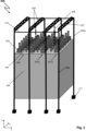
- FIG 1 shows a schematic and simplified perspective view of a reformer furnace 100 with a steel construction according to the state of the art.
- the radiation chamber of the reformer furnace 100 is shown, which has the actual steel construction, a fireproof lining and several rows of reformer tubes and burner rows.
- the steel construction serves to attach the burners, reformer tubes, as well as supply and discharge lines to/from the burners/reformer tubes. Details with regard to the fastening means are not shown for reasons of clarity.
- the reformer furnace 100 shown has four burner rows 101a, 101b and three reformer tube rows 102.
- Each of the burner rows 101a, 101b has six burners 103 arranged in a row.
- Each of the reformer tube rows 102 has eight reformer tubes 104 arranged in a row.
- the burner rows arranged on the left and right edges of the illustration are the wall-mounted burner rows 101a, which only fire one adjacent and parallel reformer tube row 102.
- the burner rows arranged between the wall-mounted burner rows 101a are the non-wall-mounted burner rows 101b, which each fire two adjacent and parallel reformer tube rows 102.
- the reformer tube rows 102 and the burner rows 101a, 101b each extend in the z direction of the illustration.
- the burners 103 each produce downward-directed flames, i.e. the flame extends essentially in the y-direction of the drawing and thereby heats the vertically arranged reformer tubes 104, which also extend in the y-direction.
- the burners 103 extend into the firing chamber of the radiation chamber of the reformer furnace, which is defined by the refractory lining 105 as a boundary to the outside.
- the vertically extending reformer tubes 103 penetrate the ceiling and the floor of the refractory lining 105 in such a way that the main length of a reformer tube 104 is defined by the adjacently arranged Burner can be heated.
- the supply lines for supplying the burners with fuel gas and oxidizing agent and the reformer tubes with reactant gas are not shown for reasons of clarity. The same applies to the exhaust gas channels and drains for removing the burner exhaust gases and the drains for removing the product gases.
- the steel construction of the reformer furnace shown has a total of three main support units.
- Each of the main support units has two vertical supports 106a and 106b and a horizontal main support 107.
- the supports 106a, 106b each have a base 111.
- the horizontally running main support 107 connects the two vertically running supports by means of a force-fitting or material-fitting connection, for example by means of a screwed connection or a welded connection.
- two are arranged on the end faces (front and back, each defined by the xy plane) of the reformer furnace, and one of the main support units is arranged between these main support units arranged on the end faces.
- auxiliary supports 108 are arranged that run vertically and are connected to the main supports.
- the auxiliary supports 108 serve to provide additional stabilization of the steel structure.
- the auxiliary supports 108 penetrate the ceiling of the refractory lining 105 and are thus arranged partially within the firing chamber of the reformer furnace 100. In the example of the reformer furnace 100, three auxiliary supports 108 are provided for each main support unit.
- the number of auxiliary supports 108 depends fundamentally on the width of the reformer furnace, i.e. on the number of rows of reformer tubes and rows of burners.
- the steel structure Above the main beams 107, the steel structure has a lattice structure 109 that is force-fitted to the main beam 107 for additional static stabilization and has diagonally and vertically arranged and interconnected struts.
- the horizontally running main supports 107 of the main support units are arranged orthogonally to the burner rows 101a, 101b and the reformer tube rows 102.
- the main supports 107 run in the x-direction of the illustration, while the burner rows 101a, 101b and reformer tube rows 102 run in the z-direction of the illustration.
- the third main support unit arranged between the main support units arranged at the front is required in order to meet the static requirements of the reformer tube row length and burner row length shown.
- the number of main support units of a conventional reformer furnace increases with the length of a reformer tube row 102 and the length of a burner row 101a, 101b.
- the third main support unit takes up a certain amount of space, for example due to the vertically running auxiliary supports, which means that the distance between the third and fourth burners of a burner row 101a, 101b has to be increased in comparison to all other burner distances.
- This design restriction means that the reformer tubes 104 in the area of the central main support unit have higher operating temperatures, which leads to a reduced service life and/or results in a higher safety margin in the design of the reformer tubes.
- the higher temperatures of the fourth and fifth reformer tubes of a reformer tube row 102 in this case are caused by the fact that the The visibility factor of these reformer tubes to the burner flames is greater than the visibility factor of the other tubes.
- the centrally arranged main support unit divides the reformer furnace into two so-called "bays", with each bay having three rows of reformer tubes, each with four reformer tubes, and four rows of burners, each with three burners. Such a formation of bays is fundamentally undesirable.
- FIG. 2 shows a schematic and simplified perspective view of a reformer furnace 200 with a steel construction according to the invention.
- the radiation chamber of the reformer furnace 200 is shown, which has the actual steel construction, a refractory lining and several rows of reformer tubes and burner rows.
- the steel construction serves to attach the burners, reformer tubes, and supply and discharge lines to/from the burners/reformer tubes. Details with regard to the fastening means are not shown for reasons of clarity.
- the reformer oven 200 shown has, analogous to the reformer oven of the Figure 1 four burner rows 201a, 201b and three reformer tube rows 202.
- Each of the burner rows 201a, 201b has six burners 203 arranged in a row.
- Each of the reformer tube rows 202 has eight reformer tubes 204 arranged in a row.
- the burner rows arranged on the left and right edges of the illustration are the wall-mounted burner rows 201a, which only fire one adjacent and parallel reformer tube row 202.
- the burner rows arranged between the wall-mounted burner rows 201a are the non-wall-mounted burner rows 201b, which each fire two adjacent and parallel reformer tube rows 202.
- the reformer tube rows 202 and the burner rows 201a, 201b each extend in the z direction of the illustration.
- the burners 103 each produce downward-directed flames, i.e. the flame extends essentially in the y-direction of the drawing and thereby heats the vertically arranged reformer tubes 204.
- the burners 203 extend into the firing chamber of the radiation chamber of the reformer furnace 200, which is defined by the refractory lining 205 as a boundary to the outside.
- the vertically running reformer tubes 203 penetrate the ceiling and the floor of the refractory lining 205 in such a way that the main length of a reformer tube 204 can be heated by the adjacently arranged burners.
- the supply lines for supplying the burners with fuel gas and oxidizing agent and the reformer tubes with reactant gas are not shown for reasons of clarity. The same applies to the exhaust gas channels and discharge lines for removing the burner exhaust gases and the discharge lines for removing the product gases.
- the steel construction of the reformer furnace shown has a total of four main support units.
- Each of the four main support units has two vertical supports 206a and 206b and a horizontal main support 207.
- the supports 206a, 206b each have a base 211.
- the horizontally running main support 207 connects the two vertically running supports by means of a force-fitting or material-fitting connection, for example by means of a screwed connection or a welded connection.
- Two of the main support units are arranged flush with the wall on the side surfaces (each defined by the yz plane) of the reformer furnace, and two of the main support units are arranged between the aforementioned main support units. All vertical supports 206a, 206b of the main support units are arranged flush with the wall.
- the supports 206a, 206b of the two main support units arranged between the main support units arranged on the side surfaces run along the surfaces of the front sides (defined by the xy plane) of the reformer furnace 200.
- the supports 206a, 206b of the main support units arranged on the side surfaces run in the region of the boundary between the walls of the front sides (xy plane) and the walls of the side surfaces (yz plane) of the reformer furnace 200.
- the walls of the reformer furnace enclose the radiation chamber together with the steel structure, the refractory lining 205 and the burners 203 and reformer tubes 204.
- the walls of the reformer furnace 200 are not shown for reasons of clarity.
- auxiliary supports 208 are arranged, connected to the main supports.
- the auxiliary supports 208 serve to provide additional stabilization of the steel structure.
- the auxiliary supports 208 penetrate the ceiling of the refractory lining 205 and are thus partially arranged within the firing chamber of the reformer furnace 200.
- one auxiliary support 208 is provided for each main support 207 that is not attached to the wall.
- the number of auxiliary supports 208 basically depends on the length of the reformer furnace, i.e. on the number of reformer tubes 204 and burners 203 per reformer tube or burner row.
- the steel structure has a lattice structure 209 for additional static stabilization, which is connected to the main beam 207 in a force-locking manner and has diagonally and vertically arranged and interconnected struts.
- the supports of the main beam units are connected to one another by horizontally running cross beams 210.
- the cross beams serve to stabilize the reformer furnace, but do not bear the main load of the burners 203 and reformer tubes 204 or any other existing supply and discharge lines.
- the horizontally running main supports 207 of the main support units are arranged parallel to the burner rows 201a, 201b and the reformer tube rows 202.
- the main supports 207 run in the z-direction of the illustration, which also applies to the burner rows 201a, 201b and reformer tube rows 202, which also extend in the z-direction.
- the burners 203 and reformer tubes 204 can be arranged evenly spaced apart in each row. The number of main support units required increases with the number of reformer tube rows and burner rows.
- one main support unit is required per burner row and one main support unit more than there are reformer tube rows.
- there is no upper limit to the number of reformer tubes and burners per row since any number of auxiliary supports 208 can be arranged between the supports 206a and 207a. which run between the reformer tube rows 202 and burner rows 201a, 201b and thus do not disturb the row symmetry.
- the steel construction according to the invention enables the construction of a reformer furnace which does not require any "bays" due to the uniform spacing of the reformer tubes.
- Figure 3a shows a section of a reformer tube row of the reformer furnace 100 with six reformer tubes 301a and associated heat profile 302a.
- the main support 303a of a main support unit runs orthogonally to the reformer tube row and therefore requires, as explained above, a larger distance between those reformer tubes 301a that run in the area of the main support 303a. This results in an unfavorable heat profile in this area compared to the rest of the reformer tube row. This is caused in particular by the greater visibility factor of the reformer tubes arranged in the area of the main support 303a to the neighboring burner flames.
- Figure 3b shows the analogous case for a reformer furnace 200 according to the invention with reformer tubes 301b and associated heat profile 302b.
- the uniform spacing of the reformer tubes 301b also evens out the heat profile 302b, whereby the maximum operating temperature of a reformer tube 301b can be reduced.
- the reformer furnace 200 according to the invention advantageously has no "bays".
Landscapes
- Chemical & Material Sciences (AREA)
- Chemical Kinetics & Catalysis (AREA)
- Organic Chemistry (AREA)
- Hydrogen, Water And Hydrids (AREA)
- Health & Medical Sciences (AREA)
- General Health & Medical Sciences (AREA)
- Engineering & Computer Science (AREA)
- Combustion & Propulsion (AREA)
- Inorganic Chemistry (AREA)
Claims (15)
- Four de reformage (200) pour le reformage catalytique d'une charge d'alimentation carbonée avec de la vapeur d'eau, présentantun espace de rayonnement défini par une pluralité de parois, délimité par rapport à l'environnement extérieur, l'espace de rayonnement comprenant une construction en acier réalisée sous forme d'ossature pour la fixation de conduites tubulaires d'amenée et d'évacuation, de brûleurs (203) et de tubes de reformage (204) agencés verticalement,les brûleurs (203) étant agencés pour générer des flammes dirigées vers le bas ou vers le haut pour chauffer les tubes de reformage (204), et les brûleurs (203) et les tubes de reformage (204) étant agencés à l'intérieur de l'espace de rayonnement en rangées sous forme de rangées de brûleurs (201a, 201b) et de rangées de tubes de reformage (202), les rangées de brûleurs (201a, 201b) et les rangées de tubes de reformage (202) étant agencées en alternance et parallèlement les unes aux autres, etla structure en acier présentant une pluralité d'unités de support principales, chaque unité de support principale présentant deux soutiens (206a, 206b) s'étendant verticalement, agencés au niveau de la paroi, ainsi qu'un support principal (207) s'étendant horizontalement et relié par l'intermédiaire des soutiens, qui s'étend sur toute la longueur de l'espace de rayonnement, etles supports principaux (207) étant configurés pour fixer les conduites tubulaires d'amenée et d'évacuation, les brûleurs (203) et les tubes de reformage (204), etla construction en acier présentant une pluralité de supports transversaux (210) s'étendant horizontalement, qui relient entre eux les soutiens des unités de support principales,caractérisé en ce queles supports principaux (207) des unités de support principales sont agencés parallèlement aux rangées de tubes de reformeur (202) et aux rangées de brûleurs (201a, 201b) et les supports transversaux (210) sont agencés au moins partiellement orthogonalement aux rangées de tubes de reformeur (202) et aux rangées de brûleurs (201a, 201b).
- Four de reformage selon la revendication 1, caractérisé en ce que le nombre d'unités de support principales est une fonction du nombre de rangées de tubes de reformage (202) et/ou une fonction du nombre de rangées de brûleurs (201a, 201b).
- Four de reformage selon la revendication 1 ou 2, caractérisé en ce que l'espace de rayonnement présente un nombre h d'unités de support principales, et un nombre r de rangées de tubes de reformage (202), la relation h = r + 1 s'appliquant entre h et r.
- Four de reformage selon l'une quelconque des revendications précédentes, caractérisé en ce que l'espace de rayonnement présente un nombre h d'unités de support principales, et un nombre b de rangées de brûleurs (201a, 201b), la relation h = b s'appliquant entre h et b.
- Four de reformage selon l'une quelconque des revendications précédentes, caractérisé en ce que le nombre d'unités de support principales n'est pas fonction de la longueur d'une rangée de tubes de reformage (202) et/ou le nombre d'unités de support principales n'est pas fonction de la longueur d'une rangée de brûleurs (201a, 201b) .
- Four de reformage selon l'une quelconque des revendications précédentes, caractérisé en ce qu'entre deux unités de support principales voisines- une seule rangée de brûleurs (201a, 201b) est agencée ou- une rangée de brûleurs (201a, 201b) et une rangée de tubes de reformage (202) voisine de la rangée de brûleurs sont agencées.
- Four de reformage selon la revendication 6, caractérisé en ce que la rangée de brûleurs unique est une rangée de brûleurs au niveau de la paroi (201a).
- Four de reformage selon l'une quelconque des revendications précédentes, caractérisé en ce que deux de la pluralité d'unités de support principales sont agencées sur deux parois opposées de l'espace de rayonnement, respectivement au niveau de la paroi, les supports principaux des unités de support principales positionnées au niveau de la paroi s'étendant parallèlement à la paroi respective.
- Four de reformage selon la revendication 8, caractérisé en ce que les unités de support principales agencées au niveau de la paroi disposent de plus de deux soutiens (206a, 206b) agencés au niveau de la paroi, s'étendant verticalement.
- Four de reformage selon l'une quelconque des revendications précédentes, caractérisé en ce que toutes les distances entre deux tubes de reformage (204) voisins à l'intérieur d'une rangée de tubes de reformage (202) et/ou toutes les distances entre deux brûleurs (203) voisins à l'intérieur d'une rangée de brûleurs (201a, 201b) sont égales à l'intérieur de l'ensemble de l'espace de rayonnement du four de reformage.
- Four de reformage selon l'une quelconque des revendications précédentes, caractérisé en ce que toutes les distances entre deux tubes de reformage (204) voisins, mesurées par l'horizontale s'étendant entre deux axes de tubes de reformage de tubes de reformage (204) voisins, sont inférieures ou égales à 500 mm, de préférence se situent dans une plage de 250 à 450 mm, de manière davantage préférée se situent dans une plage de 280 à 320 mm.
- Four de reformage selon l'une quelconque des revendications précédentes, caractérisé en ce que la température du gaz produit évacué par les conduites tubulaires d'évacuation est en moyenne jusqu'à 950 °C, de préférence dans une plage de 900 à 950 °C, de manière davantage préférée dans une plage de 925 à 950 °C.
- Four de reformage selon l'une quelconque des revendications précédentes, caractérisé en ce que la structure en acier sert d'ossature pour un revêtement réfractaire de l'espace de rayonnement, l'espace à l'intérieur du revêtement réfractaire définissant un espace d'allumage pour l'allumage des tubes de reformage (204) .
- Four de reformage selon l'une quelconque des revendications précédentes, caractérisé en ce que chaque unité de support principale présente une construction en treillis (209) agencée au-dessus de l'unité de support principale et reliée par adhérence au support principal.
- Utilisation d'un four de reformage (200) selon l'une quelconque des revendications précédentes pour le reformage à la vapeur d'une charge d'alimentation carbonée, notamment de gaz naturel.
Priority Applications (8)
| Application Number | Priority Date | Filing Date | Title |
|---|---|---|---|
| ES19020710T ES2998583T3 (en) | 2019-12-19 | 2019-12-19 | Reformer furnace and its use for steam reforming |
| EP19020710.0A EP3838397B1 (fr) | 2019-12-19 | 2019-12-19 | Four reformeur et son utilisation pour le reformage à la vapeur |
| PT190207100T PT3838397T (pt) | 2019-12-19 | 2019-12-19 | Forno reformador e respetiva utilização para reforma a vapor |
| KR1020227024249A KR20220110577A (ko) | 2019-12-19 | 2020-11-30 | 개질로 |
| US17/786,357 US11813603B2 (en) | 2019-12-19 | 2020-11-30 | Reformer furnace |
| CA3162351A CA3162351A1 (fr) | 2019-12-19 | 2020-11-30 | Four de reformage |
| PCT/EP2020/025549 WO2021121651A1 (fr) | 2019-12-19 | 2020-11-30 | Four de reformage |
| CN202080079911.1A CN114728262B (zh) | 2019-12-19 | 2020-11-30 | 重整炉 |
Applications Claiming Priority (1)
| Application Number | Priority Date | Filing Date | Title |
|---|---|---|---|
| EP19020710.0A EP3838397B1 (fr) | 2019-12-19 | 2019-12-19 | Four reformeur et son utilisation pour le reformage à la vapeur |
Publications (2)
| Publication Number | Publication Date |
|---|---|
| EP3838397A1 EP3838397A1 (fr) | 2021-06-23 |
| EP3838397B1 true EP3838397B1 (fr) | 2024-09-04 |
Family
ID=69410894
Family Applications (1)
| Application Number | Title | Priority Date | Filing Date |
|---|---|---|---|
| EP19020710.0A Active EP3838397B1 (fr) | 2019-12-19 | 2019-12-19 | Four reformeur et son utilisation pour le reformage à la vapeur |
Country Status (8)
| Country | Link |
|---|---|
| US (1) | US11813603B2 (fr) |
| EP (1) | EP3838397B1 (fr) |
| KR (1) | KR20220110577A (fr) |
| CN (1) | CN114728262B (fr) |
| CA (1) | CA3162351A1 (fr) |
| ES (1) | ES2998583T3 (fr) |
| PT (1) | PT3838397T (fr) |
| WO (1) | WO2021121651A1 (fr) |
Family Cites Families (11)
| Publication number | Priority date | Publication date | Assignee | Title |
|---|---|---|---|---|
| NL245636A (fr) * | 1958-12-05 | |||
| JP4590202B2 (ja) * | 2004-04-02 | 2010-12-01 | 日産自動車株式会社 | 燃料改質反応器 |
| KR101266673B1 (ko) * | 2007-11-01 | 2013-05-28 | 에스케이이노베이션 주식회사 | 수증기 개질방식에 의한 수소발생장치 |
| DE102011120938A1 (de) | 2011-12-14 | 2013-06-20 | Thyssenkrupp Uhde Gmbh | Transportabler Reformer |
| JP2015517175A (ja) * | 2012-03-08 | 2015-06-18 | ヘルビオ ソシエテ アノニム ハイドロジェン アンド エナジー プロダクション システムズ | 燃料電池のための触媒を支持する置換可能な構造化支持部を含む触媒加熱式燃料処理装置 |
| PL2708812T3 (pl) * | 2012-09-13 | 2017-12-29 | L'Air Liquide, Société Anonyme pour l'Etude et l'Exploitation des Procédés Georges Claude | Proces i urządzenie do reakcji endotermicznych |
| PL3182003T3 (pl) * | 2015-12-15 | 2021-10-25 | L'air Liquide, Societe Anonyme Pour L'etude Et L'exploitation Des Procedes Georges Claude | Urządzenie do procesu endotermicznego z ulepszonym układem palników |
| DK3279561T3 (da) * | 2016-08-02 | 2019-07-29 | Air Liquide | Indretning til endotermisk proces med forbedret røranordning |
| US20180178188A1 (en) * | 2016-12-22 | 2018-06-28 | Extiel Holdings, Llc | Sectionalized box style steam methane reformer |
| US10871749B2 (en) | 2017-11-08 | 2020-12-22 | Ford Global Technologies, Llc | System and method for control module alarm wake |
| CN109747517B (zh) * | 2017-11-08 | 2021-10-01 | 上海宝冶集团有限公司 | 蒸汽转化炉辐射段支撑框架模块化运输的方法 |
-
2019
- 2019-12-19 ES ES19020710T patent/ES2998583T3/es active Active
- 2019-12-19 PT PT190207100T patent/PT3838397T/pt unknown
- 2019-12-19 EP EP19020710.0A patent/EP3838397B1/fr active Active
-
2020
- 2020-11-30 CN CN202080079911.1A patent/CN114728262B/zh active Active
- 2020-11-30 WO PCT/EP2020/025549 patent/WO2021121651A1/fr not_active Ceased
- 2020-11-30 CA CA3162351A patent/CA3162351A1/fr active Pending
- 2020-11-30 US US17/786,357 patent/US11813603B2/en active Active
- 2020-11-30 KR KR1020227024249A patent/KR20220110577A/ko active Pending
Also Published As
| Publication number | Publication date |
|---|---|
| US20230023054A1 (en) | 2023-01-26 |
| CA3162351A1 (fr) | 2021-06-24 |
| ES2998583T3 (en) | 2025-02-20 |
| US11813603B2 (en) | 2023-11-14 |
| WO2021121651A1 (fr) | 2021-06-24 |
| PT3838397T (pt) | 2024-11-25 |
| CN114728262A (zh) | 2022-07-08 |
| KR20220110577A (ko) | 2022-08-08 |
| CN114728262B (zh) | 2025-04-01 |
| EP3838397A1 (fr) | 2021-06-23 |
Similar Documents
| Publication | Publication Date | Title |
|---|---|---|
| EP0433222B1 (fr) | Réacteur avec un corps de catalyseur pour effectuer une réaction hétérogène | |
| DE212012000120U1 (de) | Wärmetauschreaktor | |
| DE69502611T2 (de) | Reaktor für exothermische, heterogene katalytische synthesereaktionen | |
| DE102010001065A1 (de) | Leitscheibenanordnung für einen Wärmetauscher, Wärmetauscher, Verfahren zum Herstellen eines Wärmetauschers sowie Aus- oder Nachrüstkit für einen Wärmetauscher | |
| DE1442740A1 (de) | Ofen zum Erhitzen fliessfaehiger Reaktionsteilnehmer in Gegenwart eines Katalysators | |
| DE3425732C2 (de) | Ofen zum Brennen keramischer Materialien | |
| DE2147802A1 (fr) | ||
| EP3838397B1 (fr) | Four reformeur et son utilisation pour le reformage à la vapeur | |
| EP0019652B1 (fr) | Grille pour un chauffage à lit fluidisé | |
| EP0427828B1 (fr) | Chambre de chauffage dans des fours a coke et procede de chauffage | |
| EP3068529A1 (fr) | Procédé et dispositif de reformage à la vapeur et de clivage à la vapeur d'hydrocarbures | |
| EP1027922A2 (fr) | Réacteur pour de réactions catalytiques exothermiques de substances en phase gazeuse | |
| EP3153465A1 (fr) | Reformateur destine a la fabrication d'un gaz de synthese | |
| EP0275513A1 (fr) | Système de cokéfaction et bloc de réacteurs | |
| DE2413752C3 (de) | Vertikalrohrofen zur Herstellung von Äthylen durch Krackung | |
| EP3821973B1 (fr) | Four de reformage permettant de mettre en uvre un processus endothermique | |
| EP0961084B1 (fr) | Chauffage à plaques rayonnantes de plafond | |
| DE102011100211A1 (de) | System aus Deckenstrahlplatten und Gebäude hiermit | |
| DE602004007029T2 (de) | Katalytischer reaktor unter pseudo-isothermischen bedingungen | |
| DE1007300B (de) | Unteres Ofenverschlussteil fuer OEfen, insbesondere Reaktionsoefen | |
| DE69401203T2 (de) | Wirbelbettreaktorsystem und methode zu dessen herstellung | |
| WO2016066297A1 (fr) | Reformeur pourvu de brûleurs poreux ou surfaciques | |
| DE2754034A1 (de) | Durchlauf-retortenofen | |
| DE202015105493U1 (de) | Reformer zur Erzeugung von Synthesegas | |
| DE3328431A1 (de) | Heizer fuer eine isostatische heisspressvorrichtung |
Legal Events
| Date | Code | Title | Description |
|---|---|---|---|
| PUAI | Public reference made under article 153(3) epc to a published international application that has entered the european phase |
Free format text: ORIGINAL CODE: 0009012 |
|
| STAA | Information on the status of an ep patent application or granted ep patent |
Free format text: STATUS: THE APPLICATION HAS BEEN PUBLISHED |
|
| AK | Designated contracting states |
Kind code of ref document: A1 Designated state(s): AL AT BE BG CH CY CZ DE DK EE ES FI FR GB GR HR HU IE IS IT LI LT LU LV MC MK MT NL NO PL PT RO RS SE SI SK SM TR |
|
| STAA | Information on the status of an ep patent application or granted ep patent |
Free format text: STATUS: REQUEST FOR EXAMINATION WAS MADE |
|
| 17P | Request for examination filed |
Effective date: 20211223 |
|
| RBV | Designated contracting states (corrected) |
Designated state(s): AL AT BE BG CH CY CZ DE DK EE ES FI FR GB GR HR HU IE IS IT LI LT LU LV MC MK MT NL NO PL PT RO RS SE SI SK SM TR |
|
| STAA | Information on the status of an ep patent application or granted ep patent |
Free format text: STATUS: EXAMINATION IS IN PROGRESS |
|
| 17Q | First examination report despatched |
Effective date: 20231124 |
|
| GRAP | Despatch of communication of intention to grant a patent |
Free format text: ORIGINAL CODE: EPIDOSNIGR1 |
|
| STAA | Information on the status of an ep patent application or granted ep patent |
Free format text: STATUS: GRANT OF PATENT IS INTENDED |
|
| INTG | Intention to grant announced |
Effective date: 20240410 |
|
| GRAS | Grant fee paid |
Free format text: ORIGINAL CODE: EPIDOSNIGR3 |
|
| GRAA | (expected) grant |
Free format text: ORIGINAL CODE: 0009210 |
|
| STAA | Information on the status of an ep patent application or granted ep patent |
Free format text: STATUS: THE PATENT HAS BEEN GRANTED |
|
| AK | Designated contracting states |
Kind code of ref document: B1 Designated state(s): AL AT BE BG CH CY CZ DE DK EE ES FI FR GB GR HR HU IE IS IT LI LT LU LV MC MK MT NL NO PL PT RO RS SE SI SK SM TR |
|
| REG | Reference to a national code |
Ref country code: GB Ref legal event code: FG4D Free format text: NOT ENGLISH |
|
| REG | Reference to a national code |
Ref country code: CH Ref legal event code: EP |
|
| REG | Reference to a national code |
Ref country code: IE Ref legal event code: FG4D Free format text: LANGUAGE OF EP DOCUMENT: GERMAN |
|
| REG | Reference to a national code |
Ref country code: DE Ref legal event code: R096 Ref document number: 502019012020 Country of ref document: DE |
|
| REG | Reference to a national code |
Ref country code: PT Ref legal event code: SC4A Ref document number: 3838397 Country of ref document: PT Date of ref document: 20241125 Kind code of ref document: T Free format text: AVAILABILITY OF NATIONAL TRANSLATION Effective date: 20241120 |
|
| REG | Reference to a national code |
Ref country code: NL Ref legal event code: FP |
|
| PGFP | Annual fee paid to national office [announced via postgrant information from national office to epo] |
Ref country code: PT Payment date: 20241205 Year of fee payment: 6 |
|
| REG | Reference to a national code |
Ref country code: LT Ref legal event code: MG9D |
|
| REG | Reference to a national code |
Ref country code: SE Ref legal event code: TRGR |
|
| PGFP | Annual fee paid to national office [announced via postgrant information from national office to epo] |
Ref country code: DE Payment date: 20241210 Year of fee payment: 6 |
|
| PG25 | Lapsed in a contracting state [announced via postgrant information from national office to epo] |
Ref country code: NO Free format text: LAPSE BECAUSE OF FAILURE TO SUBMIT A TRANSLATION OF THE DESCRIPTION OR TO PAY THE FEE WITHIN THE PRESCRIBED TIME-LIMIT Effective date: 20241204 |
|
| PG25 | Lapsed in a contracting state [announced via postgrant information from national office to epo] |
Ref country code: GR Free format text: LAPSE BECAUSE OF FAILURE TO SUBMIT A TRANSLATION OF THE DESCRIPTION OR TO PAY THE FEE WITHIN THE PRESCRIBED TIME-LIMIT Effective date: 20241205 Ref country code: FI Free format text: LAPSE BECAUSE OF FAILURE TO SUBMIT A TRANSLATION OF THE DESCRIPTION OR TO PAY THE FEE WITHIN THE PRESCRIBED TIME-LIMIT Effective date: 20240904 Ref country code: PL Free format text: LAPSE BECAUSE OF FAILURE TO SUBMIT A TRANSLATION OF THE DESCRIPTION OR TO PAY THE FEE WITHIN THE PRESCRIBED TIME-LIMIT Effective date: 20240904 |
|
| PGFP | Annual fee paid to national office [announced via postgrant information from national office to epo] |
Ref country code: NL Payment date: 20241219 Year of fee payment: 6 Ref country code: BE Payment date: 20241219 Year of fee payment: 6 |
|
| PGFP | Annual fee paid to national office [announced via postgrant information from national office to epo] |
Ref country code: GB Payment date: 20241227 Year of fee payment: 6 |
|
| PG25 | Lapsed in a contracting state [announced via postgrant information from national office to epo] |
Ref country code: BG Free format text: LAPSE BECAUSE OF FAILURE TO SUBMIT A TRANSLATION OF THE DESCRIPTION OR TO PAY THE FEE WITHIN THE PRESCRIBED TIME-LIMIT Effective date: 20240904 |
|
| PGFP | Annual fee paid to national office [announced via postgrant information from national office to epo] |
Ref country code: FR Payment date: 20241224 Year of fee payment: 6 |
|
| PG25 | Lapsed in a contracting state [announced via postgrant information from national office to epo] |
Ref country code: LV Free format text: LAPSE BECAUSE OF FAILURE TO SUBMIT A TRANSLATION OF THE DESCRIPTION OR TO PAY THE FEE WITHIN THE PRESCRIBED TIME-LIMIT Effective date: 20240904 |
|
| PG25 | Lapsed in a contracting state [announced via postgrant information from national office to epo] |
Ref country code: HR Free format text: LAPSE BECAUSE OF FAILURE TO SUBMIT A TRANSLATION OF THE DESCRIPTION OR TO PAY THE FEE WITHIN THE PRESCRIBED TIME-LIMIT Effective date: 20240904 |
|
| PG25 | Lapsed in a contracting state [announced via postgrant information from national office to epo] |
Ref country code: RS Free format text: LAPSE BECAUSE OF FAILURE TO SUBMIT A TRANSLATION OF THE DESCRIPTION OR TO PAY THE FEE WITHIN THE PRESCRIBED TIME-LIMIT Effective date: 20241204 |
|
| PGFP | Annual fee paid to national office [announced via postgrant information from national office to epo] |
Ref country code: SE Payment date: 20241219 Year of fee payment: 6 |
|
| PG25 | Lapsed in a contracting state [announced via postgrant information from national office to epo] |
Ref country code: RS Free format text: LAPSE BECAUSE OF FAILURE TO SUBMIT A TRANSLATION OF THE DESCRIPTION OR TO PAY THE FEE WITHIN THE PRESCRIBED TIME-LIMIT Effective date: 20241204 Ref country code: PL Free format text: LAPSE BECAUSE OF FAILURE TO SUBMIT A TRANSLATION OF THE DESCRIPTION OR TO PAY THE FEE WITHIN THE PRESCRIBED TIME-LIMIT Effective date: 20240904 Ref country code: NO Free format text: LAPSE BECAUSE OF FAILURE TO SUBMIT A TRANSLATION OF THE DESCRIPTION OR TO PAY THE FEE WITHIN THE PRESCRIBED TIME-LIMIT Effective date: 20241204 Ref country code: LV Free format text: LAPSE BECAUSE OF FAILURE TO SUBMIT A TRANSLATION OF THE DESCRIPTION OR TO PAY THE FEE WITHIN THE PRESCRIBED TIME-LIMIT Effective date: 20240904 Ref country code: HR Free format text: LAPSE BECAUSE OF FAILURE TO SUBMIT A TRANSLATION OF THE DESCRIPTION OR TO PAY THE FEE WITHIN THE PRESCRIBED TIME-LIMIT Effective date: 20240904 Ref country code: GR Free format text: LAPSE BECAUSE OF FAILURE TO SUBMIT A TRANSLATION OF THE DESCRIPTION OR TO PAY THE FEE WITHIN THE PRESCRIBED TIME-LIMIT Effective date: 20241205 Ref country code: FI Free format text: LAPSE BECAUSE OF FAILURE TO SUBMIT A TRANSLATION OF THE DESCRIPTION OR TO PAY THE FEE WITHIN THE PRESCRIBED TIME-LIMIT Effective date: 20240904 Ref country code: BG Free format text: LAPSE BECAUSE OF FAILURE TO SUBMIT A TRANSLATION OF THE DESCRIPTION OR TO PAY THE FEE WITHIN THE PRESCRIBED TIME-LIMIT Effective date: 20240904 |
|
| REG | Reference to a national code |
Ref country code: ES Ref legal event code: FG2A Ref document number: 2998583 Country of ref document: ES Kind code of ref document: T3 Effective date: 20250220 |
|
| PG25 | Lapsed in a contracting state [announced via postgrant information from national office to epo] |
Ref country code: IS Free format text: LAPSE BECAUSE OF FAILURE TO SUBMIT A TRANSLATION OF THE DESCRIPTION OR TO PAY THE FEE WITHIN THE PRESCRIBED TIME-LIMIT Effective date: 20250104 |
|
| PG25 | Lapsed in a contracting state [announced via postgrant information from national office to epo] |
Ref country code: SM Free format text: LAPSE BECAUSE OF FAILURE TO SUBMIT A TRANSLATION OF THE DESCRIPTION OR TO PAY THE FEE WITHIN THE PRESCRIBED TIME-LIMIT Effective date: 20240904 Ref country code: RO Free format text: LAPSE BECAUSE OF FAILURE TO SUBMIT A TRANSLATION OF THE DESCRIPTION OR TO PAY THE FEE WITHIN THE PRESCRIBED TIME-LIMIT Effective date: 20240904 |
|
| PGFP | Annual fee paid to national office [announced via postgrant information from national office to epo] |
Ref country code: ES Payment date: 20250131 Year of fee payment: 6 |
|
| PG25 | Lapsed in a contracting state [announced via postgrant information from national office to epo] |
Ref country code: EE Free format text: LAPSE BECAUSE OF FAILURE TO SUBMIT A TRANSLATION OF THE DESCRIPTION OR TO PAY THE FEE WITHIN THE PRESCRIBED TIME-LIMIT Effective date: 20240904 |
|
| PG25 | Lapsed in a contracting state [announced via postgrant information from national office to epo] |
Ref country code: CZ Free format text: LAPSE BECAUSE OF FAILURE TO SUBMIT A TRANSLATION OF THE DESCRIPTION OR TO PAY THE FEE WITHIN THE PRESCRIBED TIME-LIMIT Effective date: 20240904 |
|
| PG25 | Lapsed in a contracting state [announced via postgrant information from national office to epo] |
Ref country code: SK Free format text: LAPSE BECAUSE OF FAILURE TO SUBMIT A TRANSLATION OF THE DESCRIPTION OR TO PAY THE FEE WITHIN THE PRESCRIBED TIME-LIMIT Effective date: 20240904 |
|
| PGFP | Annual fee paid to national office [announced via postgrant information from national office to epo] |
Ref country code: IT Payment date: 20241230 Year of fee payment: 6 |
|
| REG | Reference to a national code |
Ref country code: DE Ref legal event code: R097 Ref document number: 502019012020 Country of ref document: DE |
|
| PG25 | Lapsed in a contracting state [announced via postgrant information from national office to epo] |
Ref country code: MC Free format text: LAPSE BECAUSE OF FAILURE TO SUBMIT A TRANSLATION OF THE DESCRIPTION OR TO PAY THE FEE WITHIN THE PRESCRIBED TIME-LIMIT Effective date: 20240904 |
|
| PG25 | Lapsed in a contracting state [announced via postgrant information from national office to epo] |
Ref country code: DK Free format text: LAPSE BECAUSE OF FAILURE TO SUBMIT A TRANSLATION OF THE DESCRIPTION OR TO PAY THE FEE WITHIN THE PRESCRIBED TIME-LIMIT Effective date: 20240904 |
|
| PLBE | No opposition filed within time limit |
Free format text: ORIGINAL CODE: 0009261 |
|
| STAA | Information on the status of an ep patent application or granted ep patent |
Free format text: STATUS: NO OPPOSITION FILED WITHIN TIME LIMIT |
|
| REG | Reference to a national code |
Ref country code: CH Ref legal event code: PL |
|
| 26N | No opposition filed |
Effective date: 20250605 |
|
| PG25 | Lapsed in a contracting state [announced via postgrant information from national office to epo] |
Ref country code: LU Free format text: LAPSE BECAUSE OF NON-PAYMENT OF DUE FEES Effective date: 20241219 |
|
| PG25 | Lapsed in a contracting state [announced via postgrant information from national office to epo] |
Ref country code: CH Free format text: LAPSE BECAUSE OF NON-PAYMENT OF DUE FEES Effective date: 20241231 |
|
| PG25 | Lapsed in a contracting state [announced via postgrant information from national office to epo] |
Ref country code: IE Free format text: LAPSE BECAUSE OF NON-PAYMENT OF DUE FEES Effective date: 20241219 |