EP3836765A1 - Electrical insulation module for high-voltage electrical equipment - Google Patents
Electrical insulation module for high-voltage electrical equipment Download PDFInfo
- Publication number
- EP3836765A1 EP3836765A1 EP20210388.3A EP20210388A EP3836765A1 EP 3836765 A1 EP3836765 A1 EP 3836765A1 EP 20210388 A EP20210388 A EP 20210388A EP 3836765 A1 EP3836765 A1 EP 3836765A1
- Authority
- EP
- European Patent Office
- Prior art keywords
- electrical
- peripheral wall
- electrical component
- housing
- wall
- Prior art date
- Legal status (The legal status is an assumption and is not a legal conclusion. Google has not performed a legal analysis and makes no representation as to the accuracy of the status listed.)
- Pending
Links
- 238000010292 electrical insulation Methods 0.000 title claims abstract description 29
- 230000002093 peripheral effect Effects 0.000 claims abstract description 74
- 125000006850 spacer group Chemical group 0.000 claims abstract description 32
- 239000011810 insulating material Substances 0.000 claims abstract description 6
- 238000002955 isolation Methods 0.000 claims abstract description 6
- 239000000463 material Substances 0.000 claims description 5
- 230000003071 parasitic effect Effects 0.000 description 3
- 238000005192 partition Methods 0.000 description 3
- 239000003990 capacitor Substances 0.000 description 2
- 239000004020 conductor Substances 0.000 description 2
- 230000017525 heat dissipation Effects 0.000 description 2
- 238000004519 manufacturing process Methods 0.000 description 2
- 229910052751 metal Inorganic materials 0.000 description 2
- 239000002184 metal Substances 0.000 description 2
- 229910000838 Al alloy Inorganic materials 0.000 description 1
- RYGMFSIKBFXOCR-UHFFFAOYSA-N Copper Chemical compound [Cu] RYGMFSIKBFXOCR-UHFFFAOYSA-N 0.000 description 1
- 229910000861 Mg alloy Inorganic materials 0.000 description 1
- OWXLRKWPEIAGAT-UHFFFAOYSA-N [Mg].[Cu] Chemical compound [Mg].[Cu] OWXLRKWPEIAGAT-UHFFFAOYSA-N 0.000 description 1
- 229910052782 aluminium Inorganic materials 0.000 description 1
- XAGFODPZIPBFFR-UHFFFAOYSA-N aluminium Chemical compound [Al] XAGFODPZIPBFFR-UHFFFAOYSA-N 0.000 description 1
- 229910010293 ceramic material Inorganic materials 0.000 description 1
- 229910052802 copper Inorganic materials 0.000 description 1
- 239000010949 copper Substances 0.000 description 1
- 239000013013 elastic material Substances 0.000 description 1
- 229910001092 metal group alloy Inorganic materials 0.000 description 1
- 239000007769 metal material Substances 0.000 description 1
- 238000000034 method Methods 0.000 description 1
- 229920001296 polysiloxane Polymers 0.000 description 1
- 239000007787 solid Substances 0.000 description 1
Images


Classifications
-
- H—ELECTRICITY
- H05—ELECTRIC TECHNIQUES NOT OTHERWISE PROVIDED FOR
- H05K—PRINTED CIRCUITS; CASINGS OR CONSTRUCTIONAL DETAILS OF ELECTRIC APPARATUS; MANUFACTURE OF ASSEMBLAGES OF ELECTRICAL COMPONENTS
- H05K7/00—Constructional details common to different types of electric apparatus
- H05K7/14—Mounting supporting structure in casing or on frame or rack
- H05K7/1422—Printed circuit boards receptacles, e.g. stacked structures, electronic circuit modules or box like frames
- H05K7/1427—Housings
- H05K7/1432—Housings specially adapted for power drive units or power converters
- H05K7/14339—Housings specially adapted for power drive units or power converters specially adapted for high voltage operation
-
- H—ELECTRICITY
- H05—ELECTRIC TECHNIQUES NOT OTHERWISE PROVIDED FOR
- H05K—PRINTED CIRCUITS; CASINGS OR CONSTRUCTIONAL DETAILS OF ELECTRIC APPARATUS; MANUFACTURE OF ASSEMBLAGES OF ELECTRICAL COMPONENTS
- H05K5/00—Casings, cabinets or drawers for electric apparatus
- H05K5/02—Details
- H05K5/0247—Electrical details of casings, e.g. terminals, passages for cables or wiring
-
- H—ELECTRICITY
- H02—GENERATION; CONVERSION OR DISTRIBUTION OF ELECTRIC POWER
- H02B—BOARDS, SUBSTATIONS OR SWITCHING ARRANGEMENTS FOR THE SUPPLY OR DISTRIBUTION OF ELECTRIC POWER
- H02B1/00—Frameworks, boards, panels, desks, casings; Details of substations or switching arrangements
- H02B1/26—Casings; Parts thereof or accessories therefor
-
- H—ELECTRICITY
- H05—ELECTRIC TECHNIQUES NOT OTHERWISE PROVIDED FOR
- H05K—PRINTED CIRCUITS; CASINGS OR CONSTRUCTIONAL DETAILS OF ELECTRIC APPARATUS; MANUFACTURE OF ASSEMBLAGES OF ELECTRICAL COMPONENTS
- H05K7/00—Constructional details common to different types of electric apparatus
- H05K7/02—Arrangements of circuit components or wiring on supporting structure
- H05K7/12—Resilient or clamping means for holding component to structure
-
- H—ELECTRICITY
- H02—GENERATION; CONVERSION OR DISTRIBUTION OF ELECTRIC POWER
- H02B—BOARDS, SUBSTATIONS OR SWITCHING ARRANGEMENTS FOR THE SUPPLY OR DISTRIBUTION OF ELECTRIC POWER
- H02B1/00—Frameworks, boards, panels, desks, casings; Details of substations or switching arrangements
- H02B1/14—Shutters or guards for preventing access to contacts
-
- H—ELECTRICITY
- H02—GENERATION; CONVERSION OR DISTRIBUTION OF ELECTRIC POWER
- H02M—APPARATUS FOR CONVERSION BETWEEN AC AND AC, BETWEEN AC AND DC, OR BETWEEN DC AND DC, AND FOR USE WITH MAINS OR SIMILAR POWER SUPPLY SYSTEMS; CONVERSION OF DC OR AC INPUT POWER INTO SURGE OUTPUT POWER; CONTROL OR REGULATION THEREOF
- H02M7/00—Conversion of ac power input into dc power output; Conversion of dc power input into ac power output
- H02M7/003—Constructional details, e.g. physical layout, assembly, wiring or busbar connections
-
- H—ELECTRICITY
- H05—ELECTRIC TECHNIQUES NOT OTHERWISE PROVIDED FOR
- H05K—PRINTED CIRCUITS; CASINGS OR CONSTRUCTIONAL DETAILS OF ELECTRIC APPARATUS; MANUFACTURE OF ASSEMBLAGES OF ELECTRICAL COMPONENTS
- H05K5/00—Casings, cabinets or drawers for electric apparatus
- H05K5/0004—Casings, cabinets or drawers for electric apparatus comprising several parts forming a closed casing
-
- H—ELECTRICITY
- H05—ELECTRIC TECHNIQUES NOT OTHERWISE PROVIDED FOR
- H05K—PRINTED CIRCUITS; CASINGS OR CONSTRUCTIONAL DETAILS OF ELECTRIC APPARATUS; MANUFACTURE OF ASSEMBLAGES OF ELECTRICAL COMPONENTS
- H05K5/00—Casings, cabinets or drawers for electric apparatus
- H05K5/02—Details
- H05K5/0213—Venting apertures; Constructional details thereof
-
- H—ELECTRICITY
- H05—ELECTRIC TECHNIQUES NOT OTHERWISE PROVIDED FOR
- H05K—PRINTED CIRCUITS; CASINGS OR CONSTRUCTIONAL DETAILS OF ELECTRIC APPARATUS; MANUFACTURE OF ASSEMBLAGES OF ELECTRICAL COMPONENTS
- H05K5/00—Casings, cabinets or drawers for electric apparatus
- H05K5/02—Details
- H05K5/0217—Mechanical details of casings
-
- H—ELECTRICITY
- H05—ELECTRIC TECHNIQUES NOT OTHERWISE PROVIDED FOR
- H05K—PRINTED CIRCUITS; CASINGS OR CONSTRUCTIONAL DETAILS OF ELECTRIC APPARATUS; MANUFACTURE OF ASSEMBLAGES OF ELECTRICAL COMPONENTS
- H05K7/00—Constructional details common to different types of electric apparatus
- H05K7/20—Modifications to facilitate cooling, ventilating, or heating
- H05K7/2089—Modifications to facilitate cooling, ventilating, or heating for power electronics, e.g. for inverters for controlling motor
- H05K7/209—Heat transfer by conduction from internal heat source to heat radiating structure
Abstract
L'invention concerne un module d'isolation électrique (5) configuré pour déterminer au moins une ligne de fuite (71, 72) entre un composant électrique (101) et un boîtier recevant ledit composant électrique (101). Le module d'isolation électrique (5), étant en matériau isolant électrique, comprend une entretoise (50) configurée pour définir l'au moins une ligne de fuite (71, 72) entre ledit composant électrique (101) et ledit boîtier. Ladite entretoise (50) comprend une paroi de fond (51) et une paroi périphérique (52), dans laquelle la paroi périphérique (52) suit une direction différente de celle de la paroi de fond (51), un angle interne (55) étant formé entre la paroi de fond (51) et la paroi périphérique (52) ; et l'au moins une ligne de fuite (71, 72) comprend au moins une dimension d'une surface correspondant à une portion de la paroi de fond (51) et/ou une dimension d'une surface d'une portion de la paroi périphérique (52).The invention relates to an electrical isolation module (5) configured to determine at least one leakage line (71, 72) between an electrical component (101) and a housing receiving said electrical component (101). The electrical insulation module (5), being made of an electrical insulating material, comprises a spacer (50) configured to define the at least one leakage line (71, 72) between said electrical component (101) and said housing. Said spacer (50) comprises a bottom wall (51) and a peripheral wall (52), in which the peripheral wall (52) follows a direction different from that of the bottom wall (51), an internal angle (55). being formed between the bottom wall (51) and the peripheral wall (52); and the at least one creepage line (71, 72) comprises at least one dimension of a surface corresponding to a portion of the bottom wall (51) and / or a dimension of a surface of a portion of the peripheral wall (52).
Description
La présente invention concerne, de façon générale, le domaine des équipements électriques.The present invention relates, in general, to the field of electrical equipment.
L'invention porte plus particulièrement sur des équipements électriques haute tension pour véhicules électriques ou hybrides.The invention relates more particularly to high voltage electrical equipment for electric or hybrid vehicles.
Un équipement électrique d'un véhicule électrique ou hybride, tel qu'un onduleur d'un véhicule électrique, comprend des composants électriques logés dans un boîtier de l'équipement électrique, comme illustré en
Pour améliorer la dissipation thermique et isoler le composant électrique 111 avec la plaque de base 115, l'équipement électrique comprend généralement un coussin thermique 66. Le coussin thermique 66 est placé entre la plaque de base 115 du boîtier 112 et le composant électrique 111. Le coussin thermique 66 est d'un matériau isolant et présente une conductivité thermique permettant une dissipation de la chaleur entre le composant électrique 111 et la plaque de base 115.To improve heat dissipation and insulate the
La différence de potentiel électrique entre le boîtier 112 et le composant électrique 111, notamment entre la paroi latérale 116 et le composant électrique 111, détermine une distance de sécurité électrique 131, qu'il faut respecter afin d'éviter la création d'un cheminement électrique parasitaire entre le composant électrique 111 et le boîtier 112 à travers l'air. Par exemple, dans l'équipement électrique 100, la distance minimale entre le composant électrique 111 et la paroi latérale 116 doit être d'une distance supérieure à cette distance de sécurité électrique 131, de façon à assurer que, durant l'utilisation de l'équipement électrique 100, il n'y ait pas de possibilité de rupture de l'isolation électrique à travers l'air.The difference in electrical potential between the box 112 and the
En outre la différence de potentiel électrique entre le boîtier 112 et le composant électrique 111, notamment entre la paroi de base 115 et le composant électrique 111, détermine une ligne de fuite 170. On détermine la ligne de fuite 170 comme le chemin de résistance le plus faible suivi par un courant électrique de surface parasitaire entre le composant électrique 111 et le boîtier 112, notamment entre le composant électrique 111 et la plaque de base 115. Dans le cas présent la ligne de fuite 170 s'étend notamment le long de la surface externe du coussin thermique 66 entre le composant électrique 111 et la plaque de base 115. La ligne de fuite 170 suit le contour du coussin thermique 66 avant de toucher la plaque de base 115. La ligne de fuite 170 doit être suffisamment longue pour qu'un courant électrique parasitaire entre le composant électrique 111 et le boîtier 112 n'apparaisse pas.In addition, the difference in electrical potential between the housing 112 and the
Cependant, si le composant électrique 111 de l'équipement électrique 100 de la
Pour pallier au moins un des inconvénients précités, la présente invention vise une solution non couteuse qui permet d'augmenter la longueur de la ligne de fuite sans augmentation de la taille d'un équipement électrique.To overcome at least one of the aforementioned drawbacks, the present invention is aimed at an inexpensive solution which makes it possible to increase the length of the creepage line without increasing the size of electrical equipment.
Pour parvenir à ce résultat, la présente invention concerne un module d'isolation électrique configuré pour déterminer au moins une ligne de fuite entre un composant électrique et un boîtier recevant ledit composant électrique. Le module d'isolation électrique, étant en matériau isolant électrique, comprend une entretoise configurée pour définir l'au moins une ligne de fuite entre ledit composant électrique et ledit boîtier. Ladite entretoise comprend une paroi de fond et une paroi périphérique, dans laquelle la paroi périphérique suit une direction différente de celle de la paroi de fond, un angle interne étant formé entre la paroi de fond et la paroi périphérique ; et l'au moins une ligne de fuite comprend au moins une dimension d'une surface correspondant à une portion de la paroi de fond et/ou une dimension d'une surface d'une portion de la paroi périphérique.To achieve this result, the present invention relates to an electrical insulation module configured to determine at least one leakage line between an electrical component and a housing receiving said electrical component. The electrical insulation module, being made of an electrical insulating material, comprises a spacer configured to define the at least one leakage line between said electrical component and said housing. Said spacer comprises a bottom wall and a peripheral wall, in which the peripheral wall follows a direction different from that of the bottom wall, an internal angle being formed between the bottom wall and the peripheral wall; and the at least one creepage line comprises at least one dimension of a surface corresponding to a portion of the bottom wall and / or a dimension of a surface of a portion of the peripheral wall.
L'invention permet donc d'augmenter la longueur de la ligne de fuite sans augmentation de la taille d'un équipement électrique.The invention therefore makes it possible to increase the length of the creepage line without increasing the size of electrical equipment.
Avantageusement, ledit angle interne est compris entre 80 et 110 degrés.Advantageously, said internal angle is between 80 and 110 degrees.
De façon avantageuse, ladite entretoise comprend une cavité de réception définie par la paroi de fond et la paroi périphérique est configurée pour recevoir au moins une portion de l'au moins un composant électrique. Notamment, la paroi de fond est configurée pour recevoir ledit composant électrique contre elle, et la paroi périphérique est configurée pour venir au moins en partie autour dudit composant électrique.Advantageously, said spacer comprises a receiving cavity defined by the bottom wall and the peripheral wall is configured to receive at least a portion of the at least one electrical component. In particular, the bottom wall is configured to receive said electrical component against it, and the peripheral wall is configured to come at least in part around said electrical component.
De manière préférentielle, la paroi périphérique comprend un rebord, l'au moins une ligne de fuite comprenant en outre une dimension d'une surface dudit rebord. En particulier, la paroi périphérique est en contact avec la paroi de fond au niveau d'une première extrémité de la paroi périphérique et la paroi périphérique comprend une deuxième extrémité opposée à la première extrémité ; ledit rebord s'étendant depuis la deuxième extrémité suivant une direction transversale par rapport à la paroi périphérique.Preferably, the peripheral wall comprises a rim, the at least one creepage line further comprising a dimension of a surface of said rim. In particular, the peripheral wall is in contact with the bottom wall at a first end of the peripheral wall and the peripheral wall comprises a second end opposite the first end; said rim extending from the second end in a direction transverse to the peripheral wall.
Préférentiellement, le module d'isolation électrique comporte un coussin thermique configuré pour être positionné entre ledit composant électrique et ladite entretoise, ledit coussin thermique étant configuré pour évacuer au moins une partie de la chaleur générée lors du fonctionnement du composant électrique.Preferably, the electrical insulation module comprises a thermal pad configured to be positioned between said electrical component and said spacer, said thermal pad being configured to remove at least part of the heat generated during operation of the electrical component.
Avantageusement, l'entretoise comprend une ouverture formée dans la paroi de fond et configurée pour permettre un contact entre le coussin thermique et une paroi du boîtier de manière à évacuer au moins une partie de ladite chaleur générée.Advantageously, the spacer comprises an opening formed in the bottom wall and configured to allow contact between the thermal pad and a wall of the housing so as to remove at least part of said heat generated.
De façon avantageuse, le coussin thermique est fait d'un matériau déformable. Notamment, le coussin thermique est configuré pour se déformer lorsque le composant électrique est reçu dans la cavité de réception, en particulier contre la paroi de fond. Le coussin thermique étant interposé entre ledit composant électrique et ladite paroi de fond. Le coussin thermique se déforme notamment de sorte à traverser l'ouverture de la paroi de fond pour venir en contact avec la paroi du boîtier.Advantageously, the thermal pad is made of a deformable material. In particular, the thermal pad is configured to deform when the electrical component is received in the receiving cavity, in particular against the bottom wall. The thermal cushion being interposed between said electrical component and said bottom wall. The thermal cushion is deformed in particular so as to pass through the opening in the bottom wall to come into contact with the wall of the housing.
La présente invention concerne également un équipement électrique comprenant un boîtier et au moins un composant électrique ; ledit boîtier comprenant au moins un logement défini par une paroi latérale et une plaque de support sur laquelle l'au moins un composant électrique est monté ; l'équipement électrique comprenant un module d'isolation électrique tel que brièvement décrit ci-dessus.The present invention also relates to electrical equipment comprising a housing and at least one electrical component; said housing comprising at least one housing defined by a side wall and a support plate on which the at least one electrical component is mounted; the electrical equipment comprising an electrical isolation module as briefly described above.
Selon une variante, le composant électrique est reçu dans ladite cavité de réception du module d'isolation électrique.According to one variant, the electrical component is received in said receiving cavity of the electrical insulation module.
Selon une variante, une première ligne de fuite s'étend successivement le long d'une surface externe supérieure du coussin thermique située entre le composant électrique et la paroi périphérique ; et d'une surface interne de la paroi périphérique dépourvue du coussin thermique.According to one variant, a first line of flight extends successively along an upper external surface of the thermal cushion situated between the electrical component and the peripheral wall; and an internal surface of the peripheral wall devoid of the thermal pad.
Selon une variante particulière, la paroi périphérique de l'entretoise est en contact avec la paroi latérale du boitier ; et la première ligne de fuite s'étend jusqu'à la paroi latérale du boitier.According to a particular variant, the peripheral wall of the spacer is in contact with the side wall of the case; and the first line of flight extends to the side wall of the housing.
Alternativement, la paroi périphérique de l'entretoise est à distance de la paroi latérale du boitier ; et la première ligne de fuite s'étend le long d'une surface externe de la paroi périphérique de l'entretoise jusqu'à ladite plaque de support.Alternatively, the peripheral wall of the spacer is at a distance from the side wall of the box; and the first creepage line extends along an outer surface of the peripheral wall of the spacer to said support plate.
Selon une variante, une première ligne de fuite s'étend successivement le long d'une surface externe supérieure du coussin thermique située entre le composant électrique et la paroi périphérique ; d'une surface interne de la paroi périphérique dépourvue du coussin thermique ; et une surface externe de la paroi périphérique jusqu'à ladite plaque de support.According to one variant, a first line of flight extends successively along an upper external surface of the thermal cushion situated between the electrical component and the peripheral wall; an internal surface of the peripheral wall devoid of the thermal cushion; and an outer surface of the peripheral wall to said support plate.
Selon une variante, une deuxième ligne de fuite s'étend successivement le long d'une surface externe supérieure du coussin thermique située entre le composant électrique et la paroi périphérique ; une première surface de contact entre le coussin thermique et ladite paroi périphérique ; et une troisième surface de contact entre le coussin thermique et ladite paroi de fond jusqu'à ladite plaque de support.According to one variant, a second line of flight extends successively along an upper external surface of the thermal cushion located between the electrical component and the peripheral wall; a first contact surface between the thermal pad and said peripheral wall; and a third contact surface between the thermal pad and said bottom wall up to said support plate.
De manière préférentielle, l'au moins un composant électrique est un élément capacitif ou une bobine ou une capacité ou un transformateur.Preferably, the at least one electrical component is a capacitive element or a coil or a capacitor or a transformer.
Préférentiellement, ledit équipement électrique est un onduleur ou un convertisseur tension continu-continu ou un chargeur électrique, notamment configurés pour être embarqués dans un véhicule.Preferably, said electrical equipment is an inverter or a DC-DC voltage converter or an electrical charger, in particular configured to be installed in a vehicle.
Préférentiellement, l'au moins un composant électrique est un composant électrique haute tension.Preferably, the at least one electrical component is a high voltage electrical component.
Avantageusement, ladite plaque de support est une plaque de base dudit boîtier, ou une plaque intermédiaire installée entre une plaque de base et une ouverture dudit boîtier.Advantageously, said support plate is a base plate of said housing, or an intermediate plate installed between a base plate and an opening of said housing.
De façon avantageuse, ladite paroi latérale est orthogonale à ladite plaque de support, ladite paroi latérale étant une paroi périphérique dudit boîtier ou une paroi de cloisonnement installée dans ledit boîtier.Advantageously, said side wall is orthogonal to said support plate, said side wall being a peripheral wall of said housing or a partition wall installed in said housing.
D'autres caractéristiques et avantages de l'invention apparaîtront encore à la lecture de la description qui va suivre. Celle-ci est purement illustrative et doit être lue en regard des dessins annexés sur lesquels :
-
Fig. 1 : lafigure 1 illustre la coupe longitudinale d'un équipement électrique conventionnel comprenant un coussin thermique ; -
Fig. 2 : lafigure 2 illustre la coupe longitudinale d'un module d'isolation électrique installé dans un équipement électrique, selon un mode de réalisation de l'invention ; -
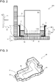
Fig. 3 : lafigure 3 illustre une entretoise du module d'isolation électrique selon un mode de réalisation de l'invention ; et -
Fig. 4 : lafigure 4 illustre l'entretoise selon une perspective différente de celle de lafigure 3 .
-
Fig. 1 : thefigure 1 illustrates the longitudinal section of conventional electrical equipment comprising a thermal pad; -
Fig. 2 : thefigure 2 illustrates the longitudinal section of an electrical insulation module installed in electrical equipment, according to one embodiment of the invention; -
Fig. 3 : thefigure 3 illustrates a spacer of the electrical insulation module according to one embodiment of the invention; and -
Fig. 4 : thefigure 4 illustrates the spacer from a different perspective than thefigure 3 .
Il faut noter que les figures exposent l'invention de manière détaillée pour mettre en œuvre l'invention, lesdites figures pouvant bien entendu servir à mieux définir l'invention le cas échéant.It should be noted that the figures set out the invention in detail in order to implement the invention, said figures being able of course to serve to better define the invention if necessary.
La
Le module d'isolation électrique 5, étant en matériau isolant électrique, est configuré pour définir au moins une ligne de fuite 71, 72 de l'équipement électrique 200, la longueur de ladite au moins une ligne de fuite étant augmentée par rapport à l'art antérieur. Le module d'isolation électrique 5 sera décrit plus en détail dans les paragraphes suivants.The
Le boîtier comprend au moins un logement configuré pour héberger l'au moins un composant électrique 101. La
Dans un mode de réalisation, le boîtier de l'équipement électrique 200 comprend un seul logement. Dans ce cas, la plaque de support 15 est une plaque de base dudit boîtier. La paroi latérale 16 est une paroi latérale du boîtier. Dans un mode de réalisation alternatif, le boîtier comprend plusieurs logements. Au moins un de ces logements dont la paroi latérale 16 et/ou la plaque de support 15 sont respectivement une paroi de cloisonnement et/ou une plaque intermédiaire installées à l'intérieur du boîtier de l'équipement électrique 200. Ladite paroi de cloisonnement est de préférence parallèle à la paroi latérale du boîtier. Ladite plaque intermédiaire, installée entre une ouverture supérieure du boîtier et la plaque de base du boîtier, est de préférence parallèle à la plaque de base du boîtier.In one embodiment, the housing of the
Selon un exemple, les épaisseurs de la paroi latérale 16 et de la plaque de support 15 sont respectivement 4 mm (millimètre) et 4 mm. De plus, dans le présent mode de réalisation, le boîtier et le logement présentent respectivement une forme de parallélépipède rectangle. De manière alternative, le boîtier et le logement peuvent présenter une autre forme, par exemple un cylindre.According to one example, the thicknesses of the side wall 16 and of the
La paroi latérale 16 est de préférence orthogonale à la plaque de support 15 ; c'est-à-dire un angle interne entre la plaque de support 15 et la paroi latérale 16 est égal à 90 degrés. De manière alternative, ledit angle interne peut être compris entre 80 et 110 degrés.The side wall 16 is preferably orthogonal to the
Dans un mode de réalisation, l'au moins un composant électrique 101 est configuré pour présenter un potentiel électrique. Le composant électrique 101 est par exemple un élément capacitif, une bobine, une capacité, ou un transformateur. Le composant électrique 101 peut être un composant électrique haute tension. La haute tension désigne de préférence une tension supérieure à 60V (Volts) voire supérieure à 80V, voire même supérieure à 100V. L'équipement électrique 200 peut être un onduleur, un convertisseur tension continu-continu (« DC-to-DC Voltage converter» en anglais) ou un chargeur électrique, notamment configurés pour être embarqués dans un véhicule. Dans un mode de réalisation, le composant électrique 101 comporte une enveloppe isolante. La partie du composant électrique 101 en vis-à-vis d'une paroi de fond 51 d'une entretoise 50 (décrite plus en détail ci-après) et en contact avec un coussin thermique 60 (décrit plus en détail ci-après) est dépourvue de l'enveloppe isolante afin de favoriser l'échange thermique. La partie du composant électrique 101 en vis-à-vis de la paroi de fond 51 comprend notamment une partie conductrice thermique, notamment métallique.In one embodiment, the at least one
De manière préférentielle, il existe un premier espacement 31 entre la paroi latérale 16 du logement 12 et l'au moins un composant électrique 101. Le premier espacement 31 est avantageusement compris entre 0 mm et 10 mm. La longueur du premier espacement 31 est supérieure ou égale à une distance d'isolation électrique par l'air.Preferably, there is a
Préférentiellement, il existe un deuxième espacement 32 entre la plaque de support 15 du logement 12 et l'au moins un composant électrique 101. Le deuxième espacement 32 est avantageusement compris entre 0.5 mm et 5 mm. Dans un mode de réalisation préférentiel où ledit coussin thermique 60 est utilisé, le deuxième espacement 32 est largement rempli par l'épaisseur du coussin thermique 60.Preferably, there is a
Le module d'isolation électrique 5 comprend ladite entretoise 50. Les
La paroi périphérique 52 comprend de préférence un rebord 58, notamment configuré pour permettre de saisir et manipuler l'entretoise 50. Le rebord 58 est formé à une deuxième extrémité de la paroi périphérique 52 qui est distale par rapport à une première extrémité de la paroi périphérique 52 depuis laquelle la paroi de fond 51 s'étend. De manière préférentielle, l'entretoise 50 est formé d'un seul tenant. De plus, l'entretoise 50 peut être fabriquée par la réalisation d'un procédé de fabrication par emboutissage, et le rebord 58 peut donc être imposé par un processus d'emboutissage. Le rebord 58 est compté ainsi dans la première ligne de fuite 71, ce qui permet donc de réduire la hauteur de l'entretoise 50, notamment la distance entre la première extrémité de la paroi périphérique 52 et la deuxième extrémité de la paroi périphérique 52.The
Ladite cavité de réception, définie par la paroi de fond 51 et la paroi périphérique 52, est configurée pour recevoir au moins une portion 101a de l'au moins un composant électrique 101, comme par exemple illustré en
Le matériau de l'entretoise 50 est de préférence en plastique/matière isolante. Les épaisseurs de la paroi de fond 51 et de la paroi périphérique 52 sont respectivement de préférence très fines, par exemple entre 0.25 mm et 1.2 mm. Ladite cavité de réception est de préférence une cavité avec un fond plat. La hauteur de le paroi périphérique 52, notamment la distance entre la première extrémité de la paroi périphérique 52 et la deuxième extrémité de la paroi périphérique 52, doit être au minimum 10 mm. La forme et le volume de la cavité de réception sont déterminées en fonctions de la forme et du volume de la portion 101a de l'au moins un composant électrique 101.The material of the
Dans un mode de réalisation préférentiel illustré en
Le coussin thermique 60 est de préférence fait d'un matériau déformable voire élastique. De manière avantageuse, le matériau du coussin thermique 60 est un matériau silicone ou céramique. L'épaisseur du coussin thermique 60 en état libre est comprise de préférence entre 0.5 mm et 10 mm. L'épaisseur du coussin thermique 60 en état compressé est comprise de préférence entre 0.25 mm et 5 mm. Dans son état compressé, le coussin thermique 60 remplit le deuxième espacement 32 (comme mentionnée précédemment) pour venir contre la plaque de support 15.The
L'au moins une ligne de fuite, par exemple les lignes de fuite 71 et 72, est déterminée en fonction d'une surface correspondant à une portion de la paroi de fond 51, et/ou d'au moins une portion de la paroi périphérique 52. Ladite surface correspondant à une portion de la paroi de fond 51 peut être une surface de la paroi de fond 51 elle-même, ou une autre surface qui n'appartient pas à, mais est parallèle à la paroi de fond 51, par exemple une surface externe supérieure du coussin thermique 60 située entre le composant électrique 101 et la paroi périphérique 52.The at least one creepage line, for example the
Plus précisément, l'au moins une ligne de fuite est déterminée en fonction d'au moins une des surfaces suivantes définies par la présence du module d'isolation électrique 5, car un éventuel courant de fuite serait contraint de parcourir ces surfaces : une surface externe supérieure du coussin thermique 60 située entre le composant électrique 101 et la paroi périphérique 52 ; une première surface de contact entre le coussin thermique 60 et ladite paroi périphérique 52 ; une troisième surface de contact entre le coussin thermique 60 et ladite paroi de fond 51 ; une surface de la paroi périphérique 52 formant une surface interne (c'est-à-dire tournée vers la cavité de réception) de la paroi périphérique 52 dépourvue du coussin thermique 60, c'est-à-dire une surface interne de la paroi périphérique 52 située entre le coussin thermique 60 et la deuxième extrémité de la paroi périphérique 52 ; une surface externe (c'est-à-dire opposée à la cavité interne) de la paroi périphérique 52 qui s'étend notamment entre ladite deuxième extrémité et la plaque de support 15 ; le cas échant, une surface du rebord 58. Plus les surfaces disponibles sont utilisées, plus la longueur de la ligne de fuite augmente.More precisely, the at least one creepage line is determined as a function of at least one of the following surfaces defined by the presence of the
Comme illustré par exemple en
Par ailleurs, une deuxième ligne de fuite 72 est déterminée en fonction de l'ensemble des surfaces suivantes : la surface externe supérieure du coussin thermique 60 située entre le composant électrique 101 et la paroi périphérique 52 ; ladite première surface de contact entre le coussin thermique 60 et ladite paroi périphérique 52 ; et ladite troisième surface de contact entre le coussin thermique 60 et ladite paroi de fond 51. La deuxième ligne de fuite 72 comprend ainsi une dimension correspondant au parcours de la surface externe supérieure du coussin thermique 60, une dimension correspondant au parcours de la deuxième surface de contact et une dimension correspondant au parcours de la troisième surface de contact.Furthermore, a
Par rapport à la ligne de fuite illustrée dans l'art antérieur, l'invention permet de largement rallonger les lignes de fuite 71, 72 en utilisant lesdites surfaces définies par la présence du module d'isolation électrique 5. De plus, l'entretoise 50 est très léger et facile à monter à l'équipement électrique 200, ce qui ne complique donc pas la fabrication de l'équipement électrique 200.Compared to the creepage line illustrated in the prior art, the invention makes it possible to greatly lengthen the
L'invention propose donc une solution aisée à mettre en œuvre et non coûteuse qui, d'une part, augmente la longueur de la ligne de fuite sans augmentation de la taille d'un équipement électrique et, d'autre part, améliore la dissipation de la chaleur générée lors du fonctionnement de l'équipement électrique.The invention therefore proposes a solution that is easy to implement and inexpensive which, on the one hand, increases the length of the creepage line without increasing the size of an item of equipment. electrical and, on the other hand, improves the dissipation of heat generated during the operation of electrical equipment.
L'invention n'est pas limitée aux modes de réalisation précédemment décrits mais s'étend à tout mode de réalisation conforme à son esprit.The invention is not limited to the embodiments described above but extends to any embodiment in accordance with its spirit.
Notamment, dans une variante, la paroi de fond 51 ne comprend pas d'ouverture. En particulier, la paroi de fond 51 forme alors une paroi pleine bordée par la paroi latérale 16. Le module d'isolation électrique 5 présente alors la première ligne de fuite 71.In particular, in a variant, the
En particulier, le composant électrique 101 peut alors venir directement sur la paroi de fond 51. Le module d'isolation électrique 5 est alors dépourvu du coussin thermique 60. La première ligne de fuite 71 peut alors comprendre une surface interne de la paroi de fond 51 située entre le composant électrique 101 et la paroi latérale 52, lorsque le composant électrique 101 est à distance de la paroi latérale 52. Le composant électrique 101 peut alternativement venir contre la paroi latérale 52 de sorte que la première ligne de fuite 71 comprend la surface interne de la paroi périphérique 52 et la surface externe de la paroi périphérique 52 qui s'étend notamment entre la deuxième extrémité de la paroi périphérique 52 et la plaque de support 15.In particular, the
Claims (10)
dans laquelle :
in which :
Applications Claiming Priority (1)
| Application Number | Priority Date | Filing Date | Title |
|---|---|---|---|
| FR1914292A FR3104890B1 (en) | 2019-12-12 | 2019-12-12 | ELECTRICAL INSULATION MODULE FOR HIGH VOLTAGE ELECTRICAL EQUIPMENT |
Publications (1)
| Publication Number | Publication Date |
|---|---|
| EP3836765A1 true EP3836765A1 (en) | 2021-06-16 |
Family
ID=69903422
Family Applications (1)
| Application Number | Title | Priority Date | Filing Date |
|---|---|---|---|
| EP20210388.3A Pending EP3836765A1 (en) | 2019-12-12 | 2020-11-27 | Electrical insulation module for high-voltage electrical equipment |
Country Status (5)
| Country | Link |
|---|---|
| US (1) | US11330730B2 (en) |
| EP (1) | EP3836765A1 (en) |
| KR (1) | KR20210075012A (en) |
| CN (1) | CN112993771A (en) |
| FR (1) | FR3104890B1 (en) |
Families Citing this family (1)
| Publication number | Priority date | Publication date | Assignee | Title |
|---|---|---|---|---|
| US11333730B2 (en) | 2017-10-25 | 2022-05-17 | The Board Of Trustees Of The Leland Stanford Junior University | Systems and methods for mapping neuronal circuitry and clinical applications thereof |
Citations (4)
| Publication number | Priority date | Publication date | Assignee | Title |
|---|---|---|---|---|
| US3803457A (en) * | 1972-05-09 | 1974-04-09 | Nichicon Capacitor Ltd | Block type electrolytic capacitor |
| DE102010043445B3 (en) * | 2010-11-05 | 2012-04-19 | Semikron Elektronik Gmbh & Co. Kg | Capacitor assembly for power electronic apparatus, has spacer and electrical isolating capping material that are arranged such that capacitor is in non contact with metal structure |
| WO2015059552A1 (en) * | 2013-10-24 | 2015-04-30 | Toyota Jidosha Kabushiki Kaisha | Power converter |
| DE102016222823A1 (en) * | 2016-11-18 | 2018-05-24 | Audi Ag | Control device for a motor vehicle and motor vehicle |
Family Cites Families (9)
| Publication number | Priority date | Publication date | Assignee | Title |
|---|---|---|---|---|
| JP4115050B2 (en) * | 1998-10-07 | 2008-07-09 | キヤノン株式会社 | Electron beam apparatus and spacer manufacturing method |
| JP2005285474A (en) * | 2004-03-29 | 2005-10-13 | Toshiba Corp | Image display device and its manufacturing method |
| KR20070044579A (en) * | 2005-10-25 | 2007-04-30 | 삼성에스디아이 주식회사 | Spacer and electron emission display device having the spacer |
| JP2008010399A (en) * | 2006-05-31 | 2008-01-17 | Canon Inc | Image display device |
| JP2012509665A (en) * | 2008-11-26 | 2012-04-26 | メルク・シャープ・エンド・ドーム・コーポレイション | Polypeptides that induce a protective immune response against STAPHYLOCOCUSAUREUS |
| US8736062B2 (en) * | 2012-08-16 | 2014-05-27 | Infineon Technologies Ag | Pad sidewall spacers and method of making pad sidewall spacers |
| JP6422592B2 (en) * | 2015-10-28 | 2018-11-14 | 三菱電機株式会社 | Power converter |
| JP2019057634A (en) * | 2017-09-21 | 2019-04-11 | 東芝メモリ株式会社 | Manufacturing method for semiconductor device |
| WO2019181508A1 (en) * | 2018-03-23 | 2019-09-26 | 株式会社Gsユアサ | Power storage device |
-
2019
- 2019-12-12 FR FR1914292A patent/FR3104890B1/en active Active
-
2020
- 2020-11-27 EP EP20210388.3A patent/EP3836765A1/en active Pending
- 2020-12-04 KR KR1020200168275A patent/KR20210075012A/en unknown
- 2020-12-09 US US17/116,452 patent/US11330730B2/en active Active
- 2020-12-10 CN CN202011434374.6A patent/CN112993771A/en active Pending
Patent Citations (4)
| Publication number | Priority date | Publication date | Assignee | Title |
|---|---|---|---|---|
| US3803457A (en) * | 1972-05-09 | 1974-04-09 | Nichicon Capacitor Ltd | Block type electrolytic capacitor |
| DE102010043445B3 (en) * | 2010-11-05 | 2012-04-19 | Semikron Elektronik Gmbh & Co. Kg | Capacitor assembly for power electronic apparatus, has spacer and electrical isolating capping material that are arranged such that capacitor is in non contact with metal structure |
| WO2015059552A1 (en) * | 2013-10-24 | 2015-04-30 | Toyota Jidosha Kabushiki Kaisha | Power converter |
| DE102016222823A1 (en) * | 2016-11-18 | 2018-05-24 | Audi Ag | Control device for a motor vehicle and motor vehicle |
Also Published As
| Publication number | Publication date |
|---|---|
| CN112993771A (en) | 2021-06-18 |
| US20210185841A1 (en) | 2021-06-17 |
| US11330730B2 (en) | 2022-05-10 |
| KR20210075012A (en) | 2021-06-22 |
| FR3104890B1 (en) | 2022-06-24 |
| FR3104890A1 (en) | 2021-06-18 |
Similar Documents
| Publication | Publication Date | Title |
|---|---|---|
| EP2145360B1 (en) | Module for an electric energy storage assembly | |
| CA2685199C (en) | Modules for electrical energy storage assemblies enabling the detection of aging in the said assemblies | |
| EP3547001A1 (en) | Optical device for vehicle comprising a heating element | |
| EP2394878B1 (en) | Railway vehicle and corresponding manufacturing method | |
| EP3621093B1 (en) | Capacitive block comprising a heat sink | |
| EP3056070B1 (en) | Electric module, electric system comprising such an electric module, and corresponding production methods | |
| WO2020084479A1 (en) | Connection device for a vehicle equipped with a temperature sensor | |
| EP3836765A1 (en) | Electrical insulation module for high-voltage electrical equipment | |
| WO2013113691A1 (en) | Positioning spacer, energy storage module using said spacer and method for assembling the module | |
| FR2581827A1 (en) | CONNECTION STRIP FOR THE MANUFACTURE OF DIRECT-REPORT ELECTRICAL COMPONENTS AND METHOD OF MANUFACTURING THESE COMPONENTS | |
| EP3888154A1 (en) | Battery case and modular battery system | |
| FR2824231A1 (en) | DEVICE FOR MOUNTING ELECTRICAL AND / OR ELECTRONIC COMPONENTS ON A PRINTED CIRCUIT BOARD | |
| EP2536261A1 (en) | Electronic power module with integrated capacitance | |
| EP3535791A1 (en) | Unitary module for a battery pack, and battery pack | |
| EP3840557A1 (en) | Electrical equipment comprising an electrical connection bar cooled by two surfaces of a heat sink | |
| FR2981537A1 (en) | MECHANICAL MAINTENANCE SYSTEM, ASSEMBLY COMPRISING SUCH A SYSTEM AND AN ELECTRONIC BOARD AND METHOD OF ASSEMBLING ON A SURFACE OF SUCH A SYSTEM AND SUCH A CARD | |
| EP3667688B1 (en) | Electrical assembly comprising a capacitive element | |
| FR2857819A1 (en) | HYPERFREQUENCY HYBRID CIRCUIT DEVICE WITH SHIELD BY ELASTIC CONTACT MEMBER (S) | |
| FR3127080A1 (en) | Electrical connection bar | |
| EP3902381A1 (en) | Electrical assembly mounted on a support | |
| EP3672382A1 (en) | Pressing element, assembly and electrical equipment | |
| FR3091012A1 (en) | ASSEMBLY COMPRISING AN ELECTRICAL DEVICE, A PLATING MEMBER AND A HOLDING PIECE FOR THE PLATING MEMBER | |
| FR3055747A1 (en) | FEMALE ELECTRICAL CONTACT CAGE | |
| FR3081621A1 (en) | DEVICE FOR PERPENDICULAR COUPLING OF AN ELECTRICAL BEAM TO AN ELECTRICALLY CONDUCTIVE BAR SET (S) | |
| FR3056726A1 (en) | UNITARY TUBULAR MODULE FOR MOTOR VEHICLE WITH THERMAL MOTOR, AND THERMOELECTRIC GENERATOR INCORPORATING SEVERAL OF THESE MODULES |
Legal Events
| Date | Code | Title | Description |
|---|---|---|---|
| PUAI | Public reference made under article 153(3) epc to a published international application that has entered the european phase |
Free format text: ORIGINAL CODE: 0009012 |
|
| STAA | Information on the status of an ep patent application or granted ep patent |
Free format text: STATUS: THE APPLICATION HAS BEEN PUBLISHED |
|
| AK | Designated contracting states |
Kind code of ref document: A1 Designated state(s): AL AT BE BG CH CY CZ DE DK EE ES FI FR GB GR HR HU IE IS IT LI LT LU LV MC MK MT NL NO PL PT RO RS SE SI SK SM TR |
|
| STAA | Information on the status of an ep patent application or granted ep patent |
Free format text: STATUS: REQUEST FOR EXAMINATION WAS MADE |
|
| 17P | Request for examination filed |
Effective date: 20211202 |
|
| RBV | Designated contracting states (corrected) |
Designated state(s): AL AT BE BG CH CY CZ DE DK EE ES FI FR GB GR HR HU IE IS IT LI LT LU LV MC MK MT NL NO PL PT RO RS SE SI SK SM TR |
|
| RAP3 | Party data changed (applicant data changed or rights of an application transferred) |
Owner name: VALEO EAUTOMOTIVE FRANCE SAS |
|
| GRAP | Despatch of communication of intention to grant a patent |
Free format text: ORIGINAL CODE: EPIDOSNIGR1 |
|
| STAA | Information on the status of an ep patent application or granted ep patent |
Free format text: STATUS: GRANT OF PATENT IS INTENDED |
|
| RIC1 | Information provided on ipc code assigned before grant |
Ipc: H05K 7/12 20060101ALI20230524BHEP Ipc: H05K 7/14 20060101AFI20230524BHEP |
|
| INTG | Intention to grant announced |
Effective date: 20230616 |
|
| P01 | Opt-out of the competence of the unified patent court (upc) registered |
Effective date: 20230629 |
|
| GRAJ | Information related to disapproval of communication of intention to grant by the applicant or resumption of examination proceedings by the epo deleted |
Free format text: ORIGINAL CODE: EPIDOSDIGR1 |
|
| STAA | Information on the status of an ep patent application or granted ep patent |
Free format text: STATUS: REQUEST FOR EXAMINATION WAS MADE |
|
| GRAJ | Information related to disapproval of communication of intention to grant by the applicant or resumption of examination proceedings by the epo deleted |
Free format text: ORIGINAL CODE: EPIDOSDIGR1 |
|
| GRAL | Information related to payment of fee for publishing/printing deleted |
Free format text: ORIGINAL CODE: EPIDOSDIGR3 |
|
| GRAS | Grant fee paid |
Free format text: ORIGINAL CODE: EPIDOSNIGR3 |
|
| GRAP | Despatch of communication of intention to grant a patent |
Free format text: ORIGINAL CODE: EPIDOSNIGR1 |
|
| STAA | Information on the status of an ep patent application or granted ep patent |
Free format text: STATUS: GRANT OF PATENT IS INTENDED |
|
| INTC | Intention to grant announced (deleted) | ||
| INTG | Intention to grant announced |
Effective date: 20231115 |
|
| GRAJ | Information related to disapproval of communication of intention to grant by the applicant or resumption of examination proceedings by the epo deleted |
Free format text: ORIGINAL CODE: EPIDOSDIGR1 |
|
| GRAL | Information related to payment of fee for publishing/printing deleted |
Free format text: ORIGINAL CODE: EPIDOSDIGR3 |
|
| STAA | Information on the status of an ep patent application or granted ep patent |
Free format text: STATUS: REQUEST FOR EXAMINATION WAS MADE |
|
| GRAP | Despatch of communication of intention to grant a patent |
Free format text: ORIGINAL CODE: EPIDOSNIGR1 |
|
| STAA | Information on the status of an ep patent application or granted ep patent |
Free format text: STATUS: GRANT OF PATENT IS INTENDED |
|
| INTC | Intention to grant announced (deleted) | ||
| INTG | Intention to grant announced |
Effective date: 20240321 |