EP3836710B1 - Kommunikationsverfahren und -vorrichtung - Google Patents
Kommunikationsverfahren und -vorrichtung Download PDFInfo
- Publication number
- EP3836710B1 EP3836710B1 EP19848753.0A EP19848753A EP3836710B1 EP 3836710 B1 EP3836710 B1 EP 3836710B1 EP 19848753 A EP19848753 A EP 19848753A EP 3836710 B1 EP3836710 B1 EP 3836710B1
- Authority
- EP
- European Patent Office
- Prior art keywords
- ack
- csi
- frequency hopping
- uci
- hopping resource
- Prior art date
- Legal status (The legal status is an assumption and is not a legal conclusion. Google has not performed a legal analysis and makes no representation as to the accuracy of the status listed.)
- Active
Links
Images


Classifications
-
- H—ELECTRICITY
- H04—ELECTRIC COMMUNICATION TECHNIQUE
- H04W—WIRELESS COMMUNICATION NETWORKS
- H04W72/00—Local resource management
- H04W72/12—Wireless traffic scheduling
- H04W72/1263—Mapping of traffic onto schedule, e.g. scheduled allocation or multiplexing of flows
-
- H—ELECTRICITY
- H04—ELECTRIC COMMUNICATION TECHNIQUE
- H04L—TRANSMISSION OF DIGITAL INFORMATION, e.g. TELEGRAPHIC COMMUNICATION
- H04L1/00—Arrangements for detecting or preventing errors in the information received
- H04L1/12—Arrangements for detecting or preventing errors in the information received by using return channel
- H04L1/16—Arrangements for detecting or preventing errors in the information received by using return channel in which the return channel carries supervisory signals, e.g. repetition request signals
- H04L1/1607—Details of the supervisory signal
- H04L1/1671—Details of the supervisory signal the supervisory signal being transmitted together with control information
-
- H—ELECTRICITY
- H04—ELECTRIC COMMUNICATION TECHNIQUE
- H04B—TRANSMISSION
- H04B7/00—Radio transmission systems, i.e. using radiation field
- H04B7/02—Diversity systems; Multi-antenna system, i.e. transmission or reception using multiple antennas
- H04B7/04—Diversity systems; Multi-antenna system, i.e. transmission or reception using multiple antennas using two or more spaced independent antennas
- H04B7/06—Diversity systems; Multi-antenna system, i.e. transmission or reception using multiple antennas using two or more spaced independent antennas at the transmitting station
- H04B7/0613—Diversity systems; Multi-antenna system, i.e. transmission or reception using multiple antennas using two or more spaced independent antennas at the transmitting station using simultaneous transmission
- H04B7/0615—Diversity systems; Multi-antenna system, i.e. transmission or reception using multiple antennas using two or more spaced independent antennas at the transmitting station using simultaneous transmission of weighted versions of same signal
- H04B7/0619—Diversity systems; Multi-antenna system, i.e. transmission or reception using multiple antennas using two or more spaced independent antennas at the transmitting station using simultaneous transmission of weighted versions of same signal using feedback from receiving side
- H04B7/0621—Feedback content
- H04B7/0626—Channel coefficients, e.g. channel state information [CSI]
-
- H—ELECTRICITY
- H04—ELECTRIC COMMUNICATION TECHNIQUE
- H04L—TRANSMISSION OF DIGITAL INFORMATION, e.g. TELEGRAPHIC COMMUNICATION
- H04L1/00—Arrangements for detecting or preventing errors in the information received
- H04L1/12—Arrangements for detecting or preventing errors in the information received by using return channel
- H04L1/16—Arrangements for detecting or preventing errors in the information received by using return channel in which the return channel carries supervisory signals, e.g. repetition request signals
- H04L1/18—Automatic repetition systems, e.g. Van Duuren systems
- H04L1/1812—Hybrid protocols; Hybrid automatic repeat request [HARQ]
- H04L1/1819—Hybrid protocols; Hybrid automatic repeat request [HARQ] with retransmission of additional or different redundancy
-
- H—ELECTRICITY
- H04—ELECTRIC COMMUNICATION TECHNIQUE
- H04L—TRANSMISSION OF DIGITAL INFORMATION, e.g. TELEGRAPHIC COMMUNICATION
- H04L5/00—Arrangements affording multiple use of the transmission path
- H04L5/0001—Arrangements for dividing the transmission path
- H04L5/0003—Two-dimensional division
- H04L5/0005—Time-frequency
- H04L5/0007—Time-frequency the frequencies being orthogonal, e.g. OFDM(A) or DMT
- H04L5/0012—Hopping in multicarrier systems
-
- H—ELECTRICITY
- H04—ELECTRIC COMMUNICATION TECHNIQUE
- H04L—TRANSMISSION OF DIGITAL INFORMATION, e.g. TELEGRAPHIC COMMUNICATION
- H04L5/00—Arrangements affording multiple use of the transmission path
- H04L5/003—Arrangements for allocating sub-channels of the transmission path
- H04L5/0044—Allocation of payload; Allocation of data channels, e.g. PDSCH or PUSCH
-
- H—ELECTRICITY
- H04—ELECTRIC COMMUNICATION TECHNIQUE
- H04L—TRANSMISSION OF DIGITAL INFORMATION, e.g. TELEGRAPHIC COMMUNICATION
- H04L5/00—Arrangements affording multiple use of the transmission path
- H04L5/003—Arrangements for allocating sub-channels of the transmission path
- H04L5/0048—Allocation of pilot signals, i.e. of signals known to the receiver
- H04L5/0051—Allocation of pilot signals, i.e. of signals known to the receiver of dedicated pilots, i.e. pilots destined for a single user or terminal
-
- H—ELECTRICITY
- H04—ELECTRIC COMMUNICATION TECHNIQUE
- H04L—TRANSMISSION OF DIGITAL INFORMATION, e.g. TELEGRAPHIC COMMUNICATION
- H04L5/00—Arrangements affording multiple use of the transmission path
- H04L5/003—Arrangements for allocating sub-channels of the transmission path
- H04L5/0053—Allocation of signalling, i.e. of overhead other than pilot signals
- H04L5/0055—Physical resource allocation for ACK/NACK
-
- H—ELECTRICITY
- H04—ELECTRIC COMMUNICATION TECHNIQUE
- H04W—WIRELESS COMMUNICATION NETWORKS
- H04W28/00—Network traffic management; Network resource management
- H04W28/16—Central resource management; Negotiation of resources or communication parameters, e.g. negotiating bandwidth or QoS [Quality of Service]
- H04W28/26—Resource reservation
-
- H—ELECTRICITY
- H04—ELECTRIC COMMUNICATION TECHNIQUE
- H04W—WIRELESS COMMUNICATION NETWORKS
- H04W72/00—Local resource management
- H04W72/04—Wireless resource allocation
- H04W72/044—Wireless resource allocation based on the type of the allocated resource
- H04W72/0446—Resources in time domain, e.g. slots or frames
-
- H—ELECTRICITY
- H04—ELECTRIC COMMUNICATION TECHNIQUE
- H04W—WIRELESS COMMUNICATION NETWORKS
- H04W72/00—Local resource management
- H04W72/20—Control channels or signalling for resource management
-
- H—ELECTRICITY
- H04—ELECTRIC COMMUNICATION TECHNIQUE
- H04W—WIRELESS COMMUNICATION NETWORKS
- H04W72/00—Local resource management
- H04W72/20—Control channels or signalling for resource management
- H04W72/21—Control channels or signalling for resource management in the uplink direction of a wireless link, i.e. towards the network
-
- H—ELECTRICITY
- H04—ELECTRIC COMMUNICATION TECHNIQUE
- H04L—TRANSMISSION OF DIGITAL INFORMATION, e.g. TELEGRAPHIC COMMUNICATION
- H04L1/00—Arrangements for detecting or preventing errors in the information received
- H04L1/004—Arrangements for detecting or preventing errors in the information received by using forward error control
- H04L1/0072—Error control for data other than payload data, e.g. control data
Definitions
- This application relates to the communications field, and in particular, to a communication method and a communications apparatus.
- uplink control information uplink control information
- PUSCH physical uplink shared channel
- the sent UCI includes a hybrid automatic repeat request-acknowledgement (hybrid automatic repeat request-acknowledgement, HARQ-ACK), a channel state information part 1 (channel state information part 1, CSI-part1), and a channel state information part 2 (CSI-part2).
- HARQ-ACK hybrid automatic repeat request-acknowledgement
- CSI-part1 channel state information part 1, CSI-part1
- CSI-part2 channel state information part 2
- the PUSCH may be divided into two parts in time domain, where the two parts are respectively referred to as a first hop (hop 1) and a second hop (hop 2).
- hop 1 and the hop 2 are generally far away from each other and at least do not exactly overlap.
- the HARQ-ACK, the CSI-part1, and the CSI-part2 are also mapped to the hop 1 and the hop 2 according to a preset rule.
- information in the CSI-part1 mapped to the frequency hopping resources is incompletely sent, that is, a part of the CSI-part1 fails to be transmitted. This adversely affects application of UCI transmission through frequency hopping in the UCI-only scenario.
- R1-1806735 "Corrections on UCI Multiplexing in PUSCH" presents formulae on page 2 for computation of G-CSI-part1 (1) and G-CSI-part2 (1) in different cases.
- This application provides a communication method and a communications apparatus.
- a CSI-partl mapping rule is changed, to resolve a problem that due to UCI transmission through frequency hopping in a UCI-only scenario, information in CSI-partl is incompletely sent.
- a communication method includes: receiving downlink control information, where the downlink control information is used to schedule a PUSCH, the PUSCH is used to carry uplink control information, UCI, without uplink shared channel, UL-SCH, the PUSCH includes a first frequency hopping resource and a second frequency hopping resource, and a time-domain start symbol of the first frequency hopping resource is before a time-domain start symbol of the second frequency hopping resource; and sending first UCI on the PUSCH, where the first UCI includes at least one of an HARQ-ACK, CSI-partl, and CSI-part2, where a quantity of coded bits that can be mapped onto reserved REs in the first frequency hopping resource is a first value, a quantity of coded bits that can be mapped onto reserved REs in the second frequency hopping resource is a second value, the first value is not less than the second value, and the reserved REs in the first frequency hopping resource and the reserved REs in the second frequency hopping resource are reserved
- a peer device of the device that performs the foregoing method may correspondingly perform steps of sending the downlink control information and receiving the first UCI on the PUSCH.
- the PUSCH includes a first frequency hopping resource and a second frequency hopping resource means that when a frequency hopping identifier field in uplink grant (UL grant) DCI indicated by a network device enables frequency hopping for the PUSCH, a time-frequency domain resource of the PUSCH in a first hop and a time-frequency domain resource of the PUSCH in a second hop are respectively referred to as the first frequency hopping resource and the second frequency hopping resource.
- a value of a quantity of coded bits mapped onto a specific quantity of REs of the PUSCH is equal to the quantity of REs multiplied by a quantity of transmission layers of the PUSCH and then multiplied by a modulation order of UCI potentially transmitted on the PUSCH.
- a reason that information in the CSI-partl is incompletely sent is that a quantity of coded bits that are of the CSI-part1 and that are mapped onto the second frequency hopping resource is relatively small. In other words, a quantity of REs on the second frequency hopping resource that are used to map the CSI-part1 is relatively small, and consequently, the CSI-partl cannot be all mapped onto the second frequency hopping resource.
- this application reduces a quantity of coded bits that are capable of being mapped onto reserved REs in the second frequency hopping resource, thereby increasing a quantity of REs that are in the second frequency hopping resource and that are used to map the CSI-partl. This resolves a problem that due to UCI transmission through frequency hopping in a UCI-only scenario, information in the CSI-partl is incompletely sent.
- the method further includes: determining a first quantity G rvd ACK of coded bits, where G rvd ACK is a sum of the quantities of coded bits mapped onto the reserved REs in the first frequency hopping resource and the second frequency hopping resource, and both the first value and the second value are determined based on G rvd ACK .
- the "sum of the quantities of coded bits mapped onto the reserved REs in the first frequency hopping resource and the second frequency hopping resource” refers to a sum of a quantity of coded bits that are capable of being mapped onto the reserved REs in the first frequency hopping resource and a quantity of coded bits that are capable of being mapped onto the reserved REs in the second frequency hopping resource, but should not be understood as a sum of a quantity of coded bits actually mapped onto the reserved REs in the first frequency hopping resource and a quantity of coded bits actually mapped onto the reserved REs in the second frequency hopping resource.
- the first value is G rvd ACK 1
- G rvd ACK 1 N L ⁇ Q m ⁇ ⁇ G rvd ACK / 2 ⁇ N L ⁇ Q m ⁇
- the second value is G rvd ACK 2
- G rvd ACK 2 N L ⁇ Q m ⁇ ⁇ G rvd ACK / 2 ⁇ N L ⁇ Q m ⁇
- N L is a quantity of transmission layers of the PUSCH
- Q m is a modulation order of the first UCI, namely, a modulation order of the UCI transmitted on the PUSCH.
- G rvd ACK 1 N L ⁇ Q m ⁇ ⁇ G rvd ACK / 2 ⁇ N L ⁇ Q m ⁇
- G rvd ACK 2 G rvd ACK ⁇ G rvd ACK 1
- G rvd ACK 2 N L ⁇ Q m ⁇ ⁇ G rvd ACK / 2 ⁇ N L ⁇ Q m ⁇
- G rvd ACK 1 G rvd ACK ⁇ G rvd ACK 2 .
- the method further includes: determining a quantity G ACK of coded bits of the HARQ-ACK in the first UCI, where a quantity of coded bits that are of the HARQ-ACK in the first UCI and that are mapped onto the first frequency hopping resource is G ACK (1), and a value of G ACK (1) is a smaller one of the following two values: a quantity of coded bits mapped onto an RE that is after a first group of consecutive demodulation reference signal (demodulation reference signal, DMRS) symbols on the first frequency hopping resource and that are capable of being used to carry data, and a third value that is determined based on G ACK .
- demodulation reference signal demodulation reference signal
- a terminal device may determine, based on the bearer capability of the first frequency hopping resource, the quantity of coded bits that are of the HARQ-ACK in the first UCI and that are mapped onto the first frequency hopping resource.
- the terminal device may determine, based on the quantity (for example, N L ⁇ Q m ⁇ ⁇ G rvd ACK / 2 ⁇ N L ⁇ Q m ⁇ ) of coded bits that are of the HARQ-ACK in the first UCI and that are capable of being mapped onto the first frequency hopping resource, the quantity of coded bits that are of the HARQ-ACK and that are mapped onto the first frequency hopping resource.
- the terminal device may determine, based on the quantity (for example, N L ⁇ Q m ⁇ ⁇ G rvd ACK / 2 ⁇ N L ⁇ Q m ) of coded bits that are of the HARQ-ACK in the first UCI and that are capable of being mapped onto the first frequency hopping resource.
- a value of the quantity of coded bits mapped onto the RE that is after the first group of consecutive DMRS symbols on the first frequency hopping resource and that are capable of being used to carry data is equal to M 3 ⁇ N L ⁇ Q m , where M 3 is a quantity of REs that are after the first group of consecutive DMRS symbols on the first frequency hopping resource and that are capable of being used to carry data, N L is the quantity of transmission layers of the PUSCH, Q m is the modulation order of the first UCI, and the third value is N L ⁇ Q m ⁇ ⁇ G ACK /(2 ⁇ N L ⁇ Q m ) ⁇ .
- the quantity of bits of the HARQ-ACK in the first UCI is not greater than 2.
- G ACK (1) min( N L ⁇ Q m ⁇ ⁇ G ACK /(2 ⁇ N L ⁇ Q m ) ⁇ , M 3 ⁇ N L ⁇ Q m ).
- this application further provides a communication method, including: receiving downlink control information, where the downlink control information is used to schedule a PUSCH, the PUSCH is used to carry uplink control information, UCI, without uplink shared channel, UL-SCH, the PUSCH includes a first frequency hopping resource and a second frequency hopping resource, and a time-domain start symbol of the first frequency hopping resource is before a time-domain start symbol of the second frequency hopping resource; and sending first UCI on the PUSCH, where the first UCI includes at least one of an HARQ-ACK, CSI-partl, and CSI-part2.
- a peer device correspondingly performs steps of sending the downlink control information and receiving the first UCI.
- a quantity G CSI-part1 (1) of coded bits that are of the CSI-partl in the first UCI and that are mapped onto the first frequency hopping resource is a smaller one of a fourth value and a fifth value
- the fourth value is determined based on a quantity G CSI-part1 of coded bits of the CSI-partl in the first UCI
- the fifth value is determined based on a larger value in G ACK (1) and G rvd ACK 1
- the fifth value is determined based on G ACK (1)
- G ACK (1) is a quantity of coded bits that are of the HARQ-ACK in the first UCI and that are mapped onto the first frequency hopping resource
- G rvd ACK 1 is a quantity of coded bits that can be mapped onto reserved REs in the first frequency hopping resource.
- the fifth value is determined based only on G ACK (1) .
- the fifth value is M 1 ⁇ N L ⁇ Q m - G ACK (1) in the prior art, and this parameter sets an upper limit (namely, a first upper limit) for a resource occupied by the CSI-part1 on the first frequency hopping resource.
- the CSI-partl cannot occupy the reserved REs in the first frequency hopping resource. That is, G CSI-part1 (1) should also not be greater than an upper limit M 1 ⁇ N L ⁇ Q m ⁇ G rvd ACK 1 (namely, a second upper limit).
- G ACK (1) is a quantity of coded bits that is calculated based on an actual quantity of HARQ-ACK information bits
- G rvd ACK is a quantity that is of coded bits mapped onto the reserved REs and that is calculated based on the quantity of HARQ-ACK information bits being 2. Therefore, if the actual quantity of HARQ-ACK information bits is 0 or 1, G ACK ⁇ G rvd ACK , and G ACK 1 ⁇ G rvd ACK 1 . That is, on the first frequency hopping resource, G ACK ⁇ G rvd ACK . In this case, the first upper limit is greater than the second upper limit.
- a non-reserved REs in the first frequency hopping resource may be insufficient for carrying the quantity G CSI-part1 (1) of coded bits of the CSI-partl on the first frequency hopping resource.
- the fifth value is determined based on the larger one of G ACK (1) and G rvd ACK 1 (where when the quantity of HARQ-ACK bits is greater than 2, G rvd ACK 1 is equal to 0), to ensure that G CSI-part1 (1) is calculated by using an actual non-reserved REs in the first frequency hopping resource as a reference, thereby avoiding the foregoing problem that the CSI-partl is incompletely sent.
- the fifth value is determined based on a larger value in G ACK (1) and G rvd ACK 1 includes that the fifth value is equal to M 1 ⁇ N L ⁇ Q m ⁇ max G ACK 1 , G rvd ACK 1 ; or that the fifth value is determined based on G ACK (1) includes: the fifth value is equal to M 1 ⁇ N L ⁇ Q m - G ACK (1) when the quantity of HARQ-ACK bits is greater than 2; or the fifth value is equal to M 1 ⁇ N L ⁇ Q m ⁇ max G ACK 1 , G rvd ACK 1 when the quantity of HARQ-ACK bits is less than or equal to 2.
- M 1 is a quantity of REs that can carry data and that are in the first frequency hopping resource
- N L is a quantity of transmission layers of the PUSCH
- Q m is a modulation order of the first UCI.
- the fourth value is determined based on a quantity G CSI-part1 of coded bits of the CSI-partl in the first UCI includes: the fourth value is equal to N L ⁇ Q m ⁇ ⁇ G CSI-part1 /(2 ⁇ N L ⁇ Q m ) ⁇ , where N L is the quantity of transmission layers of the PUSCH, and Q m is the modulation order of the first UCI.
- the solution provided in the second aspect may be separately implemented, or may be jointly implemented with the solution provided in the first aspect. receiving functions.
- this application provides a computer-readable storage medium.
- the computer-readable storage medium stores computer program code, and when the computer program code is executed by a processing unit or a processor, the methods according to the first aspect, the second aspect, and/or the third aspect are implemented.
- this application provides a computer program product.
- the computer program product includes computer program code, and when the computer program code is executed by a processing unit or a processor, the methods according to the first aspect and/or the second aspect are implemented.
- a communication method includes: sending downlink control information, where the downlink control information is used to schedule a PUSCH, the PUSCH is used to carry uplink control information, UCI, without uplink shared channel, UL-SCH, the PUSCH includes a first frequency hopping resource and a second frequency hopping resource, and a time-domain start symbol of the first frequency hopping resource is before a time-domain start symbol of the second frequency hopping resource; and receiving first UCI on the PUSCH, where the first UCI includes at least one of an HARQ-ACK, CSI-partl, and CSI-part2, where a quantity of coded bits that can be mapped onto reserved REs in the first frequency hopping resource is a first value, a quantity of coded bits that can be mapped onto reserved REs in the second frequency hopping resource is a second value, the first value is not less than the second value, and the reserved REs in the first frequency hopping resource and the reserved REs in the second frequency hopping resource are reserved
- a reason that information in the CSI-partl is incompletely sent is that a quantity of coded bits that are of the CSI-part1 and that are mapped onto the second frequency hopping resource is relatively small. In other words, a quantity of REs on the second frequency hopping resource that are used to map the CSI-partl is relatively small, and consequently, the CSI-partl cannot be all mapped onto the second frequency hopping resource.
- this application reduces a quantity of coded bits that are capable of being mapped onto reserved REs in the second frequency hopping resource, thereby increasing a quantity of REs that are in the second frequency hopping resource and that are used to map the CSI-partl. This resolves a problem that due to UCI transmission through frequency hopping in a UCI-only scenario, information in the CSI-partl is incompletely sent.
- the first value is G rvd ACK 1
- G rvd ACK 1 N L ⁇ Q m ⁇ ⁇ G rvd ACK / 2 ⁇ N L ⁇ Q m ⁇
- the second value is G rvd ACK 2
- G rvd ACK 2 N L ⁇ Q m ⁇ ⁇ G rvd ACK / 2 ⁇ N L ⁇ Q m ⁇
- N L is a quantity of transmission layers of the PUSCH
- Q m is a modulation order of the first UCI.
- G rvd ACK 1 N L ⁇ Q m ⁇ ⁇ G rvd ACK / 2 ⁇ N L ⁇ Q m ⁇
- G rvd ACK 2 G rvd ACK ⁇ G rvd ACK 1
- G rvd ACK 2 N L ⁇ Q m ⁇ ⁇ G rvd ACK / 2 ⁇ N L ⁇ Q m ⁇
- G rvd ACK 1 G rvd ACK ⁇ G rvd ACK 2 .
- a quantity of coded bits that are of the HARQ-ACK in the first UCI and that are mapped onto the first frequency hopping resource is G ACK (1)
- a value of G ACK (1) is a smaller one of the following two values: a quantity of coded bits mapped onto an RE that is after a first group of consecutive DMRS symbols on the first frequency hopping resource and that are capable of being used to carry data, and a third value that is determined based on G ACK , where G ACK is a quantity of coded bits of the HARQ-ACK in the first UCI.
- a value of the quantity of coded bits mapped onto the RE that is after the first group of consecutive DMRS symbols on the first frequency hopping resource and that are capable of being used to carry data is equal to M 3 ⁇ N L ⁇ Q m , where M 3 is a quantity of REs that are after the first group of consecutive DMRS symbols on the first frequency hopping resource and that are capable of being used to carry data, N L is the quantity of transmission layers of the PUSCH, Q m is the modulation order of the first UCI, and the third value is N L ⁇ Q m ⁇ ⁇ G ACK /(2 ⁇ N L ⁇ Q m ) ⁇ .
- the quantity of bits of the HARQ-ACK in the first UCI is not greater than 2.
- G ACK (1) min( N L ⁇ Q m ⁇ ⁇ G ACK /(2 ⁇ N L ⁇ Q m ) ⁇ , M 3 ⁇ N L ⁇ Q m ).
- this application further provides a communication method, including: sending downlink control information, where the downlink control information is used to schedule a PUSCH, the PUSCH is used to carry uplink control information, UCI, without uplink shared channel, UL-SCH, the PUSCH includes a first frequency hopping resource and a second frequency hopping resource, and a time-domain start symbol of the first frequency hopping resource is before a time-domain start symbol of the second frequency hopping resource; and receiving first UCI on the PUSCH, where the first UCI includes at least one of an HARQ-ACK, CSI-part1, and CSI-part2.
- a quantity G CSI-part1 (1) of coded bits that are of the CSI-partl in the first UCI and that are mapped onto the first frequency hopping resource is a smaller one of a fourth value and a fifth value
- the fourth value is determined based on a quantity G CSI-part1 of coded bits of the CSI-partl in the first UCI
- the fifth value is determined based on a larger value in G ACK (1) and G rvd ACK 1
- the fifth value is determined based on G ACK (1)
- G ACK (1) is a quantity of coded bits that are of the HARQ-ACK in the first UCI and that are mapped onto the first frequency hopping resource
- G rvd ACK 1 is a quantity of coded bits that can be mapped onto reserved REs in the first frequency hopping resource.
- the fifth value is determined based only on G ACK (1) .
- the fifth value is M 1 ⁇ N L ⁇ Q m - G ACK (1) in the prior art, and this parameter sets an upper limit (namely, a first upper limit) for a resource occupied by the CSI-partl on the first frequency hopping resource.
- the CSI-part1 cannot occupy the reserved REs in the first frequency hopping resource. That is, G CSI-part1 (1) should also not be greater than an upper limit M 1 ⁇ N L ⁇ Q m ⁇ G rvd ACK 1 (namely, a second upper limit).
- G ACK (1) is a quantity of coded bits that is calculated based on an actual quantity of HARQ-ACK information bits
- G rvd ACK is a quantity that is of coded bits mapped onto the reserved REs and that is calculated based on the quantity of HARQ-ACK information bits being 2. Therefore, if the actual quantity of HARQ-ACK information bits is 0 or 1, G ACK ⁇ G rvd ACK , and G ACK 1 ⁇ G rvd ACK 1 . That is, on the first frequency hopping resource, G ACK ⁇ G rvd ACK . In this case, the first upper limit is greater than the second upper limit.
- a non-reserved REs in the first frequency hopping resource may be insufficient for carrying the quantity G CSI-part1 (1) of coded bits of the CSI-partl on the first frequency hopping resource.
- the fifth value is determined based on the larger one of G ACK (1) and G rvd ACK 1 (where when the quantity of HARQ-ACK bits is greater than 2, G rvd ACK 1 is equal to 0), to ensure that G CSI-part1 (1) is calculated by using an actual non-reserved REs in the first frequency hopping resource as a reference, thereby avoiding the foregoing problem that the CSI-part1 is incompletely sent.
- the fifth value is determined based on a larger value in G ACK (1) and G rvd ACK 1 includes that the fifth value is equal to M 1 ⁇ N L ⁇ Q m ⁇ max G ACK 1 , G rvd ACK 1 ; or that the fifth value is determined based on G ACK (1) includes that the fifth value is equal to M 1 ⁇ N L ⁇ Q m - G ACK (1) when the quantity of HARQ-ACK bits is greater than 2.
- M 1 is a quantity of REs that can carry data and that are in the first frequency hopping resource
- N L is a quantity of transmission layers of the PUSCH
- Q m is a modulation order of the first UCI.
- the fourth value is determined based on a quantity G CSI-part1 of coded bits of the CSI-part1 in the first UCI includes: the fourth value is equal to N L ⁇ Q m ⁇ ⁇ G CSI-part1 /(2 ⁇ N L ⁇ Q m ) ⁇ , where N L is the quantity of transmission layers of the PUSCH, and Q m is the modulation order of the first UCI.
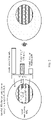
- FIG. 1 shows a communications system to which this application is applicable.
- the communications system includes a network device and a terminal device.
- the network device communicates with the terminal device via a wireless network.
- a wireless communications module of the terminal device may obtain information bits that are to be sent to the network device over a channel.
- the information bits are generated by a processing module of the terminal device, received from another device, or stored in a storage module of the terminal device.
- the terminal device may be referred to as an access terminal, user equipment (user equipment, UE), a subscriber unit, a subscriber station, a mobile station, a mobile console, a remote station, a remote terminal, a mobile device, a user terminal, a terminal, a wireless communications device, a user agent, or a user apparatus.
- the access terminal may be a cellular phone, a handheld device having a wireless communication function, a computing device, another processing device connected to a wireless modem, a vehicle-mounted device, a wearable device, or user equipment in a 5G communications system.
- the network device may be a base transceiver station (base transceiver station, BTS) in a code division multiple access (code division multiple access, CDMA) system, a NodeB (node B, NB) in a wideband code division multiple access (wideband code division multiple access, WCDMA) system, an evolved NodeB (evolved node B, eNB) in a long term evolution (long term evolution, LTE) system, or a gNB (gNB) in a 5G communications system.
- BTS base transceiver station
- CDMA code division multiple access
- NodeB node B
- WCDMA wideband code division multiple access
- eNB evolved NodeB
- LTE long term evolution
- gNB gNB
- the foregoing communications systems to which this application is applicable are merely examples for description, and a communications system to which this application is applicable is not limited thereto.
- the communications system may include another quantity of network devices and another quantity of terminal devices.
- a 5G system is used as an example for description.
- the UE may miss detecting a physical uplink control channel(PDCCH). Consequently, a cognitive error occurs on a quantity of HARQ-ACK bits that need to be fed back, that is, a quantity of HARQ-ACK bits actually fed back by the UE is less than a quantity of HARQ-ACK bits that the gNB schedules the UE to feed back. Further, all UCI sent by the UE on the PUSCH may not be correctly received by the gNB.
- PDCCH physical uplink control channel
- reserved REs for an HARQ-ACK (reserved REs for HARQ-ACK), namely, a reserved RE, is defined for the scenario in which the UE sends the UCI to the gNB on the PUSCH.
- the specific definition is as follows:
- the PUSCH may be divided into two parts in time domain, where the two parts are respectively referred to as a first hop (hop 1) and a second hop (hop 2). Frequency domain resources on the hop 1 and the hop 2 are different.
- the HARQ-ACK, the CSI-partl, and the CSI-part2 are also mapped to the hop 1 and the hop 2 according to a preset rule.
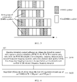
- the foregoing mapping rule may be intuitively represented in FIG. 2 .
- the CSI-partl is mapped only onto a non-reserved RE, and the CSI-part2 has both a part mapped onto reserved REs and a part mapped onto a non-reserved RE.
- the HARQ-ACK is mapped onto reserved REs (in other words, a resource onto which a coded bit of the CSI-part2 has been mapped is punctured).
- a frequency hopping rule for a quantity of PUSCH symbols includes intra-slot (slot) frequency hopping and inter-slot frequency hopping. Details are as follows: For the intra-slot frequency hopping, a quantity of symbols on the hop 1 is rounding half of a total quantity of PUSCH symbols down to a nearest integer, namely, ⁇ N symb PUSCH , s / 2 ⁇ ; and a quantity of symbols on the hop 2 is equal to the total quantity of PUSCH symbols minus the quantity of symbols on the hop 1, namely, N symb PUSCH , s ⁇ ⁇ N symb PUSCH , s / 2 ⁇ .
- N symb PUSCH , s is a total quantity of PUSCH symbols in one slot.
- the hop 1 and the hop 2 are obtained through division by slot in terms of time. For example, a hop with an even slot number is the hop 1, and a hop with an odd slot number is the hop 2.
- a possible case of the intra-slot frequency hopping includes: a quantity of symbols that can carry data on the hop 1 is equal to a quantity of symbols that can carry data on the hop 2; or a quantity of symbols that can carry data on the hop 1 is less than a quantity of symbols that can carry data on the hop 2 by 1; and in the case of the inter-slot frequency hopping, a quantity of symbols that can carry data on the hop 1 is equal to a quantity of symbols that can carry data on the hop 2.
- quantities of coded bits of the parts (the HARQ-ACK, the CSI-partl, and the CSI-part2) of the UCI are also obtained through splitting according to a specific rule during frequency hopping.
- hop PUSCH 1 is a quantity of symbols on the hop 1
- M SC UCI l is a size of a set ⁇ l UCI
- the set ⁇ l UCI is a quantity of REs that can carry data on a symbol l .
- N symb , hop PUSCH 2 is a quantity of symbols on the hop 2.
- a group of consecutive DMRS symbols may include one DMRS symbol, or may include a plurality of consecutive DMRS symbols.
- G CSI ⁇ part 2 1 M 1 ⁇ N L ⁇ Q m ⁇ G CSI ⁇ part 1 1
- G CSI-part 2 2 M 2 ⁇ N L ⁇ Q m ⁇ G CSI-part 1 2
- the CSI-partl is incompletely sent.
- G CSI-part1 cannot be exactly divided by (2 ⁇ N L ⁇ Q m ) . Therefore, the equals sign is invalid in the formula (7), that is: G CSI-part 1 1 ⁇ G CSI-part 1 2
- G CSI-part 1 2 M 2 ⁇ N L ⁇ Q m ⁇ G CSI-part 2 2 > M 2 ⁇ N L ⁇ Q m ⁇ G rvd ACK 2
- the quantity of coded bits of the CSI-part1 on the hop 2 is greater than a quantity of coded bits mapped onto a non-reserved RE, and the CSI-partl cannot be carried by using a reserved RE. Therefore, the CSI-partl is incompletely sent.
- G CSI ⁇ part 2 2 ⁇ G rvd ACK 2 there may be reserved REs on which no data is sent, as shown in FIG. 3 .
- the PUSCH uses a single-carrier discrete Fourier transform spread orthogonal frequency division multiplexing (discrete Fourier transform spread orthogonal frequency division multiplexing, DFT-s-OFDM)
- the foregoing RE on which no data is sent may damage a single-carrier low peak-to-average power ratio (peak-to-average power ratio, PAPR) characteristic for uplink transmission on one or more symbols on the hop 2.
- DFT-s-OFDM discrete Fourier transform spread orthogonal frequency division multiplexing
- PAPR peak-to-average power ratio
- the symbol used in this application is a time unit, and may be an orthogonal frequency-division multiplexing (orthogonal frequency-division multiplexing, OFDM) symbol.
- OFDM orthogonal frequency-division multiplexing
- this application provides a communication method, to resolve a problem that the CSI-part1 is incompletely sent, and further to resolve a problem that a single-carrier characteristic is damaged when a signal is sent on the hop 2 by using the DFT-s-OFDM waveform.
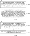
- the communication method includes the following steps.
- the PUSCH is used to carry only UCI
- the PUSCH includes a first frequency hopping resource and a second frequency hopping resource
- a time-domain start symbol of the first frequency hopping resource is before a time-domain start symbol of the second frequency hopping resource.
- the first frequency hopping resource and the second frequency hopping resource are, for example, the hop 1 and the hop 2 described above.
- a frequency domain resource of the first frequency hopping resource is different from a frequency domain resource of the second frequency hopping resource, and the difference means that the frequency domain resource of the first frequency hopping resource partially overlaps or does not overlap the frequency domain resource of the second frequency hopping resource.
- a time-domain end position of the first frequency hopping resource is adjacent to a time-domain start position of the second frequency hopping resource.
- the first frequency hopping resource is consecutive or inconsecutive in time domain
- the second frequency hopping resource is consecutive or inconsecutive in time domain. The explanation of the frequency hopping resource may be applied to another method or implementation in this application.
- the downlink control information described in S410 is, for example, downlink control information (downlink control information, DCI) transmitted on a PDCCH.
- Abase station may indicate, by using different states of one bit in the DCI, whether the PUSCH is used to transmit only the UCI. In other words, whether a current communication scenario is the UCI-only scenario is indicated by using the different states of the bit.
- S420 Send first UCI on the PUSCH, where the first UCI includes at least one of an HARQ-ACK, CSI-partl, and CSI-part2.
- a quantity of coded bits that can be mapped onto reserved REs in the first frequency hopping resource is a first value
- a quantity of coded bits that can be mapped onto reserved REs in the second frequency hopping resource is a second value
- the first value is not less than the second value
- the reserved REs in the first frequency hopping resource and the reserved REs in the second frequency hopping resource are reserved for transmitting potential HARQ-ACK which has less than or equal to 2 bits.
- the “potential HARQ-ACK transmission” is further explained.
- the HARQ-ACK may be transmitted on the PUSCH, or may not be actually transmitted. Regardless of whether the HARQ-ACK is transmitted, these REs are to be reserved.
- to-be-reserved REs correspond to a specific quantity of coded bits to be mapped onto the REs.
- the quantity of HARQ-ACK bits used in the "potential HARQ-ACK transmission" is not greater than 2.
- the quantity of coded bits mapped onto the reserved REs is specifically calculated based on the quantity of HARQ-ACK bits being equal to 2.
- the quantity of coded bits mapped onto the reserved REs may be understood as a quantity of coded bits that are capable of being mapped to the reserved RE, or a corresponding quantity of coded bits corresponding to the reserved RE.
- a reason that information in the CSI-partl is incompletely sent is that a quantity of coded bits that are of the CSI-part1 and that are mapped onto the second frequency hopping resource is relatively small. In other words, a quantity of REs on the second frequency hopping resource that are used to map the CSI-part1 is relatively small, and consequently, the CSI-partl cannot be all mapped onto the second frequency hopping resource.
- this application reduces a quantity of coded bits that are capable of being mapped onto reserved REs in the second frequency hopping resource, thereby increasing a quantity of REs that are in the second frequency hopping resource and that are used to map the CSI-partl. This resolves a problem that due to UCI transmission through frequency hopping in a UCI-only scenario, information in the CSI-partl is incompletely sent.
- a quantity of coded bits that can be mapped onto reserved REs in the first frequency hopping resource is a first value
- a quantity of coded bits that can be mapped onto reserved REs in the second frequency hopping resource is a second value
- the first value is not less than the second value
- the method 400 further includes: determining a first quantity G rvd ACK of coded bits, where G rvd ACK is a sum of the quantities of coded bits that are capable of being mapped onto the reserved REs in the first frequency hopping resource and the second frequency hopping resource, and both the first value and the second value are determined based on G rvd ACK .
- the " sum of the quantities of coded bits mapped onto the reserved REs in the first frequency hopping resource and the second frequency hopping resource” refers to a sum of a quantity of coded bits that are capable of being mapped onto the reserved REs in the first frequency hopping resource and a quantity of coded bits that are capable of being mapped onto the reserved REs in the second frequency hopping resource, but should not be understood as a sum of a quantity of coded bits actually mapped onto the reserved REs in the first frequency hopping resource and a quantity of coded bits actually mapped onto the reserved REs in the second frequency hopping resource.
- the first value is G rvd ACK 1
- G rvd ACK 1 N L ⁇ Q m ⁇ ⁇ G rvd ACK / 2 ⁇ N L ⁇ Q m ⁇
- the second value is G rvd ACK 2
- G rvd ACK 2 N L ⁇ Q m ⁇ ⁇ G rvd ACK / 2 ⁇ N L ⁇ Q m ⁇
- N L is a quantity of transmission layers of the PUSCH
- Q m is a modulation order of the first UCI, namely, a modulation order of the UCI transmitted on the PUSCH.
- G rvd ACK 2 is obtained by performing a rounding down operation on G rvd ACK / 2 ⁇ N L ⁇ Q m , and/or G rvd ACK 2 is obtained by performing a rounding up operation on G rvd ACK / 2 ⁇ N L ⁇ Q m , so that the quantity of coded bits (namely, a quantity of reserved REs) mapped onto the reserved REs in the second frequency hopping resource is less than or equal to the quantity of coded bits (namely, a quantity of reserved REs) mapped onto the reserved REs in the first frequency hopping resource.
- G rvd ACK 1 N L ⁇ Q m ⁇ ⁇ G rvd ACK / 2 ⁇ N L ⁇ Q m ⁇
- G rvd ACK 2 G rvd ACK ⁇ G rvd ACK 1
- G rvd ACK 2 N L ⁇ Q m ⁇ ⁇ G rvd ACK / 2 ⁇ N L ⁇ Q m ⁇
- G rvd ACK 1 G rvd ACK ⁇ G rvd ACK 2 .
- the method 400 further includes: determining a quantity G ACK of coded bits of the HARQ-ACK in the first UCI, where a quantity of coded bits that are of the HARQ-ACK in the first UCI and that are mapped onto the first frequency hopping resource is G ACK (1) , and a value of G ACK (1) is a smaller one of the following two values: a quantity of coded bits mapped onto an RE that is after a first group of consecutive DMRS symbols on the first frequency hopping resource and that are capable of being used to carry data, and a third value that is determined based on G ACK .
- G ACK 1 min N L ⁇ Q m ⁇ ⁇ G ACK / 2 ⁇ N L ⁇ Q m ⁇ , M 3 ⁇ N L ⁇ Q m .
- N L ⁇ Q m ⁇ ⁇ G ACK /(2 ⁇ N L ⁇ Q m ) ⁇ represents the third value
- M 3 ⁇ N L ⁇ Q m represents the quantity of coded bits mapped onto the RE that is after the first group of consecutive DMRS symbols on the first frequency hopping resource and that are capable of being used to carry data
- the DMRS symbol is a symbol used to carry a DMRS.
- M 3 is a quantity of REs that are after the first group of consecutive DMRS symbols on the first frequency hopping resource and that are capable of being used to carry data
- N L is the quantity of transmission layers of the PUSCH
- Q m is the modulation order of the first UCI. There may be one or more symbols in the first group of consecutive DMRS symbols.
- the first group of consecutive DMRS symbols start from the first DMRS symbol on a corresponding resource in time domain, and ends with the last consecutive DMRS symbol.
- FIG. 5 four PUSCH resources, namely, a PUSCH 1, a PUSCH 2, a PUSCH 3, and a PUSCH 4 are shown from top to bottom (the top-to-bottom sequence is used only to logically distinguish between the four PUSCH resources, and imposes no limitation on a frequency-domain position relationship).
- Start symbols of the PUSCH 1 and the PUSCH 3 are DMRS symbols
- start symbols of the PUSCH 2 and the PUSCH 4 are not DMRS symbols.
- the first group of consecutive DMRS symbols in each of the PUSCH 1 and the PUSCH 2 include only one symbol
- the first group of consecutive DMRS symbols in each of the PUSCH 3 and the PUSCH 4 include a plurality of symbols.
- Step 1 A gNB configures parameters such as a scale parameter ⁇ and a code rate compensation parameter ( ⁇ offset HARQ ⁇ ACK , ⁇ offset CSI ⁇ 1 , and ⁇ offset CSI ⁇ 2 ) for the UE by using RRC signaling, where a value of the scale parameter ⁇ is greater than 0 and less than or equal to 1, and one or more groups of values may be configured for the code rate compensation parameter. If one group of values are configured, the group of values are directly used in a subsequent step. If a plurality of groups of values are configured, downlink control information (downlink control information, DCI) in step 2 may be used to indicate indexes of the groups of values.
- DCI downlink control information
- Step 2 The gNB sends DCI to the UE on a PDCCH, where the DCI includes but is not limited to the following information: a PUSCH resource allocated to the UE, whether the PUSCH is UCI-only (or whether the PUSCH includes a UL-SCH), whether frequency hopping is performed for the PUSCH, and parameters such as a modulation and coding scheme index (I MCS ), the quantity N L of transmission layers of the PUSCH, and indexes (optional) of ⁇ offset HARQ ⁇ ACK , ⁇ offset CSI ⁇ 1 and ⁇ offset CSI ⁇ 2 .
- I MCS modulation and coding scheme index
- Step 3 After receiving the DCI, the UE parses the DCI to obtain the PUSCH resource allocated to the UE, whether the PUSCH is UCI-only, whether frequency hopping is performed for the PUSCH, and the parameters such as I MCS and the quantity N L of transmission layers of the PUSCH.
- the UE obtains a code rate R and the modulation order Q m through table lookup by using I MCS .
- the UE obtains, through parsing, values of ⁇ offset HARQ ⁇ ACK , ⁇ offset CSI ⁇ 1 , and ⁇ offset CSI ⁇ 2 based on the indexes, and uses the values in a subsequent step.
- Step 4 If the UE obtains, through parsing, that the PUSCH is UCI-only, and a quantity of HARQ-ACK information bits that need to be sent by the UE is not greater than 2 (that is, the quantity of HARQ-ACK information bits is 0, 1, or 2), the UE calculates, according to the following formula (in the following formula, 2 on the numerator indicates that calculation is performed based on the quantity of HARQ-ACK information bits being 2), a quantity of reserved REs reserved for an HARQ-ACK:
- a quantity G rvd ACK of coded bits mapped onto the reserved REs that may need to be reserved for the HARQ-ACK is calculated based on obtained Q ACK ′ .
- the UE calculates a quantity G ACK of coded bits of the HARQ-ACK, a quantity G CSI-part1 of coded bits of the CSI-part1, and a quantity G CSI-part2 of coded bits of the CSI-part2 based on the parameters such as ⁇ , ⁇ offset HARQ ⁇ ACK , ⁇ offset CSI ⁇ 1 , ⁇ offset CSI ⁇ 2 , R, Q m , and N L .
- Step 5 If the UE needs to perform frequency hopping to parse the PUSCH, the UE calculates a quantity of coded bits of the HARQ-ACK, a quantity of coded bits of the CSI-part1, and a quantity of coded bits of the CSI-part2 respectively on the hop 1 and the hop 2 according to the following formulas:
- G ACK 1 min N L ⁇ Q m ⁇ ⁇ G ACK / 2 ⁇ N L ⁇ Q m ⁇ , M 3 ⁇ N L ⁇ Q m ; or
- G ACK 1 min N L ⁇ Q m ⁇ ⁇ G ACK / 2 ⁇ N L ⁇ Q m ⁇ , M 3 ⁇ N L ⁇ Q m ;
- G ACK 2 G ACK ⁇ G ACK 1 ;
- G CSI-part 1 1 min N L ⁇ Q m ⁇ ⁇ G CSI-part 1 / 2 ⁇ N L ⁇ Q m ⁇ , M 1 ⁇ N L
- Step 6 The UE maps the coded bits of the HARQ-ACK, the CSI-partl, and the CSI-part2 onto the PUSCH based on the parameters calculated in step 5.
- Example 1 Example 2 Example 3 Quantity of transmission layers (Layer number): N L 1 1 1 1 Modulation order (Modulation order): Q m 4 6 4 G rvd ACK 132 162 116 G CSI-part1 348 414 172 G CSI-part2 132 162 116 Hop 1 M 1 60 48 36
- G rvd ACK 1 N L ⁇ Q m ⁇ ⁇ G rvd ACK / 2 ⁇ N L ⁇ Q m ⁇ 64 78 56
- G CSI-part 1 1 min ( N L ⁇ Q m ⁇ ⁇ G CSI-part 1 / 2 ⁇ N L ⁇ Q m ⁇ , 172 204 84 M 1 ⁇ N L ⁇ Q m ⁇ G ACK 1 )
- G CSI-part 2 1 M 1 ⁇ N L ⁇ Q m ⁇ G CSI-part 1 1 68 84 60 Hop 2 M 2 60 48 36
- G rvd ACK 2 N L ⁇
- the quantity of coded bits transmitted on the non-reserved REs on the hop 2 is different from a quantity of coded bits that are of the CSI-part1 and that are mapped onto the non-reserved RE. Therefore, the CSI-part1 cannot be completely carried on the non-reserved REs on the hop 2, and consequently, the CSI-partl is incompletely sent. It can be learned from the last row and the fourth last row in Table 1 that, the quantity G rvd ACK 2 of coded bits mapped onto the reserved REs on the hop 2 is greater than a quantity of coded bits that are of the CSI-part2 and that are mapped onto the hop 2. Therefore, there is no data to be sent on some reserved REs. When the PUSCH uses DFT-s-OFDM, a single-carrier low PAPR characteristic is damaged.
- Table 2 shows a result of calculation by using the communication method provided in this application. It can be learned from the second last row and the third last row in Table 2 that, the quantity of coded bits transmitted on the non-reserved REs on the hop 2 is the same as the quantity of coded bits that are of the CSI-partl and that are mapped onto the non-reserved RE. It can be learned from the last row and the fourth last row in Table 2 that, the quantity G rvd ACK 2 of coded bits mapped onto the reserved REs on the hop 2 is equal to the quantity of coded bits that are of the CSI-part2 and that are mapped onto the hop 2, and there is data to be sent on all reserved REs.
- Example 2 Quantity of transmission layers (Layer number): N L 1 1 1 1 Modulation order (Modulation order): Q m 4 6 4 G rvd ACK 132 162 116 G CSI-part1 348 414 172 G CSI-part2 132 162 116 Hop 1 M 1 60 48 36
- G rvd ACK 1 N L ⁇ Q m ⁇ ⁇ G rvd ACK / 2 ⁇ N L ⁇ Q m ⁇ 68 84 60
- G CSI-part 1 1 min ( N L ⁇ Q m ⁇ ⁇ G CSI-part 1 / 2 ⁇ N L ⁇ Q m ⁇ , 172 204 84 M 1 ⁇ N L ⁇ Q m ⁇ G ACK 1 )
- G CSI ⁇ part 2 1 M 1 ⁇ N L ⁇ Q m ⁇ G ⁇ part 1 1 68 84 60 Hop 2 M 2 60 48 36
- G rvd ACK 2 N
- a problem of the foregoing splitting rule is that a non-reserved REs on the hop 1 is insufficient to carry a quantity of coded bits of the CSI-partl on the hop 1, and consequently, the CSI-partl is incompletely sent.
- the CSI-part1 cannot occupy the reserved REs resource on the hop 1, that is, the CSI-partl should not be greater than an upper limit M 1 ⁇ N L ⁇ Q m ⁇ G rvd ACK 1 (which is referred to as a second upper limit below).
- G ACK is a quantity of coded bits that is calculated based on an actual quantity of HARQ-ACK information bits
- G rvd ACK is a quantity that is of coded bits mapped onto the reserved REs and that is calculated based on the quantity of HARQ-ACK information bits being 2. Therefore, if the actual quantity of HARQ-ACK information bits is 0 or 1, G ACK ⁇ G rvd ACK , and G ACK 1 ⁇ G rvd ACK 1 for the hop 1. In this case, the first upper limit is greater than the second upper limit. Consequently, the non-reserved REs on the hop 1 may be insufficient to carry the quantity G CSI-part1 (1) of coded bits of the CSI-part1 on the hop 1.
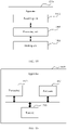
- this application provides another communication method 600.
- the method 600 may be implemented based on the foregoing method, or may be implemented in combination with the foregoing method, or may be independently implemented. As shown in FIG. 6 , the method includes the following steps:
- a quantity G CSI-part1 (1) of coded bits that are of the CSI-partl in the first UCI and that are mapped onto the first frequency hopping resource is a smaller one of a fourth value and a fifth value
- the fourth value is determined based on a quantity G CSI-part1 of coded bits of the CSI-part1 in the first UCI
- the fifth value is determined based on a larger value in G ACK (1) and G rvd ACK 1
- the fifth value is determined based on G ACK (1)
- G ACK (1) is a quantity of coded bits that are of the HARQ-ACK in the first UCI and that are mapped onto the first frequency hopping resource
- G rvd ACK 1 is a quantity of coded bits that can be mapped onto reserved REs in the first frequency hopping resource.
- the fifth value is determined based only on G ACK (1) .
- the fifth value is M 1 ⁇ N L ⁇ Q m - G ACK (1) in the prior art, and this parameter sets an upper limit (namely, a first upper limit) for a resource occupied by the CSI-partl on the first frequency hopping resource.
- the CSI-partl cannot occupy the reserved REs in the first frequency hopping resource. That is, G CSI-part1 (1) should also not be greater than an upper limit M 1 ⁇ N L ⁇ Q m ⁇ G rvd ACK 1 (namely, a second upper limit).
- G ACK (1) is a quantity of coded bits that is calculated based on an actual quantity of HARQ-ACK information bits
- G rvd ACK is a quantity that is of coded bits mapped onto the reserved REs and that is calculated based on the quantity of HARQ-ACK information bits being 2. Therefore, if the actual quantity of HARQ-ACK information bits is 0 or 1, G ACK ⁇ G rvd ACK , and G ACK 1 ⁇ G rvd ACK 1 . That is, on the first frequency hopping resource, G ACK ⁇ G rvd ACK . In this case, the first upper limit is greater than the second upper limit.
- a non-reserved REs in the first frequency hopping resource may be insufficient for carrying the quantity G CSI-part1 (1) of coded bits of the CSI-part1 on the first frequency hopping resource.
- the fifth value is determined based on the larger one of G ACK (1) and G rvd ACK 1 (where when the quantity of HARQ-ACK bits is greater than 2, G rvd ACK 1 is equal to 0), to ensure that G CSI-part1 (1) is calculated by using an actual non-reserved REs in the first frequency hopping resource as a reference, thereby avoiding the foregoing problem that the CSI-part1 is incompletely sent.
- the fifth value is determined based on a larger value in G ACK (1) and G rvd ACK 1 includes that the fifth value is equal to M 1 ⁇ N L ⁇ Q m ⁇ max G ACK 1 , G rvd ACK 1 ; or that the fifth value is determined based on G ACK (1) includes: the fifth value is equal to M 1 ⁇ N L ⁇ Q m - G ACK (1) when the quantity of HARQ-ACK bits is greater than 2; or the fifth value is equal to M 1 ⁇ N L ⁇ Q m ⁇ max G ACK 1 , G rvd ACK 1 when the quantity of HARQ-ACK bits is less than or equal to 2.
- M 1 is a quantity of REs that can carry data and that are in the first frequency hopping resource
- N L is a quantity of transmission layers of the PUSCH
- Q m is a modulation order of the first UCI.
- the fourth value is determined based on a quantity G CSI-part1 of coded bits of the CSI-part1 in the first UCI includes: the fourth value is equal to N L ⁇ Q m ⁇ ⁇ G CSI-part1 /(2 ⁇ N L ⁇ Q m ) ⁇ , where N L is the quantity of transmission layers of the PUSCH, and Q m is the modulation order of the first UCI.
- the method 600 may be separately implemented, or may be jointly implemented with the method 400.
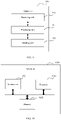
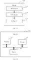
- This application further provides a communication method. As shown in FIG. 7 , the method 700 includes the following steps:
- a reason that information in the CSI-partl is incompletely sent is that a quantity of coded bits that are of the CSI-part1 and that are mapped onto the second frequency hopping resource is relatively small. In other words, a quantity of REs on the second frequency hopping resource that are used to map the CSI-part1 is relatively small, and consequently, the CSI-partl cannot be all mapped onto the second frequency hopping resource.
- this application reduces a quantity of coded bits that are capable of being mapped onto reserved REs in the second frequency hopping resource, thereby increasing a quantity of REs that are in the second frequency hopping resource and that are used to map the CSI-partl. This resolves a problem that due to UCI transmission through frequency hopping in a UCI-only scenario, information in the CSI-partl is incompletely sent.
- the first value is G rvd ACK 1
- G rvd ACK 1 N L ⁇ Q m ⁇ ⁇ G rvd ACK / 2 ⁇ N L ⁇ Q m ⁇ ;
- G rvd ACK 1 N L ⁇ Q m ⁇ ⁇ G rvd ACK / 2 ⁇ N L ⁇ Q m ⁇
- G rvd ACK 2 G rvd ACK ⁇ G rvd ACK 1
- G rvd ACK 2 N L ⁇ Q m ⁇ ⁇ G rvd ACK / 2 ⁇ N L ⁇ Q m ⁇
- G rvd ACK 1 G rvd ACK ⁇ G rvd ACK 2 .
- a quantity of coded bits that are of the HARQ-ACK in the first UCI and that are mapped onto the first frequency hopping resource is G ACK (1)
- a value of G ACK (1) is a smaller one of the following two values: a quantity of coded bits mapped onto an RE that is after a first group of consecutive DMRS symbols on the first frequency hopping resource and that are capable of being used to carry data, and a third value that is determined based on G ACK , where G ACK is a quantity of coded bits of the HARQ-ACK in the first UCI.
- a value of the quantity of coded bits mapped onto the RE that is after the first group of consecutive DMRS symbols on the first frequency hopping resource and that are capable of being used to carry data is equal to M 3 ⁇ N L ⁇ Q m , where M 3 is a quantity of REs that are after the first group of consecutive DMRS symbols on the first frequency hopping resource and that are capable of being used to carry data, N L is the quantity of transmission layers of the PUSCH, Q m is the modulation order of the first UCI, and the third value is N L ⁇ Q m ⁇ G ACK /(2 ⁇ N L ⁇ Q m ) ⁇ .
- the quantity of bits of the HARQ-ACK in the first UCI is not greater than 2.
- G ack (1) min( N L ⁇ Q m ⁇ G ACK /(2 ⁇ N L ⁇ Q m ) ⁇ , M 3 ⁇ N L ⁇ Q m )
- the method 800 includes the following steps:
- a quantity G CSI-part1 (1) of coded bits that are of the CSI-part1 in the first UCI and that are mapped onto the first frequency hopping resource is a smaller one of a fourth value and a fifth value
- the fourth value is determined based on a quantity G CSI-part1 of coded bits of the CSI-part1 in the first UCI
- the fifth value is determined based on a larger value in G ACK (1) and G rvd ACK 1
- the fifth value is determined based on G ACK (1)
- G ACK (1) is a quantity of coded bits that are of the HARQ-ACK in the first UCI and that are mapped onto the first frequency hopping resource
- G rvd ACK 1 is a quantity of coded bits that can be mapped onto reserved REs in the first frequency hopping resource.
- the fifth value is determined based only on G ACK (1) .
- the fifth value is M 1 ⁇ N L ⁇ Q m - G ACK (1) in the prior art, and this parameter sets an upper limit (namely, a first upper limit) for a resource occupied by the CSI-part1 on the first frequency hopping resource.
- the CSI-part1 cannot occupy the reserved REs in the first frequency hopping resource. That is, G CSI-part1 (1) should also not be greater than an upper limit M 1 ⁇ N L ⁇ Q m ⁇ G rvd ACK 1 (namely, a second upper limit).
- G ACK (1) is a quantity of coded bits that is calculated based on an actual quantity of HARQ-ACK information bits
- G rvd ACK is a quantity that is of coded bits mapped onto the reserved REs and that is calculated based on the quantity of HARQ-ACK information bits being 2. Therefore, if the actual quantity of HARQ-ACK information bits is 0 or 1, G ACK ⁇ G rvd ACK , and G ACK 1 ⁇ G rvd ACK 1 . That is, on the first frequency hopping resource, G ACK ⁇ G rvd ACK . In this case, the first upper limit is greater than the second upper limit.
- a non-reserved REs in the first frequency hopping resource may be insufficient for carrying the quantity G CSI-part1 (1) of coded bits of the CSI-part1 on the first frequency hopping resource.
- the fifth value is determined based on the larger one of G ACK (1) and G rvd ACK 1 (where when the quantity of HARQ-ACK bits is greater than 2, G rvd ACK 1 is equal to 0), to ensure that G CSI-part1 (1) is calculated by using an actual non-reserved REs in the first frequency hopping resource as a reference, thereby avoiding the foregoing problem that the CSI-part1 is incompletely sent.
- the fifth value is determined based on a larger value in G ACK (1) and G rvd ACK 1 includes that the fifth value is equal to M 1 ⁇ N L ⁇ Q m ⁇ max G ACK 1 , G rvd ACK 1 ; or that the fifth value is determined based on G ACK (1) includes: the fifth value is equal to M 1 ⁇ N L ⁇ Q m - G ACK (1) when the quantity of HARQ-ACK bits is greater than 2; or the fifth value is equal to M 1 ⁇ N L ⁇ Q m ⁇ max G ACK 1 , G rvd ACK 1 when the quantity of HARQ-ACK bits is less than or equal to 2.
- M 1 is a quantity of REs that can carry data and that are in the first frequency hopping resource
- N L is a quantity of transmission layers of the PUSCH
- Q m is a modulation order of the first UCI.
- the fourth value is determined based on a quantity G CSI-part1 of coded bits of the CSI-part1 in the first UCI includes: the fourth value is equal to N L ⁇ Q m ⁇ G CSI-part1 /(2 ⁇ N L ⁇ Q m ) ⁇ , where N L is the quantity of transmission layers of the PUSCH, and Q m is the modulation order of the first UCI.
- a communication method includes:
- a quantity of coded bits that can be mapped onto reserved resource elements REs in the first frequency hopping resource is a first value
- a quantity of coded bits that can be mapped onto reserved REs in the second frequency hopping resource is a second value
- the first value is not less than the second value
- the reserved REs in the first frequency hopping resource and the reserved REs in the second frequency hopping resource are reserved for transmitting potential HARQ-ACK which a bit quantity is not greater than 2.
- the method may be performed by a terminal device, or may be performed by an apparatus or a chip that is integrated into a terminal device or that is independent from a terminal device.
- this implementation provides an apparatus, where the apparatus includes:
- a quantity of coded bits that can be mapped onto reserved resource elements REs in the first frequency hopping resource is a first value
- a quantity of coded bits that can be mapped onto reserved REs in the second frequency hopping resource is a second value
- the first value is not less than the second value
- the reserved REs in the first frequency hopping resource and the reserved REs in the second frequency hopping resource are reserved for potential HARQ-ACK transmission in which a bit quantity is not greater than 2.
- the communications apparatus may be divided into functional units based on the foregoing method examples.
- each functional unit may be obtained through division based on a corresponding function, or two or more functions may be integrated into one processing unit.
- the integrated unit may be implemented in a form of hardware, or may be implemented in a form of a software functional unit.
- unit division in this application is an example, and is merely logical function division. During actual implementation, another division manner may be used.
- FIG. 9 is a possible schematic structural diagram of a communications apparatus according to this application.
- the apparatus 900 includes a processing unit 901, a receiving unit 902, and a sending unit 903.
- the processing unit 901 is configured to control the apparatus 900 to perform the steps of the communication method shown in FIG. 4 .
- the processing unit 901 may be further configured to perform another process of the technology described in this specification.
- the apparatus 900 may further include a storage unit, configured to store program code and data of the apparatus 900.
- the processing unit 901 is configured to control the receiving unit 902 to receive downlink control information, where the downlink control information is used to schedule a physical uplink shared channel PUSCH, the PUSCH is used to carry only uplink control information UCI, the PUSCH includes a first frequency hopping resource and a second frequency hopping resource, and a time-domain start symbol of the first frequency hopping resource is before a time-domain start symbol of the second frequency hopping resource.
- the processing unit 901 is further configured to control the sending unit 903 to send first UCI on the PUSCH, where the first UCI includes at least one of a hybrid automatic repeat request-acknowledgment HARQ-ACK, a channel state information part 1 CSI-part1, and a channel state information part 2 CSI-part2.
- a quantity of coded bits that can be mapped onto reserved resource elements REs in the first frequency hopping resource is a first value
- a quantity of coded bits that can be mapped onto reserved REs in the second frequency hopping resource is a second value
- the first value is not less than the second value
- the reserved REs in the first frequency hopping resource and the reserved REs in the second frequency hopping resource are reserved for transmitting potential HARQ-ACK which has less than or equal to 2 bits.
- the processing unit 901 may be a processor or a controller, such as a central processing unit (central processing unit, CPU), a general-purpose processor, a digital signal processor (digital signal processor, DSP), an application-specific integrated circuit (application-specific integrated circuit, ASIC), a field programmable gate array (field programmable gate array, FPGA), or another programmable logical device, a transistor logical device, a hardware component, or any combination thereof.
- the processor may implement or execute various example logical blocks, modules, and circuits described with reference to content disclosed in this application.
- the processor may be a combination implementing a computing function, for example, a combination of one or more microprocessors, or a combination of a DSP and a microprocessor.
- the sending unit 903 and the receiving unit 902 are a transceiver
- the storage unit may be a memory.
- the communications apparatus in this application may be an apparatus shown in FIG. 10 .
- the apparatus 1000 includes a processor 1001, a transceiver 1002, and a memory 1003 (optional).
- the processor 1001, the transceiver 1002, and the memory 1003 may communicate with each other by using an internal connection path, to transfer a control signal and/or a data signal.
- a CSI-part1 mapping rule is changed, to resolve a problem that due to UCI transmission through frequency hopping in a UCI-only scenario, information in CSI-part1 is incompletely sent.
- FIG. 11 is a possible schematic structural diagram of another communications apparatus according to this application.
- the apparatus 1100 includes a processing unit 1101, a receiving unit 1102, and a sending unit 1103.
- the processing unit 1101 is configured to control the apparatus 1100 to perform the steps of the communication method shown in FIG. 6 .
- the processing unit 1101 may be further configured to perform another process of the technology described in this specification.
- the apparatus 1100 may further include a storage unit, configured to store program code and data of the apparatus 1100.
- the processing unit 1101 is configured to control the receiving unit 1102 to receive downlink control information, where the downlink control information is used to schedule a PUSCH, the PUSCH is used to carry only UCI, the PUSCH includes a first frequency hopping resource and a second frequency hopping resource, and a time-domain start symbol of the first frequency hopping resource is before a time-domain start symbol of the second frequency hopping resource.
- the processing unit 1101 is further configured to control the sending unit 1103 to send first UCI on the PUSCH, where the first UCI includes at least one of an HARQ-ACK, CSI-part1, and CSI-part2.
- a quantity G CSI-part1 (1)of coded bits that are of the CSI-part1 in the first UCI and that are mapped onto the first frequency hopping resource is a smaller one of a fourth value and a fifth value
- the fourth value is determined based on a quantity G CSI-part1 of coded bits of the CSI-part1 in the first UCI
- the fifth value is determined based on a larger value in G ACK (1) and G rvd ACK 1
- the fifth value is determined based on G ACK (1)
- G ACK (1) is a quantity of coded bits that are of the HARQ-ACK in the first UCI and that are mapped onto the first frequency hopping resource
- G rvd ACK 1 is a quantity of coded bits that can be mapped onto reserved REs in the first frequency hopping resource.
- the processing unit 1101 may be a processor or a controller, for example, may be a CPU, a general-purpose processor, a DSP, an ASIC, an FPGA, or another programmable logic device, a transistor logic device, a hardware component, or any combination thereof.
- the processor may implement or execute various example logical blocks, modules, and circuits described with reference to content disclosed in this application.
- the processor may be a combination implementing a computing function, for example, a combination of one or more microprocessors, or a combination of a DSP and a microprocessor.
- the sending unit 1103 and the receiving unit 1102 are a transceiver
- the storage unit may be a memory.
- the communications apparatus in this application may be an apparatus shown in FIG. 12 .
- the apparatus 1200 includes a processor 1201, a transceiver 1202, and a memory 1203 (optional).
- the processor 1201, the transceiver 1202, and the memory 1203 may communicate with each other by using an internal connection path, to transfer a control signal and/or a data signal.
- a CSI-part1 mapping rule is changed, to resolve a problem that due to UCI transmission through frequency hopping in a UCI-only scenario, information in CSI-part1 is incompletely sent.
- FIG. 13 is a possible schematic structural diagram of a communications apparatus according to this application.
- the apparatus 1300 includes a processing unit 1301, a receiving unit 1302, and a sending unit 1303.
- the processing unit 1301 is configured to control the apparatus 1300 to perform the steps of the communication method shown in FIG. 7 .
- the processing unit 1301 may be further configured to perform another process of the technology described in this specification.
- the apparatus 1300 may further include a storage unit, configured to store program code and data of the apparatus 1300.
- the processing unit 1301 is configured to control the sending unit 1303 to send downlink control information, where the downlink control information is used to schedule a physical uplink shared channel PUSCH, the PUSCH is used to carry only uplink control information UCI, the PUSCH includes a first frequency hopping resource and a second frequency hopping resource, and a time-domain start symbol of the first frequency hopping resource is before a time-domain start symbol of the second frequency hopping resource.
- the processing unit 1301 is further configured to control the receiving unit 1302 to receive first UCI on the PUSCH, where the first UCI includes at least one of a hybrid automatic repeat request-acknowledgment HARQ-ACK, a channel state information part 1 CSI-part1, and a channel state information part 2 CSI-part2.
- a quantity of coded bits that can be mapped onto reserved resource elements REs in the first frequency hopping resource is a first value
- a quantity of coded bits that can be mapped onto reserved REs in the second frequency hopping resource is a second value
- the first value is not less than the second value
- the reserved REs in the first frequency hopping resource and the reserved REs in the second frequency hopping resource are reserved for transmitting potential HARQ-ACK which has less than or equal to 2 bits.
- the processing unit 1301 may be a processor or a controller, such as a central processing unit (central processing unit, CPU), a general-purpose processor, a digital signal processor (digital signal processor, DSP), an application-specific integrated circuit (application-specific integrated circuit, ASIC), a field programmable gate array (field programmable gate array, FPGA), or another programmable logical device, a transistor logical device, a hardware component, or any combination thereof.
- the processor may implement or execute various example logical blocks, modules, and circuits described with reference to content disclosed in this application.
- the processor may be a combination implementing a computing function, for example, a combination of one or more microprocessors, or a combination of a DSP and a microprocessor.
- the sending unit 1303 and the receiving unit 1302 are a transceiver
- the storage unit may be a memory.
- the communications apparatus in this application may be an apparatus shown in FIG. 14 .
- the apparatus 1400 includes a processor 1401, a transceiver 1402, and a memory 1403 (optional).
- the processor 1401, the transceiver 1402, and the memory 1403 may communicate with each other by using an internal connection path, to transfer a control signal and/or a data signal.
- a CSI-part1 mapping rule is changed, to resolve a problem that due to UCI transmission through frequency hopping in a UCI-only scenario, information in CSI-part1 is incompletely sent.
- FIG. 15 is a possible schematic structural diagram of another communications apparatus according to this application.
- the apparatus 1500 includes a processing unit 1501, a receiving unit 1502, and a sending unit 1503.
- the processing unit 1501 is configured to control the apparatus 1500 to perform the steps of the communication method shown in FIG. 8 .
- the processing unit 1501 may be further configured to perform another process of the technology described in this specification.
- the apparatus 1500 may further include a storage unit, configured to store program code and data of the apparatus 1500.
- the processing unit 1501 is configured to control the sending unit 1503 to send downlink control information, where the downlink control information is used to schedule a PUSCH, the PUSCH is used to carry only UCI, the PUSCH includes a first frequency hopping resource and a second frequency hopping resource, and a time-domain start symbol of the first frequency hopping resource is before a time-domain start symbol of the second frequency hopping resource.
- the processing unit 1501 is further configured to control the receiving unit 1502 to receive first UCI on the PUSCH, where the first UCI includes at least one of an HARQ-ACK, CSI-part1, and CSI-part2.
- a quantity G CSI-part1 (1) of coded bits that are of the CSI-part1 in the first UCI and that are mapped onto the first frequency hopping resource is a smaller one of a fourth value and a fifth value
- the fourth value is determined based on a quantity G CSI-part1 of coded bits of the CSI-part1 in the first UCI
- the fifth value is determined based on a larger value in G ACK (1) and G rvd ACK 1
- the fifth value is determined based on G ACK (1)
- G ACK (1) is a quantity of coded bits that are of the HARQ-ACK in the first UCI and that are mapped onto the first frequency hopping resource
- G rvd ACK 1 is a quantity of coded bits that can be mapped onto reserved REs in the first frequency hopping resource.
- the processing unit 1501 may be a processor or a controller, for example, may be a CPU, a general-purpose processor, a DSP, an ASIC, an FPGA, or another programmable logic device, a transistor logic device, a hardware component, or any combination thereof.
- the processor may implement or execute various example logical blocks, modules, and circuits described with reference to content disclosed in this application.
- the processor may be a combination implementing a computing function, for example, a combination of one or more microprocessors, or a combination of a DSP and a microprocessor.
- the sending unit 1502 and the receiving unit 1502 are a transceiver, and the storage unit may be a memory.
- the communications apparatus in this application may be an apparatus shown in FIG. 16 .
- the apparatus 1600 includes a processor 1601, a transceiver 1602, and a memory 1603 (optional).
- the processor 1601, the transceiver 1602, and the memory 1603 may communicate with each other by using an internal connection path, to transfer a control signal and/or a data signal.
- a CSI-part1 mapping rule is changed, to resolve a problem that due to UCI transmission through frequency hopping in a UCI-only scenario, information in CSI-part1 is incompletely sent.
- a communications unit performs an obtaining step in the method embodiments, and all steps other than the obtaining step and the sending step may be performed by the processing unit or the processor.
- a function of a specific unit refer to a corresponding method embodiment. Details are not described herein again.
- sequence numbers of the foregoing processes do not mean execution sequences in various embodiments of this application.
- the execution sequences of the processes should be determined based on functions and internal logic of the processes, and should not be construed as any limitation on the implementation processes of this application.
- the software instruction may include a corresponding software module.
- the software module may be stored in a random access memory (random access memory, RAM), a flash memory, a read-only memory (read only memory, ROM), an erasable programmable read only memory (erasable programmable ROM, EPROM), an electrically erasable programmable read only memory (electrically EPROM, EEPROM), a register, a hard disk, a mobile hard disk, a compact disc read-only memory (CD-ROM), or any other form of storage medium well-known in the art.
- a storage medium is coupled to a processor, so that the processor can read information from the storage medium or write information into the storage medium.
- the storage medium may be a component of the processor.
- the processor and the storage medium may be located in the ASIC.
- All or some of the foregoing embodiments may be implemented by using software, hardware, firmware, or any combination thereof.
- the embodiments may be implemented completely or partially in a form of a computer program product.
- the computer program product includes one or more computer instructions.
- the computer may be a general-purpose computer, a dedicated computer, a computer network, or other programmable apparatuses.
- the computer instructions may be stored in a computer-readable storage medium, or may be transmitted by using the computer-readable storage medium.
- the computer instructions may be transmitted from a website, computer, server, or data center to another website, computer, server, or data center in a wired (for example, a coaxial cable, an optical fiber, or a digital subscriber line (digital subscriber line, DSL)) or wireless (for example, infrared, radio, or microwave) manner.
- the computer-readable storage medium may be any usable medium accessible by a computer, or a data storage device, such as a server or a data center, integrating one or more usable media.
- the usable medium may be a magnetic medium (for example, a floppy disk, a hard disk, or a magnetic tape), an optical medium (for example, a digital versatile disc (digital versatile disc, DVD), a semiconductor medium (for example, a solid-state drive (solid-state drive, SSD)), or the like.
- a magnetic medium for example, a floppy disk, a hard disk, or a magnetic tape
- an optical medium for example, a digital versatile disc (digital versatile disc, DVD)
- a semiconductor medium for example, a solid-state drive (solid-state drive, SSD)
Landscapes
- Engineering & Computer Science (AREA)
- Signal Processing (AREA)
- Computer Networks & Wireless Communication (AREA)
- Quality & Reliability (AREA)
- Mobile Radio Communication Systems (AREA)
- Detection And Prevention Of Errors In Transmission (AREA)
- Communication Control (AREA)
- Financial Or Insurance-Related Operations Such As Payment And Settlement (AREA)
Claims (17)
- Kommunikationsverfahren, umfassend:Empfangen (S610) von Abwärtsstrecken-Steuerinformationen, wobei die Abwärtsstrecken-Steuerinformationen verwendet werden, um einen "Physical Uplink Shared Channel" PUSCH einzuteilen, der PUSCH verwendet wird, um Aufwärtsstrecken-Steuerinformationen UCI ohne "Uplink Shared Channel" UL-SCH zu führen, der PUSCH eine erste Frequenzsprungressource und eine zweite Frequenzsprungressource umfasst und ein Zeitbereichs-Startsymbol der ersten Frequenzsprungressource vor einem Zeitbereichs-Startsymbol der zweiten Frequenzsprungressource kommt; undSenden (S620) von ersten UCI auf dem PUSCH, wobei die ersten UCI einen Kanalzustandsinformationsteil 1 bzw. CSI-Teill umfassen oder die ersten UCI eine "Hybrid Automatic Repeat Request-Acknowledgement" HARQ-ACK und den CSI-Teill umfassen, wobeieine Anzahl G CSI-teil1 (1) codierter Bit, die vom CSI-Teill in den ersten UCI sind und die auf die erste Frequenzsprungressource abgebildet werden, ein kleineres von einem vierten Wert und einem fünften Wert ist und der vierte Wert auf der Basis einer Anzahl G CSI-teil1 codierter Bit des CSI-Teil1 in den ersten UCI bestimmt wird; wobei wenn eine Anzahl von HARQ-ACK-Bit größer als 2 ist, der fünfte Wert gleich M 1· NL·Qm -G ACK(1) ist;wenn eine Anzahl von HARQ-ACK-Bit kleiner oder gleich 2 ist, der fünfte Wert gleich

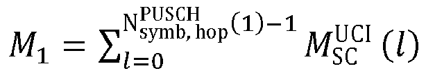


- Verfahren nach Anspruch 1, wobei der vierte Wert gleich NL ·QM ·└G CSI-teil1/(2·NL · Qm)┘ ist.
- Verfahren nach Anspruch 1 oder Anspruch 2, wobei, wenn eine Anzahl von HARQ-ACK-Bit größer als 2 ist

wenn eine Anzahl von HARQ-ACK-Bit kleiner oder gleich 2 ist,
- Verfahren nach einem der Ansprüche 1-3, wobei


- Kommunikationsverfahren, umfassend:Senden (S810) von Abwärtsstrecken-Steuerinformationen, wobei die Abwärtsstrecken-Steuerinformationen verwendet werden, um einen "Physical Uplink Shared Channel" PUSCH einzuteilen, der PUSCH verwendet wird, um Aufwärtsstrecken-Steuerinformationen UCI ohne "Uplink Shared Channel" UL-SCH zu führen, der PUSCH eine erste Frequenzsprungressource und eine zweite Frequenzsprungressource umfasst und ein Zeitbereichs-Startsymbol der ersten Frequenzsprungressource vor einem Zeitbereichs-Startsymbol der zweiten Frequenzsprungressource kommt; undEmpfangen (S820) von ersten UCI auf dem PUSCH, wobei die ersten UCI einen Kanalzustandsinformationsteil 1 bzw. CSI-Teill umfassen oder die ersten UCI eine "Hybrid Automatic Repeat Request-Acknowledgement" HARQ-ACK und den CSI-Teil1 umfassen, wobeieine Anzahl G CSI-teil1(1) codierter Bit, die vom CSI-Teill in den ersten UCI sind und die auf die erste Frequenzsprungressource abgebildet werden, ein kleineres von einem vierten Wert und einem fünften Wert ist und der vierte Wert auf der Basis einer Anzahl G CSI-teil1 codierter Bit des CSI-Teill in den ersten UCI bestimmt wird; wobei wenn eine Anzahl von HARQ-ACK-Bit größer als 2 ist, der fünfte Wert gleich M 1· NL·Qm -G ACK(1) ist;wenn eine Anzahl von HARQ-ACK-Bit kleiner oder gleich 2 ist, der fünfte Wert gleich

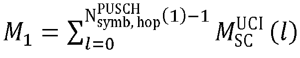


- Verfahren nach Anspruch 5, wobei der vierte Wert gleich NL ·QM ·[G CSI-teil1/(2·NL · Qm)┘ ist.
- Verfahren nach Anspruch 5 oder Anspruch 6, wobei, wenn eine Anzahl von HARQ-ACK-Bit größer als 2 ist

wenn eine Anzahl von HARQ-ACK-Bit kleiner oder gleich 2 ist,
- Verfahren nach einem der Ansprüche 5-7, wobei


- Kommunikationsvorrichtung, die eine Empfangseinheit und eine Sendeeinheit umfasst, wobeiDie Empfangseinheit (1102) ausgelegt ist zum Empfangen von Abwärtsstrecken-Steuerinformationen, wobei die Abwärtsstrecken-Steuerinformationen verwendet werden, um einen "Physical Uplink Shared Channel" PUSCH einzuteilen, der PUSCH verwendet wird, um Aufwärtsstrecken-Steuerinformationen UCI ohne "Uplink Shared Channel" UL-SCH zu führen, der PUSCH eine erste Frequenzsprungressource und eine zweite Frequenzsprungressource umfasst und ein Zeitbereichs-Startsymbol der ersten Frequenzsprungressource vor einem Zeitbereichs-Startsymbol der zweiten Frequenzsprungressource kommt; unddie Sendeeinheit (1103) ausgelegt ist zum Senden von ersten UCI auf dem PUSCH, wobei die ersten UCI einen Kanalzustandsinformationsteil 1 bzw. CSI-Teil1 umfassen oder die ersten UCI eine "Hybrid Automatic Repeat Request-Acknowledgement" HARQ-ACK und den CSI-Teill umfassen, wobeieine Anzahl G CSI-teil1(1) codierter Bit, die vom CSI-Teill in den ersten UCI sind und die auf die erste Frequenzsprungressource abgebildet werden, ein kleineres von einem vierten Wert und einem fünften Wert ist und der vierte Wert auf der Basis einer Anzahl G CSI-teil1 codierter Bit des CSI-Teill in den ersten UCI bestimmt wird; wobei wenn eine Anzahl von HARQ-ACK-Bit größer als 2 ist, der fünfte Wert gleich M 1· NL·Qm -G ACK(1) ist;wenn eine Anzahl von HARQ-ACK-Bit kleiner oder gleich 2 ist, der fünfte Wert gleich


- Vorrichtung nach Anspruch 9, wobei der vierte Wert gleich NL ·QM ·└G CSI-teil1/(2· NL ·Qm)┘ ist.
- Vorrichtung nach Anspruch 9 oder Anspruch 10, wobei, wenn eine Anzahl von HARQ-ACK-Bit größer als 2 ist

wenn eine Anzahl von HARQ-ACK-Bit kleiner oder gleich 2 ist,
- Vorrichtung nach einem der Ansprüche 9-11, wobei


wobei
- Kommunikationsvorrichtung, die eine Sendeeinheit und eine Empfangseinheit umfasst, wobeidie Sendeeinheit (1503) ausgelegt ist zum Senden von Abwärtsstrecken-Steuerinformationen, wobei die Abwärtsstrecken-Steuerinformationen verwendet werden, um einen "Physical Uplink Shared Channel" PUSCH einzuteilen, der PUSCH verwendet wird, um Aufwärtsstrecken-Steuerinformationen UCI ohne "Uplink Shared Channel" UL-SCH zu führen, der PUSCH eine erste Frequenzsprungressource und eine zweite Frequenzsprungressource umfasst und ein Zeitbereichs-Startsymbol der ersten Frequenzsprungressource vor einem Zeitbereichs-Startsymbol der zweiten Frequenzsprungressource kommt; unddie Empfangseinheit (1502) ausgelegt ist zum Empfangen von ersten UCI auf dem PUSCH, wobei die ersten UCI einen Kanalzustandsinformationsteil 1 bzw. CSI-Teill umfassen oder die ersten UCI eine "Hybrid Automatic Repeat Request-Acknowledgement" HARQ-ACK und den CSI-Teill umfassen, wobei eine Anzahl G CSI-teil1(1) codierter Bit, die vom CSI-Teill in den ersten UCI sind und die auf die erste Frequenzsprungressource abgebildet werden, ein kleineres von einem vierten Wert und einem fünften Wert ist und der vierte Wert auf der Basis einer Anzahl G CSI-teil1 codierter Bit des CSI-Teill in den ersten UCI bestimmt wird; wobei wenn eine Anzahl von HARQ-ACK-Bit größer als 2 ist, der fünfte Wert gleich M 1· NL·Qm -G ACK(1) ist;wenn eine Anzahl von HARQ-ACK-Bit kleiner oder gleich 2 ist, der fünfte Wert gleich


- Vorrichtung nach Anspruch 13, wobei der vierte Wert gleich NL·QM ·└G CSI-teil1/(2· NL ·Qm)┘ ist.
- Vorrichtung nach Anspruch 13 oder Anspruch 14, wobei, wenn eine Anzahl von HARQ-ACK-Bit größer als 2 ist

wenn eine Anzahl von HARQ-ACK-Bit kleiner oder gleich 2 ist,
- Vorrichtung nach einem der Ansprüche 13-15, wobei


wobei
- Computerlesbares Speicherungsmedium mit Anweisungen, die, wenn sie durch einen Computer ausgeführt werden, bewirken, dass der Computer das Verfahren nach einem der Ansprüche 1-4 oder einem der Ansprüche 5-8 ausführt.
Applications Claiming Priority (2)
| Application Number | Priority Date | Filing Date | Title |
|---|---|---|---|
| CN201810910306.9A CN110831214B (zh) | 2018-08-10 | 2018-08-10 | 通信方法和装置 |
| PCT/CN2019/099037 WO2020029881A1 (zh) | 2018-08-10 | 2019-08-02 | 通信方法和装置 |
Publications (3)
| Publication Number | Publication Date |
|---|---|
| EP3836710A1 EP3836710A1 (de) | 2021-06-16 |
| EP3836710A4 EP3836710A4 (de) | 2021-11-10 |
| EP3836710B1 true EP3836710B1 (de) | 2022-11-30 |
Family
ID=69413381
Family Applications (1)
| Application Number | Title | Priority Date | Filing Date |
|---|---|---|---|
| EP19848753.0A Active EP3836710B1 (de) | 2018-08-10 | 2019-08-02 | Kommunikationsverfahren und -vorrichtung |
Country Status (9)
| Country | Link |
|---|---|
| US (1) | US11962522B2 (de) |
| EP (1) | EP3836710B1 (de) |
| JP (1) | JP7384334B2 (de) |
| CN (2) | CN110831214B (de) |
| AU (1) | AU2019318583B2 (de) |
| BR (1) | BR112021002359A2 (de) |
| CA (1) | CA3109183C (de) |
| ES (1) | ES2937956T3 (de) |
| WO (1) | WO2020029881A1 (de) |
Families Citing this family (7)
| Publication number | Priority date | Publication date | Assignee | Title |
|---|---|---|---|---|
| US11387933B2 (en) * | 2020-01-31 | 2022-07-12 | Qualcomm Incorporated | Dynamic transmission front end and digital-to-analog converter in modem |
| CN114614953B (zh) * | 2020-12-09 | 2024-11-26 | 维沃移动通信有限公司 | 上行控制信息传输方法、装置、终端及网络侧设备 |
| WO2022151091A1 (zh) * | 2021-01-13 | 2022-07-21 | 华为技术有限公司 | 信息发送方法、信息接收方法及通信装置 |
| WO2023279348A1 (zh) * | 2021-07-08 | 2023-01-12 | 北京小米移动软件有限公司 | 一种跳频方法、装置、用户设备、基站及存储介质 |
| CN115883029B (zh) * | 2021-08-06 | 2025-02-25 | 大唐移动通信设备有限公司 | 一种pucch和pusch复用传输方法、装置及设备 |
| CN116866117A (zh) * | 2023-08-09 | 2023-10-10 | 白盒子(上海)微电子科技有限公司 | 一种基于harq-ack预留资源的信道估计增强方法 |
| WO2025051290A2 (zh) * | 2024-09-25 | 2025-03-13 | 深圳传音控股股份有限公司 | 处理方法、通信设备及计算机可读存储介质 |
Family Cites Families (18)
| Publication number | Priority date | Publication date | Assignee | Title |
|---|---|---|---|---|
| US20120113831A1 (en) | 2010-04-30 | 2012-05-10 | Interdigital Patent Holdings, Inc. | Determination of Carriers and Multiplexing for Uplink Control Information Transmission |
| US8422429B2 (en) | 2010-05-04 | 2013-04-16 | Samsung Electronics Co., Ltd. | Method and system for indicating the transmission mode for uplink control information |
| EP2574126B1 (de) * | 2010-05-21 | 2018-12-05 | Sharp Kabushiki Kaisha | Mobilkommunikationssystem, basisstationsvorrichtung, mobilstationsvorrichtung und kommunikationsverfahren |
| KR101923440B1 (ko) * | 2011-02-15 | 2018-11-29 | 엘지전자 주식회사 | 무선접속시스템에서 채널품질제어정보 전송방법 및 장치 |
| US9294230B2 (en) | 2012-07-02 | 2016-03-22 | Intel Corporation | Multiplexing of channel state information and hybrid automatic repeat request—acknowledgement information |
| EP3697158B1 (de) * | 2014-03-30 | 2021-12-08 | LG Electronics Inc. | Verfahren zum senden/empfangen von downlink-steuerinformationen in einem drahtloskommunikationssystem mit unterstützung von vorrichtung-zu-vorrichtung-kommunikation und einrichtung dafür |
| CN106464455B (zh) * | 2015-03-19 | 2019-11-29 | 华为技术有限公司 | 传输信息的方法、终端设备、网络设备和装置 |
| JP6434043B2 (ja) * | 2015-04-03 | 2018-12-05 | エルジー エレクトロニクス インコーポレイティド | 無線通信システムにおいて信号を送受信する方法及びそのための装置 |
| US10420083B2 (en) * | 2015-07-30 | 2019-09-17 | Intel IP Corporation | OFDMA-based multiplexing of uplink control information |
| WO2017132593A1 (en) * | 2016-01-29 | 2017-08-03 | Ofinno Technologies, Llc | Transmission of sounding reference signals for licensed assisted access |
| WO2017171307A1 (ko) * | 2016-03-31 | 2017-10-05 | 엘지전자 주식회사 | 비주기적 채널 상태 정보-참조 신호를 이용한 채널 상태 보고를 위한 방법 및 이를 위한 장치 |
| WO2018143740A1 (ko) * | 2017-02-05 | 2018-08-09 | 엘지전자 주식회사 | 무선 통신 시스템에서 단말의 상향링크 제어 정보 전송 방법 및 이를 지원하는 장치 |
| CN108112076B (zh) * | 2017-05-05 | 2023-11-21 | 中兴通讯股份有限公司 | 配置上行信号的方法及装置 |
| CN108111263B (zh) * | 2017-06-16 | 2023-02-07 | 中兴通讯股份有限公司 | 确认信息的反馈方法及装置,确认信息的接收方法及装置 |
| US10980008B2 (en) * | 2017-12-08 | 2021-04-13 | Apple Inc. | Determining resources for uplink control information on physical uplink shared channel and physical uplink control channel with frequency hopping |
| US10587386B2 (en) * | 2018-01-12 | 2020-03-10 | Telefonaktiebolaget Lm Ericsson (Publ) | Multiplexing of periodic channel state information on physical uplink shared channel together with hybrid automatic repeat request acknowledgement |
| US10952186B2 (en) * | 2018-01-12 | 2021-03-16 | Apple Inc. | Reserved resource elements for hybrid automatic repeat request bits |
| US11239964B2 (en) * | 2018-05-01 | 2022-02-01 | Marvell Asia Pte, Ltd. | Methods and apparatus for symbol-to-symbol multiplexing of control, data, and reference signals on a 5G uplink |
-
2018
- 2018-08-10 CN CN201810910306.9A patent/CN110831214B/zh active Active
-
2019
- 2019-08-02 CN CN201980053990.6A patent/CN112586071B/zh active Active
- 2019-08-02 CA CA3109183A patent/CA3109183C/en active Active
- 2019-08-02 WO PCT/CN2019/099037 patent/WO2020029881A1/zh not_active Ceased
- 2019-08-02 ES ES19848753T patent/ES2937956T3/es active Active
- 2019-08-02 AU AU2019318583A patent/AU2019318583B2/en active Active
- 2019-08-02 EP EP19848753.0A patent/EP3836710B1/de active Active
- 2019-08-02 JP JP2021506735A patent/JP7384334B2/ja active Active
- 2019-08-02 BR BR112021002359-3A patent/BR112021002359A2/pt unknown
-
2021
- 2021-02-10 US US17/172,396 patent/US11962522B2/en active Active
Non-Patent Citations (1)
| Title |
|---|
| SAMSUNG: "Corrections on UCI Multiplexing in PUSCH", vol. RAN WG1, no. Busan, Korea; 20180521 - 20180525, 11 May 2018 (2018-05-11), XP051461943, Retrieved from the Internet <URL:http://www.3gpp.org/ftp/tsg%5Fran/WG1%5FRL1/TSGR1%5F93/Docs> [retrieved on 20180511] * |
Also Published As
| Publication number | Publication date |
|---|---|
| AU2019318583A1 (en) | 2021-04-01 |
| CA3109183A1 (en) | 2020-02-13 |
| AU2019318583B2 (en) | 2022-06-02 |
| US11962522B2 (en) | 2024-04-16 |
| EP3836710A1 (de) | 2021-06-16 |
| EP3836710A4 (de) | 2021-11-10 |
| CN112586071B (zh) | 2022-09-02 |
| WO2020029881A1 (zh) | 2020-02-13 |
| JP2021534631A (ja) | 2021-12-09 |
| US20210167906A1 (en) | 2021-06-03 |
| JP7384334B2 (ja) | 2023-11-21 |
| CN110831214A (zh) | 2020-02-21 |
| CN112586071A (zh) | 2021-03-30 |
| CN110831214B (zh) | 2023-10-13 |
| ES2937956T3 (es) | 2023-04-03 |
| CA3109183C (en) | 2024-02-27 |
| WO2020029881A9 (zh) | 2020-10-22 |
| BR112021002359A2 (pt) | 2021-05-04 |
Similar Documents
| Publication | Publication Date | Title |
|---|---|---|
| EP3836710B1 (de) | Kommunikationsverfahren und -vorrichtung | |
| US9985764B2 (en) | Terminal device, base station device, communication method, and integrated circuit for processing demodulation reference signals | |
| US8908574B2 (en) | Generation of HARQ-ACK information and power control of HARQ-ACK signals in TDD systems with downlink of carrier aggregation | |
| EP2736293B1 (de) | Ack/nack/sr- ressourcenzuweisungsverfahren und -vorrichtung | |
| CN104170501B (zh) | 终端装置、基站装置以及通信方法 | |
| US10512070B2 (en) | User equipment, network device, and method for determining physical uplink control channel resource | |
| US12167460B2 (en) | Resource indication in random access | |
| EP3609102B1 (de) | Informationsübertragungssteuerungsverfahren, endgerätevorrichtung und netzwerkvorrichtung | |
| EP3589048B1 (de) | Datensendeverfahren und -vorrichtung sowie datenempfangsverfahren und -vorrichtung | |
| JP6306164B2 (ja) | 無線通信システムにおける端末のack/nack送信方法及び装置 | |
| EP3823386B1 (de) | Verfahren und vorrichtung zur verwendung bei der meldung von csi | |
| CN104205971A (zh) | 终端装置、基站装置以及集成电路 | |
| EP3240220B1 (de) | Verfahren zum senden von harq-informationen und datenempfangsseite | |
| EP3057259A1 (de) | Verfahren und vorrichtung zur übertragung von ack/nack über ein endgerät in einem drahtloskommunikationssystem | |
| CN110838904A (zh) | 通信方法和装置 | |
| EP4277186B1 (de) | Kommunikationsverfahren und -vorrichtung sowie computerlesbares speichermedium | |
| RU2786411C2 (ru) | Способ связи и устройство связи |
Legal Events
| Date | Code | Title | Description |
|---|---|---|---|
| STAA | Information on the status of an ep patent application or granted ep patent |
Free format text: STATUS: THE INTERNATIONAL PUBLICATION HAS BEEN MADE |
|
| PUAI | Public reference made under article 153(3) epc to a published international application that has entered the european phase |
Free format text: ORIGINAL CODE: 0009012 |
|
| STAA | Information on the status of an ep patent application or granted ep patent |
Free format text: STATUS: REQUEST FOR EXAMINATION WAS MADE |
|
| 17P | Request for examination filed |
Effective date: 20210310 |
|
| AK | Designated contracting states |
Kind code of ref document: A1 Designated state(s): AL AT BE BG CH CY CZ DE DK EE ES FI FR GB GR HR HU IE IS IT LI LT LU LV MC MK MT NL NO PL PT RO RS SE SI SK SM TR |
|
| A4 | Supplementary search report drawn up and despatched |
Effective date: 20211011 |
|
| RIC1 | Information provided on ipc code assigned before grant |
Ipc: H04W 72/04 20090101ALI20211005BHEP Ipc: H04B 7/06 20060101ALI20211005BHEP Ipc: H04B 7/0413 20170101ALI20211005BHEP Ipc: H04W 72/12 20090101ALI20211005BHEP Ipc: H04L 1/00 20060101ALI20211005BHEP Ipc: H04L 5/00 20060101AFI20211005BHEP |
|
| DAV | Request for validation of the european patent (deleted) | ||
| DAX | Request for extension of the european patent (deleted) | ||
| REG | Reference to a national code |
Ref country code: DE Ref legal event code: R079 Ref document number: 602019022711 Country of ref document: DE Free format text: PREVIOUS MAIN CLASS: H04W0072120000 Ipc: H04L0005000000 |
|
| GRAP | Despatch of communication of intention to grant a patent |
Free format text: ORIGINAL CODE: EPIDOSNIGR1 |
|
| STAA | Information on the status of an ep patent application or granted ep patent |
Free format text: STATUS: GRANT OF PATENT IS INTENDED |
|
| RIC1 | Information provided on ipc code assigned before grant |
Ipc: H04L 1/00 20060101ALI20220524BHEP Ipc: H04W 72/04 20090101ALI20220524BHEP Ipc: H04B 7/06 20060101ALI20220524BHEP Ipc: H04B 7/0413 20170101ALI20220524BHEP Ipc: H04W 72/12 20090101ALI20220524BHEP Ipc: H04L 1/16 20060101ALI20220524BHEP Ipc: H04L 5/00 20060101AFI20220524BHEP |
|
| INTG | Intention to grant announced |
Effective date: 20220622 |
|
| GRAS | Grant fee paid |
Free format text: ORIGINAL CODE: EPIDOSNIGR3 |
|
| GRAA | (expected) grant |
Free format text: ORIGINAL CODE: 0009210 |
|
| STAA | Information on the status of an ep patent application or granted ep patent |
Free format text: STATUS: THE PATENT HAS BEEN GRANTED |
|
| AK | Designated contracting states |
Kind code of ref document: B1 Designated state(s): AL AT BE BG CH CY CZ DE DK EE ES FI FR GB GR HR HU IE IS IT LI LT LU LV MC MK MT NL NO PL PT RO RS SE SI SK SM TR |
|
| REG | Reference to a national code |
Ref country code: CH Ref legal event code: EP Ref country code: GB Ref legal event code: FG4D |
|
| REG | Reference to a national code |
Ref country code: AT Ref legal event code: REF Ref document number: 1535533 Country of ref document: AT Kind code of ref document: T Effective date: 20221215 |
|
| REG | Reference to a national code |
Ref country code: IE Ref legal event code: FG4D |
|
| REG | Reference to a national code |
Ref country code: DE Ref legal event code: R096 Ref document number: 602019022711 Country of ref document: DE |
|
| REG | Reference to a national code |
Ref country code: NL Ref legal event code: FP |
|
| REG | Reference to a national code |
Ref country code: LT Ref legal event code: MG9D |
|
| REG | Reference to a national code |
Ref country code: ES Ref legal event code: FG2A Ref document number: 2937956 Country of ref document: ES Kind code of ref document: T3 Effective date: 20230403 |
|
| PG25 | Lapsed in a contracting state [announced via postgrant information from national office to epo] |
Ref country code: SE Free format text: LAPSE BECAUSE OF FAILURE TO SUBMIT A TRANSLATION OF THE DESCRIPTION OR TO PAY THE FEE WITHIN THE PRESCRIBED TIME-LIMIT Effective date: 20221130 Ref country code: PT Free format text: LAPSE BECAUSE OF FAILURE TO SUBMIT A TRANSLATION OF THE DESCRIPTION OR TO PAY THE FEE WITHIN THE PRESCRIBED TIME-LIMIT Effective date: 20230331 Ref country code: NO Free format text: LAPSE BECAUSE OF FAILURE TO SUBMIT A TRANSLATION OF THE DESCRIPTION OR TO PAY THE FEE WITHIN THE PRESCRIBED TIME-LIMIT Effective date: 20230228 Ref country code: LT Free format text: LAPSE BECAUSE OF FAILURE TO SUBMIT A TRANSLATION OF THE DESCRIPTION OR TO PAY THE FEE WITHIN THE PRESCRIBED TIME-LIMIT Effective date: 20221130 Ref country code: FI Free format text: LAPSE BECAUSE OF FAILURE TO SUBMIT A TRANSLATION OF THE DESCRIPTION OR TO PAY THE FEE WITHIN THE PRESCRIBED TIME-LIMIT Effective date: 20221130 |
|
| REG | Reference to a national code |
Ref country code: AT Ref legal event code: MK05 Ref document number: 1535533 Country of ref document: AT Kind code of ref document: T Effective date: 20221130 |
|
| PG25 | Lapsed in a contracting state [announced via postgrant information from national office to epo] |
Ref country code: RS Free format text: LAPSE BECAUSE OF FAILURE TO SUBMIT A TRANSLATION OF THE DESCRIPTION OR TO PAY THE FEE WITHIN THE PRESCRIBED TIME-LIMIT Effective date: 20221130 Ref country code: PL Free format text: LAPSE BECAUSE OF FAILURE TO SUBMIT A TRANSLATION OF THE DESCRIPTION OR TO PAY THE FEE WITHIN THE PRESCRIBED TIME-LIMIT Effective date: 20221130 Ref country code: LV Free format text: LAPSE BECAUSE OF FAILURE TO SUBMIT A TRANSLATION OF THE DESCRIPTION OR TO PAY THE FEE WITHIN THE PRESCRIBED TIME-LIMIT Effective date: 20221130 Ref country code: IS Free format text: LAPSE BECAUSE OF FAILURE TO SUBMIT A TRANSLATION OF THE DESCRIPTION OR TO PAY THE FEE WITHIN THE PRESCRIBED TIME-LIMIT Effective date: 20230330 Ref country code: HR Free format text: LAPSE BECAUSE OF FAILURE TO SUBMIT A TRANSLATION OF THE DESCRIPTION OR TO PAY THE FEE WITHIN THE PRESCRIBED TIME-LIMIT Effective date: 20221130 Ref country code: GR Free format text: LAPSE BECAUSE OF FAILURE TO SUBMIT A TRANSLATION OF THE DESCRIPTION OR TO PAY THE FEE WITHIN THE PRESCRIBED TIME-LIMIT Effective date: 20230301 |
|
| P01 | Opt-out of the competence of the unified patent court (upc) registered |
Effective date: 20230524 |
|
| PG25 | Lapsed in a contracting state [announced via postgrant information from national office to epo] |
Ref country code: SM Free format text: LAPSE BECAUSE OF FAILURE TO SUBMIT A TRANSLATION OF THE DESCRIPTION OR TO PAY THE FEE WITHIN THE PRESCRIBED TIME-LIMIT Effective date: 20221130 Ref country code: RO Free format text: LAPSE BECAUSE OF FAILURE TO SUBMIT A TRANSLATION OF THE DESCRIPTION OR TO PAY THE FEE WITHIN THE PRESCRIBED TIME-LIMIT Effective date: 20221130 Ref country code: EE Free format text: LAPSE BECAUSE OF FAILURE TO SUBMIT A TRANSLATION OF THE DESCRIPTION OR TO PAY THE FEE WITHIN THE PRESCRIBED TIME-LIMIT Effective date: 20221130 Ref country code: DK Free format text: LAPSE BECAUSE OF FAILURE TO SUBMIT A TRANSLATION OF THE DESCRIPTION OR TO PAY THE FEE WITHIN THE PRESCRIBED TIME-LIMIT Effective date: 20221130 Ref country code: CZ Free format text: LAPSE BECAUSE OF FAILURE TO SUBMIT A TRANSLATION OF THE DESCRIPTION OR TO PAY THE FEE WITHIN THE PRESCRIBED TIME-LIMIT Effective date: 20221130 Ref country code: AT Free format text: LAPSE BECAUSE OF FAILURE TO SUBMIT A TRANSLATION OF THE DESCRIPTION OR TO PAY THE FEE WITHIN THE PRESCRIBED TIME-LIMIT Effective date: 20221130 |
|
| PG25 | Lapsed in a contracting state [announced via postgrant information from national office to epo] |
Ref country code: SK Free format text: LAPSE BECAUSE OF FAILURE TO SUBMIT A TRANSLATION OF THE DESCRIPTION OR TO PAY THE FEE WITHIN THE PRESCRIBED TIME-LIMIT Effective date: 20221130 Ref country code: AL Free format text: LAPSE BECAUSE OF FAILURE TO SUBMIT A TRANSLATION OF THE DESCRIPTION OR TO PAY THE FEE WITHIN THE PRESCRIBED TIME-LIMIT Effective date: 20221130 |
|
| REG | Reference to a national code |
Ref country code: DE Ref legal event code: R097 Ref document number: 602019022711 Country of ref document: DE |
|
| PLBE | No opposition filed within time limit |
Free format text: ORIGINAL CODE: 0009261 |
|
| STAA | Information on the status of an ep patent application or granted ep patent |
Free format text: STATUS: NO OPPOSITION FILED WITHIN TIME LIMIT |
|
| 26N | No opposition filed |
Effective date: 20230831 |
|
| PG25 | Lapsed in a contracting state [announced via postgrant information from national office to epo] |
Ref country code: SI Free format text: LAPSE BECAUSE OF FAILURE TO SUBMIT A TRANSLATION OF THE DESCRIPTION OR TO PAY THE FEE WITHIN THE PRESCRIBED TIME-LIMIT Effective date: 20221130 |
|
| PG25 | Lapsed in a contracting state [announced via postgrant information from national office to epo] |
Ref country code: MC Free format text: LAPSE BECAUSE OF FAILURE TO SUBMIT A TRANSLATION OF THE DESCRIPTION OR TO PAY THE FEE WITHIN THE PRESCRIBED TIME-LIMIT Effective date: 20221130 |
|
| REG | Reference to a national code |
Ref country code: CH Ref legal event code: PL |
|
| PG25 | Lapsed in a contracting state [announced via postgrant information from national office to epo] |
Ref country code: MC Free format text: LAPSE BECAUSE OF FAILURE TO SUBMIT A TRANSLATION OF THE DESCRIPTION OR TO PAY THE FEE WITHIN THE PRESCRIBED TIME-LIMIT Effective date: 20221130 |
|
| PG25 | Lapsed in a contracting state [announced via postgrant information from national office to epo] |
Ref country code: LU Free format text: LAPSE BECAUSE OF NON-PAYMENT OF DUE FEES Effective date: 20230802 |
|
| PG25 | Lapsed in a contracting state [announced via postgrant information from national office to epo] |
Ref country code: LU Free format text: LAPSE BECAUSE OF NON-PAYMENT OF DUE FEES Effective date: 20230802 Ref country code: CH Free format text: LAPSE BECAUSE OF NON-PAYMENT OF DUE FEES Effective date: 20230831 |
|
| REG | Reference to a national code |
Ref country code: BE Ref legal event code: MM Effective date: 20230831 |
|
| REG | Reference to a national code |
Ref country code: IE Ref legal event code: MM4A |
|
| PG25 | Lapsed in a contracting state [announced via postgrant information from national office to epo] |
Ref country code: IT Free format text: LAPSE BECAUSE OF FAILURE TO SUBMIT A TRANSLATION OF THE DESCRIPTION OR TO PAY THE FEE WITHIN THE PRESCRIBED TIME-LIMIT Effective date: 20221130 |
|
| PG25 | Lapsed in a contracting state [announced via postgrant information from national office to epo] |
Ref country code: IE Free format text: LAPSE BECAUSE OF NON-PAYMENT OF DUE FEES Effective date: 20230802 |
|
| PG25 | Lapsed in a contracting state [announced via postgrant information from national office to epo] |
Ref country code: IE Free format text: LAPSE BECAUSE OF NON-PAYMENT OF DUE FEES Effective date: 20230802 |
|
| PG25 | Lapsed in a contracting state [announced via postgrant information from national office to epo] |
Ref country code: BE Free format text: LAPSE BECAUSE OF NON-PAYMENT OF DUE FEES Effective date: 20230831 |
|
| PG25 | Lapsed in a contracting state [announced via postgrant information from national office to epo] |
Ref country code: BG Free format text: LAPSE BECAUSE OF FAILURE TO SUBMIT A TRANSLATION OF THE DESCRIPTION OR TO PAY THE FEE WITHIN THE PRESCRIBED TIME-LIMIT Effective date: 20221130 |
|
| PG25 | Lapsed in a contracting state [announced via postgrant information from national office to epo] |
Ref country code: BG Free format text: LAPSE BECAUSE OF FAILURE TO SUBMIT A TRANSLATION OF THE DESCRIPTION OR TO PAY THE FEE WITHIN THE PRESCRIBED TIME-LIMIT Effective date: 20221130 |
|
| PG25 | Lapsed in a contracting state [announced via postgrant information from national office to epo] |
Ref country code: CY Free format text: LAPSE BECAUSE OF FAILURE TO SUBMIT A TRANSLATION OF THE DESCRIPTION OR TO PAY THE FEE WITHIN THE PRESCRIBED TIME-LIMIT; INVALID AB INITIO Effective date: 20190802 |
|
| PG25 | Lapsed in a contracting state [announced via postgrant information from national office to epo] |
Ref country code: HU Free format text: LAPSE BECAUSE OF FAILURE TO SUBMIT A TRANSLATION OF THE DESCRIPTION OR TO PAY THE FEE WITHIN THE PRESCRIBED TIME-LIMIT; INVALID AB INITIO Effective date: 20190802 |
|
| PGFP | Annual fee paid to national office [announced via postgrant information from national office to epo] |
Ref country code: NL Payment date: 20250704 Year of fee payment: 7 |
|
| PGFP | Annual fee paid to national office [announced via postgrant information from national office to epo] |
Ref country code: ES Payment date: 20250905 Year of fee payment: 7 |
|
| PGFP | Annual fee paid to national office [announced via postgrant information from national office to epo] |
Ref country code: DE Payment date: 20250702 Year of fee payment: 7 |
|
| PGFP | Annual fee paid to national office [announced via postgrant information from national office to epo] |
Ref country code: GB Payment date: 20250703 Year of fee payment: 7 |
|
| PGFP | Annual fee paid to national office [announced via postgrant information from national office to epo] |
Ref country code: FR Payment date: 20250703 Year of fee payment: 7 |
|
| PG25 | Lapsed in a contracting state [announced via postgrant information from national office to epo] |
Ref country code: TR Free format text: LAPSE BECAUSE OF FAILURE TO SUBMIT A TRANSLATION OF THE DESCRIPTION OR TO PAY THE FEE WITHIN THE PRESCRIBED TIME-LIMIT Effective date: 20221130 |