EP3835885A1 - Montre pourvue d'un organe de commande - Google Patents
Montre pourvue d'un organe de commande Download PDFInfo
- Publication number
- EP3835885A1 EP3835885A1 EP19214807.0A EP19214807A EP3835885A1 EP 3835885 A1 EP3835885 A1 EP 3835885A1 EP 19214807 A EP19214807 A EP 19214807A EP 3835885 A1 EP3835885 A1 EP 3835885A1
- Authority
- EP
- European Patent Office
- Prior art keywords
- watch
- control member
- magnetic
- crown
- watch according
- Prior art date
- Legal status (The legal status is an assumption and is not a legal conclusion. Google has not performed a legal analysis and makes no representation as to the accuracy of the status listed.)
- Granted
Links
Images


Classifications
-
- G—PHYSICS
- G04—HOROLOGY
- G04G—ELECTRONIC TIME-PIECES
- G04G21/00—Input or output devices integrated in time-pieces
-
- G—PHYSICS
- G01—MEASURING; TESTING
- G01D—MEASURING NOT SPECIALLY ADAPTED FOR A SPECIFIC VARIABLE; ARRANGEMENTS FOR MEASURING TWO OR MORE VARIABLES NOT COVERED IN A SINGLE OTHER SUBCLASS; TARIFF METERING APPARATUS; MEASURING OR TESTING NOT OTHERWISE PROVIDED FOR
- G01D5/00—Mechanical means for transferring the output of a sensing member; Means for converting the output of a sensing member to another variable where the form or nature of the sensing member does not constrain the means for converting; Transducers not specially adapted for a specific variable
- G01D5/12—Mechanical means for transferring the output of a sensing member; Means for converting the output of a sensing member to another variable where the form or nature of the sensing member does not constrain the means for converting; Transducers not specially adapted for a specific variable using electric or magnetic means
- G01D5/14—Mechanical means for transferring the output of a sensing member; Means for converting the output of a sensing member to another variable where the form or nature of the sensing member does not constrain the means for converting; Transducers not specially adapted for a specific variable using electric or magnetic means influencing the magnitude of a current or voltage
- G01D5/142—Mechanical means for transferring the output of a sensing member; Means for converting the output of a sensing member to another variable where the form or nature of the sensing member does not constrain the means for converting; Transducers not specially adapted for a specific variable using electric or magnetic means influencing the magnitude of a current or voltage using Hall-effect devices
-
- G—PHYSICS
- G01—MEASURING; TESTING
- G01D—MEASURING NOT SPECIALLY ADAPTED FOR A SPECIFIC VARIABLE; ARRANGEMENTS FOR MEASURING TWO OR MORE VARIABLES NOT COVERED IN A SINGLE OTHER SUBCLASS; TARIFF METERING APPARATUS; MEASURING OR TESTING NOT OTHERWISE PROVIDED FOR
- G01D5/00—Mechanical means for transferring the output of a sensing member; Means for converting the output of a sensing member to another variable where the form or nature of the sensing member does not constrain the means for converting; Transducers not specially adapted for a specific variable
- G01D5/12—Mechanical means for transferring the output of a sensing member; Means for converting the output of a sensing member to another variable where the form or nature of the sensing member does not constrain the means for converting; Transducers not specially adapted for a specific variable using electric or magnetic means
- G01D5/14—Mechanical means for transferring the output of a sensing member; Means for converting the output of a sensing member to another variable where the form or nature of the sensing member does not constrain the means for converting; Transducers not specially adapted for a specific variable using electric or magnetic means influencing the magnitude of a current or voltage
- G01D5/142—Mechanical means for transferring the output of a sensing member; Means for converting the output of a sensing member to another variable where the form or nature of the sensing member does not constrain the means for converting; Transducers not specially adapted for a specific variable using electric or magnetic means influencing the magnitude of a current or voltage using Hall-effect devices
- G01D5/145—Mechanical means for transferring the output of a sensing member; Means for converting the output of a sensing member to another variable where the form or nature of the sensing member does not constrain the means for converting; Transducers not specially adapted for a specific variable using electric or magnetic means influencing the magnitude of a current or voltage using Hall-effect devices influenced by the relative movement between the Hall device and magnetic fields
-
- G—PHYSICS
- G04—HOROLOGY
- G04B—MECHANICALLY-DRIVEN CLOCKS OR WATCHES; MECHANICAL PARTS OF CLOCKS OR WATCHES IN GENERAL; TIME PIECES USING THE POSITION OF THE SUN, MOON OR STARS
- G04B3/00—Normal winding of clockworks by hand or mechanically; Winding up several mainsprings or driving weights simultaneously
- G04B3/04—Rigidly-mounted keys, knobs or crowns
-
- G—PHYSICS
- G04—HOROLOGY
- G04C—ELECTROMECHANICAL CLOCKS OR WATCHES
- G04C3/00—Electromechanical clocks or watches independent of other time-pieces and in which the movement is maintained by electric means
- G04C3/001—Electromechanical switches for setting or display
- G04C3/004—Magnetically controlled
-
- G—PHYSICS
- G04—HOROLOGY
- G04C—ELECTROMECHANICAL CLOCKS OR WATCHES
- G04C3/00—Electromechanical clocks or watches independent of other time-pieces and in which the movement is maintained by electric means
- G04C3/001—Electromechanical switches for setting or display
- G04C3/005—Multiple switches
-
- G—PHYSICS
- G04—HOROLOGY
- G04G—ELECTRONIC TIME-PIECES
- G04G21/00—Input or output devices integrated in time-pieces
- G04G21/02—Detectors of external physical values, e.g. temperature
-
- G—PHYSICS
- G04—HOROLOGY
- G04G—ELECTRONIC TIME-PIECES
- G04G21/00—Input or output devices integrated in time-pieces
- G04G21/08—Touch switches specially adapted for time-pieces
-
- G—PHYSICS
- G04—HOROLOGY
- G04R—RADIO-CONTROLLED TIME-PIECES
- G04R60/00—Constructional details
- G04R60/06—Antennas attached to or integrated in clock or watch bodies
-
- G—PHYSICS
- G04—HOROLOGY
- G04R—RADIO-CONTROLLED TIME-PIECES
- G04R60/00—Constructional details
- G04R60/06—Antennas attached to or integrated in clock or watch bodies
- G04R60/10—Antennas attached to or integrated in clock or watch bodies inside cases
-
- G—PHYSICS
- G04—HOROLOGY
- G04G—ELECTRONIC TIME-PIECES
- G04G9/00—Visual time or date indication means
- G04G9/0064—Visual time or date indication means in which functions not related to time can be displayed
Definitions
- the invention relates to a watch provided with at least one function which can be managed electronically and provided with a control member for controlling said function.
- Mechanical or electromechanical watches include as standard a stem-crown which makes it possible to adjust the position of the hands by turning the crown, as well as to wind the barrel in the case of a mechanical watch.
- the crown In most cases, the crown is in a rest position close to the watch case, and it must be pulled to a setting position to adjust the time and, if applicable, the date.
- More and more additional functions are provided, such as electronic display of personal and / or geographic information, for example a diary, fitness and geolocation data. This is also the case for watches equipped with a mechanical movement, for example by adding an electronic module comprising a digital screen arranged on part of the dial.
- the invention aims to produce a watch which does not suffer from the drawbacks described above. This object is achieved by the watch according to the appended claims.
- a watch according to the invention comprises a control member capable of managing a first of the functions of the watch, such as a rotating crown or a chronograph pusher, as well as a magnetic ball which can be manually pivoted by the user around from its center.
- a 3D magnetic sensor is arranged in the watch to detect the orientation of the magnetic field emitted by the magnetic ball, as well as a processor to translate the electrical signal generated by the magnetic sensor into a command that can manage one or more functions of the watch. other than the first feature.
- the magnetic ball is partially arranged in the control member which thus serves as a support for this magnetic ball.
- the watch may further include a proximity detector for detecting the axial position of the control member relative to the caseband of the watch.
- the watch may include a digital screen on which is displayed data, such as the date, the time in digital form, digital messages or other information which is accessible by navigating in one or more menus.
- the watch comprises a stem-crown mechanism for winding and adjusting the hands, as is well known in the state of the art.
- a magnetic ball 15 is partially arranged in the ring 1. The magnetic ball allows the user to manage additional functions, for example controlling a cursor on the screen or selecting an option from a menu displayed on the screen.
- the crown 1 is only one embodiment of a control member mounted laterally with respect to the middle part and to which the invention is applicable.
- a control member is the head (generally non-rotating) of a push-piece of a chronograph watch, the first function of which is the activation of a function of the chronograph.
- the control member to which the invention is applicable is a member which is arranged to adjust at least a first function, of a mechanical or electronic nature, and adapted according to the invention to adjust one or more additional electronic functions. The invention will be described for the case of the rotating crown, which represents the most common case in the watchmaking field but which does not limit the scope of the invention.
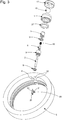
- the figures 1 and 2 represent vertical and horizontal sections of the stem-crown mechanism of a watch according to one embodiment of the invention.
- the different components are displayed in an exploded view.
- the crown 1 is connected to a winding stem 2 by means of a stem connector 6 driven onto one end of the stem 2.
- the assembly of the stem 2 and of the stem connector 6 passes to through a tube 3 fixedly mounted in a hole 4 machined in the wall of the caseband 5 of the watch.
- the rotary crown 1 is connected to the rod connector 6 by a spring push mechanism which is known per se and which does not constitute a limitation on the scope of the invention.
- the crown 1 is fixed on a tubular element 7 which can move axially with respect to the rod connector 6, the latter being housed inside the tubular element 7.
- the rod connector 6 and the element 7 are provided with corresponding profiles which allow the rod 2 to be driven in rotation by the crown 1.
- the thrust of the crown 1 exerted manually by the user of the watch, actuates the axial movement of the element 7 until the latter comes into contact with a vertical wall 8 of the tube 3.
- O-rings 9 made of compressible material between the tube 3 and the middle 5 and between the element 7 and the tube 3 seal the mechanism.
- a spring 10 is mounted between a stop provided on the rod connector 6 and an inner surface of the crown, so that the thrust of the crown compresses the spring 10, which pushes the crown back to its initial position as soon as the pressure exerted on the crown. crown is released.
- the extended position shown in figure 1 is therefore the rest position of the crown. At least when the crown is in this rest position, the functionality of the magnetic ball 15 is ensured.
- the ball 15 is partially incorporated in the crown 1, preferably so that the center of the ball 15 lies on the axis of rotation of the crown. This is achieved by machining a semi-spherical cavity 16 in the outer surface of the crown, sized to receive the ball 15. Then, a cover 17 is fixedly mounted on the crown 1, the cover being provided with 'an opening whose inner surface 18 is also spherical with the same curvature as the cavity 16. In this way, the ball 15 is held in place while leaving part of the ball protruding from the surface of the cover 17. The surfaces of the ball are held in place. the ball 15 and the cavity 16, as well as the inner surface 18 of the cover 17 are configured so that the ball 15 can slide inside the cavity 16 and with respect to the surface 18.
- the ball 15 can therefore be subjected to a pivoting around the three spatial axes X, Y, Z, the center of the ball remaining stationary relative to the crown 1.
- the user can actuate this pivoting by manipulating the part of the ball which comes out of the surface of the cover 17 , preferably used nt a finger to rotate the ball.
- the ball 15 is made of a permanently magnetized material forming a bipolar magnet.
- a bipolar magnet is incorporated into a ball forming a non-magnetic envelope for the magnet.
- the ball therefore comprises two magnetic poles which generate a permanent magnetic field.
- the direction of the field is indicated by arrow 20 at the figures 1 and 2 .
- the manipulation of the ball 15 by the user changes the orientation of the magnetic field with respect to the spatial axes X, Y, Z.
- the watch is equipped with a 3D magnetic sensor 25 which is arranged to detect the magnetic field generated by the ball and determine its orientation.
- the sensor 25 is mounted on a printed circuit board (PCB) 26 installed inside the watch.
- the sensor 25 can be a sensor known per se, such as a Hall effect sensor.
- the intensity of the magnetic field emitted by the ball 15 and the distance provided between the ball 15, when the crown is in its rest position, and the sensor 25 are configured such that at the position of the sensor 25, the earth's magnetic field , which is located between 30 to 60 ⁇ T, i.e. negligible compared to the field generated by the ball 15.
- the ball 15 is operated in the same way as a 'trackball', and makes it possible to translate the changes in the angular position of the ball into commands to activate or select electronic functions.
- a 'trackball' Preferably, only the changes around the Y and Z axes are effectively translated into electrical signals which will form the basis of the commands, for example to navigate in two directions in a menu displayed on a digital screen.
- a processor 27 is on board on the PCB 26 to process the signals generated by the sensor 25 and to translate them into commands which will manage one or more electronic functions of the watch, for example the piloting of a cursor on the screen in two dimensions. It is possible to implement methods and algorithms well known in the field of computer science, for the processing of signals as well as for the generation of commands.
- a battery or other source of electrical energy such as a photovoltaic cell, is present in the watch to power the components mounted on the PCB 26 and / or other electronic components implemented in the watch.
- the figures also show a proximity detector 30 which is configured to detect the axial position of the crown 1.
- this detector comprises a rod 29 in the form of a 'U'.
- Rod 29 is made of a ferromagnetic material, such as ferrite.
- This rod comprises two legs 31 and a connecting portion 32 between the legs. The two legs are inserted into respective blind holes 33 provided in the wall of the middle part 5, from the inside of the wall to the outside, so that the ends of the legs are positioned close to the outer side surface 34 of the case. the wall of the caseband 5.
- the holes 33 could also pass through the wall from side to side.
- the connector portion 32 is provided with a solenoid 35, connected by an electric wire 36 to the PCB 26 on which there are means for measuring a current flowing through this solenoid, when it is subjected to a certain electric voltage, and for communicate the current value to the processor 27.
- the detector 30 is positioned next to the stem-crown mechanism, but at a distance such that the ends of the legs 31 are in front of the inner surface of the crown 1.
- a ring of ferromagnetic material 37 (for example ferrite) is incorporated in the ring 1, so that the lateral surface of this ring 37 is opposite the ends of the legs 31.
- the U-shaped rod 29 forms part of a variable reluctance magnetic circuit, the reluctance being variable in function of the position of ring 37, therefore of crown 1.
- a change in the distance D indicated in figure 5 will change the reluctance of the magnetic circuit, which will be detected based on a change in the current in the solenoid 35.
- This principle is known per se and other embodiments of this type of detector can be used.
- the detector 30 is configured to detect the thrust of the crown, actuated by the user against the force of the spring 10, and to generate an electrical signal as a function of this detection. , so that the processor generates in response a specific command and different from the commands generated by the manipulation of the ball 15.
- the commands generated by the thrust of the crown 1 can be, for example, commands for confirming a selection from among the options. presented in a menu.
- the reversible thrust can also be used to activate and then deactivate the 'trackball' function of the ball 15.
- the duration of the thrust can determine the control; for example, a longer duration for activating or deactivating the 'trackball' function and a shorter duration for confirming a selection as soon as the function is active.
- proximity detector 30 instead of the magnetic detector 30, other types of proximity detector can be used to fulfill the same functions.
- a capacitive detector produced by the integration of two plates of a capacitor arranged respectively in the tube 3 and in the element 7.
- the crown can be moved away from caseband 5, by manually pulling crown 1 from the rest position, to activate mechanical adjustment modes such as adjusting the position of the hands or of the date.
- mechanical adjustment modes such as adjusting the position of the hands or of the date.
- Different systems exist which regulate the axial positioning of the crown 1 and the actuation of the mechanical adjustment, and the invention is applicable in combination with any of these systems.
- any one of these systems can be combined with a push-piece crown as described above.
- the magnetic ball 15 is preferably deactivated, for example by means of the detector 30.
- the ball can remain in operation in this remote position and fulfill the same function or a different function.
- the invention is therefore not limited to mechanical winding watches, but it is also applicable to electronic or electromechanical watches.
- the main characteristic of the invention is that the magnetic ball is partially incorporated in the control member. In this way, the application of several control members to control different functionalities is avoided.
Landscapes
- Physics & Mathematics (AREA)
- General Physics & Mathematics (AREA)
- Electric Clocks (AREA)
- Electromechanical Clocks (AREA)
- Position Input By Displaying (AREA)
Abstract
Description
- L'invention est relative à une montre pourvue d'au moins une fonction gérable de manière électronique et pourvue d'un organe de commande pour contrôler ladite fonction.
- Les montres mécaniques ou électromécaniques comprennent de manière standard une tige-couronne qui permet de régler la position des aiguilles en tournant la couronne, ainsi que de remonter le barillet dans le cas d'une montre mécanique. Dans la plupart des cas, la couronne se trouve dans une position de repos proche de la boîte de la montre, et il faut la tirer vers une position de réglage pour ajuster le temps et, le cas échéant, la date.
- De plus en plus des fonctions additionnelles sont prévues, tel qu'un affichage électronique d'informations personnelles et/ou géographiques, par exemple un agenda, des données fitness et de géolocalisation. Ceci est le cas également pour les montres équipées d'un mouvement mécanique, par exemple par l'ajout d'un module électronique comprenant un écran digital agencé sur une partie du cadran.
- La présence des fonctions additionnelles susmentionnées requiert généralement des moyens de commande spécifiques, qui permettent par exemple de sélectionner une fonction, de naviguer dans un menu, etc.
- Des montres électroniques ont été développées avec un organe de commande de type 'joystick' ou 'trackball'. Des exemples de ces solutions sont respectivement illustrés par les documents
EP 1168113 etEP 0582150 . Mais on notera que ces solutions ne sont pas prévues pour une montre à remontage mécanique. Le documentEP 0582150 décrit également une montre pourvue d'une tige-couronne ainsi que d'un dispositif 'trackball'. Le désavantage de cette dernière solution est que la présence de deux organes de commande séparés spatialement n'est pas toujours souhaitable d'un point de vue esthétique et/ou d'un point de vue économique étant donné que la boîte de montre est plus complexe à usiner. On remarquera aussi qu'une bonne étanchéité de la boîte de montre est plus difficile à obtenir avec les organes de commande de type 'joystick' ou 'trackball' décrits dans les documents antérieurs susmentionnés. - L'invention vise à produire une montre qui ne souffre pas des inconvénients décrits ci-dessus. Ce but est atteint par la montre selon les revendications annexées.
- Une montre selon l'invention comprend un organe de commande apte à gérer une première des fonctionnalités de la montre, telle qu'une couronne rotative ou un poussoir de chronographe, ainsi qu'une boule magnétique qui peut être pivotée manuellement par l'utilisateur autour de son centre. Un capteur magnétique 3D est agencé dans la montre pour détecter l'orientation du champ magnétique émis par la boule magnétique, ainsi qu'un processeur pour traduire le signal électrique généré par le capteur magnétique en une commande pouvant gérer une ou plusieurs fonctionnalités de la montre autre que la première fonctionnalité. De manière caractéristique pour l'invention, la boule magnétique est agencée partiellement dans l'organe de commande qui sert ainsi de support à cette boule magnétique. Ainsi, aucun usinage particulier n'est nécessaire dans la carrure ou autre partie formant la boîte de montre, seul l'organe de commande qui est fabriqué séparément de la boîte de montre devant être configuré pour recevoir la boule magnétique. De plus, comme l'organe de commande fait saillie hors de la carrure, l'accès à la boule magnétique par un utilisateur pour l'actionner est facilité car cette boule magnétique est située à une certaine distance de la surface extérieure de la carrure. La montre peut comprendre en outre un détecteur de proximité pour détecter la position axiale de l'organe de commande par rapport à la carrure de la montre.
- L'invention sera décrite ci-après de manière plus détaillée à l'aide des dessins annexés, donnés à titre d'exemples nullement limitatifs, dans lesquels :
- La
figure 1 représente une section verticale du mécanisme tige-couronne en position 'tirée', dans une montre selon une forme d'exécution de l'invention. - La
figure 2 représente une section horizontale du même mécanisme que lafigure 1 , mais maintenant en position 'poussée'. - La
figure 3 représente une vue éclatée des composants du mécanisme desfigures 1 et 2 . - Les
figures 4 et 5 sont des sections qui représentent la position d'un détecteur magnétique incorporée dans la montre desfigures 1 à 2 , pour détecter la position de la couronne par rapport à la carrure de la montre. - L'invention est décrite pour le cas d'une montre à aiguilles et à remontage mécanique, pourvue de fonctions additionnelles de caractère électroniques. Par exemple, la montre peut comprendre un écran digital sur lequel s'affichent des données, telles que la date, le temps sous forme numérique, des messages numériques ou d'autres informations qui sont accessibles en navigant dans un ou plusieurs menus. La montre comprend un mécanisme tige-couronne de remontage et de réglage des aiguilles, tel qu'il est bien connu dans l'état de la technique. De manière caractéristique pour l'invention, et avec référence aux figures, une boule magnétique 15 est agencée partiellement dans la couronne 1. La boule magnétique permet à l'utilisateur de gérer des fonctions additionnelles, par exemple le pilotage d'un curseur sur l'écran ou la sélection d'une option dans un menu affiché sur l'écran.
- La couronne 1 n'est qu'une forme d'exécution d'un organe de commande monté latéralement par rapport à la carrure et auquel l'invention est applicable. Un autre exemple d'un tel organe de commande est la tête (généralement non-rotative) d'un poussoir d'une montre chronographe dont la première fonction est l'activation d'une fonction du chronographe. De manière générale, l'organe de commande auquel l'invention est applicable est un organe qui est agencé pour régler au moins une première fonction, de caractère mécanique ou électronique, et adapté selon l'invention pour régler une ou plusieurs fonctions électroniques additionnelles. L'invention sera décrite pour le cas de la couronne rotative, qui représente le cas le plus courant dans le domaine horloger mais qui ne limite pas la portée de l'invention.
- Les
figures 1 et 2 représentent des coupes verticales et horizontales du mécanisme tige-couronne d'une montre selon une forme d'exécution de l'invention. A lafigure 3 , les différents composants sont visualisés dans une vue éclatée. De manière connue, la couronne 1 est reliée à une tige de remontoir 2 par l'intermédiaire d'un raccord-tige 6 chassé sur une extrémité de la tige 2. L'ensemble de la tige 2 et du raccord-tige 6 passe à travers un tube 3 monté de manière fixe dans un trou 4 usiné dans la paroi de la carrure 5 de la montre. - Dans la forme d'exécution représentée aux figures, la couronne rotative 1 est reliée au raccord-tige 6 par un mécanisme de poussoir à ressort qui est connu en soi et qui ne forme pas une limitation de la portée de l'invention. La couronne 1 est fixée sur un élément tubulaire 7 qui peut se déplacer axialement par rapport au raccord-tige 6, celui-ci étant logé à l'intérieur de l'élément tubulaire 7. Le raccord-tige 6 et l'élément 7 sont pourvus de profils correspondants qui permettent l'entrainement de la tige 2 en rotation par la couronne 1. Comme montré à la
figure 2 , la poussée de la couronne 1, exercée manuellement par l'utilisateur de la montre, actionne le mouvement axial de l'élément 7 jusqu'à ce que ce dernier arrive en contact avec une paroi verticale 8 du tube 3. Des bagues toriques 9 en matériau compressible entre le tube 3 et la carrure 5 et entre le l'élément 7 et le tube 3 assurent l'étanchéité du mécanisme. Un ressort 10 est monté entre une butée pourvue sur le raccord tige 6 et une surface intérieure de la couronne, de sorte que la poussée de la couronne comprime le ressort 10, qui repousse la couronne vers sa position initiale dès que la pression exercée sur la couronne est relâchée. La position étendue représentée à lafigure 1 est donc la position de repos de la couronne. Au moins quand la couronne se trouve dans cette position de repos, la fonctionnalité de la boule magnétique 15 est assurée. - La boule 15 est incorporée partiellement dans la couronne 1, de préférence de sorte que le centre de la boule 15 se trouve sur l'axe de rotation de la couronne. Ceci est réalisé par l'usinage d'une cavité 16 semi-sphérique dans la surface extérieure de la couronne, dimensionnée pour recevoir la boule 15. Ensuite, un couvercle 17 est monté de manière fixe sur la couronne 1, le couvercle étant pourvu d'une ouverture dont la surface intérieure 18 est également sphérique avec la même courbure que la cavité 16. De cette manière, la boule 15 est maintenue en place toute en laissant une partie de la boule sortir de la surface du couvercle 17. Les surfaces de la boule 15 et de la cavité 16, ainsi que la surface intérieure 18 du couvercle 17 sont configurées pour que la boule 15 puisse glisser à l'intérieur de la cavité 16 et par rapport à la surface 18. La boule 15 peut donc subir un pivotement autour des trois axes spatiales X, Y, Z, le centre de la boule restant immobile par rapport à la couronne 1. L'utilisateur peut actionner ce pivotement par la manipulation de la partie de la boule qui sort de la surface du couvercle 17, de préférence en utilisant un doigt pour faire pivoter la boule.
- La boule 15 est fabriquée d'un matériau magnétisé en permanence formant un aimant bipolaire. Dans une variante, un aimant bipolaire est incorporé dans une boule formant une enveloppe non magnétique pour l'aimant. La boule comprend donc deux pôles magnétiques qui génèrent un champ magnétique permanent. La direction du champ est indiquée par la flèche 20 aux
figures 1 et 2 . - La manipulation de la boule 15 par l'utilisateur change l'orientation du champ magnétique par rapport aux axes spatiaux X, Y, Z. La montre est équipée d'un capteur magnétique 3D 25 qui est agencé pour détecter le champ magnétique généré par la boule et déterminer son orientation. Le capteur 25 est monté sur une carte de circuit imprimé (PCB) 26 installée à l'intérieur de la montre. Le capteur 25 peut être un capteur connu en soi tel qu'un capteur à effet Hall. L'intensité du champ magnétique émis par la boule 15 et la distance prévue entre la boule 15, lorsque la couronne est dans sa position de repos, et le capteur 25 sont configurés tels qu'à la position du capteur 25, le champ magnétique terrestre, qui est situé entre 30 à 60 µT, soit négligeable par rapport au champ généré par la boule 15.
- La boule 15 est opérée de la même manière qu'un 'trackball', et permet de traduire les changements de la position angulaire de la boule en commandes pour activer ou sélectionner des fonctions électroniques. De préférence, seulement les changements autour des axes Y et Z sont effectivement traduits en signaux électriques qui vont former la base des commandes, par exemple pour naviguer en deux directions dans un menu affiché sur un écran digital.
- Un processeur 27 est à bord sur le PCB 26 pour traiter les signaux générés par le capteur 25 et pour les traduire en commandes qui vont gérer une ou plusieurs fonctionnalités électroniques de la montre, par exemple le pilotage d'un curseur sur l'écran en deux dimensions. On peut implémenter des méthodes et des algorithmes bien connus du domaine de l'informatique, pour le traitement des signaux ainsi que pour la génération des commandes. Une batterie ou autre source d'énergie électrique, telle qu'une cellule photovoltaïque, est présente dans la montre pour alimenter les composants montés sur le PCB 26 et/ou d'autres composants électroniques implémentés dans la montre.
- Aux figures on voit également un détecteur de proximité 30 qui est configuré pour détecter la position axiale de la couronne 1. Dans la forme d'exécution représentée aux figures et illustrée en détail aux
figures 4 et 5 , ce détecteur comprend une tige 29 en forme de 'U'. La tige 29 est fabriquée d'un matériau ferromagnétique, tel que la ferrite. Cette tige comprend deux jambes 31 et une portion de raccord 32 entre les jambes. Les deux jambes sont insérées dans des trous borgnes respectifs 33 pourvus dans la paroi de la carrure 5, de l'intérieur de la paroi vers l'extérieur, de sorte que les extrémités des jambes soient positionnées à proximité de la surface latérale extérieure 34 de la paroi de la carrure 5. Les trous 33 pourraient également traverser la paroi d'un côté à l'autre. La portion de raccord 32 est pourvue d'un solénoïde 35, connecté par un fil électrique 36 au PCB 26 sur lequel se trouvent des moyens pour mesurer un courant passant par ce solénoïde, lorsqu'il est soumis à une certaine tension électrique, et pour communiquer la valeur du courant au processeur 27. - Comme on voit à la
figure 4 , le détecteur 30 est positionné à côté du mécanisme tige-couronne, mais à une distance telle que les extrémités des jambes 31 se trouvent en face de la surface intérieure de la couronne 1. Un anneau en matériau ferromagnétique 37 (par exemple ferrite) est incorporé dans la couronne 1, de sorte que la surface latérale de cet anneau 37 se trouve en face des extrémités des jambes 31. La tige 29 en forme de U forme une partie d'un circuit magnétique à réluctance variable, la réluctance étant variable en fonction de la position de l'anneau 37, donc de la couronne 1. Un changement de la distance D indiquée à lafigure 5 va changer la réluctance du circuit magnétique, ce qui sera détecté sur base d'un changement du courant dans le solénoïde 35. Ce principe est connu en soi et d'autres modes de réalisation de ce type de détecteur peuvent être utilisés. - Dans la forme d'exécution représentée aux figures, le détecteur 30 est configuré pour détecter la poussée de la couronne, actionnée par l'utilisateur à l'encontre de la force du ressort 10, et de générer un signal électrique en fonction de cette détection, de sorte que le processeur génère en réponse une commande spécifique et différente des commandes générées par la manipulation de la boule 15. Les commandes générées par la poussée de la couronne 1 peuvent être par exemple des commandes de confirmation d'une sélection parmi des options présentées dans un menu. La poussée réversible peut être utilisée également pour activer et ensuite désactiver la fonction 'trackball' de la boule 15. Dans une variante, a durée de la poussée peut déterminer la commande ; par exemple, une durée plus longue pour l'activation ou désactivation de la fonction 'trackball' et une durée plus courte pour confirmer une sélection dès que la fonction est active.
- Au lieu du détecteur magnétique 30, d'autres types de détecteur de proximité peuvent être utilisés pour remplir les mêmes fonctionnalités. Par exemple, on peut prévoir un détecteur capacitif réalisé par l'intégration de deux plaques d'un condensateur agencées respectivement dans le tube 3 et dans l'élément 7.
- Dans beaucoup de montres mécaniques ou électroniques, la couronne peut être éloignée de la carrure 5, en tirant manuellement la couronne 1 par rapport à la position de repos, pour activer des modes de réglage mécanique tel que l'ajustement de la position des aiguilles ou du quantième. Différents systèmes existent qui règlent le positionnement axial de la couronne 1 et l'actionnement du réglage mécanique, et l'invention est applicable en combinaison avec l'un quelconque de ces systèmes. De plus, dans une montre selon l'invention, l'un quelconque de ces systèmes peut être combiné avec une couronne à poussoir telle que décrit ci-dessus. Quand la couronne est éloignée de la carrure en position de réglage, la boule magnétique 15 est de préférence désactivée, par exemple par l'intermédiaire du détecteur 30. Cependant, de manière alternative, la boule peut rester en opération dans cette position éloignée et remplir une même fonction ou une fonction différente.
- L'invention n'est donc pas limitée aux montres à remontage mécanique, mais elle est applicable également à des montres électroniques ou électromécaniques. La caractéristique principale de l'invention est que la boule magnétique est incorporée partiellement dans l'organe de commande. De cette manière, on évite l'application de plusieurs organes de commande pour commander différentes fonctionnalités.
Claims (13)
- Une montre comprenant une boîte de montre qui inclut une carrure (5), un mouvement horloger à l'intérieur de la carrure et un organe de commande (1) monté latéralement par rapport à la carrure, l'organe de commande étant configuré pour remplir au moins une première fonction de la montre, la montre étant pourvue d'une ou plusieurs fonctions additionnelles gérables par des signaux électriques, caractérisée en ce que la montre comprend en outre :- une boule magnétique (15) incorporée partiellement dans l'organe de commande (1) de manière que cette boule magnétique puisse pivoter autour de son centre dans les trois dimensions spatiales, le centre restant immobile par rapport à l'organe de commande (1), et que la boule magnétique (15) soit accessible à un utilisateur de la montre de sorte que l'utilisateur puisse pivoter manuellement cette boule magnétique ;- un capteur magnétique (25) agencé fixe relativement à la boîte de montre, ce capteur magnétique étant apte à détecter l'orientation d'un champ magnétique généré par la boule magnétique et à fournir un signal électrique qui est représentatif de ladite orientation ; et- un processeur (27) configuré pour gérer ladite une ou plusieurs fonctions additionnelles sur base du signal électrique généré par le capteur magnétique (25).
- Une montre selon la revendication 1, caractérisée en ce que l'organe de commande (1) est déplaçable entre une première position proche de la carrure (5) et au moins une deuxième position plus éloignée de la carrure.
- Une montre selon la revendication 2, caractérisée en ce qu'elle comprend en outre un détecteur de proximité (30) configuré pour détecter la position axiale de l'organe de commande (1) par rapport à la carrure (5).
- Une montre selon la revendication 3, caractérisée en ce que ledit détecteur (30) est un détecteur magnétique à réluctance variable.
- Une montre selon la revendication 5, caractérisée en ce que le détecteur de proximité (30) comprend une tige (29) en forme de 'U' et fabriquée d'un matériau ferromagnétique, la tige comprenant deux jambes (31) et une portion de raccord (32) et étant pourvue d'un solénoïde (35), les deux jambes étant agencées dans la paroi latérale de la carrure de sorte que les extrémités libres de ces jambes (31) se trouvent à proximité de la surface latérale extérieure (34) de la carrure (5) et en face d'un matériau ferromagnétique (37) formant au moins en partie l'organe de commande (1), le solénoïde (35) étant relié à un moyen de détection de l'intensité d'un courant le traversant lorsqu'une certaine tension lui est appliquée.
- Une montre selon l'une quelconque des revendications 3 à 5, caractérisée en ce que :- l'organe de commande (1) est capable de subir un rapprochement axial et auto-réversible par rapport à la carrure (5), à partir de ladite position de repos ;- le détecteur de proximité (30) est agencé de manière à pouvoir détecter ledit rapprochement ; et- le processeur (27) est configuré pour engendrer en réponse de la détection du rapprochement une commande qui est différente des commandes générées par la manipulation de la boule magnétique (15).
- Une montre selon la revendication 6, caractérisée en ce que l'organe de commande (1) est lié à un mécanisme de poussoir à ressort (10).
- Une montre selon la revendication 6 ou 7, caractérisée en ce qu'une commande générée par la détection du rapprochement axial est l'activation ou la désactivation de la fonction de la boule magnétique (15).
- Une montre selon la revendication 6 ou 7, caractérisée en ce qu'une commande générée par la détection du rapprochement axial est la confirmation d'une sélection.
- Une montre selon l'une quelconque des revendications précédentes, caractérisée en ce que l'organe de commande est une couronne rotative (1), la rotation de la couronne autour de son axe de rotation effectuant au moins ladite première fonction.
- Une montre selon la revendication 10, caractérisée en ce que la couronne (1) est reliée à une tige de réglage (2) d'une ou plusieurs fonctions du mouvement horloger.
- Une montre selon l'une quelconque des revendications précédentes, caractérisée en ce que le mouvement horloger est du type mécanique.
- Une montre selon l'une quelconque des revendications précédentes, caractérisée en ce que le capteur magnétique (25) est monté sur une carte de circuit imprimé (26) installée à l'intérieur de la boîte de montre.
Priority Applications (4)
| Application Number | Priority Date | Filing Date | Title |
|---|---|---|---|
| EP19214807.0A EP3835885B1 (fr) | 2019-12-10 | 2019-12-10 | Montre pourvue d'un organe de commande |
| US17/064,830 US11599066B2 (en) | 2019-12-10 | 2020-10-07 | Watch provided with a control member |
| JP2020186962A JP7041229B2 (ja) | 2019-12-10 | 2020-11-10 | 制御部材を備える小型時計 |
| CN202011426869.4A CN113050406A (zh) | 2019-12-10 | 2020-12-09 | 设置有控制部件的表 |
Applications Claiming Priority (1)
| Application Number | Priority Date | Filing Date | Title |
|---|---|---|---|
| EP19214807.0A EP3835885B1 (fr) | 2019-12-10 | 2019-12-10 | Montre pourvue d'un organe de commande |
Publications (2)
| Publication Number | Publication Date |
|---|---|
| EP3835885A1 true EP3835885A1 (fr) | 2021-06-16 |
| EP3835885B1 EP3835885B1 (fr) | 2023-12-06 |
Family
ID=68848037
Family Applications (1)
| Application Number | Title | Priority Date | Filing Date |
|---|---|---|---|
| EP19214807.0A Active EP3835885B1 (fr) | 2019-12-10 | 2019-12-10 | Montre pourvue d'un organe de commande |
Country Status (4)
| Country | Link |
|---|---|
| US (1) | US11599066B2 (fr) |
| EP (1) | EP3835885B1 (fr) |
| JP (1) | JP7041229B2 (fr) |
| CN (1) | CN113050406A (fr) |
Families Citing this family (3)
| Publication number | Priority date | Publication date | Assignee | Title |
|---|---|---|---|---|
| KR101986369B1 (ko) * | 2018-03-02 | 2019-06-05 | 양윤태 | 배관 청소기 |
| EP4231100B1 (fr) * | 2022-02-22 | 2024-09-18 | ETA SA Manufacture Horlogère Suisse | Dispositif de commande horloger |
| US20240319677A1 (en) * | 2023-03-24 | 2024-09-26 | Apple Inc. | Crown sensing system for an electronic watch |
Citations (4)
| Publication number | Priority date | Publication date | Assignee | Title |
|---|---|---|---|---|
| EP0582150A1 (fr) | 1992-08-03 | 1994-02-09 | Eta SA Fabriques d'Ebauches | Dispositif de commande à bille d'une pièce d'horlogerie apte à recevoir des messages radiodiffusés |
| US5969520A (en) * | 1997-10-16 | 1999-10-19 | Sauer Inc. | Magnetic ball joystick |
| EP1168113A1 (fr) | 2000-06-20 | 2002-01-02 | The Swatch Group Management Services AG | Dispositif de commutation électrique entre au moins trois contacts différents |
| US20190170834A1 (en) * | 2016-08-11 | 2019-06-06 | Huawei Technologies Co., Ltd. | Information processing method and mobile device |
Family Cites Families (28)
| Publication number | Priority date | Publication date | Assignee | Title |
|---|---|---|---|---|
| EP0660258B1 (fr) * | 1993-12-20 | 2000-03-08 | Seiko Epson Corporation | Dispositif de pointage électronique |
| CH690513A5 (de) * | 1995-04-19 | 2000-09-29 | Asulab Sa | Universaluhr mit drehbarem Aussenring. |
| FR2763710B1 (fr) * | 1997-05-26 | 1999-08-27 | Jdc Electronic Sa | Dispositif de commande de fonctions d'un instrument horaire et procede pour la mise en oeuvre de ce dispositif |
| US6501458B2 (en) * | 1999-06-30 | 2002-12-31 | Caterpillar Inc | Magnetically coupled input device |
| US6597378B1 (en) * | 2000-01-18 | 2003-07-22 | Seiko Epson Corporation | Display device, portable information processing apparatus, information storage medium, and electronic apparatus |
| EP1176480A1 (fr) * | 2000-07-27 | 2002-01-30 | Asulab S.A. | Dispositif d'introduction de données dans un objet portable |
| ATE496319T1 (de) | 2006-11-09 | 2011-02-15 | Swatch Group Res & Dev Ltd | Magnetische vorrichtung zur betätigung einer uhr |
| HK1095988A2 (en) * | 2007-01-31 | 2007-05-18 | National Electronics & Watch Co. Ltd. | A timepiece apparatus |
| US9870021B2 (en) * | 2009-04-15 | 2018-01-16 | SeeScan, Inc. | Magnetic manual user interface devices |
| JP4962803B2 (ja) * | 2009-06-09 | 2012-06-27 | カシオ計算機株式会社 | 回転スイッチ |
| JP2012043005A (ja) * | 2010-08-12 | 2012-03-01 | Alps Electric Co Ltd | 操作感触付与型トラックボール装置 |
| US9569002B2 (en) * | 2010-12-17 | 2017-02-14 | Blackberry Limited | Portable electronic device having a sensor arrangement for gesture recognition |
| JP2013206304A (ja) * | 2012-03-29 | 2013-10-07 | Nissan Motor Co Ltd | トラックボール装置及びステアリングスイッチ |
| JP6171016B2 (ja) | 2012-09-14 | 2017-07-26 | ワイドヴァンテージ インク | 磁場センサを用いて使用者入力を判断する電気装置 |
| EP2789254A1 (fr) | 2013-04-12 | 2014-10-15 | Montres Jaquet Droz SA | Bracelet ergonomique pour montre ou bijou |
| US10048718B2 (en) * | 2014-06-25 | 2018-08-14 | Allegro Microsystems, Llc | Joystick assembly |
| CN204116821U (zh) | 2014-09-25 | 2015-01-21 | 李红 | 一种翻盖智能手表 |
| EP3015925B1 (fr) | 2014-10-28 | 2020-07-15 | The Swatch Group Research and Development Ltd. | Détection optique de la position d'une tige de couronne de pièce d'horlogerie |
| EP3274773B1 (fr) * | 2015-03-27 | 2021-06-30 | Saronikos Trading and Services, Unipessoal Lda | Montre électronique de poignet ou de poche comprenant une couronne pivotante |
| US9939788B2 (en) * | 2015-04-17 | 2018-04-10 | Lg Electronics Inc. | Smart watch and method for controlling the same |
| CN204650147U (zh) | 2015-05-07 | 2015-09-16 | 惠州Tcl移动通信有限公司 | 表冠旋转状态检测装置及智能手表 |
| CN105022263B (zh) * | 2015-07-28 | 2018-03-27 | 广东欧珀移动通信有限公司 | 一种控制智能手表的方法及智能手表 |
| GB2551150B (en) * | 2016-06-06 | 2020-07-01 | Cursor Controls Ltd | Trackballs |
| CN205787624U (zh) | 2016-06-29 | 2016-12-07 | 厦门天马微电子有限公司 | 一种手表 |
| EP3333645A1 (fr) | 2016-12-06 | 2018-06-13 | ETA SA Manufacture Horlogère Suisse | Objet portable comprenant une tige de commande rotative dont l'actionnement est détecté par mesure d'une induction magnétique |
| WO2018154346A1 (fr) * | 2017-02-27 | 2018-08-30 | Balint Geza | Dispositif intelligent doté d'un dispositif d'affichage qui permet une manipulation multifonctionnelle simultanée des informations et/ou des données affichées |
| CN108076177B (zh) | 2017-12-29 | 2020-06-23 | Oppo广东移动通信有限公司 | 移动终端 |
| CN109782570A (zh) * | 2019-02-27 | 2019-05-21 | 广东乐芯智能科技有限公司 | 一种智能手表指针的调节系统及方法 |
-
2019
- 2019-12-10 EP EP19214807.0A patent/EP3835885B1/fr active Active
-
2020
- 2020-10-07 US US17/064,830 patent/US11599066B2/en active Active
- 2020-11-10 JP JP2020186962A patent/JP7041229B2/ja active Active
- 2020-12-09 CN CN202011426869.4A patent/CN113050406A/zh active Pending
Patent Citations (4)
| Publication number | Priority date | Publication date | Assignee | Title |
|---|---|---|---|---|
| EP0582150A1 (fr) | 1992-08-03 | 1994-02-09 | Eta SA Fabriques d'Ebauches | Dispositif de commande à bille d'une pièce d'horlogerie apte à recevoir des messages radiodiffusés |
| US5969520A (en) * | 1997-10-16 | 1999-10-19 | Sauer Inc. | Magnetic ball joystick |
| EP1168113A1 (fr) | 2000-06-20 | 2002-01-02 | The Swatch Group Management Services AG | Dispositif de commutation électrique entre au moins trois contacts différents |
| US20190170834A1 (en) * | 2016-08-11 | 2019-06-06 | Huawei Technologies Co., Ltd. | Information processing method and mobile device |
Also Published As
| Publication number | Publication date |
|---|---|
| CN113050406A (zh) | 2021-06-29 |
| JP7041229B2 (ja) | 2022-03-23 |
| US11599066B2 (en) | 2023-03-07 |
| JP2021092548A (ja) | 2021-06-17 |
| US20210173351A1 (en) | 2021-06-10 |
| EP3835885B1 (fr) | 2023-12-06 |
Similar Documents
| Publication | Publication Date | Title |
|---|---|---|
| EP3835886B1 (fr) | Montre pourvue d'un organe de commande | |
| EP1342131B1 (fr) | Boîte de montre | |
| EP0985169B1 (fr) | Dispositif de commande de fonctions d'un instrument horaire | |
| EP3835885B1 (fr) | Montre pourvue d'un organe de commande | |
| EP3835887B1 (fr) | Montre pourvue d'un organe de commande | |
| EP4198645B1 (fr) | Dispositif de correction multifonction pour pièce d'horlogerie et pièce d'horlogerie comportant un tel dispositif de correction multifonction | |
| EP2161818B1 (fr) | Actionneur pour écran domotique, procédé et outil de configuration d'un tel actionneur | |
| WO2016092027A1 (fr) | Objet portable avec lunette manipulable | |
| EP4198639B1 (fr) | Boite de piece d'horlogerie comportant un organe de correction | |
| EP4047423A1 (fr) | Montre munie d'un dispositif de verrouillage d'un organe de commande extérieur | |
| CH716920A2 (fr) | Montre comprenant une boule magnétique incorporée dans un organe de commande. | |
| EP3835892B1 (fr) | Montre pourvue d'un organe de commande | |
| EP4231100A1 (fr) | Dispositif de commande horloger | |
| EP0446770B1 (fr) | Réveil | |
| CH716923A2 (fr) | Montre pourvue d'un organe de commande comportant un guide optique. | |
| CH716921A2 (fr) | Montre pourvue d'un organe de commande monté de manière élastique. | |
| EP1960845B1 (fr) | Dispositif de mesure de la profondeur pour montres et montres integrant un tel dispositif de mesure | |
| EP4092490A1 (fr) | Dispositif de commande d'un mouvement horloger avec retour tactile et pièce d'horlogerie, notamment montre, comprenant un tel dispositif | |
| CH716922A2 (fr) | Montre pourvue d'un organe de commande. | |
| EP1091269A1 (fr) | Boíte de montre | |
| EP4198638A1 (fr) | Dispositif de correction multifonction pour piece d'horlogerie et outil d'actionnement d'un tel dispositif | |
| EP0957415A1 (fr) | Dispositif de poussoir pour pièce d'horlogerie, notamment chronographe | |
| EP4361739A1 (fr) | Système de sélection de fonction pour montre | |
| CH719263A2 (fr) | Boîte pour pièce d'horlogerie comportant un organe de correction. | |
| CH719265A2 (fr) | Dispositif de correction multifonction pour pièce d'horlogerie et pièce d'horlogerie comportant un tel dispositif de correction multifonction. |
Legal Events
| Date | Code | Title | Description |
|---|---|---|---|
| PUAI | Public reference made under article 153(3) epc to a published international application that has entered the european phase |
Free format text: ORIGINAL CODE: 0009012 |
|
| STAA | Information on the status of an ep patent application or granted ep patent |
Free format text: STATUS: THE APPLICATION HAS BEEN PUBLISHED |
|
| AK | Designated contracting states |
Kind code of ref document: A1 Designated state(s): AL AT BE BG CH CY CZ DE DK EE ES FI FR GB GR HR HU IE IS IT LI LT LU LV MC MK MT NL NO PL PT RO RS SE SI SK SM TR |
|
| STAA | Information on the status of an ep patent application or granted ep patent |
Free format text: STATUS: REQUEST FOR EXAMINATION WAS MADE |
|
| 17P | Request for examination filed |
Effective date: 20211216 |
|
| RBV | Designated contracting states (corrected) |
Designated state(s): AL AT BE BG CH CY CZ DE DK EE ES FI FR GB GR HR HU IE IS IT LI LT LU LV MC MK MT NL NO PL PT RO RS SE SI SK SM TR |
|
| P01 | Opt-out of the competence of the unified patent court (upc) registered |
Effective date: 20230615 |
|
| GRAP | Despatch of communication of intention to grant a patent |
Free format text: ORIGINAL CODE: EPIDOSNIGR1 |
|
| STAA | Information on the status of an ep patent application or granted ep patent |
Free format text: STATUS: GRANT OF PATENT IS INTENDED |
|
| INTG | Intention to grant announced |
Effective date: 20230920 |
|
| GRAS | Grant fee paid |
Free format text: ORIGINAL CODE: EPIDOSNIGR3 |
|
| GRAA | (expected) grant |
Free format text: ORIGINAL CODE: 0009210 |
|
| STAA | Information on the status of an ep patent application or granted ep patent |
Free format text: STATUS: THE PATENT HAS BEEN GRANTED |
|
| RIN1 | Information on inventor provided before grant (corrected) |
Inventor name: FERRI, M. YVAN Inventor name: BOURQUIN, SIMON Inventor name: VUILLE, M. PIERRY |
|
| AK | Designated contracting states |
Kind code of ref document: B1 Designated state(s): AL AT BE BG CH CY CZ DE DK EE ES FI FR GB GR HR HU IE IS IT LI LT LU LV MC MK MT NL NO PL PT RO RS SE SI SK SM TR |
|
| REG | Reference to a national code |
Ref country code: GB Ref legal event code: FG4D Free format text: NOT ENGLISH |
|
| REG | Reference to a national code |
Ref country code: CH Ref legal event code: EP |
|
| REG | Reference to a national code |
Ref country code: DE Ref legal event code: R096 Ref document number: 602019042736 Country of ref document: DE |
|
| REG | Reference to a national code |
Ref country code: IE Ref legal event code: FG4D Free format text: LANGUAGE OF EP DOCUMENT: FRENCH |
|
| REG | Reference to a national code |
Ref country code: LT Ref legal event code: MG9D |
|
| PG25 | Lapsed in a contracting state [announced via postgrant information from national office to epo] |
Ref country code: GR Free format text: LAPSE BECAUSE OF FAILURE TO SUBMIT A TRANSLATION OF THE DESCRIPTION OR TO PAY THE FEE WITHIN THE PRESCRIBED TIME-LIMIT Effective date: 20240307 |
|
| REG | Reference to a national code |
Ref country code: NL Ref legal event code: MP Effective date: 20231206 |
|
| PG25 | Lapsed in a contracting state [announced via postgrant information from national office to epo] |
Ref country code: LT Free format text: LAPSE BECAUSE OF FAILURE TO SUBMIT A TRANSLATION OF THE DESCRIPTION OR TO PAY THE FEE WITHIN THE PRESCRIBED TIME-LIMIT Effective date: 20231206 |
|
| PG25 | Lapsed in a contracting state [announced via postgrant information from national office to epo] |
Ref country code: ES Free format text: LAPSE BECAUSE OF FAILURE TO SUBMIT A TRANSLATION OF THE DESCRIPTION OR TO PAY THE FEE WITHIN THE PRESCRIBED TIME-LIMIT Effective date: 20231206 |
|
| PG25 | Lapsed in a contracting state [announced via postgrant information from national office to epo] |
Ref country code: LT Free format text: LAPSE BECAUSE OF FAILURE TO SUBMIT A TRANSLATION OF THE DESCRIPTION OR TO PAY THE FEE WITHIN THE PRESCRIBED TIME-LIMIT Effective date: 20231206 Ref country code: GR Free format text: LAPSE BECAUSE OF FAILURE TO SUBMIT A TRANSLATION OF THE DESCRIPTION OR TO PAY THE FEE WITHIN THE PRESCRIBED TIME-LIMIT Effective date: 20240307 Ref country code: ES Free format text: LAPSE BECAUSE OF FAILURE TO SUBMIT A TRANSLATION OF THE DESCRIPTION OR TO PAY THE FEE WITHIN THE PRESCRIBED TIME-LIMIT Effective date: 20231206 Ref country code: BG Free format text: LAPSE BECAUSE OF FAILURE TO SUBMIT A TRANSLATION OF THE DESCRIPTION OR TO PAY THE FEE WITHIN THE PRESCRIBED TIME-LIMIT Effective date: 20240306 |
|
| REG | Reference to a national code |
Ref country code: AT Ref legal event code: MK05 Ref document number: 1638981 Country of ref document: AT Kind code of ref document: T Effective date: 20231206 |
|
| PG25 | Lapsed in a contracting state [announced via postgrant information from national office to epo] |
Ref country code: NL Free format text: LAPSE BECAUSE OF FAILURE TO SUBMIT A TRANSLATION OF THE DESCRIPTION OR TO PAY THE FEE WITHIN THE PRESCRIBED TIME-LIMIT Effective date: 20231206 |
|
| PG25 | Lapsed in a contracting state [announced via postgrant information from national office to epo] |
Ref country code: SE Free format text: LAPSE BECAUSE OF FAILURE TO SUBMIT A TRANSLATION OF THE DESCRIPTION OR TO PAY THE FEE WITHIN THE PRESCRIBED TIME-LIMIT Effective date: 20231206 Ref country code: RS Free format text: LAPSE BECAUSE OF FAILURE TO SUBMIT A TRANSLATION OF THE DESCRIPTION OR TO PAY THE FEE WITHIN THE PRESCRIBED TIME-LIMIT Effective date: 20231206 Ref country code: NO Free format text: LAPSE BECAUSE OF FAILURE TO SUBMIT A TRANSLATION OF THE DESCRIPTION OR TO PAY THE FEE WITHIN THE PRESCRIBED TIME-LIMIT Effective date: 20240306 Ref country code: NL Free format text: LAPSE BECAUSE OF FAILURE TO SUBMIT A TRANSLATION OF THE DESCRIPTION OR TO PAY THE FEE WITHIN THE PRESCRIBED TIME-LIMIT Effective date: 20231206 Ref country code: LV Free format text: LAPSE BECAUSE OF FAILURE TO SUBMIT A TRANSLATION OF THE DESCRIPTION OR TO PAY THE FEE WITHIN THE PRESCRIBED TIME-LIMIT Effective date: 20231206 Ref country code: HR Free format text: LAPSE BECAUSE OF FAILURE TO SUBMIT A TRANSLATION OF THE DESCRIPTION OR TO PAY THE FEE WITHIN THE PRESCRIBED TIME-LIMIT Effective date: 20231206 |
|
| PG25 | Lapsed in a contracting state [announced via postgrant information from national office to epo] |
Ref country code: IS Free format text: LAPSE BECAUSE OF FAILURE TO SUBMIT A TRANSLATION OF THE DESCRIPTION OR TO PAY THE FEE WITHIN THE PRESCRIBED TIME-LIMIT Effective date: 20240406 |
|
| PG25 | Lapsed in a contracting state [announced via postgrant information from national office to epo] |
Ref country code: AT Free format text: LAPSE BECAUSE OF FAILURE TO SUBMIT A TRANSLATION OF THE DESCRIPTION OR TO PAY THE FEE WITHIN THE PRESCRIBED TIME-LIMIT Effective date: 20231206 Ref country code: CZ Free format text: LAPSE BECAUSE OF FAILURE TO SUBMIT A TRANSLATION OF THE DESCRIPTION OR TO PAY THE FEE WITHIN THE PRESCRIBED TIME-LIMIT Effective date: 20231206 |
|
| PG25 | Lapsed in a contracting state [announced via postgrant information from national office to epo] |
Ref country code: SK Free format text: LAPSE BECAUSE OF FAILURE TO SUBMIT A TRANSLATION OF THE DESCRIPTION OR TO PAY THE FEE WITHIN THE PRESCRIBED TIME-LIMIT Effective date: 20231206 |
|
| PG25 | Lapsed in a contracting state [announced via postgrant information from national office to epo] |
Ref country code: SM Free format text: LAPSE BECAUSE OF FAILURE TO SUBMIT A TRANSLATION OF THE DESCRIPTION OR TO PAY THE FEE WITHIN THE PRESCRIBED TIME-LIMIT Effective date: 20231206 Ref country code: SK Free format text: LAPSE BECAUSE OF FAILURE TO SUBMIT A TRANSLATION OF THE DESCRIPTION OR TO PAY THE FEE WITHIN THE PRESCRIBED TIME-LIMIT Effective date: 20231206 Ref country code: RO Free format text: LAPSE BECAUSE OF FAILURE TO SUBMIT A TRANSLATION OF THE DESCRIPTION OR TO PAY THE FEE WITHIN THE PRESCRIBED TIME-LIMIT Effective date: 20231206 Ref country code: IT Free format text: LAPSE BECAUSE OF FAILURE TO SUBMIT A TRANSLATION OF THE DESCRIPTION OR TO PAY THE FEE WITHIN THE PRESCRIBED TIME-LIMIT Effective date: 20231206 Ref country code: IS Free format text: LAPSE BECAUSE OF FAILURE TO SUBMIT A TRANSLATION OF THE DESCRIPTION OR TO PAY THE FEE WITHIN THE PRESCRIBED TIME-LIMIT Effective date: 20240406 Ref country code: EE Free format text: LAPSE BECAUSE OF FAILURE TO SUBMIT A TRANSLATION OF THE DESCRIPTION OR TO PAY THE FEE WITHIN THE PRESCRIBED TIME-LIMIT Effective date: 20231206 Ref country code: CZ Free format text: LAPSE BECAUSE OF FAILURE TO SUBMIT A TRANSLATION OF THE DESCRIPTION OR TO PAY THE FEE WITHIN THE PRESCRIBED TIME-LIMIT Effective date: 20231206 Ref country code: AT Free format text: LAPSE BECAUSE OF FAILURE TO SUBMIT A TRANSLATION OF THE DESCRIPTION OR TO PAY THE FEE WITHIN THE PRESCRIBED TIME-LIMIT Effective date: 20231206 |
|
| PG25 | Lapsed in a contracting state [announced via postgrant information from national office to epo] |
Ref country code: PL Free format text: LAPSE BECAUSE OF FAILURE TO SUBMIT A TRANSLATION OF THE DESCRIPTION OR TO PAY THE FEE WITHIN THE PRESCRIBED TIME-LIMIT Effective date: 20231206 Ref country code: PT Free format text: LAPSE BECAUSE OF FAILURE TO SUBMIT A TRANSLATION OF THE DESCRIPTION OR TO PAY THE FEE WITHIN THE PRESCRIBED TIME-LIMIT Effective date: 20240408 |
|
| PG25 | Lapsed in a contracting state [announced via postgrant information from national office to epo] |
Ref country code: LU Free format text: LAPSE BECAUSE OF NON-PAYMENT OF DUE FEES Effective date: 20231210 |
|
| REG | Reference to a national code |
Ref country code: BE Ref legal event code: MM Effective date: 20231231 |
|
| PG25 | Lapsed in a contracting state [announced via postgrant information from national office to epo] |
Ref country code: PT Free format text: LAPSE BECAUSE OF FAILURE TO SUBMIT A TRANSLATION OF THE DESCRIPTION OR TO PAY THE FEE WITHIN THE PRESCRIBED TIME-LIMIT Effective date: 20240408 Ref country code: PL Free format text: LAPSE BECAUSE OF FAILURE TO SUBMIT A TRANSLATION OF THE DESCRIPTION OR TO PAY THE FEE WITHIN THE PRESCRIBED TIME-LIMIT Effective date: 20231206 Ref country code: LU Free format text: LAPSE BECAUSE OF NON-PAYMENT OF DUE FEES Effective date: 20231210 |
|
| REG | Reference to a national code |
Ref country code: DE Ref legal event code: R097 Ref document number: 602019042736 Country of ref document: DE |
|
| PG25 | Lapsed in a contracting state [announced via postgrant information from national office to epo] |
Ref country code: MC Free format text: LAPSE BECAUSE OF FAILURE TO SUBMIT A TRANSLATION OF THE DESCRIPTION OR TO PAY THE FEE WITHIN THE PRESCRIBED TIME-LIMIT Effective date: 20231206 |
|
| REG | Reference to a national code |
Ref country code: IE Ref legal event code: MM4A |
|
| PG25 | Lapsed in a contracting state [announced via postgrant information from national office to epo] |
Ref country code: IE Free format text: LAPSE BECAUSE OF NON-PAYMENT OF DUE FEES Effective date: 20231210 |
|
| PG25 | Lapsed in a contracting state [announced via postgrant information from national office to epo] |
Ref country code: DK Free format text: LAPSE BECAUSE OF FAILURE TO SUBMIT A TRANSLATION OF THE DESCRIPTION OR TO PAY THE FEE WITHIN THE PRESCRIBED TIME-LIMIT Effective date: 20231206 |
|
| PLBE | No opposition filed within time limit |
Free format text: ORIGINAL CODE: 0009261 |
|
| STAA | Information on the status of an ep patent application or granted ep patent |
Free format text: STATUS: NO OPPOSITION FILED WITHIN TIME LIMIT |
|
| PG25 | Lapsed in a contracting state [announced via postgrant information from national office to epo] |
Ref country code: BE Free format text: LAPSE BECAUSE OF NON-PAYMENT OF DUE FEES Effective date: 20231231 |
|
| PG25 | Lapsed in a contracting state [announced via postgrant information from national office to epo] |
Ref country code: SI Free format text: LAPSE BECAUSE OF FAILURE TO SUBMIT A TRANSLATION OF THE DESCRIPTION OR TO PAY THE FEE WITHIN THE PRESCRIBED TIME-LIMIT Effective date: 20231206 |
|
| PG25 | Lapsed in a contracting state [announced via postgrant information from national office to epo] |
Ref country code: SI Free format text: LAPSE BECAUSE OF FAILURE TO SUBMIT A TRANSLATION OF THE DESCRIPTION OR TO PAY THE FEE WITHIN THE PRESCRIBED TIME-LIMIT Effective date: 20231206 Ref country code: IE Free format text: LAPSE BECAUSE OF NON-PAYMENT OF DUE FEES Effective date: 20231210 Ref country code: DK Free format text: LAPSE BECAUSE OF FAILURE TO SUBMIT A TRANSLATION OF THE DESCRIPTION OR TO PAY THE FEE WITHIN THE PRESCRIBED TIME-LIMIT Effective date: 20231206 Ref country code: BE Free format text: LAPSE BECAUSE OF NON-PAYMENT OF DUE FEES Effective date: 20231231 |
|
| 26N | No opposition filed |
Effective date: 20240909 |
|
| GBPC | Gb: european patent ceased through non-payment of renewal fee |
Effective date: 20240306 |
|
| PG25 | Lapsed in a contracting state [announced via postgrant information from national office to epo] |
Ref country code: GB Free format text: LAPSE BECAUSE OF NON-PAYMENT OF DUE FEES Effective date: 20240306 |
|
| PG25 | Lapsed in a contracting state [announced via postgrant information from national office to epo] |
Ref country code: GB Free format text: LAPSE BECAUSE OF NON-PAYMENT OF DUE FEES Effective date: 20240306 |
|
| PG25 | Lapsed in a contracting state [announced via postgrant information from national office to epo] |
Ref country code: FI Free format text: LAPSE BECAUSE OF FAILURE TO SUBMIT A TRANSLATION OF THE DESCRIPTION OR TO PAY THE FEE WITHIN THE PRESCRIBED TIME-LIMIT Effective date: 20231207 |
|
| PG25 | Lapsed in a contracting state [announced via postgrant information from national office to epo] |
Ref country code: CY Free format text: LAPSE BECAUSE OF FAILURE TO SUBMIT A TRANSLATION OF THE DESCRIPTION OR TO PAY THE FEE WITHIN THE PRESCRIBED TIME-LIMIT; INVALID AB INITIO Effective date: 20191210 |
|
| PG25 | Lapsed in a contracting state [announced via postgrant information from national office to epo] |
Ref country code: HU Free format text: LAPSE BECAUSE OF FAILURE TO SUBMIT A TRANSLATION OF THE DESCRIPTION OR TO PAY THE FEE WITHIN THE PRESCRIBED TIME-LIMIT; INVALID AB INITIO Effective date: 20191210 |
|
| PG25 | Lapsed in a contracting state [announced via postgrant information from national office to epo] |
Ref country code: TR Free format text: LAPSE BECAUSE OF FAILURE TO SUBMIT A TRANSLATION OF THE DESCRIPTION OR TO PAY THE FEE WITHIN THE PRESCRIBED TIME-LIMIT Effective date: 20231206 |
|
| REG | Reference to a national code |
Ref country code: CH Ref legal event code: U11 Free format text: ST27 STATUS EVENT CODE: U-0-0-U10-U11 (AS PROVIDED BY THE NATIONAL OFFICE) Effective date: 20260101 |
|
| PGFP | Annual fee paid to national office [announced via postgrant information from national office to epo] |
Ref country code: DE Payment date: 20251126 Year of fee payment: 7 |
|
| PGFP | Annual fee paid to national office [announced via postgrant information from national office to epo] |
Ref country code: FR Payment date: 20251120 Year of fee payment: 7 |
|
| PGFP | Annual fee paid to national office [announced via postgrant information from national office to epo] |
Ref country code: CH Payment date: 20260101 Year of fee payment: 7 |