EP3835875A1 - Image-forming device - Google Patents
Image-forming device Download PDFInfo
- Publication number
- EP3835875A1 EP3835875A1 EP19848449.5A EP19848449A EP3835875A1 EP 3835875 A1 EP3835875 A1 EP 3835875A1 EP 19848449 A EP19848449 A EP 19848449A EP 3835875 A1 EP3835875 A1 EP 3835875A1
- Authority
- EP
- European Patent Office
- Prior art keywords
- image forming
- forming apparatus
- duct
- air
- fan
- Prior art date
- Legal status (The legal status is an assumption and is not a legal conclusion. Google has not performed a legal analysis and makes no representation as to the accuracy of the status listed.)
- Withdrawn
Links
Images









Classifications
-
- G—PHYSICS
- G03—PHOTOGRAPHY; CINEMATOGRAPHY; ANALOGOUS TECHNIQUES USING WAVES OTHER THAN OPTICAL WAVES; ELECTROGRAPHY; HOLOGRAPHY
- G03G—ELECTROGRAPHY; ELECTROPHOTOGRAPHY; MAGNETOGRAPHY
- G03G15/00—Apparatus for electrographic processes using a charge pattern
- G03G15/20—Apparatus for electrographic processes using a charge pattern for fixing, e.g. by using heat
- G03G15/2003—Apparatus for electrographic processes using a charge pattern for fixing, e.g. by using heat using heat
- G03G15/2014—Apparatus for electrographic processes using a charge pattern for fixing, e.g. by using heat using heat using contact heat
- G03G15/206—Structural details or chemical composition of the pressure elements and layers thereof
-
- G—PHYSICS
- G03—PHOTOGRAPHY; CINEMATOGRAPHY; ANALOGOUS TECHNIQUES USING WAVES OTHER THAN OPTICAL WAVES; ELECTROGRAPHY; HOLOGRAPHY
- G03G—ELECTROGRAPHY; ELECTROPHOTOGRAPHY; MAGNETOGRAPHY
- G03G15/00—Apparatus for electrographic processes using a charge pattern
- G03G15/20—Apparatus for electrographic processes using a charge pattern for fixing, e.g. by using heat
-
- G—PHYSICS
- G03—PHOTOGRAPHY; CINEMATOGRAPHY; ANALOGOUS TECHNIQUES USING WAVES OTHER THAN OPTICAL WAVES; ELECTROGRAPHY; HOLOGRAPHY
- G03G—ELECTROGRAPHY; ELECTROPHOTOGRAPHY; MAGNETOGRAPHY
- G03G21/00—Arrangements not provided for by groups G03G13/00 - G03G19/00, e.g. cleaning, elimination of residual charge
- G03G21/16—Mechanical means for facilitating the maintenance of the apparatus, e.g. modular arrangements
- G03G21/1604—Arrangement or disposition of the entire apparatus
- G03G21/1619—Frame structures
-
- G—PHYSICS
- G03—PHOTOGRAPHY; CINEMATOGRAPHY; ANALOGOUS TECHNIQUES USING WAVES OTHER THAN OPTICAL WAVES; ELECTROGRAPHY; HOLOGRAPHY
- G03G—ELECTROGRAPHY; ELECTROPHOTOGRAPHY; MAGNETOGRAPHY
- G03G21/00—Arrangements not provided for by groups G03G13/00 - G03G19/00, e.g. cleaning, elimination of residual charge
- G03G21/16—Mechanical means for facilitating the maintenance of the apparatus, e.g. modular arrangements
- G03G21/1604—Arrangement or disposition of the entire apparatus
- G03G21/1623—Means to access the interior of the apparatus
-
- G—PHYSICS
- G03—PHOTOGRAPHY; CINEMATOGRAPHY; ANALOGOUS TECHNIQUES USING WAVES OTHER THAN OPTICAL WAVES; ELECTROGRAPHY; HOLOGRAPHY
- G03G—ELECTROGRAPHY; ELECTROPHOTOGRAPHY; MAGNETOGRAPHY
- G03G15/00—Apparatus for electrographic processes using a charge pattern
- G03G15/80—Details relating to power supplies, circuits boards, electrical connections
-
- G—PHYSICS
- G03—PHOTOGRAPHY; CINEMATOGRAPHY; ANALOGOUS TECHNIQUES USING WAVES OTHER THAN OPTICAL WAVES; ELECTROGRAPHY; HOLOGRAPHY
- G03G—ELECTROGRAPHY; ELECTROPHOTOGRAPHY; MAGNETOGRAPHY
- G03G21/00—Arrangements not provided for by groups G03G13/00 - G03G19/00, e.g. cleaning, elimination of residual charge
- G03G21/16—Mechanical means for facilitating the maintenance of the apparatus, e.g. modular arrangements
- G03G21/1642—Mechanical means for facilitating the maintenance of the apparatus, e.g. modular arrangements for connecting the different parts of the apparatus
- G03G21/1652—Electrical connection means
-
- G—PHYSICS
- G03—PHOTOGRAPHY; CINEMATOGRAPHY; ANALOGOUS TECHNIQUES USING WAVES OTHER THAN OPTICAL WAVES; ELECTROGRAPHY; HOLOGRAPHY
- G03G—ELECTROGRAPHY; ELECTROPHOTOGRAPHY; MAGNETOGRAPHY
- G03G2221/00—Processes not provided for by group G03G2215/00, e.g. cleaning or residual charge elimination
- G03G2221/16—Mechanical means for facilitating the maintenance of the apparatus, e.g. modular arrangements and complete machine concepts
- G03G2221/1678—Frame structures
- G03G2221/169—Structural door designs
Definitions
- the present invention relates to an image forming apparatus such as an electrophotographic copying machine or an electrophotographic printer.
- An image forming apparatus of an electrophotographic system includes a fixing portion that melts a toner image on a sheet with heat and fixes the toner image on the sheet. In a fixing process of this fixing portion, the toner is sometimes transferred to the fixing portion. Therefore, there has been known a configuration in which wax is included in the toner, the wax is oozed from the toner during the fixing process and interposed in an interface between the fixing portion and the toner image, and the transfer of the toner to the fixing portion is suppressed.
- Japanese Patent Laid-Open No. 2017-32833 describes a configuration in which a duct unit that performs dedusting of the air exhausted from an image forming apparatus is provided in the exterior of the image forming apparatus.
- the duct unit includes a box body provided along the exterior surface of the image forming apparatus, a duct that guides the air from an exhaust port of the image forming apparatus to the box body, a filter that performs dedusting, and a fan that generates an air current for exhausting from the exhaust port of the box body.
- various substrates such as a controller substrate including a CPU that executes various programs and performs an image forming operation and a power supply substrate that controls commercial power supplies different depending on countries to be a fixed value are disposed.
- Electronic components (elements) mounted on the controller substrate and the power supply substrate are susceptible to heat. When the heat exceeds allowable temperatures respectively set for the electronic components, the electronic components are likely to be broken.
- the duct unit is provided on the rear surface side of the image forming apparatus.
- the air passing on the inside of the duct of the duct unit is high-temperature air warmed by the fixing portion. Accordingly, it is likely that the temperatures around the controller substrate and the power supply substrate are raised via the exterior of an apparatus main body by the high-temperature air passing on the inside of the duct and the temperatures of the electronic components mounted on these substrates are raised.
- an object of the present invention is to provide an image forming apparatus that, when the air warmed by a fixing portion passes on the inside of a duct, can suppress the temperatures of electronic components mounted on a substrate in an apparatus main body from rising.
- a representative configuration of an image forming apparatus for achieving the object described above is an image forming apparatus that heats, in a fixing portion, a toner image transferred onto a recording material, fixes the toner image on the recording material, and forms an image
- the image forming apparatus including: a substrate on which electronic components are mounted; a cover portion that covers the electric substrate on a rear surface of the image forming apparatus, at least a part of the cover portion forming an exterior of the image forming apparatus; a main body exhaust port for exhausting air on an inside of the cover portion to an outside of the cover portion; a duct unit attached to the cover portion, the duct unit forming an exhaust path for exhausting the air exhausted from the main body exhaust port to an outside of the duct unit; a filter provided on an inside of the duct; and a fan that is fixed to the cover portion on an inside of the second duct and exhausts the air in the duct unit, wherein the duct unit projects to the rear surface side of the image forming apparatus with respect to a plane to
- the present invention in the image forming apparatus, when the air warmed by the fixing portion passes on the inside of the duct, it is possible to suppress the temperatures of the electronic components mounted on the substrate in an apparatus main body from being raised by this air.
- FIG. 1 is a sectional schematic view of an image forming apparatus H according to this embodiment.
- the image forming apparatus H is an image forming apparatus of an electrophotographic system that forms an image on a sheet using toners of four colors of yellow, magenta, cyan, and black.
- the image forming apparatus H includes an image forming portion that transfers a toner image onto a sheet and forms an image, a sheet feeding portion that supplies the sheet toward the image forming portion, and a fixing portion that fixes the toner image on the sheet.
- the image forming portion includes process units 103 (103Y, 103M, 103C, and 103K) that forms toner images of the colors using the toners of the colors described above.
- the image forming portion includes exposing devices 104 (104Y, 104M, 104C, and 104K), an intermediate transfer belt 6, a secondary transfer roller 8, and a secondary transfer counter roller 9.
- the respective process units 103 include photosensitive drums 3, electrifying rollers 4, developing devices including developing sleeves 5, and primary transfer rollers 7. Note that the process units 103Y, 103M, 103C, and 103K respectively use toners of yellow, magenta, cyan, and black. Components other than the colors of the toners in use are the same in the respective process units.
- a controller substrate 120 shown in FIG. 18 receives an image forming job signal
- a sheet S (a recording material) stacked and stored in a sheet cassette 101 is sent into a registration roller 12 by a pickup roller 2, a feeding roller 10, and a conveying roller 11.
- the sheet S is sent into a secondary transfer portion formed by the secondary transfer roller 8 and the secondary transfer counter roller 9.
- the surfaces of the photosensitive drums 3 are electrified by the electrifying rollers 4. Thereafter, image data transmitted from a not-shown external apparatus or the like is processed by the controller substrate 120.
- the exposing devices 104 irradiate laser light onto the surfaces of the photosensitive drums 3. Consequently, electrostatic latent images corresponding to the image data are formed on the surfaces of the photosensitive drums 3.
- the toners of the respective colors are caused to adhere to the electrostatic latent images formed on the surfaces of the photosensitive drums 3 by the developing sleeves 5.
- Toner images are formed on the surfaces of the photosensitive drums 3.
- a primary transfer bias is applied to the primary transfer rollers 7, whereby the toner images formed on the surfaces of the photosensitive drums 3 are respectively primarily transferred to the intermediate transfer belt 6. Consequently, a full-color toner image is formed on the surface of the intermediate transfer belt 6.
- the secondary transfer counter roller 9 receiving a driving force from a not-shown driving source rotates, whereby the intermediate transfer belt 6 is driven to rotate and the toner image is transferred to the secondary transfer portion.
- a secondary transfer bias is applied to the secondary transfer roller 8 in the secondary transfer portion, whereby the toner image on the intermediate transfer belt 6 is transferred onto the sheet S.
- the fixing device 50 includes, as a fixing portion, a fixing belt 20 including a heater 16 ( FIG. 2 ) and a pressure roller 22 that pressurizes the fixing belt 20 and rotates with the driving force of the not-shown driving source to drive to rotate the fixing belt 20.
- the sheet S conveyed to the fixing device 50 is subjected to heating and pressurizing processes while being nipped and conveyed in a fixing nip portion N formed by the fixing belt 20 and the pressure roller 22. Consequently, the toner image on the sheet S is fixed on the sheet S. Thereafter, the sheet S, on which the toner image is fixed, is discharged to a discharge tray 106 by a discharge roller 70.
- paraffin wax is included in the toner.
- the wax melted by the heat of the fixing process is interposed on an interface between the fixing belt 20 and the toner image to prevent the toner from adhering to the fixing belt 20.
- a melting point of this wax is approximately 75°C.
- a target temperature of the fixing nip portion is 170°C.
- Wax is not limited to the wax described above.
- a compound including a molecular structure of the wax such as a compound obtained by causing a wax molecular structure such as a hydrocarbon chain to react with a resin molecule of the toner can also be used.
- Another substance having releasing action such as silicon oil can also be used rather than the wax.
- the sheet S When images are formed on both surfaces of the sheet S, the sheet S is guided to a reversing path 13 after a toner image is fixed on the front surface of the sheet S by the fixing device 50. Thereafter, a reversing roller 14 reversely rotates in a state in which the reversing roller 14 nips the sheet S. After the front and rear surfaces of the sheet S are reversed through a re-feeding path 15, the sheet S is sent to the secondary transfer portion again. Subsequently, an image is formed on the rear surface of the sheet S as on the front surface of the sheet S. Thereafter, the sheet S is discharged to the discharge tray 106.
- a not-shown sheet processing apparatus that performs a binding process, a folding process, and the like on the sheet S, on which the image is formed by the image forming portion, can be attached to the image forming apparatus H.
- the sheet processing apparatus is connected to the left side in FIG. 1 via a not-shown relay unit or the like. That is, the sheet processing apparatus is attached to the opposite side of the fixing device 50 in the left-right direction (the width direction) of the image forming apparatus H with respect to the image forming apparatus H.
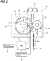
- FIG. 2 is a sectional schematic view of the fixing device 50.
- the fixing device 50 includes the fixing belt 20, the pressure roller 22, the heater 16 that generates heat with energization, and a heater holder 17 that holds the heater 16.
- the fixing device 50 includes a guide member 23, a fixing paper discharge roller 26, a main thermistor 19, and a sub-thermistor 18.
- the pressure roller 22 is formed by forming, with injection molding, a silicone rubber layer having thickness of approximately 3 mm on a core bar made of stainless steel and coating, on the silicone rubber layer, a PFA resin tube having thickness of approximately 40 ⁇ m. Both end portions of the core bar of the pressure roller 22 are rotatably held by a not-shown bearing attached to a frame 24. The pressure roller 22 rotates with the driving force of the not-shown driving source.
- the fixing belt 20 is an endless cylindrical member and is loosely externally fit in the heater holder 17. Both end portions of the heater holder 17 in a rotational axis direction of the pressure roller 22 are urged toward the pressure roller 22 by a not-shown urging mechanism with force of 98 N on one side and 196 N in total. Consequently, the heater 16 is pressed against the pressure roller 22 via the fixing belt 20 and the fixing nip portion N is formed. Note that the urging mechanism is configured to be able to release the urging in order to remove the sheet S during jam recovery.
- the fixing belt 20 in contact with the pressure roller 22 is driven to rotate around the outside of the heater holder 17 while bringing the inner circumferential surface of the fixing belt 20 into contact with and sliding the inner circumferential surface on the heater 16 with a frictional force.
- grease is applied to the inner circumferential surface of the fixing belt 20.
- the main thermistor 19 is provided in contact with the rear surface of the heater 16 and detects the temperature of the heater 16.
- the sub-thermistor 18 is provided elastically in contact with the inner circumferential surface of the fixing belt 20 and detects the temperature of the fixing belt 20.
- the main thermistor 19 and the sub-thermistor 18 are connected to a CPU 21 via a not-shown A/D converter.
- the CPU 21 controls energization to the heater 16 by a heater driving circuit 28 based on outputs of the main thermistor 19 and the sub-thermistor 18 and performs temperature adjustment control for the heater 16.
- the main thermistor 19 is disposed near the center in the longitudinal direction of the heater 16.
- the sub-thermistor 18 is provided near an end portion in the longitudinal direction of the fixing belt 20.
- the guide member 23 comes into contact with the sheet S to guide the sheet S to the fixing nip portion N.
- the guide member 23 is formed of polyphenylene sulfide (PPS) resin in this embodiment.
- the sheet S bearing an unfixed toner image is guided into the fixing nip portion N.
- the sheet S is nipped and conveyed with a toner image bearing surface side in contact with the outer circumferential surface of the fixing belt 20.
- the heat of the heater 16 is applied to the toner image on the sheet S via the fixing belt 20.
- the unfixed toner image is melted and fixed on the sheet S.
- the sheet S passed through the fixing nip portion N is curvature-separated from the fixing belt 20 and conveyed to the discharge roller 70 side by the fixing paper discharge roller 26.
- the sheet S conveyed to the fixing device 50 When the sheet S conveyed to the fixing device 50 is large, in the fixing nip portion N, the sheet S passes substantially the entire region in a sheet width direction orthogonal to a conveying direction of the sheet S. Consequently, the heat of substantially the entire region of the fixing nip portion N is taken by the sheet S. The temperature of the fixing nip portion N changes to substantially fixed temperature in the sheet width direction.
- the sheet S conveyed to the fixing device 50 is small, in the fixing nip portion N, the sheet S passes only near the center in the sheet width direction. Accordingly, in fixing nip portion N, the heat near the center in the sheet width direction is taken by the sheet S but the heat at both the end portions is not taken by the sheet S. The temperature at both end portions is high compared with the temperature near the center.
- the image forming apparatus H includes fans 95 and 96 and a duct for cooling 30 as the cooling portion that cools the fixing nip portion N.
- FIG. 3 is a schematic diagram of the fixing device 50, the fans 95 and 96, and the duct for cooling 30.
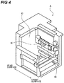
- FIG. 4 is an internal explanatory diagram of the image forming apparatus H and is a perspective view of a state in which a part of the exterior of the apparatus main body is made transparent.
- FIG. 5 is a graph for explaining driving timing of the fans 95 and 96.
- the two fans 95 and 96 and the duct for cooling 30 for cooling the fixing belt 20 are provided at both the end portions in a rotational axis direction of the fixing belt 20.
- the duct for cooling 30 guides the air to both the end portions of the fixing belt 20, that is, non-passage regions where the sheet S having a small size does not pass in the fixing belt 20 when the fixing device 50 performs the fixing process on the sheet S having the small size.
- Driving of the fans 95 and 96 is turned on when a detected temperature of the sub-thermistor 18 is equal to or higher than a predetermined temperature and is turned off when the detected temperature is equal to or lower than the predetermined temperature.
- a centrifugal fan such as a sirocco fan is used as the fans 95 and 96.
- fans of other types can also be used.
- the duct unit 200 is attached to an apparatus main body 1.
- an upper cover 111 and a lower cover 112 are provided as an exterior cover (a cover portion).
- the duct unit 200 is attached to the apparatus main body 1 via the upper cover 111 and the lower cover 112.
- the duct unit 200 forms a channel for exhausting the air warmed by the fixing device 50 to the outside of the apparatus main body 1.
- a discharge amount standard for ultrafine particles is specified. It is also desired to reduce a discharge amount of ultrafine particles in the image forming apparatus H. Therefore, the duct unit 200 is mounted on the image forming apparatus H in order to perform dedusting of the air warmed by the fixing device 50.
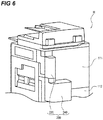
- FIG. 6 is a perspective view of the image forming apparatus H viewed from the rear surface side.
- the duct unit 200 is provided in the exterior of the image forming apparatus H to project to the rear (the rear surface side). That is, the duct unit 200 projects to the rear (the rear surface side) with respect to the planes of the upper cover 111 and the lower cover 112 functioning as the exterior cover.
- the duct unit 200 is configured from an upper unit 220 including an upper duct 224 and a lower unit 240 including a lower duct 241 coupled to the upper duct 224.
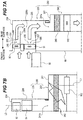
- FIGS. 7A and 7B are schematic diagrams of the duct unit 200.
- a fan 91 (a second fan) and a fan 92 (the second fan) for performing heat exhaust are provided near the fixing device 50.
- the fans 91 and 92 are respectively held by fan holders 280.
- the fan holders 280 are fastened to a rear side plate 80 ( FIG. 4 ).
- the fan 91 (a lower fan) exhausts the air around the fixing device 50.
- the fan 92 (an upper fan) is disposed near a conveyance path for the sheet S further upward (on a sheet conveying direction downstream side) than the fan 91 and exhausts the air around a discharging portion 75 to the outside of the apparatus.
- the discharging portion 75 is a space above the fixing device 50 and is a space around the discharge roller 70.
- the fan 91 and the fan 92 are provided further on the rear surface side of the image forming apparatus H than the rear side plate 80 ( FIG. 4 ).
- the air including the dust generated in the fixing device 50 is exhausted from an exhaust port 227 of the apparatus main body 1 by an air current generated by the fan 91 and carried into the upper duct 224 from an air supply port 230 (a first air supply port) of the upper duct 224.
- the air including the dust carried upward by the natural convection is exhausted from an exhaust port 228 (a main body exhaust port) of the apparatus main body 1 by an air current generated by the fan 92 and is carried into the upper duct 224 from an air supply port 231 (a second air supply port) of the upper duct 224.
- the upper duct 224 includes the two air supply ports 230 and 231 and includes an inner duct 233 provided on the inner surface of a cover member 225 in order to guide the air exhausted from the inside of the apparatus main body 1 via the respective air supply ports 230 and 231.
- the upper duct 224 includes an outer duct 226 that is coupled to the inner duct 233 and the lower duct 241 of the lower unit 240 and guides the air exhausted from the inside of the apparatus main body 1 via the inner duct 233 to the lower unit 240.
- the upper duct 224 is configured from the inner duct 233 and the outer duct 226.
- the airs exhausted from the exhaust ports 227 and 228 are respectively partitioned by a partition wall portion 229a, which is a part of the inner duct 233, and, thereafter, merge in a merging portion 229b and carried to the lower duct 241 via the outer duct 226. That is, the partition wall portion 229a partitioning the air supplied from the air supply port 230 and the air supplied from the air supply port 231 is provided further on an upstream side in a flowing direction of the air than the merging portion 229b.
- the air carried to the lower duct 241 is carried to a duct exhaust port 244 (a third exhaust port) side by an air current generated by a fan 102 (a third fan).
- a filter 260 provided on an exhaust path between the exhaust ports 227 and 228 and the duct exhaust port 244, the air is exhausted to the outside of the image forming apparatus H from the duct exhaust port 244.
- the filter 260 is disposed further on a downstream side in the flowing direction of the air than the merging portion 229b in which the air supplied from the air supply port 230 and the air supplied from the air supply port 231 merge. Consequently, compared with a configuration in which the airs merge in the filter 260, it is possible to reduce an area of a surface included in the filter 260 and reduce the filter 260 in size.
- a center line L1 of the fan 102 and a center line L2 of the upper duct 224 are arranged not to overlap. Consequently, it is possible to cause the air in the lower duct 241 to flow in the radial direction, cause the air to pass in a wide range of the filter 260, and efficiently collect the dust.
- FIG. 8 and FIG. 9 are perspective views of the duct unit 200.
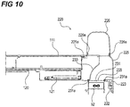
- FIG. 10 and FIG. 11 are sectional views of the duct unit 200 respectively taken along an L-L cross section shown in FIG. 8 and an H-H cross section shown in FIG. 9 .
- FIG. 12 is a sectional view of the duct unit 200 taken along a J-J cross section shown in FIG. 9 .
- FIG. 8 and FIG. 10 are views showing a case in which the upper unit 220 is in a closed state.
- FIG. 9 , FIG. 11 , and FIG. 12 are views showing a case in which the upper unit 220 is in an open state.
- the upper unit 220 includes shaft portions 221a and 221b.
- the shaft portions 221a and 221b are coaxially disposed and inserted into not-shown hole portions formed in the upper cover 111, which is the exterior of the apparatus main body 1 of the image forming apparatus H. Therefore, the upper unit 220 is supported by the upper cover 111 to be rotatable around the shaft portions 221a and 221b.
- the upper unit 220 turns to open and close with respect to the apparatus main body 1 of the image forming apparatus H. It is detected by an open and close sensor 25 functioning as detecting means that the upper unit 220 is in an open state with respect to the apparatus main body 1.
- the upper unit 220 is configured by the cover member 225 forming the exterior cover and the upper duct 224 provided on the inside of the cover member 225.
- the cover member 225 is formed as an open and close cover for exposing an interface portion 130 such as a LAN cable connecting portion 122 and an HDD inserting portion 121a provided on the apparatus main body 1 side opposed to the cover member 225.
- the interface portion 130 is disposed on the rear surface side of the apparatus main body 1, that is, the opposite side of a side surface to which the sheet processing apparatus is attached in the left-right direction. That is, the interface portion 130 is disposed on a side where the fixing device 50 is disposed in the left-right direction.
- a hard disk drive 121 (hereinafter, HDD 121) can be inserted into and removed from the HDD inserting portion 121a. That is, in a state in which the upper unit 220 is closed, the interface portion 130 provided in the apparatus main body 1 is provided in a position covered by the inner duct 233 of the duct unit 200. Accordingly, the interface portion 130 is accessible when the upper unit 220 is opened.
- the HDD 121 can be inserted and removed and a not-shown LAN cable can be connected.
- an electric contact of a not-shown connecting portion of the interface portion 130 and an electric contact of the HDD 121 are electrically connected.
- a sheet metal 223 for magnet catch is provided in the cover member 225.
- a magnet catch 222 is provided in a portion of the upper cover 111 opposed to the sheet metal 223.
- the cover member 225 is configured to be attractable to the apparatus main body 1 side (the apparatus main body side) by the magnet catch 222.
- the magnet catch 222 urges the cover member 225 in a closing direction with a magnetic force via the sheet metal 223, attracts the sheet metal 223, and holds the cover member 225 in a closed state. That is, the upper unit 220 is held in a closed state by the magnetic force of the magnet catch 222. Note that, in this embodiment, the upper unit 220 uses the magnet catch 222 in order to maintain the closed state. However, a configuration may be adopted in which the upper unit 220 is urged in a closing direction by other urging means.
- the air supply port 230 is coupled to the exhaust port 227 (a first exhaust port) from which the air in the apparatus main body 1 is discharged by the fan 91.
- the air supply port 231 is coupled to the exhaust port 228 (a second exhaust port) from which the air in the apparatus main body 1 is discharged by the fan 92.
- the outer duct 226 of the upper duct 224 is coupled to the lower duct 241 included in the lower unit 240.
- the inner duct 233 functioning as a first duct is provided to be capable of opening and closing with respect to the apparatus main body 1.
- an exhaust path from the exhaust ports 227 and 228 to the duct exhaust port 244 is formed via the inner duct 233.
- the interface portion 130 is exposed to be accessible.
- the lower duct 241 is configured as a second duct fixed to the apparatus main body 1.
- the air warmed by the fixing device 50 is exhausted from the exhaust ports 227 and 228 by the fans 91 and 92 and supplied to the inner duct 233 of the upper duct 224 from the air supply ports 230 and 231. Thereafter, the air is carried from the inner duct 233 to the outer duct 226 and from the outer duct 226 to the lower duct 241. Note that, in a state in which the upper unit 220 of the duct unit 200 is closed with respect to the apparatus main body 1, the HDD 121 is prevented by the inner duct 233 from being exposed to an air current. Consequently, the high-temperature air discharged from the exhaust port 228 is prevented from directly touching the HDD 121.
- a sealing member 231a is fixed to the air supply port 231 by a double sided tape in order to seal a gap of a coupling portion to the exhaust port 228.
- the size of the gap fluctuates according to molding fluctuation of a single component, attachment backlash, or the like. Therefore, the sealing member 231a is preferably configured by compressing an elastic member thicker than the gap.
- OPSEALER JKX-1105 manufactured by SANWAKAKO CO., LTD. is used as the sealing member 231a.
- a sealing member 226a is fixed to the outer duct 226 by a double sided tape in order to seal a gap of a fixing portion to the cover member 225.
- the sealing member 226a is preferably configured to compress an elastic member like the sealing member 231a.
- CALMFLEX F-2 manufactured by INOAC CORPORATION is used as the sealing member 226a.
- a sealing member 241a is fixed to the lower duct 241 by a double sided tape in order to seal a gap of a coupling portion to the outer duct 226.
- OPSEALER JKX-1105 manufactured by SANWAKAKO CO., LTD.
- PF-050H manufactured by DIC Corporation
- DIC Corporation is used for the surface of the sealing member 241a in order to suppress wear of the sealing member 241a due to opening and closing of the upper unit 220.
- the sealing member 241a When the upper unit 220 is opened and closed, in order to suppress wear of the sealing member 241a, it is desirable to compress the sealing member 241a in a direction (in this embodiment, the horizontal direction) orthogonal to the rotational axis direction of the upper unit 220.
- a coupling portion 250 to the lower duct 241 is formed to conform to the external shape of the outer duct 226, the outer duct 226 and the lower duct 241 interfere when the upper unit 220 is opened and closed.
- the coupling portion 250 of the lower duct 241 and the outer duct 226 is configured by a region F conforming to the external shape of the outer duct 226 and a region G conforming to a track on which an end portion 225a of the cover member 225 passes when the upper unit 220 rotates. Consequently, the outer duct 226 and the lower duct 241 do not interfere when the upper unit 220 is opened and closed.
- the sealing member 241a can be compressed in a direction orthogonal to the axial direction of the shaft portions 221a and 221b.
- the detachably attachable configuration includes an open-closable configuration.
- a state in which the upper unit 220 is attached to the exterior cover is equal to a closed state of the upper unit 220 with respect to the exterior cover and is a state in which the upper unit 220 covers the interface portion 130.
- a state in which the upper unit 220 is not attached to the exterior cover is equal to an open state of the upper unit 220 with respect to the exterior cover and is a state in which the upper unit 220 exposes the interface portion 130.
- a configuration in which the upper unit 220 is detachably attachable to the apparatus main body 1 explained above includes a configuration in which the upper unit 220 can be easily detached from the apparatus main body 1 without detaching a fastening tool such as a screw More specifically, the state is a state in which the upper unit 220 is attached to the upper cover 111 functioning as the exterior cover by snap-fit or the like and means a configuration in which the upper unit 220 can be detached from the upper cover 111 without using a tool. In this way, by configuring the upper unit 220 to be easily detachably attachable to the exterior cover, it is possible to suppress exhaust efficiency of the duct unit 200 from being deteriorated while making it easy to access the interface portion 130.
- FIG. 13 is a perspective view of the lower unit 240 in a state in which the fan holders 280 included in the lower unit 240 are detached.
- FIG. 14 is a perspective view of the lower unit 240 in a state in which the lower duct 241 and the filter 260 included in the lower unit 240 are detached. Note that FIG. 14 is a diagram of a state in which the upper duct 224 is also detached.
- the upper duct 224 side of the lower duct 241 is opened. This opened portion and the outer duct 226 are coupled.
- the lower duct 241 is screw-fixed to fixed portions 280a, 111a, and 112a provided in the upper cover 111, the lower cover 112, and the fan holders 280.
- the upper cover 111 (a first plate-like member) and the lower cover 112 (a second plate-like member), which are plate-like members, are the exterior of the apparatus main body 1.
- an air channel is formed by the lower duct 241, the upper cover 111, and the lower cover 112.
- a sealing member 111b is provided in order to seal a gap of a coupling portion to the lower duct 241.
- OPSEALER JKX-1105 manufactured by SANWAKAKO CO., LTD.
- the sealing member 111b is stuck to a rib 111d provided in the upper cover 111.
- the fan 102 and the filter 260 are provided on the inside of the lower duct 241.
- the duct exhaust port 244 is provided in a lower part of the lower duct 241.
- the duct exhaust port 244 is an exhaust port provided at a downstream end portion in a direction in which the air flows in the lower duct 241.
- the filter 260 has a configuration in which a filter material 262 is fixed to a frame body 261 made of resin.
- the filter material 262 is provided in a pleat shape in the frame body 261. Consequently, a surface area of the filter material 262 is increased to improve dust collection efficiency.
- the filter material 262 is divided into two to hold the frame body 261 to secure strength. Note that, in this embodiment, FM-9406WP (manufactured by Japan Vilene Company, Ltd.) is used as the filter material 262.
- a position in the up-down direction of the filter 260 is restricted by four positioning portions 243.
- the filter 260 is held in a form sandwiched by the inner side of the lower duct 241 and the upper cover 111.
- a sealing member 260a for sealing gaps between the frame body 261 of the filter 260 and the lower duct 241, the upper cover 111, and the lower cover 112 is provided in the entire circumference of the frame body 261.
- CALMFLEX F-2 manufactured by INOAC CORPORATION
- the fan 102 is held by the fan holders 280 (holding members).
- the fan holders 280 are screw-fixed to the lower cover 112.
- the fan 102 is provided further on a downstream side of an air current exhausted from the duct exhaust port 244 than the filter 260.
- the fan 102 generates an air current for exhaust from the duct exhaust port 244 of the lower duct 241.
- the duct unit 200 is configured to project to the rear surface side of the apparatus main body 1 with respect to a plane to which the fan holder 280 is fixed in the lower cover 112 functioning as the exterior cover.
- the duct unit 200 is configured to project further to the rear surface side of the image forming apparatus H than the rib 111d provided in the upper cover 111 functioning as the exterior cover.
- the interval between the filter 260 and the fan 102 is secured approximately 40 mm to maintain the dust collection efficiency. That is, it is preferable that a distance on the exhaust path between the filter 260 and the fan 102 is 40 mm or more.
- a sealing member 280c is provided in the fan holder 280 in order to seal a gap between the fan holders 280 and the lower cover 112. Further, a sealing member 280d is provided in order to seal a gap between the fan holder 280 and the lower duct 241.
- OPSEALER JKX-1105 manufactured by SANWA KAKO CO., LTD. is used as the sealing members 280c and 280d.
- a bundle wire 283 (an electric wire) for electrically connecting the fan 102 and a not-shown substrate provided on the inside of the image forming apparatus H is held by the fan holder 280.
- the bundle wire 283 electrically connects the fan 102 and a not-shown substrate provided in the apparatus main body 1 (on the inner side of the upper cover 111 and the lower cover 112) via a relay connector 284.
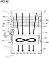
- FIG. 15 is a sectional view of the lower unit 240 taken along a K-K cross section shown in FIG. 14 .
- FIG. 15 is a sectional view of a state in which the lower duct 241 and the filter 260 are attached.
- an opening portion 285 for inserting through the bundle wire 283 from the inside of the apparatus main body 1 of the image forming apparatus H is formed in a position between the upper cover 111 and the lower cover 112 functioning as the exterior of the apparatus main body 1 opposed to the lower duct 241.
- an opposed portion 280b disposed to be opposed to the opening portion 285 at an interval and covering the opening portion 285 when viewed from a direction (the front-rear direction of the image forming apparatus H) orthogonal to the rotational axis direction of the fan 102 (a direction of a line D shown in FIG. 15 ) is provided.
- the opposed portion 280b extends to incline in a direction (an opposite direction) opposite to a flow of the air flowing in the lower duct 241.
- the distal end portion of the opposed portion 280b is present in a position further away from the opening portion 285 than the proximal end portion of the opposed portion 280b.
- the distal end portion of the opposed portion 280b is inclined to be further away from the upper cover 111 than the proximal end portion.
- the opposed portion 280b By providing the opposed portion 280b in this way, when the air flows in the duct unit 200, it is possible to generate a swirling air current E near the opening portion 285.
- the air in the apparatus main body 1 (further on the inner side of the apparatus main body 1 than the upper cover 111 and the lower cover 112) can be suppressed from flowing into the lower duct 241 from the opening portion 285 by this air current E. Accordingly, it is possible to suppress occurrence of an adverse effect in which, for example, an unintended flow of the air occurs in the apparatus main body and the toner scatters. It is possible to improve exhaust efficiency of the lower duct 241.
- an angle (an inclination angle of the opposed portion 280b) ⁇ formed by the rotational axis direction of the fan 102 and the opposed portion 280b with a direction of an inclined surface extending along a channel of the air is 10°.
- a lower end portion 111c on a side close to the lower cover 112 (the opening portion 285) is bent to the inner side of the lower duct. That is, the lower end portion 111c of the upper cover 111 is inclined toward a direction away from the lower cover 112 (the outer side of the apparatus main body 1).
- an opening width of the opening portion 285 can be maintained. Therefore, it is easy to secure a space for allowing a bundle wire of the fan 102 and the other wires to pass. Even in a configuration in which the opening portion 285 for wiring the bundle wire 283 is provided, it is possible to suppress the air in the apparatus main body 1 from flowing into the duct unit 200 from the opening portion 285.
- FIG. 16 is a graph showing a temperature distribution in the duct of the duct unit 200.
- the duct unit 200 is configured to be provided on the outer side of the image forming apparatus H and exposed to the outside air. Accordingly, whereas an internal temperature near an inlet of the upper duct 224 is as high as 76°C, an internal temperature near an inlet 241x of the lower duct 241 and further on an upstream side than the filter 260 in a flowing direction of the air drops to 47°C.
- the filter 260 is provided in a position where a temperature difference between a first temperature of the air in a duct inlet and a second temperature of the air passing in the filter 260 is at least 20°C or more (a predetermined temperature difference) because the duct unit 200 is exposed to the outside air.
- the inlet of the upper duct 224 is the air supply port 230 and the air supply port 231 and means an upstream end portion side of the upper duct 224 in the direction in which the air flows in the duct unit 200.
- the inlet 241x of the lower duct 241 means an upstream end portion side of the lower duct 241 in the direction in which the air flows in the duct unit 200 and means an end portion side on the opposite side of the duct exhaust port 244 across the filter 260.
- the duct unit 200 is configured to be exposed to the outside air to lower the temperature of the air in the duct before the air reaches the filter 260. Consequently, condensation of dust sufficiently advances near the filter 260. Since the dust condenses, the dust is easily collected by the filter 260. Therefore, it is possible to improve dust collection efficiency by the filter 260.
- the temperature of the air drops to 41°C near the duct exhaust port 244. Accordingly, it is possible to suppress the temperature of the air exhausted from the duct exhaust port 244 from rising. It is possible to suppress unpleasant feeling from being given to the user.
- FIG. 17 is a graph showing a relation between a flow rate A of the air supplied from the air supply port 230 of the upper duct 224, a flow rate B of the air supplied from the air supply port 231, and a flow rate C of the air exhausted from the duct exhaust port 244 and an intra-apparatus temperature of the image forming apparatus H.
- the flow rate A of the air supplied from the air supply port 230 of the upper duct 224 is substantially equal to a flow rate of the air discharged from the exhaust port 227 of the apparatus main body 1 by the fan 91.
- the flow rate B of the air supplied from the air supply port 231 is substantially equal to a flow rate of the air discharged from the exhaust port 228 of the apparatus main body 1 by the fan 92.
- the flow rate C of the air exhausted from the duct exhaust port 244 is substantially equal to a flow rate of the air discharged to the outside of the duct unit 200 by the fan 102.
- a flow rate of the air per unit time supplied from the air supply ports 230 and 231 is set to be equal to or lower than a flow rate of the air per unit time exhausted from the duct exhaust port 244. That is, the relation among the flow rates A, B, and C is set to C ⁇ A + B. Consequently, it is possible to sufficiently exhaust the air warmed by the fixing device 50 and suppress a temperature rise of the image forming apparatus H.
- a configuration is adopted in which the relations among the flow rates explained above is satisfied by increasing the number of rotations of the fan 102 with respect to the fans 91 and 92 or increasing the size of the fan 102 itself.
- FIG. 18 is a disposition diagram of the duct unit 200 and electric units at the time when the image forming apparatus H is viewed from the rear surface side.
- the controller substrate 120 including an electronic circuit that performs arithmetic processing for outputting received image data as an image is disposed on the rear surface side of the apparatus main body 1 of the image forming apparatus H.
- a power supply substrate 123 that supplies electric power to the apparatus main body, an engine control substrate 124, the HDD 121, and the like are disposed.
- the upper cover 111 and the lower cover 112 are provided on the outer side as the exterior cover of the image forming apparatus H to cover the controller substrate 120, the power supply substrate 123, the engine control substrate 124, and the like functioning as electric substrates. That is, the controller substrate 120, the power supply substrate 123, the engine control substrate 124 are provided on the inner side of the upper cover 111 and the lower cover 112.
- fans 97 and 98 (first fans) for cooling the electronic components mounted on these substrates are provided near the controller substrate 120 and the power supply substrate 123.
- a louver 115 provided in the lower cover 112 functioning as the exterior of the image forming apparatus H is provided in a position overlapping the engine control substrate 124 when viewed from the rear surface side of the apparatus main body 1 of the image forming apparatus H.
- the duct unit 200 is provided in a position not overlapping the louvers 113, 114, and 115 of the image forming apparatus H with respect to the upper cover 111 and the lower cover 112.
- the duct unit 200 is provided to project further to the rear surface side of the image forming apparatus H than surfaces on which the louvers 113, 114, and 115 are provided in the upper cover 111 and the lower cover 112 functioning as the exterior.
- the air passing in the duct unit 200 is the air having relatively high temperature warmed by the fixing device 50. Accordingly, when the duct unit 200 is located in a position overlapping the electric units when the image forming apparatus H is viewed from the rear surface side, the temperature of the electric units easily rises with the air having high temperature passing in the duct unit 200.
- the duct unit 200, the controller substrate 120, the HDD 121, the power supply substrate 123, and the engine control substrate 124 are disposed not to overlap when viewed from the rear surface side of the apparatus main body 1 of the image forming apparatus H. That is, when the image forming apparatus H is viewed from the rear surface, the upper duct 224 is disposed beside the controller substrate 120 and the lower duct 241 is disposed such that a part of the lower duct 241 is located below the controller substrate 120 in the vertical direction. When the image forming apparatus H is viewed from the rear surface, the duct unit 200 is disposed in a position not overlapping a CPU mounted on the controller substrate 120 and a CPU mounted on the power supply substrate 123. Consequently, it is possible to exhaust the air in the image forming apparatus H to the outside of the apparatus via the duct unit 200 without hindering cooling efficiency of the electric units.
- the configuration is adopted in which the duct unit 200 is disposed avoiding the controller substrate 120, the HDD 121, the power supply substrate 123, and the engine control substrate 124.
- the duct unit 200 is not limited to this configuration. Other configurations may be adopted if the duct unit 200 is at least disposed in a position avoiding the electric units susceptible to heat.
- a configuration may be adopted in which the duct unit 200 is provided, in the front-rear direction of the apparatus main body 1, in a position overlapping a substrate of a driving system such as a motor driver on which an electronic component susceptible to heat is not mounted.
Landscapes
- Physics & Mathematics (AREA)
- General Physics & Mathematics (AREA)
- Control Or Security For Electrophotography (AREA)
Abstract
Description
- The present invention relates to an image forming apparatus such as an electrophotographic copying machine or an electrophotographic printer.
- An image forming apparatus of an electrophotographic system includes a fixing portion that melts a toner image on a sheet with heat and fixes the toner image on the sheet. In a fixing process of this fixing portion, the toner is sometimes transferred to the fixing portion. Therefore, there has been known a configuration in which wax is included in the toner, the wax is oozed from the toner during the fixing process and interposed in an interface between the fixing portion and the toner image, and the transfer of the toner to the fixing portion is suppressed.
- However, when heat is applied to the wax included in the toner, a part of the wax is vaporized and the vaporized wax is cooled in the air and condensed to be dust. Therefore, Japanese Patent Laid-Open No.
2017-32833 - On the rear surface side of the image forming apparatus, in general, various substrates such as a controller substrate including a CPU that executes various programs and performs an image forming operation and a power supply substrate that controls commercial power supplies different depending on countries to be a fixed value are disposed. Electronic components (elements) mounted on the controller substrate and the power supply substrate are susceptible to heat. When the heat exceeds allowable temperatures respectively set for the electronic components, the electronic components are likely to be broken.
- In the configuration described in Japanese Patent Laid-Open No.
2017-32833 - Therefore, in view of the above, an object of the present invention is to provide an image forming apparatus that, when the air warmed by a fixing portion passes on the inside of a duct, can suppress the temperatures of electronic components mounted on a substrate in an apparatus main body from rising.
- A representative configuration of an image forming apparatus according to the present invention for achieving the object described above is an image forming apparatus that heats, in a fixing portion, a toner image transferred onto a recording material, fixes the toner image on the recording material, and forms an image, the image forming apparatus including: a substrate on which electronic components are mounted; a cover portion that covers the electric substrate on a rear surface of the image forming apparatus, at least a part of the cover portion forming an exterior of the image forming apparatus; a main body exhaust port for exhausting air on an inside of the cover portion to an outside of the cover portion; a duct unit attached to the cover portion, the duct unit forming an exhaust path for exhausting the air exhausted from the main body exhaust port to an outside of the duct unit; a filter provided on an inside of the duct; and a fan that is fixed to the cover portion on an inside of the second duct and exhausts the air in the duct unit, wherein the duct unit projects to the rear surface side of the image forming apparatus with respect to a plane to which the fan is fixed in the cover portion, and the duct unit is disposed in a position not overlapping the electronic components when the image forming apparatus is viewed from the rear surface side.
- According to the present invention, in the image forming apparatus, when the air warmed by the fixing portion passes on the inside of the duct, it is possible to suppress the temperatures of the electronic components mounted on the substrate in an apparatus main body from being raised by this air.
- Further features of the present invention will become apparent from the following description of exemplary embodiments with reference to the attached drawings.
-
-
FIG. 1 is a sectional schematic view of an image forming apparatus. -
FIG. 2 is a sectional schematic view of a fixing device. -
FIG. 3 is a schematic diagram of the fixing device, a fan, and a duct for cooling. -
FIG. 4 is an internal explanatory diagram of the image forming apparatus. -
FIG. 5 is a graph for explaining driving timing of the fan. -
FIG. 6 is a perspective view of the image forming apparatus viewed from the rear surface side. -
FIGS. 7A and 7B are schematic diagrams of a duct unit. -
FIG. 8 is a perspective view of the duct unit. -
FIG. 9 is a perspective view of the duct unit. -
FIG. 10 is a sectional view of the duct unit. -
FIG. 11 is a sectional view of the duct unit. -
FIG. 12 is a sectional view of the duct unit. -
FIG. 13 is a perspective view of a lower unit. -
FIG. 14 is a perspective view of the lower unit. -
FIG. 15 is a sectional view of the lower unit. -
FIG. 16 is a graph showing a temperature distribution in a duct of the duct unit. -
FIG. 17 is a graph showing a relation between a flow rate of the air supplied from an air supply port of the duct in the duct unit and a flow rate of the air exhausted from a duct exhaust port and an intra-apparatus temperature of the image forming apparatus. -
FIG. 18 is a disposition diagram of the duct unit and electric units at the time when the image forming apparatus is viewed from the rear surface side. - First, an overall configuration of an image forming apparatus according to a first embodiment of the present invention is explained below together with operation during image formation with reference to the drawings together. Note that dimensions, materials, shapes, relative dispositions, and the like of described constituent components are not meant to limit the scope of the present invention only thereto unless specifically described otherwise.
-
FIG. 1 is a sectional schematic view of an image forming apparatus H according to this embodiment. As shown inFIG. 1 , the image forming apparatus H is an image forming apparatus of an electrophotographic system that forms an image on a sheet using toners of four colors of yellow, magenta, cyan, and black. The image forming apparatus H includes an image forming portion that transfers a toner image onto a sheet and forms an image, a sheet feeding portion that supplies the sheet toward the image forming portion, and a fixing portion that fixes the toner image on the sheet. - The image forming portion includes process units 103 (103Y, 103M, 103C, and 103K) that forms toner images of the colors using the toners of the colors described above. The image forming portion includes exposing devices 104 (104Y, 104M, 104C, and 104K), an
intermediate transfer belt 6, asecondary transfer roller 8, and a secondarytransfer counter roller 9. - The respective process units 103 include
photosensitive drums 3,electrifying rollers 4, developing devices including developingsleeves 5, and primary transfer rollers 7. Note that theprocess units - Subsequently, an image forming operation is explained. First, when a
controller substrate 120 shown inFIG. 18 receives an image forming job signal, a sheet S (a recording material) stacked and stored in asheet cassette 101 is sent into aregistration roller 12 by apickup roller 2, afeeding roller 10, and aconveying roller 11. After skew correction and timing correction for the sheet S are performed by theregistration roller 12, the sheet S is sent into a secondary transfer portion formed by thesecondary transfer roller 8 and the secondarytransfer counter roller 9. - On the other hand, in the image forming portions first, the surfaces of the
photosensitive drums 3 are electrified by theelectrifying rollers 4. Thereafter, image data transmitted from a not-shown external apparatus or the like is processed by thecontroller substrate 120. The exposing devices 104 irradiate laser light onto the surfaces of thephotosensitive drums 3. Consequently, electrostatic latent images corresponding to the image data are formed on the surfaces of thephotosensitive drums 3. - Thereafter, the toners of the respective colors are caused to adhere to the electrostatic latent images formed on the surfaces of the
photosensitive drums 3 by the developingsleeves 5. Toner images are formed on the surfaces of thephotosensitive drums 3. A primary transfer bias is applied to the primary transfer rollers 7, whereby the toner images formed on the surfaces of thephotosensitive drums 3 are respectively primarily transferred to theintermediate transfer belt 6. Consequently, a full-color toner image is formed on the surface of theintermediate transfer belt 6. - Thereafter, the secondary
transfer counter roller 9 receiving a driving force from a not-shown driving source rotates, whereby theintermediate transfer belt 6 is driven to rotate and the toner image is transferred to the secondary transfer portion. A secondary transfer bias is applied to thesecondary transfer roller 8 in the secondary transfer portion, whereby the toner image on theintermediate transfer belt 6 is transferred onto the sheet S. - Subsequently, the sheet S, on which the toner image is transferred, is conveyed to a
fixing device 50. The fixingdevice 50 includes, as a fixing portion, a fixingbelt 20 including a heater 16 (FIG. 2 ) and apressure roller 22 that pressurizes the fixingbelt 20 and rotates with the driving force of the not-shown driving source to drive to rotate the fixingbelt 20. - The sheet S conveyed to the fixing
device 50 is subjected to heating and pressurizing processes while being nipped and conveyed in a fixing nip portion N formed by the fixingbelt 20 and thepressure roller 22. Consequently, the toner image on the sheet S is fixed on the sheet S. Thereafter, the sheet S, on which the toner image is fixed, is discharged to adischarge tray 106 by adischarge roller 70. - Note that, in this embodiment, paraffin wax is included in the toner. The wax melted by the heat of the fixing process is interposed on an interface between the fixing
belt 20 and the toner image to prevent the toner from adhering to the fixingbelt 20. A melting point of this wax is approximately 75°C. A target temperature of the fixing nip portion is 170°C. - Wax is not limited to the wax described above. A compound including a molecular structure of the wax such as a compound obtained by causing a wax molecular structure such as a hydrocarbon chain to react with a resin molecule of the toner can also be used. Another substance having releasing action such as silicon oil can also be used rather than the wax.
- When images are formed on both surfaces of the sheet S, the sheet S is guided to a reversing path 13 after a toner image is fixed on the front surface of the sheet S by the fixing
device 50. Thereafter, a reversingroller 14 reversely rotates in a state in which the reversingroller 14 nips the sheet S. After the front and rear surfaces of the sheet S are reversed through are-feeding path 15, the sheet S is sent to the secondary transfer portion again. Subsequently, an image is formed on the rear surface of the sheet S as on the front surface of the sheet S. Thereafter, the sheet S is discharged to thedischarge tray 106. - A not-shown sheet processing apparatus that performs a binding process, a folding process, and the like on the sheet S, on which the image is formed by the image forming portion, can be attached to the image forming apparatus H. In the image forming apparatus H in this embodiment, the sheet processing apparatus is connected to the left side in
FIG. 1 via a not-shown relay unit or the like. That is, the sheet processing apparatus is attached to the opposite side of the fixingdevice 50 in the left-right direction (the width direction) of the image forming apparatus H with respect to the image forming apparatus H. - Subsequently, the configuration of the fixing
device 50 is explained. -
FIG. 2 is a sectional schematic view of the fixingdevice 50. As shown inFIG. 2 , the fixingdevice 50 includes the fixingbelt 20, thepressure roller 22, theheater 16 that generates heat with energization, and aheater holder 17 that holds theheater 16. The fixingdevice 50 includes aguide member 23, a fixingpaper discharge roller 26, amain thermistor 19, and a sub-thermistor 18. - The
pressure roller 22 is formed by forming, with injection molding, a silicone rubber layer having thickness of approximately 3 mm on a core bar made of stainless steel and coating, on the silicone rubber layer, a PFA resin tube having thickness of approximately 40 µm. Both end portions of the core bar of thepressure roller 22 are rotatably held by a not-shown bearing attached to aframe 24. Thepressure roller 22 rotates with the driving force of the not-shown driving source. - The fixing
belt 20 is an endless cylindrical member and is loosely externally fit in theheater holder 17. Both end portions of theheater holder 17 in a rotational axis direction of thepressure roller 22 are urged toward thepressure roller 22 by a not-shown urging mechanism with force of 98 N on one side and 196 N in total. Consequently, theheater 16 is pressed against thepressure roller 22 via the fixingbelt 20 and the fixing nip portion N is formed. Note that the urging mechanism is configured to be able to release the urging in order to remove the sheet S during jam recovery. - When the
pressure roller 22 rotates, the fixingbelt 20 in contact with thepressure roller 22 is driven to rotate around the outside of theheater holder 17 while bringing the inner circumferential surface of the fixingbelt 20 into contact with and sliding the inner circumferential surface on theheater 16 with a frictional force. In order to secure a sliding property between theheater holder 17 and the inner circumferential surface of the fixingbelt 20, grease is applied to the inner circumferential surface of the fixingbelt 20. - The
main thermistor 19 is provided in contact with the rear surface of theheater 16 and detects the temperature of theheater 16. The sub-thermistor 18 is provided elastically in contact with the inner circumferential surface of the fixingbelt 20 and detects the temperature of the fixingbelt 20. Themain thermistor 19 and the sub-thermistor 18 are connected to aCPU 21 via a not-shown A/D converter. TheCPU 21 controls energization to theheater 16 by aheater driving circuit 28 based on outputs of themain thermistor 19 and the sub-thermistor 18 and performs temperature adjustment control for theheater 16. Note that themain thermistor 19 is disposed near the center in the longitudinal direction of theheater 16. The sub-thermistor 18 is provided near an end portion in the longitudinal direction of the fixingbelt 20. - The
guide member 23 comes into contact with the sheet S to guide the sheet S to the fixing nip portion N. Theguide member 23 is formed of polyphenylene sulfide (PPS) resin in this embodiment. - When the fixing process is performed, first, the sheet S bearing an unfixed toner image is guided into the fixing nip portion N. Subsequently, in the fixing nip portion N, the sheet S is nipped and conveyed with a toner image bearing surface side in contact with the outer circumferential surface of the fixing
belt 20. In this conveyance process, the heat of theheater 16 is applied to the toner image on the sheet S via the fixingbelt 20. The unfixed toner image is melted and fixed on the sheet S. Thereafter, the sheet S passed through the fixing nip portion N is curvature-separated from the fixingbelt 20 and conveyed to thedischarge roller 70 side by the fixingpaper discharge roller 26. - Subsequently, a cooling portion that cools the fixing nip portion N is explained.
- When the sheet S conveyed to the fixing
device 50 is large, in the fixing nip portion N, the sheet S passes substantially the entire region in a sheet width direction orthogonal to a conveying direction of the sheet S. Consequently, the heat of substantially the entire region of the fixing nip portion N is taken by the sheet S. The temperature of the fixing nip portion N changes to substantially fixed temperature in the sheet width direction. - In contrast, when the sheet S conveyed to the fixing
device 50 is small, in the fixing nip portion N, the sheet S passes only near the center in the sheet width direction. Accordingly, in fixing nip portion N, the heat near the center in the sheet width direction is taken by the sheet S but the heat at both the end portions is not taken by the sheet S. The temperature at both end portions is high compared with the temperature near the center. - In this case, when the temperature of the
heater 16 is raised in order to keep a fixing property in the center, the temperature in the center reaches a desired temperature but the temperature at both the end portions continues to rise and is likely to adversely affect the fixingdevice 50, for example, deform a member. Therefore, in order to suppress the temperature raise at both the end portions in the sheet width direction of the fixing nip portion N, the image forming apparatus H includesfans -
FIG. 3 is a schematic diagram of the fixingdevice 50, thefans FIG. 4 is an internal explanatory diagram of the image forming apparatus H and is a perspective view of a state in which a part of the exterior of the apparatus main body is made transparent.FIG. 5 is a graph for explaining driving timing of thefans - As shown in
FIGS. 3 to 5 , the twofans belt 20 are provided at both the end portions in a rotational axis direction of the fixingbelt 20. The duct for cooling 30 guides the air to both the end portions of the fixingbelt 20, that is, non-passage regions where the sheet S having a small size does not pass in the fixingbelt 20 when the fixingdevice 50 performs the fixing process on the sheet S having the small size. Driving of thefans - With such a configuration, it is possible to suppress the temperature of the non-passage regions from rising when the fixing process is continuously performed in the sheet S having the small size. Note that, in this embodiment, a centrifugal fan such as a sirocco fan is used as the
fans - Subsequently, an overview of a
duct unit 200 that performs dedusting of the air exhausted from the image forming apparatus H is explained. In the image forming apparatus H, theduct unit 200 is attached to an apparatus main body 1. On the rear surface side of the apparatus main body 1, anupper cover 111 and alower cover 112 are provided as an exterior cover (a cover portion). Theduct unit 200 is attached to the apparatus main body 1 via theupper cover 111 and thelower cover 112. Theduct unit 200 forms a channel for exhausting the air warmed by the fixingdevice 50 to the outside of the apparatus main body 1. - As explained above, when the heat is applied to the toner image on the sheet S for the fixing process in the fixing
device 50, a part of the wax included in the toner vaporizes. The vaporized wax is cooled and condensed in the air to be air including dust. It has been found by researches of the present inventor that most of this dust adheres to the vicinity of asheet introducing port 400 of the fixingdevice 50 and, in particular, under a high-temperature environment, the dust increases in diameter and easily adheres to the vicinity of thesheet introducing port 400. - In the BLUE ANGEL standard in Europe, a discharge amount standard for ultrafine particles is specified. It is also desired to reduce a discharge amount of ultrafine particles in the image forming apparatus H. Therefore, the
duct unit 200 is mounted on the image forming apparatus H in order to perform dedusting of the air warmed by the fixingdevice 50. -
FIG. 6 is a perspective view of the image forming apparatus H viewed from the rear surface side. As shown inFIG. 6 , theduct unit 200 is provided in the exterior of the image forming apparatus H to project to the rear (the rear surface side). That is, theduct unit 200 projects to the rear (the rear surface side) with respect to the planes of theupper cover 111 and thelower cover 112 functioning as the exterior cover. Theduct unit 200 is configured from anupper unit 220 including anupper duct 224 and alower unit 240 including alower duct 241 coupled to theupper duct 224. -
FIGS. 7A and 7B are schematic diagrams of theduct unit 200. As shown inFIG. 7A , a fan 91 (a second fan) and a fan 92 (the second fan) for performing heat exhaust are provided near the fixingdevice 50. Thefans fan holders 280. Thefan holders 280 are fastened to a rear side plate 80 (FIG. 4 ). - The fan 91 (a lower fan) exhausts the air around the fixing
device 50. The fan 92 (an upper fan) is disposed near a conveyance path for the sheet S further upward (on a sheet conveying direction downstream side) than thefan 91 and exhausts the air around a dischargingportion 75 to the outside of the apparatus. The dischargingportion 75 is a space above the fixingdevice 50 and is a space around thedischarge roller 70. Thefan 91 and thefan 92 are provided further on the rear surface side of the image forming apparatus H than the rear side plate 80 (FIG. 4 ). - The air including the dust generated in the fixing
device 50 is exhausted from anexhaust port 227 of the apparatus main body 1 by an air current generated by thefan 91 and carried into theupper duct 224 from an air supply port 230 (a first air supply port) of theupper duct 224. The air including the dust carried upward by the natural convection is exhausted from an exhaust port 228 (a main body exhaust port) of the apparatus main body 1 by an air current generated by thefan 92 and is carried into theupper duct 224 from an air supply port 231 (a second air supply port) of theupper duct 224. - The
upper duct 224 includes the twoair supply ports inner duct 233 provided on the inner surface of acover member 225 in order to guide the air exhausted from the inside of the apparatus main body 1 via the respectiveair supply ports upper duct 224 includes anouter duct 226 that is coupled to theinner duct 233 and thelower duct 241 of thelower unit 240 and guides the air exhausted from the inside of the apparatus main body 1 via theinner duct 233 to thelower unit 240. Theupper duct 224 is configured from theinner duct 233 and theouter duct 226. - The airs exhausted from the
exhaust ports partition wall portion 229a, which is a part of theinner duct 233, and, thereafter, merge in a mergingportion 229b and carried to thelower duct 241 via theouter duct 226. That is, thepartition wall portion 229a partitioning the air supplied from theair supply port 230 and the air supplied from theair supply port 231 is provided further on an upstream side in a flowing direction of the air than the mergingportion 229b. - The air carried to the
lower duct 241 is carried to a duct exhaust port 244 (a third exhaust port) side by an air current generated by a fan 102 (a third fan). After the dust is collected by afilter 260 provided on an exhaust path between theexhaust ports duct exhaust port 244, the air is exhausted to the outside of the image forming apparatus H from theduct exhaust port 244. - In this way, the
filter 260 is disposed further on a downstream side in the flowing direction of the air than the mergingportion 229b in which the air supplied from theair supply port 230 and the air supplied from theair supply port 231 merge. Consequently, compared with a configuration in which the airs merge in thefilter 260, it is possible to reduce an area of a surface included in thefilter 260 and reduce thefilter 260 in size. - As shown in
FIG. 7B , a center line L1 of thefan 102 and a center line L2 of theupper duct 224 are arranged not to overlap. Consequently, it is possible to cause the air in thelower duct 241 to flow in the radial direction, cause the air to pass in a wide range of thefilter 260, and efficiently collect the dust. - Subsequently, a detailed configuration of the
duct unit 200 is explained. -
FIG. 8 andFIG. 9 are perspective views of theduct unit 200.FIG. 10 andFIG. 11 are sectional views of theduct unit 200 respectively taken along an L-L cross section shown inFIG. 8 and an H-H cross section shown inFIG. 9 .FIG. 12 is a sectional view of theduct unit 200 taken along a J-J cross section shown inFIG. 9 .FIG. 8 andFIG. 10 are views showing a case in which theupper unit 220 is in a closed state.FIG. 9 ,FIG. 11 , andFIG. 12 are views showing a case in which theupper unit 220 is in an open state. - As shown in
FIG. 8 to FIG. 12 , theupper unit 220 includesshaft portions shaft portions upper cover 111, which is the exterior of the apparatus main body 1 of the image forming apparatus H. Therefore, theupper unit 220 is supported by theupper cover 111 to be rotatable around theshaft portions upper unit 220 turns to open and close with respect to the apparatus main body 1 of the image forming apparatus H. It is detected by an open andclose sensor 25 functioning as detecting means that theupper unit 220 is in an open state with respect to the apparatus main body 1. - The
upper unit 220 is configured by thecover member 225 forming the exterior cover and theupper duct 224 provided on the inside of thecover member 225. Thecover member 225 is formed as an open and close cover for exposing aninterface portion 130 such as a LANcable connecting portion 122 and anHDD inserting portion 121a provided on the apparatus main body 1 side opposed to thecover member 225. - In the image forming apparatus H in this embodiment, the
interface portion 130 is disposed on the rear surface side of the apparatus main body 1, that is, the opposite side of a side surface to which the sheet processing apparatus is attached in the left-right direction. That is, theinterface portion 130 is disposed on a side where the fixingdevice 50 is disposed in the left-right direction. - A hard disk drive 121 (hereinafter, HDD 121) can be inserted into and removed from the
HDD inserting portion 121a. That is, in a state in which theupper unit 220 is closed, theinterface portion 130 provided in the apparatus main body 1 is provided in a position covered by theinner duct 233 of theduct unit 200. Accordingly, theinterface portion 130 is accessible when theupper unit 220 is opened. TheHDD 121 can be inserted and removed and a not-shown LAN cable can be connected. When theHDD 121 is attached to theHDD inserting portion 121a, an electric contact of a not-shown connecting portion of theinterface portion 130 and an electric contact of theHDD 121 are electrically connected. - A
sheet metal 223 for magnet catch is provided in thecover member 225. Amagnet catch 222 is provided in a portion of theupper cover 111 opposed to thesheet metal 223. Thecover member 225 is configured to be attractable to the apparatus main body 1 side (the apparatus main body side) by themagnet catch 222. - The
magnet catch 222 urges thecover member 225 in a closing direction with a magnetic force via thesheet metal 223, attracts thesheet metal 223, and holds thecover member 225 in a closed state. That is, theupper unit 220 is held in a closed state by the magnetic force of themagnet catch 222. Note that, in this embodiment, theupper unit 220 uses themagnet catch 222 in order to maintain the closed state. However, a configuration may be adopted in which theupper unit 220 is urged in a closing direction by other urging means. - In the closed state of the
upper unit 220, theair supply port 230 is coupled to the exhaust port 227 (a first exhaust port) from which the air in the apparatus main body 1 is discharged by thefan 91. Theair supply port 231 is coupled to the exhaust port 228 (a second exhaust port) from which the air in the apparatus main body 1 is discharged by thefan 92. Theouter duct 226 of theupper duct 224 is coupled to thelower duct 241 included in thelower unit 240. - That is, the
inner duct 233 functioning as a first duct is provided to be capable of opening and closing with respect to the apparatus main body 1. When theupper unit 220 is closed with respect to the apparatus main body 1, an exhaust path from theexhaust ports duct exhaust port 244 is formed via theinner duct 233. When theupper unit 220 is opened with respect to the apparatus main body 1, theinterface portion 130 is exposed to be accessible. Note that thelower duct 241 is configured as a second duct fixed to the apparatus main body 1. - The air warmed by the fixing
device 50 is exhausted from theexhaust ports fans inner duct 233 of theupper duct 224 from theair supply ports inner duct 233 to theouter duct 226 and from theouter duct 226 to thelower duct 241. Note that, in a state in which theupper unit 220 of theduct unit 200 is closed with respect to the apparatus main body 1, theHDD 121 is prevented by theinner duct 233 from being exposed to an air current. Consequently, the high-temperature air discharged from theexhaust port 228 is prevented from directly touching theHDD 121. - A sealing
member 231a is fixed to theair supply port 231 by a double sided tape in order to seal a gap of a coupling portion to theexhaust port 228. The size of the gap fluctuates according to molding fluctuation of a single component, attachment backlash, or the like. Therefore, the sealingmember 231a is preferably configured by compressing an elastic member thicker than the gap. In this embodiment, OPSEALER JKX-1105 (manufactured by SANWAKAKO CO., LTD.) is used as the sealingmember 231a. - A sealing
member 226a is fixed to theouter duct 226 by a double sided tape in order to seal a gap of a fixing portion to thecover member 225. The sealingmember 226a is preferably configured to compress an elastic member like the sealingmember 231a. In this embodiment, CALMFLEX F-2 (manufactured by INOAC CORPORATION) is used as the sealingmember 226a. - A sealing
member 241a is fixed to thelower duct 241 by a double sided tape in order to seal a gap of a coupling portion to theouter duct 226. In this embodiment, OPSEALER JKX-1105 (manufactured by SANWAKAKO CO., LTD.) is used as the sealingmember 241a. PF-050H (manufactured by DIC Corporation) is used for the surface of the sealingmember 241a in order to suppress wear of the sealingmember 241a due to opening and closing of theupper unit 220. - When the
upper unit 220 is opened and closed, in order to suppress wear of the sealingmember 241a, it is desirable to compress the sealingmember 241a in a direction (in this embodiment, the horizontal direction) orthogonal to the rotational axis direction of theupper unit 220. However, when acoupling portion 250 to thelower duct 241 is formed to conform to the external shape of theouter duct 226, theouter duct 226 and thelower duct 241 interfere when theupper unit 220 is opened and closed. - Therefore, as shown in
FIG. 12 , thecoupling portion 250 of thelower duct 241 and theouter duct 226 is configured by a region F conforming to the external shape of theouter duct 226 and a region G conforming to a track on which anend portion 225a of thecover member 225 passes when theupper unit 220 rotates. Consequently, theouter duct 226 and thelower duct 241 do not interfere when theupper unit 220 is opened and closed. When theupper unit 220 is closed, the sealingmember 241a can be compressed in a direction orthogonal to the axial direction of theshaft portions - In this way, in this embodiment, a configuration is adopted in which the
upper unit 220 is enabled to open and close with respect to the apparatus main body 1 and the sealingmember 241a is included between the apparatus main body 1 and theupper unit 220. Consequently, even in a configuration in which theinterface portion 130 is included near a position where the fixingdevice 50 is provided, which is the opposite side of the side surface to which the sheet processing apparatus is attached with respect to the left-right direction of the apparatus main body 1, it is possible to suppress exhaust efficiency of theduct unit 200 from being deteriorated without deteriorating operability of a user. Note that, a configuration may be adopted in which theupper unit 220 is detachably attachable to the exterior cover of the apparatus main body 1 if theupper unit 220 is capable of being located, with respect to the apparatus main body 1, in a position where theinterface portion 130 is exposed and a position where theinterface portion 130 is covered. In this way, the detachably attachable configuration includes an open-closable configuration. A state in which theupper unit 220 is attached to the exterior cover is equal to a closed state of theupper unit 220 with respect to the exterior cover and is a state in which theupper unit 220 covers theinterface portion 130. A state in which theupper unit 220 is not attached to the exterior cover is equal to an open state of theupper unit 220 with respect to the exterior cover and is a state in which theupper unit 220 exposes theinterface portion 130. - A configuration in which the
upper unit 220 is detachably attachable to the apparatus main body 1 explained above includes a configuration in which theupper unit 220 can be easily detached from the apparatus main body 1 without detaching a fastening tool such as a screw More specifically, the state is a state in which theupper unit 220 is attached to theupper cover 111 functioning as the exterior cover by snap-fit or the like and means a configuration in which theupper unit 220 can be detached from theupper cover 111 without using a tool. In this way, by configuring theupper unit 220 to be easily detachably attachable to the exterior cover, it is possible to suppress exhaust efficiency of theduct unit 200 from being deteriorated while making it easy to access theinterface portion 130. -
FIG. 13 is a perspective view of thelower unit 240 in a state in which thefan holders 280 included in thelower unit 240 are detached.FIG. 14 is a perspective view of thelower unit 240 in a state in which thelower duct 241 and thefilter 260 included in thelower unit 240 are detached. Note thatFIG. 14 is a diagram of a state in which theupper duct 224 is also detached. - As shown in
FIG. 13 andFIG. 14 , theupper duct 224 side of thelower duct 241 is opened. This opened portion and theouter duct 226 are coupled. Thelower duct 241 is screw-fixed to fixedportions upper cover 111, thelower cover 112, and thefan holders 280. The upper cover 111 (a first plate-like member) and the lower cover 112 (a second plate-like member), which are plate-like members, are the exterior of the apparatus main body 1. In thelower unit 240, an air channel is formed by thelower duct 241, theupper cover 111, and thelower cover 112. - Note that, in the
upper cover 111, a sealingmember 111b is provided in order to seal a gap of a coupling portion to thelower duct 241. In this embodiment, OPSEALER JKX-1105 (manufactured by SANWAKAKO CO., LTD.) is used as the sealingmember 111b. The sealingmember 111b is stuck to arib 111d provided in theupper cover 111. - In the
lower unit 240, thefan 102 and thefilter 260 are provided on the inside of thelower duct 241. Theduct exhaust port 244 is provided in a lower part of thelower duct 241. Theduct exhaust port 244 is an exhaust port provided at a downstream end portion in a direction in which the air flows in thelower duct 241. - The
filter 260 has a configuration in which afilter material 262 is fixed to aframe body 261 made of resin. Thefilter material 262 is provided in a pleat shape in theframe body 261. Consequently, a surface area of thefilter material 262 is increased to improve dust collection efficiency. Thefilter material 262 is divided into two to hold theframe body 261 to secure strength. Note that, in this embodiment, FM-9406WP (manufactured by Japan Vilene Company, Ltd.) is used as thefilter material 262. - A position in the up-down direction of the
filter 260 is restricted by four positioningportions 243. Thefilter 260 is held in a form sandwiched by the inner side of thelower duct 241 and theupper cover 111. A sealingmember 260a for sealing gaps between theframe body 261 of thefilter 260 and thelower duct 241, theupper cover 111, and thelower cover 112 is provided in the entire circumference of theframe body 261. In this embodiment, CALMFLEX F-2 (manufactured by INOAC CORPORATION) is used as the sealingmember 260a. - The
fan 102 is held by the fan holders 280 (holding members). Thefan holders 280 are screw-fixed to thelower cover 112. Thefan 102 is provided further on a downstream side of an air current exhausted from theduct exhaust port 244 than thefilter 260. Thefan 102 generates an air current for exhaust from theduct exhaust port 244 of thelower duct 241. As shown inFIG. 13 andFIG. 14 , theduct unit 200 is configured to project to the rear surface side of the apparatus main body 1 with respect to a plane to which thefan holder 280 is fixed in thelower cover 112 functioning as the exterior cover. Theduct unit 200 is configured to project further to the rear surface side of the image forming apparatus H than therib 111d provided in theupper cover 111 functioning as the exterior cover. - When an interval between the
filter 260 and thefan 102 is too small, an air current generated by thefan 102 passes only a portion of thefilter 260. It is likely that the dust collection efficiency is deteriorated. Therefore, in this embodiment, the interval between thefilter 260 and thefan 102 is secured approximately 40 mm to maintain the dust collection efficiency. That is, it is preferable that a distance on the exhaust path between thefilter 260 and thefan 102 is 40 mm or more. - A sealing
member 280c is provided in thefan holder 280 in order to seal a gap between thefan holders 280 and thelower cover 112. Further, a sealingmember 280d is provided in order to seal a gap between thefan holder 280 and thelower duct 241. In this embodiment, OPSEALER JKX-1105 (manufactured by SANWA KAKO CO., LTD.) is used as the sealingmembers - A bundle wire 283 (an electric wire) for electrically connecting the
fan 102 and a not-shown substrate provided on the inside of the image forming apparatus H is held by thefan holder 280. Thebundle wire 283 electrically connects thefan 102 and a not-shown substrate provided in the apparatus main body 1 (on the inner side of theupper cover 111 and the lower cover 112) via arelay connector 284. -
FIG. 15 is a sectional view of thelower unit 240 taken along a K-K cross section shown inFIG. 14 . Note thatFIG. 15 is a sectional view of a state in which thelower duct 241 and thefilter 260 are attached. As shown inFIG. 15 , anopening portion 285 for inserting through thebundle wire 283 from the inside of the apparatus main body 1 of the image forming apparatus H is formed in a position between theupper cover 111 and thelower cover 112 functioning as the exterior of the apparatus main body 1 opposed to thelower duct 241. - In the
fan holder 280, anopposed portion 280b disposed to be opposed to theopening portion 285 at an interval and covering theopening portion 285 when viewed from a direction (the front-rear direction of the image forming apparatus H) orthogonal to the rotational axis direction of the fan 102 (a direction of a line D shown inFIG. 15 ) is provided. Theopposed portion 280b extends to incline in a direction (an opposite direction) opposite to a flow of the air flowing in thelower duct 241. That is, concerning the direction orthogonal to the rotational axis direction of thefan 102, the distal end portion of the opposedportion 280b is present in a position further away from theopening portion 285 than the proximal end portion of the opposedportion 280b. The distal end portion of the opposedportion 280b is inclined to be further away from theupper cover 111 than the proximal end portion. - By providing the
opposed portion 280b in this way, when the air flows in theduct unit 200, it is possible to generate a swirling air current E near theopening portion 285. The air in the apparatus main body 1 (further on the inner side of the apparatus main body 1 than theupper cover 111 and the lower cover 112) can be suppressed from flowing into thelower duct 241 from theopening portion 285 by this air current E. Accordingly, it is possible to suppress occurrence of an adverse effect in which, for example, an unintended flow of the air occurs in the apparatus main body and the toner scatters. It is possible to improve exhaust efficiency of thelower duct 241. - In this embodiment, an angle (an inclination angle of the opposed
portion 280b) θ formed by the rotational axis direction of thefan 102 and theopposed portion 280b with a direction of an inclined surface extending along a channel of the air is 10°. By setting this angle θ to 10° or more and 45° or less, the swirling air current E is easily generated. The effect explained above can be improved. - In the
upper cover 111 configuring a part of thelower duct 241, alower end portion 111c on a side close to the lower cover 112 (the opening portion 285) is bent to the inner side of the lower duct. That is, thelower end portion 111c of theupper cover 111 is inclined toward a direction away from the lower cover 112 (the outer side of the apparatus main body 1). With such a configuration, an opening width of theopening portion 285 can be maintained. Therefore, it is easy to secure a space for allowing a bundle wire of thefan 102 and the other wires to pass. Even in a configuration in which theopening portion 285 for wiring thebundle wire 283 is provided, it is possible to suppress the air in the apparatus main body 1 from flowing into theduct unit 200 from theopening portion 285. - Subsequently, a temperature distribution and an air flow rate of the
duct unit 200 are explained. - First, the temperature distribution of the
duct unit 200 is explained.FIG. 16 is a graph showing a temperature distribution in the duct of theduct unit 200. As shown inFIG. 16 , theduct unit 200 is configured to be provided on the outer side of the image forming apparatus H and exposed to the outside air. Accordingly, whereas an internal temperature near an inlet of theupper duct 224 is as high as 76°C, an internal temperature near aninlet 241x of thelower duct 241 and further on an upstream side than thefilter 260 in a flowing direction of the air drops to 47°C. That is, thefilter 260 is provided in a position where a temperature difference between a first temperature of the air in a duct inlet and a second temperature of the air passing in thefilter 260 is at least 20°C or more (a predetermined temperature difference) because theduct unit 200 is exposed to the outside air. - The inlet of the
upper duct 224 is theair supply port 230 and theair supply port 231 and means an upstream end portion side of theupper duct 224 in the direction in which the air flows in theduct unit 200. Theinlet 241x of thelower duct 241 means an upstream end portion side of thelower duct 241 in the direction in which the air flows in theduct unit 200 and means an end portion side on the opposite side of theduct exhaust port 244 across thefilter 260. - In this way, the
duct unit 200 is configured to be exposed to the outside air to lower the temperature of the air in the duct before the air reaches thefilter 260. Consequently, condensation of dust sufficiently advances near thefilter 260. Since the dust condenses, the dust is easily collected by thefilter 260. Therefore, it is possible to improve dust collection efficiency by thefilter 260. - The temperature of the air drops to 41°C near the
duct exhaust port 244. Accordingly, it is possible to suppress the temperature of the air exhausted from theduct exhaust port 244 from rising. It is possible to suppress unpleasant feeling from being given to the user. - Subsequently, a flow rate of the air supplied to and exhausted from the
upper duct 224 and thelower duct 241 is explained.FIG. 17 is a graph showing a relation between a flow rate A of the air supplied from theair supply port 230 of theupper duct 224, a flow rate B of the air supplied from theair supply port 231, and a flow rate C of the air exhausted from theduct exhaust port 244 and an intra-apparatus temperature of the image forming apparatus H. The flow rate A of the air supplied from theair supply port 230 of theupper duct 224 is substantially equal to a flow rate of the air discharged from theexhaust port 227 of the apparatus main body 1 by thefan 91. The flow rate B of the air supplied from theair supply port 231 is substantially equal to a flow rate of the air discharged from theexhaust port 228 of the apparatus main body 1 by thefan 92. The flow rate C of the air exhausted from theduct exhaust port 244 is substantially equal to a flow rate of the air discharged to the outside of theduct unit 200 by thefan 102. - As shown in
FIG. 17 , when a relation among the flow rates is C < A + B, the air warmed by the fixingdevice 50 cannot be sufficiently exhausted. Heat fills theupper duct 224 and thelower duct 241 and the temperature of the image forming apparatus H rises. In this case, it is likely that a deficiency such as adhesion of the toner occurs. - Therefore, a flow rate of the air per unit time supplied from the
air supply ports duct exhaust port 244. That is, the relation among the flow rates A, B, and C is set to C ≥ A + B. Consequently, it is possible to sufficiently exhaust the air warmed by the fixingdevice 50 and suppress a temperature rise of the image forming apparatus H. In this embodiment, a configuration is adopted in which the relations among the flow rates explained above is satisfied by increasing the number of rotations of thefan 102 with respect to thefans fan 102 itself. - Subsequently, disposition of the
duct unit 200 is explained. -
FIG. 18 is a disposition diagram of theduct unit 200 and electric units at the time when the image forming apparatus H is viewed from the rear surface side. As shown inFIG. 18 , thecontroller substrate 120 including an electronic circuit that performs arithmetic processing for outputting received image data as an image is disposed on the rear surface side of the apparatus main body 1 of the image forming apparatus H. Apower supply substrate 123 that supplies electric power to the apparatus main body, anengine control substrate 124, theHDD 121, and the like are disposed. - Note that, in
FIG. 18 , although not shown in the figure, theupper cover 111 and thelower cover 112 are provided on the outer side as the exterior cover of the image forming apparatus H to cover thecontroller substrate 120, thepower supply substrate 123, theengine control substrate 124, and the like functioning as electric substrates. That is, thecontroller substrate 120, thepower supply substrate 123, theengine control substrate 124 are provided on the inner side of theupper cover 111 and thelower cover 112. - Electronic components such as a CPU mounted on these electric units, in particular, the
power supply substrate 123 and thecontroller substrate 120 are susceptible to heat and need to be cooled. Therefore,fans 97 and 98 (first fans) for cooling the electronic components mounted on these substrates are provided near thecontroller substrate 120 and thepower supply substrate 123. Thefans louvers upper cover 111, which is the exterior covering thefans controller substrate 120 and thepower supply substrate 123 when viewed from the rear surface side of the apparatus main body 1 of the image forming apparatus H. Further, alouver 115 provided in thelower cover 112 functioning as the exterior of the image forming apparatus H is provided in a position overlapping theengine control substrate 124 when viewed from the rear surface side of the apparatus main body 1 of the image forming apparatus H. Theduct unit 200 is provided in a position not overlapping thelouvers upper cover 111 and thelower cover 112. Theduct unit 200 is provided to project further to the rear surface side of the image forming apparatus H than surfaces on which thelouvers upper cover 111 and thelower cover 112 functioning as the exterior. - As explained above, the air passing in the
duct unit 200 is the air having relatively high temperature warmed by the fixingdevice 50. Accordingly, when theduct unit 200 is located in a position overlapping the electric units when the image forming apparatus H is viewed from the rear surface side, the temperature of the electric units easily rises with the air having high temperature passing in theduct unit 200. - Therefore, the
duct unit 200, thecontroller substrate 120, theHDD 121, thepower supply substrate 123, and theengine control substrate 124 are disposed not to overlap when viewed from the rear surface side of the apparatus main body 1 of the image forming apparatus H. That is, when the image forming apparatus H is viewed from the rear surface, theupper duct 224 is disposed beside thecontroller substrate 120 and thelower duct 241 is disposed such that a part of thelower duct 241 is located below thecontroller substrate 120 in the vertical direction. When the image forming apparatus H is viewed from the rear surface, theduct unit 200 is disposed in a position not overlapping a CPU mounted on thecontroller substrate 120 and a CPU mounted on thepower supply substrate 123. Consequently, it is possible to exhaust the air in the image forming apparatus H to the outside of the apparatus via theduct unit 200 without hindering cooling efficiency of the electric units. - With such a configuration, it is possible to suppress a temperature rise of the electric units that need to be cooled. Since the
duct unit 200 does not close thelouvers - Note that, in this embodiment, the configuration is adopted in which the
duct unit 200 is disposed avoiding thecontroller substrate 120, theHDD 121, thepower supply substrate 123, and theengine control substrate 124. However, theduct unit 200 is not limited to this configuration. Other configurations may be adopted if theduct unit 200 is at least disposed in a position avoiding the electric units susceptible to heat. A configuration may be adopted in which theduct unit 200 is provided, in the front-rear direction of the apparatus main body 1, in a position overlapping a substrate of a driving system such as a motor driver on which an electronic component susceptible to heat is not mounted. - While the present invention has been described with reference to exemplary embodiments, it is to be understood that the invention is not limited to the disclosed exemplary embodiments. The scope of the following claims is to be accorded the broadest interpretation so as to encompass all modifications, equivalent structures and functions.
- This application claims the benefit of Japanese Patent Application No.
2018-150293 filed on August 9, 2018 2018-150294 filed on August 9, 2018 2018-150295 filed on August 9, 2018 2018-150296 filed on August 9, 2018
Claims (14)
- An image forming apparatus that heats, in a fixing portion, a toner image transferred onto a recording material, fixes the toner image on the recording material, and forms an image, the image forming apparatus comprising:a substrate on which electronic components is mounted;a cover portion that covers the substrate on a rear surface of the image forming apparatus, at least a part of the cover portion forming an exterior of the image forming apparatus;a main body exhaust port for exhausting air on an inside of the cover portion to an outside of the cover portion;a duct unit attached to the cover portion, the duct unit forming an exhaust path for exhausting the air exhausted from the main body exhaust port to an outside of the duct unit;a filter provided on an inside of the duct unit; anda fan that is fixed to the cover portion on an inside of the duct unit and exhausts the air in the duct unit, whereinthe duct unit projects to the rear surface side of the image forming apparatus with respect to a plane to which the fan is fixed in the cover portion, andthe duct unit is disposed in a position not overlapping the electronic components when the image forming apparatus is viewed from the rear surface side.
- The image forming apparatus according to claim 1, wherein the duct unit is disposed in a position not overlapping the substrate when the image forming apparatus is viewed from the rear surface side.
- The image forming apparatus according to claim 1 or 2, wherein the substrate is a power supply substrate that supplies electric power to an apparatus main body of the image forming apparatus.
- The image forming apparatus according to claim 1 or 2, wherein the substrate is a controller substrate including an electronic circuit that performs arithmetic processing for outputting received image data as an image.
- The image forming apparatus according to any one of claims 1 to 4, wherein a CPU is included in the electronic components.
- The image forming apparatus according to any one of claims 1 to 5, whereinthe duct unit includes an air supply port opposed to the main body exhaust port and, when temperature of the air in the air supply port is defined as a first temperature and temperature of the air passing in the filter is defined as a second temperature, the second temperature is lower than the first temperature, andthe filter is provided in a position where a temperature difference between the second temperature and the first temperature is equal to or larger than 20°C.
- The image forming apparatus according to any one of claims 1 to 6, further comprising:another substrate provided on an inner side of the cover portion;a holding portion that is provided in a position covered by the duct unit when the image forming apparatus is viewed from the rear surface side and holds the fan with respect to the cover portion; andan electric wire that electrically connects the fan and the other substrate, whereinthe cover portion includes an opening portion through which the electric wire is inserted in the position covered by the duct unit, andthe holding portion is provided to extend in an opposite direction of a direction of an air current generated by the fan and includes an opposed portion opposed to the opening portion at an interval when the image forming apparatus is viewed from the rear surface side.
- The image forming apparatus according to claim 7, wherein a distal end portion of the opposed portion is located in a position further away from the opening portion than a proximal end portion of the opposed portion.
- The image forming apparatus according to claim 8, wherein the opposed portion includes an inclined surface inclined such that the distal end portion separates from the opening portion, and an angle formed by the inclined surface with respect to a rotational axis of the fan is 10° or more and 45° or less.
- The image forming apparatus according to any one of claims 1 to 9, further comprising:a first fan for cooling the electronic components mounted on the substrate; anda second fan that is provided on an inner side of the cover portion and generates an air current for exhausting the air from the main body exhaust port toward the duct, whereinthe fan includes a third fan that is provided on an inside of the duct and generates an air current for exhausting the air to an outside of the duct unit.
- The image forming apparatus according to claim 10, wherein the third fan is disposed at an interval of 40 mm or more from the filter in the duct unit.
- The image forming apparatus according to claim 10 or 11, whereinthe main body exhaust port further includes a first exhaust port and a second exhaust port provided on a vertical direction upper side with respect to the first exhaust port, andthe second fan includes a lower fan that generates an air current for exhausting the air from the first exhaust port toward the duct unit and an upper fan that generates an air current for exhausting the air from the second exhaust port toward the duct unit.
- The image forming apparatus according to claim 12, wherein an amount of the air per unit time supplied from the first exhaust port and the second exhaust port to the duct unit is equal to or smaller than an amount of the air per unit time exhausted from a discharge port of the duct unit.
- The image forming apparatus according to claim 12 or 13, wherein the duct unit includes a partition wall portion that partitions the air exhausted from the first exhaust port and the air exhausted from the second exhaust port.
Applications Claiming Priority (5)
| Application Number | Priority Date | Filing Date | Title |
|---|---|---|---|
| JP2018150294A JP7071243B2 (en) | 2018-08-09 | 2018-08-09 | Image forming device |
| JP2018150293A JP7110027B2 (en) | 2018-08-09 | 2018-08-09 | image forming device |
| JP2018150295A JP7110028B2 (en) | 2018-08-09 | 2018-08-09 | image forming device |
| JP2018150296A JP7106387B2 (en) | 2018-08-09 | 2018-08-09 | image forming device |
| PCT/JP2019/031625 WO2020032253A1 (en) | 2018-08-09 | 2019-08-09 | Image-forming device |
Publications (2)
| Publication Number | Publication Date |
|---|---|
| EP3835875A1 true EP3835875A1 (en) | 2021-06-16 |
| EP3835875A4 EP3835875A4 (en) | 2022-04-20 |
Family
ID=69414190
Family Applications (1)
| Application Number | Title | Priority Date | Filing Date |
|---|---|---|---|
| EP19848449.5A Withdrawn EP3835875A4 (en) | 2018-08-09 | 2019-08-09 | Image-forming device |
Country Status (2)
| Country | Link |
|---|---|
| EP (1) | EP3835875A4 (en) |
| WO (1) | WO2020032253A1 (en) |
Family Cites Families (17)
| Publication number | Priority date | Publication date | Assignee | Title |
|---|---|---|---|---|
| JP4378034B2 (en) * | 2000-06-28 | 2009-12-02 | キヤノン株式会社 | Image forming apparatus |
| JP2003076252A (en) * | 2001-08-31 | 2003-03-14 | Canon Inc | Image forming device |
| JP2004354445A (en) * | 2003-05-27 | 2004-12-16 | Seiko Epson Corp | Exhaust device for image forming apparatus |
| JP4266771B2 (en) * | 2003-10-27 | 2009-05-20 | 京セラミタ株式会社 | Image forming apparatus |
| JP2008083305A (en) * | 2006-09-27 | 2008-04-10 | Fuji Xerox Co Ltd | Exhaust device and image forming apparatus |
| JP2009244672A (en) * | 2008-03-31 | 2009-10-22 | Kyocera Mita Corp | Image forming apparatus |
| US7974547B2 (en) * | 2008-10-23 | 2011-07-05 | Xerox Corporation | Heat exhaust plenum attach/detach mechanism |
| JP5790059B2 (en) * | 2011-03-25 | 2015-10-07 | 富士ゼロックス株式会社 | Image forming apparatus |
| JP5790060B2 (en) * | 2011-03-25 | 2015-10-07 | 富士ゼロックス株式会社 | Image forming apparatus |
| JP5715935B2 (en) * | 2011-11-30 | 2015-05-13 | 京セラドキュメントソリューションズ株式会社 | Blower mechanism mounting member, cooling mechanism, and image forming apparatus |
| EP3045981A4 (en) * | 2013-09-12 | 2016-08-10 | Kyocera Document Solutions Inc | IMAGE FORMING DEVICE AND DRIVING |
| JP6561665B2 (en) | 2015-08-04 | 2019-08-21 | コニカミノルタ株式会社 | External exhaust filter unit for image forming apparatus and image forming apparatus |
| JP6910761B2 (en) * | 2016-06-21 | 2021-07-28 | キヤノン株式会社 | Image forming device |
| JP6990406B2 (en) | 2017-03-09 | 2022-02-03 | 国立大学法人広島大学 | Caged compound and its manufacturing method |
| JP7124340B2 (en) | 2017-03-09 | 2022-08-24 | 住友化学株式会社 | Salt, acid generator, resist composition and method for producing resist pattern |
| JP7008299B2 (en) | 2017-03-10 | 2022-01-25 | 国立大学法人滋賀医科大学 | Imaging and in vitro diagnostics for intractable neurological diseases |
| JP7127295B2 (en) | 2017-03-13 | 2022-08-30 | Jnc株式会社 | Compound having fluorodibenzofuran ring, liquid crystal composition and liquid crystal display element |
-
2019
- 2019-08-09 WO PCT/JP2019/031625 patent/WO2020032253A1/en not_active Ceased
- 2019-08-09 EP EP19848449.5A patent/EP3835875A4/en not_active Withdrawn
Also Published As
| Publication number | Publication date |
|---|---|
| EP3835875A4 (en) | 2022-04-20 |
| WO2020032253A1 (en) | 2020-02-13 |
Similar Documents
| Publication | Publication Date | Title |
|---|---|---|
| US9411275B2 (en) | Image forming apparatus having partition configured to separate air flow and sheet feeding paths | |
| JP6245951B2 (en) | Image forming apparatus | |
| CN108475035B (en) | imaging device | |
| US8774692B2 (en) | Fixing device and image forming apparatus incorporating same | |
| JP7581431B2 (en) | Image forming device | |
| JP6197807B2 (en) | Image forming apparatus | |
| US9535399B2 (en) | Image forming device | |
| US11300919B2 (en) | Image forming apparatus having guide for airflow to filter | |
| EP3835874A1 (en) | Image-forming device | |
| JP7007182B2 (en) | Image forming device | |
| US20150098724A1 (en) | Removal mechanism and image forming apparatus | |
| US7526223B2 (en) | Heat exhausting structure and image forming apparatus | |
| JP7064852B2 (en) | Image forming device | |
| EP3835875A1 (en) | Image-forming device | |
| CN112015067B (en) | Cleaning device, image forming apparatus, and transfer device | |
| JP7110027B2 (en) | image forming device | |
| JP7106387B2 (en) | image forming device | |
| EP3428735A1 (en) | Fixing apparatus and image forming apparatus | |
| JP7110028B2 (en) | image forming device | |
| JP2004361792A (en) | Image forming apparatus | |
| US20180284661A1 (en) | Belt unit and image heating apparatus | |
| JP7071243B2 (en) | Image forming device | |
| JP2020027124A (en) | Image forming device | |
| US7426357B2 (en) | Fixing unit and image forming apparatus equipped with the fixing unit | |
| JP7087344B2 (en) | Image forming device and heat shield parts used for it |
Legal Events
| Date | Code | Title | Description |
|---|---|---|---|
| STAA | Information on the status of an ep patent application or granted ep patent |
Free format text: STATUS: THE INTERNATIONAL PUBLICATION HAS BEEN MADE |
|
| PUAI | Public reference made under article 153(3) epc to a published international application that has entered the european phase |
Free format text: ORIGINAL CODE: 0009012 |
|
| STAA | Information on the status of an ep patent application or granted ep patent |
Free format text: STATUS: REQUEST FOR EXAMINATION WAS MADE |
|
| 17P | Request for examination filed |
Effective date: 20210309 |
|
| AK | Designated contracting states |
Kind code of ref document: A1 Designated state(s): AL AT BE BG CH CY CZ DE DK EE ES FI FR GB GR HR HU IE IS IT LI LT LU LV MC MK MT NL NO PL PT RO RS SE SI SK SM TR |
|
| DAV | Request for validation of the european patent (deleted) | ||
| DAX | Request for extension of the european patent (deleted) | ||
| A4 | Supplementary search report drawn up and despatched |
Effective date: 20220317 |
|
| RIC1 | Information provided on ipc code assigned before grant |
Ipc: G03G 15/00 20060101ALI20220311BHEP Ipc: G03G 21/00 20060101ALI20220311BHEP Ipc: G03G 15/20 20060101ALI20220311BHEP Ipc: G03G 21/16 20060101AFI20220311BHEP |
|
| STAA | Information on the status of an ep patent application or granted ep patent |
Free format text: STATUS: THE APPLICATION HAS BEEN WITHDRAWN |
|
| 18W | Application withdrawn |
Effective date: 20220907 |