JP6910761B2 - Image forming device - Google Patents
Image forming device Download PDFInfo
- Publication number
- JP6910761B2 JP6910761B2 JP2016122299A JP2016122299A JP6910761B2 JP 6910761 B2 JP6910761 B2 JP 6910761B2 JP 2016122299 A JP2016122299 A JP 2016122299A JP 2016122299 A JP2016122299 A JP 2016122299A JP 6910761 B2 JP6910761 B2 JP 6910761B2
- Authority
- JP
- Japan
- Prior art keywords
- image forming
- forming apparatus
- filter
- exhaust duct
- filter case
- Prior art date
- Legal status (The legal status is an assumption and is not a legal conclusion. Google has not performed a legal analysis and makes no representation as to the accuracy of the status listed.)
- Active
Links
- CBENFWSGALASAD-UHFFFAOYSA-N Ozone Chemical compound [O-][O+]=O CBENFWSGALASAD-UHFFFAOYSA-N 0.000 claims description 12
- 239000012855 volatile organic compound Substances 0.000 claims description 10
- 238000005192 partition Methods 0.000 claims description 7
- 238000012423 maintenance Methods 0.000 description 21
- 239000000758 substrate Substances 0.000 description 12
- 239000000463 material Substances 0.000 description 11
- 239000011882 ultra-fine particle Substances 0.000 description 9
- 238000007789 sealing Methods 0.000 description 6
- 239000010419 fine particle Substances 0.000 description 4
- WSFSSNUMVMOOMR-UHFFFAOYSA-N Formaldehyde Chemical compound O=C WSFSSNUMVMOOMR-UHFFFAOYSA-N 0.000 description 3
- 238000003780 insertion Methods 0.000 description 3
- 230000037431 insertion Effects 0.000 description 3
- 230000002776 aggregation Effects 0.000 description 2
- 238000004220 aggregation Methods 0.000 description 2
- 230000015572 biosynthetic process Effects 0.000 description 2
- 238000010586 diagram Methods 0.000 description 2
- 239000002184 metal Substances 0.000 description 2
- 230000000149 penetrating effect Effects 0.000 description 2
- 239000011347 resin Substances 0.000 description 2
- 229920005989 resin Polymers 0.000 description 2
- CTQNGGLPUBDAKN-UHFFFAOYSA-N O-Xylene Chemical compound CC1=CC=CC=C1C CTQNGGLPUBDAKN-UHFFFAOYSA-N 0.000 description 1
- 230000002159 abnormal effect Effects 0.000 description 1
- 238000004140 cleaning Methods 0.000 description 1
- 238000001816 cooling Methods 0.000 description 1
- 230000007547 defect Effects 0.000 description 1
- 239000000428 dust Substances 0.000 description 1
- 230000000694 effects Effects 0.000 description 1
- 238000001914 filtration Methods 0.000 description 1
- 238000009434 installation Methods 0.000 description 1
- 238000000638 solvent extraction Methods 0.000 description 1
- 238000001179 sorption measurement Methods 0.000 description 1
- 239000008096 xylene Substances 0.000 description 1
Images


Classifications
-
- G—PHYSICS
- G03—PHOTOGRAPHY; CINEMATOGRAPHY; ANALOGOUS TECHNIQUES USING WAVES OTHER THAN OPTICAL WAVES; ELECTROGRAPHY; HOLOGRAPHY
- G03G—ELECTROGRAPHY; ELECTROPHOTOGRAPHY; MAGNETOGRAPHY
- G03G21/00—Arrangements not provided for by groups G03G13/00 - G03G19/00, e.g. cleaning, elimination of residual charge
- G03G21/20—Humidity or temperature control also ozone evacuation; Internal apparatus environment control
- G03G21/206—Conducting air through the machine, e.g. for cooling, filtering, removing gases like ozone
-
- G—PHYSICS
- G03—PHOTOGRAPHY; CINEMATOGRAPHY; ANALOGOUS TECHNIQUES USING WAVES OTHER THAN OPTICAL WAVES; ELECTROGRAPHY; HOLOGRAPHY
- G03G—ELECTROGRAPHY; ELECTROPHOTOGRAPHY; MAGNETOGRAPHY
- G03G2221/00—Processes not provided for by group G03G2215/00, e.g. cleaning or residual charge elimination
- G03G2221/16—Mechanical means for facilitating the maintenance of the apparatus, e.g. modular arrangements and complete machine concepts
- G03G2221/1645—Mechanical means for facilitating the maintenance of the apparatus, e.g. modular arrangements and complete machine concepts for conducting air through the machine, e.g. cooling
Description
本発明は、画像形成時に装置内で発生するオゾンや浮遊トナーなどの微粒子を取り除いて排気するためのフィルタを備えた画像形成装置に関する。 The present invention relates to an image forming apparatus provided with a filter for removing fine particles such as ozone and suspended toner generated in the apparatus during image forming and exhausting the air.
従来、複写機、プリンタ、ファクシミリなどの画像形成装置では、装置内の熱を排気するための排気口が、装置本体の背面側(奥側)に配置されている。ここで、装置本体の背面側とは、オペレータが操作する側を画像形成装置の正面側(手前側)とした場合、この正面側(手前側)とは反対側である。また排気口の近傍には、前記排気されるエアに含まれる、画像形成時に装置内で発生するオゾンや浮遊トナーなどの微粒子を取り除いて排気するためのフィルタが複数配置されている。 Conventionally, in an image forming apparatus such as a copying machine, a printer, or a facsimile, an exhaust port for exhausting heat in the apparatus is arranged on the back side (back side) of the apparatus main body. Here, the back side of the main body of the device is the opposite side to the front side (front side) when the side operated by the operator is the front side (front side) of the image forming device. Further, in the vicinity of the exhaust port, a plurality of filters for removing fine particles such as ozone and suspended toner generated in the apparatus at the time of image formation contained in the exhausted air and exhausting the air are arranged.
しかしながら、上記従来の構成では、前記フィルタの交換には、画像形成装置の背面側(奥側)からのアクセスが必要である。そのため、定期メンテナンスでの画像形成装置の背面側の作業スペースの確保は、オペレータの負荷となっていた。 However, in the conventional configuration, the replacement of the filter requires access from the back side (back side) of the image forming apparatus. Therefore, securing a work space on the back side of the image forming apparatus during regular maintenance has been a burden on the operator.
さらに、従来のフィルタは、オゾン吸着用や集塵用など、機能の異なる複数のフィルタが必要になる。また複数のフィルタのそれぞれを通過するエアフロー間のシールを確保しなければ、オゾンやトナーなどの超微粒子(UFP)が漏れてしまう可能性がある。Further, the conventional filter requires a plurality of filters having different functions, such as for ozone adsorption and dust collection. Further, if the seal between the air flows passing through each of the plurality of filters is not secured, ultrafine particles (UFP) such as ozone and toner may leak.
そこで、本発明の目的は、シール性を十分に確保しつつ、且つ、装置の背面側に作業スペースを確保しなくてもフィルタの交換作業が容易に行えるようにし、また複数のフィルタを同時に交換することが可能な画像形成装置を提供することである。 Therefore, an object of the present invention is to make it possible to easily replace the filter without securing a work space on the back side of the apparatus while sufficiently ensuring the sealing property, and to replace a plurality of filters at the same time. It is to provide an image forming apparatus which can be done.
上記目的を達成するため、本発明は、画像形成装置であって、前記画像形成装置の機内の空気を機外に排気する第1の排気ダクトと、前記画像形成装置の機内の空気を機外に排気する第2の排気ダクトと、前記第1の排気ダクト内において、オゾンを捕集する第1のフィルタと、前記第2の排気ダクト内において、VOCを捕集する第2のフィルタと、前記第1のフィルタと前記第2のフィルタとを有し、前記画像形成装置の横から引き出されるフィルタケースであって、前記第1の排気ダクトと前記第2の排気ダクトの途中から引き出される前記フィルタケースと、を有し、前記第1のフィルタと前記第2のフィルタとは、前記フィルタケースが前記画像形成装置に装着された状態において、前記画像形成装置の横方向に並んでおり、前記フィルタケースは、前記フィルタケースが引き出される方向において前記第1のフィルタよりも下流に設けられ、前記フィルタケースが前記画像形成装置に装着された状態において前記第1の排気ダクトの一部を構成する第1の壁部と、前記第1のフィルタと前記第2のフィルタとの間に設けられ、前記フィルタケースが前記画像形成装置に装着された状態において前記第1の排気ダクトの一部を構成する第2の壁部と、を備え、鉛直方向における前記第1のフィルタの幅は鉛直方向における前記第2のフィルタの幅よりも厚く、前記第1の壁部の高さは前記第2の壁部の高さよりも高いことを特徴とする。 In order to achieve the above object, the present invention is an image forming apparatus, the first exhaust duct for exhausting the air inside the machine of the image forming apparatus to the outside of the machine, and the air inside the machine of the image forming device outside the machine. A second exhaust duct that evacuates to, a first filter that collects ozone in the first exhaust duct, and a second filter that collects VOC in the second exhaust duct. and a second filter and the first filter, a filter case drawn from the side of the image forming apparatus, said drawn from the middle of the first exhaust duct and the second exhaust duct The first filter and the second filter include a filter case, and the first filter and the second filter are arranged in the lateral direction of the image forming apparatus in a state where the filter case is attached to the image forming apparatus. The filter case is provided downstream of the first filter in the direction in which the filter case is pulled out, and constitutes a part of the first exhaust duct when the filter case is attached to the image forming apparatus. It is provided between the first wall portion and the first filter and the second filter, and constitutes a part of the first exhaust duct in a state where the filter case is attached to the image forming apparatus. The width of the first filter in the vertical direction is thicker than the width of the second filter in the vertical direction, and the height of the first wall portion is the second wall portion. It is characterized by being higher than the height of the wall part.
本発明によれば、装置の背面側に作業スペースを確保しなくても、複数のフィルタを交換する作業が容易に行える。そのため、装置の背面側の作業スペースの削減につながり、定期メンテナンスでのオペレータの負荷を低減することができる。また、複数のフィルタを同時に交換することができる。 According to the present invention, the work of exchanging a plurality of filters can be easily performed without securing a work space on the back side of the apparatus. Therefore, the work space on the back side of the device can be reduced, and the load on the operator during regular maintenance can be reduced. Moreover, a plurality of filters can be exchanged at the same time.
以下、図面を参照して、本発明の好適な実施の形態を例示的に詳しく説明する。ただし、以下の実施形態に記載されている構成部品の寸法、材質、形状、それらの相対配置などは、本発明が適用される装置の構成や各種条件により適宜変更されるべきものである。従って、特に特定的な記載がない限りは、本発明の範囲をそれらのみに限定する趣旨のものではない。 Hereinafter, preferred embodiments of the present invention will be described in detail exemplarily with reference to the drawings. However, the dimensions, materials, shapes, relative arrangements, and the like of the components described in the following embodiments should be appropriately changed depending on the configuration of the apparatus to which the present invention is applied and various conditions. Therefore, unless otherwise specified, the scope of the present invention is not intended to be limited to them.
〔実施例1〕
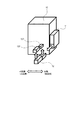
図1〜図4を用いて、本発明の実施例1に係る画像形成装置について説明する。図1は、本発明の実施の形態に係る画像形成装置の外観斜視図である。図2は、本発明の画像形成装置10の側面方向から見た概略断面図である。
[Example 1]
The image forming apparatus according to the first embodiment of the present invention will be described with reference to FIGS. 1 to 4. FIG. 1 is an external perspective view of an image forming apparatus according to an embodiment of the present invention. FIG. 2 is a schematic cross-sectional view of the
画像形成装置10では、装置内を図示していないが、周知のように、像担持体にトナー画像が形成され、記録材に転写され、定着される。すなわち、帯電器により均一に帯電された感光体ドラム(像担持体)の表面に、画像情報に応じたレーザ光が照射されて静電潜像が形成される。そして、現像器から供給されたトナー(現像剤)によって、前記静電潜像が現像され、前記感光体ドラムの表面にトナーによる画像が形成される。そして、一枚ずつ供給される記録材に対して、前記感光体ドラムに形成されたトナーによる画像が転写され、前記転写画像は定着器により記録材に定着される。
In the
図1及び図2に示すように、画像形成装置10の背面側には、装置内のエアを装置外に向けて排気する複数の風路を備えた排気ダクト11が設けられている。ここで、画像形成装置の背面側とは、オペレータ(操作者)が操作する側を画像形成装置の正面側(手前側)とした場合、この正面側(手前側)とは反対側(奥側)である。また、以下の説明で、画像形成装置の上面とは、画像形成装置の手前奥を示す矢印方向と直交する画像形成装置の高さ方向(上下方向)の上側の面である。画像形成装置の下面(底面)とは、前記画像形成装置の高さ方向の下側の面であり、前記上面とは反対側の面である。また画像形成装置の側面とは、画像形成装置の手前奥を示す矢印方向及び前記上下方向と直交する画像形成装置の幅方向(左右方向)の面である。
As shown in FIGS. 1 and 2, an
前述の画像形成装置において、画像形成時には、帯電器からのオゾンや、定着器からのVOC、トナーなどからの超微粒子(UFP)が発生している。ここで、VOCとは揮発性有機化合物のことで、ホルムアルデヒドやキシレン等のことをいう。前記排気ダクト11から、装置内のエアを装置外に向けて排気する際に、前述のオゾン/VOC/UFPなどを装置外へ排出しないようにする必要がある。そのため、画像形成装置10には、装置内のエアを排気する前に、オゾン/VOC/UFPなどを除去する複数のフィルタ13が設けられている。複数のフィルタ13は、前記排気ダクトにおいて、複数の風路のそれぞれに設けられ、前記風路を通して排気されるエアに含まれる微粒子を取り除く。
In the above-mentioned image forming apparatus, ozone from the charger, VOC from the fixing device, ultrafine particles (UFP) from toner and the like are generated at the time of image formation. Here, VOC is a volatile organic compound, such as formaldehyde and xylene. When the air inside the device is exhausted from the
本実施例では、前記排気ダクト11が備えた複数の風路として、以下の風路を例示している。すなわち、排気ダクト11は、主にオゾンやUFPを含んだエアを排気する第1の風路111と、主にVOCを含んだエアを排気する第2の風路112と、微粒子等を含まない基板周りの熱を排出する第3の風路113と、を有している。この複数の風路のうち、第1の風路111及び第2の風路112はエアが装置底面側に向かうように風路が形成され、第3の風路113はエアが装置背面側に向かうように、それぞれ形成されている。なお、排気ダクトが備えた風路の数や役目は、前述の構成に限定されるものではなく、必要に応じて適宜設定すればよい。
In this embodiment, the following air passages are illustrated as a plurality of air passages provided in the
また、装置内を冷却するための外気の取り入れ口(吸気口)は、画像形成装置10の側面、前面、底面などから行っている(不図示)。 Further, the outside air intake port (intake port) for cooling the inside of the device is provided from the side surface, the front surface, the bottom surface, or the like of the image forming device 10 (not shown).
図3及び図4を用いて、前記排気ダクトが備えた複数の風路と、各風路に設けられた複数のフィルタについて詳しく説明する。 A plurality of air passages provided in the exhaust duct and a plurality of filters provided in each air passage will be described in detail with reference to FIGS. 3 and 4.
図3(a)、図3(b)は、図2のA−A断面図である。図3(a)は、複数のフィルタ13が画像形成装置10に配置された状態の断面図であり、ダクト11内のエアの流れを示している。図3(b)は、複数のフィルタ13を画像形成装置10から取り出す時の断面図である。図4は、複数のフィルタ13を画像形成装置10から取り出す時の模式斜視図である。
3A and 3B are cross-sectional views taken along the line AA of FIG. FIG. 3A is a cross-sectional view of a state in which a plurality of
第1の風路111には、UFPやオゾンをフィルタする第1のフィルタ131が配置されている。第2の風路112には、VOCをフィルタする第2のフィルタ132が配置されている。ダクト11内には、第1の風路111と第2の風路112の間のエアを仕切る仕切り部材114(113)が配置されている。また、図4に示すように、ダクト11には、第1のフィルタ131と第2のフィルタ132を取り出し可能に収納するフィルタケース12が設けられている。フィルタケース12は、画像形成装置10に対して、画像形成装置の正面側から背面側に向かって、画像形成装置の左右方向の一方の側面側(矢印B方向)に引き出し可能に設けられている。
A
装置内の熱を効率よく排気するためには、排気抵抗が少ないほどよい。近年規制が強まっているオゾン、VOC、UFPの除去能力を向上させ、かつ、排熱効果を高めるためには、フィルタ13を大型化し、排気経路のシールを強化する必要がにある。さらに、耐久でフィルタの目詰まりが進行し、装置内の温度が異常に上昇することでの画像不良やエラーの発生を防止するためには、定期的にフィルタ13を清掃あるいは交換する必要がある。本実施例では、複数のフィルタ13を収納したフィルタケース12を、画像形成装置10の一方の側面側に引き出し可能としたことで、画像形成装置10の背面側の作業スペースを確保しなくても、複数のフィルタ13を清掃、交換する作業が容易に行える。そのため、装置の背面側の作業スペースの削減につながり、定期メンテナンスでのオペレータの負荷を低減することができる。また、複数のフィルタを同時に交換することができる。
In order to efficiently exhaust the heat in the device, the smaller the exhaust resistance, the better. In order to improve the removal capacity of ozone, VOC, and UFP, which have been tightened in recent years, and to enhance the heat exhaust effect, it is necessary to increase the size of the
さらに、本実施例では、複数のフィルタ13のうち、フィルタケース12の引き出し方向の手前側に収納されたフィルタ131は、奥側に収納されたフィルタ132に比べて、引き出し方向Bに直交する上下方向のサイズが大きい(図3のL1>L2)。そのため、フィルタケース12を画像形成装置10に取り付け時、図3(a)に示すように複数のフィルタ13と仕切り部材114との間のシールが容易に実現できる。このようにすることで、複数のフィルタを有するフィルタケース12が、風路に直交する方向に取り出し可能な構成でも、風路間のシールの確保が可能となる。
Further, in the present embodiment, among the plurality of
次に、シール部材141,142,143について、図3(a),図3(b)を用いて説明する。フィルタケース12には、ダクト11との間のシールを行うシール部材141が設けられている。ダクト11内の仕切り部材114には、第1の風路111と第2の風路112の間のシールを行うシール部材142が設けられている。ダクト11には、フィルタケース12との間のシールを行うシール部材143が設けられている。フィルタケース12をダクト11に取り付けた状態では、フィルタケース12は、シール部材141,142,143から、フィルタケース12の取り出し方向Bへの付勢力を受けている。この付勢力によりフィルタケース12が取り出し方向Bに飛び出してくることを防止するため、フィルタケース12には、ダクト11と係合するストッパ121が設けられている。ストッパ121は弾性部材でできており、フィルタケース12を取り出す際には、ストッパ121を図3(a)の上方向へ撓ませることで、ダクト11との係合を弾性力で解除可能なようにしている。このようにすることで、工具を使わずとも、ストッパ121による係合の解除を行うだけで、フィルタケース12をダクト11から取り出すことが可能となる。また、通常使用時は内部のシール性を確保しつつ、フィルタ交換時にはストッパを解除するのみでフィルタケースを交換可能となり、メンテナンス性の良い画像形成装置を提供できる。
Next, the
〔実施例2〕
図5を用いて、本発明の実施例2に係る画像形成装置について説明する。図5は、本発明の実施例2を示す画像形成装置10の概略斜視図である。
[Example 2]
The image forming apparatus according to the second embodiment of the present invention will be described with reference to FIG. FIG. 5 is a schematic perspective view of the
実施例1では、排気ダクト11を、画像形成装置10の背面側の外部に突出するように設けた構成を例示した。この構成によれば、排気ダクトの第1の風路及び第2の風路を通して排気されるエアを、画像形成装置の下面側に向けることができる。これに対し、本実施例では、図5に示すように、排気ダクト11を、画像形成装置10の内部に設けている。ここでは画像形成装置10の排気口は、画像形成装置10の背面に配置されている。
In the first embodiment, the configuration in which the
そして、複数のフィルタ13を有するフィルタケース12を、前述した実施例1と同様に、画像形成装置10の一方の側面側に引き出し可能に設けている。フィルタケース12内に配置される2つのフィルタ131,132のサイズは、ダクト11が備える複数の風路のうちの断面積方向(引き出し方向に直交する方向)のサイズが大きい方がフィルタケース12の引き出し方向の手前側に配置されている。
Then, a
このように、フィルタ13の風路方向の厚みが同じでも、風路の断面積の大きい方のフィルタをフィルタケース12の引き出し方向の手前側に配置することで、フィルタケース12の小型化が可能となり、また、風路間のシールも容易になる。その結果、フィルタ13のメンテナンス時の作業スペースおよび画像形成装置10の設置スペースの省スペース化を実現することができる。
In this way, even if the thickness of the
〔実施例3〕
図6を用いて、本発明の実施例3に係る画像形成装置10について説明する。図6は、本発明の実施例3を示す画像形成装置10の概略斜視図である。
[Example 3]
The
実施例1では、排気ダクト11を、画像形成装置10の背面側の外部に突出するように設けた構成を例示した。この構成によれば、排気ダクトの第1の風路及び第2の風路を通して排気されるエアを、画像形成装置の下面側に向けることができる。これに対し、本実施例では、図6に示すように、排気ダクト11を、画像形成装置10の内部に設けている。ここでは画像形成装置10の排気口は、画像形成装置10の背面に配置されている。
In the first embodiment, the configuration in which the
また実施例1では、複数のフィルタ13を有するフィルタケース12を、画像形成装置10に対して一方の側面側に引き出し可能に設けている。これに対し、本実施例では、図6に示すように、複数のフィルタ13を有するフィルタケース12を、画像形成装置10に対して、画像形成装置の上下方向(高さ方向)の上面側に引き出し可能に設けている。
Further, in the first embodiment, the
このように構成しても、実施例1,2と同様に、画像形成装置からフィルタケース12を取り出す際に、画像形成装置10の作業スペースを増やすことなく、複数のフィルタ13の清掃、交換の作業を行うことができる。
Even with this configuration, as in the first and second embodiments, when the
〔実施例4〕
図7〜図12を用いて、本発明の実施例4に係る画像形成装置10について説明する。図7は、本発明の第4の実施例を示す画像形成装置10の側面図である。
[Example 4]
The
前述した実施例1では、フィルタケース12を、画像形成装置10に対して、画像形成装置10の一方の側面側に引き出し可能に設けた構成を例示した。すなわち、フィルタケース12の取り出し時のアクセス面221を、画像形成装置の一方の側面に設けた構成を例示した。
In Example 1 described above, a configuration in which the
本実施例では、フィルタ以外に画像形成装置に対して着脱可能なメンテナンス部品を、画像形成装置に対して、フィルタケースが引き出し可能な画像形成装置の一方の側面側から着脱可能に設けている。すなわち、フィルタ以外の他のメンテナンス部品へのアクセス面を、フィルタケース12の取り出し時のアクセス面221が設けられた、画像形成装置の一方の側面に集約して配置した構成としている。
In this embodiment, in addition to the filter, maintenance parts that can be attached to and detached from the image forming apparatus are provided to the image forming apparatus so that they can be attached to and detached from one side surface side of the image forming apparatus from which the filter case can be pulled out. That is, the access surfaces for maintenance parts other than the filter are centrally arranged on one side surface of the image forming apparatus provided with the
ここでは、フィルタ以外に画像形成装置に対して着脱可能なメンテナンス部品として、大容量記憶装置、電気基板、及び、回収トナーボトルを例示している。本実施例では、大容量記憶装置へのアクセス面222と、電気基板へのアクセス面223と、回収トナーボトル交換時のアクセス面224を、フィルタケース12の取り出し時のアクセス面221が設けられた画像形成装置の一方の側面に集約して配置している。さらに、記録対象である記録材を画像形成装置の装置本体に供給する着脱可能な保持部材236の取り付け時のアクセス面225を、フィルタケース12の取り出し時のアクセス面221が設けられた、画像形成装置の一方の側面に配置している。このように画像形成装置の一方の側面にメンテナンス部品へのアクセス面を集約して配置することで、オペレータにメンテナンス部品へのアクセス面の位置をわかりやすくする。
Here, a large-capacity storage device, an electric board, and a recovered toner bottle are exemplified as maintenance parts that can be attached to and detached from the image forming apparatus in addition to the filter. In this embodiment, an access surface 222 for the large-capacity storage device, an access surface 223 for the electric board, an access surface 224 for exchanging the recovered toner bottle, and an
また、フィルタケース12の取り出し時のアクセス面221は、前記一方の側面において、他のメンテナンス部品よりも装置奥側(背面側)に配置されている。また、大容量記憶装置へのアクセス面222と電気基板へのアクセス面223と回収トナーボトル交換時のアクセス面224は、前記一方の側面において、前記フィルタケースへのアクセス面221よりも装置手前側に配置されている。また、トナーボトル交換時のアクセス面224は、大容量記憶装置へのアクセス面222と電気基板へのアクセス面223よりも装置下側に配置されている。さらに、保持部材236の取り付け面225は、前記一方の側面において、前記アクセス面221〜224よりも装置手前側に配置されている。
Further, the
このようにフィルタケースの取り出し時のアクセス面221を装置奥側に配置することで、エアの排気口をユーザから離れた位置に配置することができる。また、回収トナーボトル交換時のアクセス面224を大容量記憶装置へのアクセス面222と電気基板へのアクセス面223よりも下側に配置することで、他のメンテナンス部品に比べて重量の大きいメンテナンス部品を下側に配置することができ、ユーザーの負荷を軽減できる。また、保持部材236の取り付け面225を画像形成装置の手前側とすることで、アクセス頻度の高い記録材供給作業面をオペレータに近い位置に配置でき、オペレータの負荷を軽減できる。
By arranging the
大容量記憶装置と電気基板のアクセスの詳細構成について、図8を用いて説明する。図8は、図7のB−B断面図である。 The detailed configuration of the access between the large-capacity storage device and the electric board will be described with reference to FIG. FIG. 8 is a cross-sectional view taken along the line BB of FIG.
メンテナンス部品のアクセス面が集約される画像形成装置の一方の側面には、大容量記憶装置と電気基板を覆う樹脂等を材料としたカバー201,202が配置されている。 On one side surface of the image forming apparatus where the access surfaces of maintenance parts are integrated, covers 201 and 202 made of a large-capacity storage device and a resin or the like covering an electric substrate are arranged.
このカバーは2つのカバー201,202によって構成されている。内カバー201は電気基板を収納し覆う役割を果たす基板収納部材203と1点以上ねじ締結により固定される。内カバー201は、上方向に突設された1本以上の軸部201aを有している。外カバー202は前記内カバー201が有する軸部201aと嵌合する穴202aを有している。内カバー201の軸部201aに外カバー202の穴202aを嵌めることにより、内カバー201と外カバー202が接続され、外カバー202は内カバー201の軸部201aを中心に回転でき、開閉が可能となる。また、外カバー202は前記軸部201aより画像形成装置の手前側に配置された握手部202bを有している。
This cover is composed of two
内カバー201と外カバー202から成るカバーの内側には、金属等を材料としたカバー部材が配置されている。この金属等を材料としたカバー部材は2つのカバー部材で構成されている。一方のカバー部材は、電気基板を収納し覆う役割を果たす基板収納部材203であり、上側に配置されている。他方のカバー部材は、大容量記憶装置部を覆う役割を果たす蓋部材204であり、下側に配置されている。内カバー201は、軸部201aを中心に外カバー202を開いた際に、アクセス集約面側(画像形成装置の一方の側面側)から蓋部材204にアクセス可能となる開口部201bを有している。
Inside the cover composed of the
蓋部材204でアクセス集約面側を覆われた大容量記憶装置は、筐体形状の筐体部材205に収納されている。筐体部材205は、画像形成装置の手前奥方向に貫通する1つ以上の穴205aを有している。この筐体部材205が有する穴205aは、筐体部材205の下側でかつメンテナンス部品へのアクセス面が集約された画像形成装置の一方の側面側に設けられている。蓋部材204は、大容量記憶装置が収納される筐体形状の筐体部材205に設けられた穴205aと同一軸上に配置された雌ねじ部204aを有している。軸部材206は、筐体部材205に設けられた穴205aと嵌合する軸部と、蓋部材204に設けられた雌ねじ部204aと螺合する雄ねじ部を有している。蓋部材204と筐体部材205は軸部材206により接続される。蓋部材204は軸部材206の軸中心に開閉可能であり、前記雌ねじ部より上側にオペレータが開閉するための握手部204bが配置されている。大容量記憶装置を覆う役割を果たす開閉可能な蓋部材204を開いて内側に、大容量記憶装置と1か所以上ねじ締結により接続された収納部材207が配置されている。収納部材207は、アクセス面が集約された画像形成装置の一方の側面側で、且つ収納部材207の上側位置に画像形成装置の手前奥方向に貫通する1か所以上の穴を有している。把手部材208は、収納部材207に設けられた前記穴と同一直線上に穴を有している。収納部材207と把手部材208は共通する1つ以上の嵌合軸部材209により接続され、把手部材208は嵌合軸部材209を中心に回転可能であり、かつ把手の役割を担う。
The large-capacity storage device whose access aggregation surface side is covered with the
また、大容量記憶装置が画像形成装置の一方の側面側から抜き差し可能となるよう、前記筐体部材205の内部の1面以上(ここでは上下面2面)に大容量記憶装置を抜き差し方向に誘導するための抜き差し方向と平行なガイド部材210を有する。ガイド部材210を図8のC−C断面図である図9に示す。このようなガイド部材210を設けることで、オペレータは外カバー202を開き、蓋部材204を開き、把手部材208を引き出すことにより、図10に示すように大容量記憶装置を画像形成装置の一方の側面側から抜き差しすることができる。
Further, in order to enable the large-capacity storage device to be inserted and removed from one side surface side of the image forming device, the large-capacity storage device is inserted and removed from one or more surfaces (here, two upper and lower surfaces) inside the
電気基板を収納し覆う役割を果たす基板収納部材203は、大容量記憶装置を覆う役割を果たす蓋部材204の上側に配置されている。基板収納部材203は、大容量記憶装置が収納される筐体形状の筐体部材205と1か所以上ねじ締結により接続され、メンテナンス部品へのアクセス面が集約された画像形成装置の一方の側面側に把手229が配置されている。電気基板を収納し覆う役割を果たす基板収納部材203が画像形成装置の一方の側面側から抜き差し可能となるよう、基板収納部材203を抜き差し方向に誘導するためのガイド部材211が、画像形成装置の内部に設けられている。ガイド部材211を図9に示す。このようなガイド部材211を設けることで、オペレータは内カバー201と基板収納部材203のねじ締結を外して内カバー201と外カバー202を取り外し、基板収納部材203を画像形成装置から引き出すことができる。すなわち、図11に示すように電気基板を画像形成装置の一方の側面側から抜き差しすることができる。
The
また、図7に示すように、メンテナンス部品のアクセス面が集約される画像形成装置の一方の側面には、回収トナーボトルを覆う樹脂等を材料としたカバー212が配置されている。カバー212は、大容量記憶装置へのアクセス面222と電気基板へのアクセス面223より下側に配置されている。 Further, as shown in FIG. 7, a cover 212 made of a resin or the like covering the recovered toner bottle is arranged on one side surface of the image forming apparatus where the access surfaces of the maintenance parts are integrated. The cover 212 is arranged below the access surface 222 to the large-capacity storage device and the access surface 223 to the electric board.
回収トナーボトルを覆うカバー212は、画像形成装置と1か所以上ねじ230の締結により固定される。オペレータは画像形成装置とのねじ230の締結を外すことにより回収トナーボトルへアクセスすることができる。
The cover 212 that covers the recovered toner bottle is fixed to the image forming apparatus by fastening one or
さらに、図7に示すように、メンテナンス部品のアクセス面が集約される画像形成装置の一方の側面には、記録対象である記録材を画像形成装置の装置本体に供給する着脱可能な保持部材236が配置されている。保持部材236は、取り付け時のアクセス面225が前記アクセス面221〜224よりも画像形成装置の手前側に配置されている。
Further, as shown in FIG. 7, on one side surface of the image forming apparatus where the access surfaces of maintenance parts are integrated, a removable holding member 236 that supplies a recording material to be recorded to the apparatus main body of the image forming apparatus. Is placed. The
画像記録対象である記録材を前記装置本体に供給する着脱可能な保持部材236は、図12に示すように奥側に筒形状の支持穴236aを上下2か所に有している。画像形成装置10は、記録材を前記装置本体に供給する着脱可能な保持部材236に設けられた筒形状の支持穴236aと同一軸上に、筒形状の支持穴10aを上下2か所に有している。画像形成装置10が有する上下各々の筒形状の支持穴10aは、保持部材236が有する筒形状の支持穴236aより上下各々が下側に設けられ、保持部材236の重量の一部を受ける。
As shown in FIG. 12, the removable holding member 236 that supplies the recording material to be image-recorded to the main body of the apparatus has two
画像形成装置10と保持部材236の両者の筒形状の支持穴10a,236aは共通の軸部材233により嵌合接続される。軸部材233はL字型形状を持つため、筒形状の支持穴への挿入時にすり抜けることが無い。また、軸部材233は画像形成装置10と保持部材236の支持穴からオペレータ自身が手作業で引き抜くことができる軸直径寸法等を持つ。また、図7に示すように保持部材236はオペレータが開閉するための把手234が前記軸部材233より手前に配置されている。これにより、保持部材236は軸部材233を中心に回転し開閉できる。
The
このような構成とすることで、オペレータは保持部材236を開き、軸部材233を取り外すことにより、画像記録対象である記録材を前記装置本体に供給する保持部材236を画像形成装置から取り外すことができる。
With such a configuration, the operator can open the holding member 236 and remove the
上述したように、本実施例では、他のメンテナンス部品へのアクセス面を、フィルタケース12の取り出し時のアクセス面221が設けられた画像形成装置の一方の側面に集約して配置した構成としている。これにより、他のメンテナンス部品についても、装置の背面側に作業スペースを確保しなくても、複数のフィルタと同様に交換する作業が容易に行える。そのため、装置の背面側の作業スペースの削減につながり、定期メンテナンスでのオペレータの負荷を低減することができる。
As described above, in the present embodiment, the access surfaces for other maintenance parts are centrally arranged on one side surface of the image forming apparatus provided with the
なお、前述した実施例で説明したフィルタ以外の他のメンテナンス部品は、例示であって、これらに限定されるものではない。 It should be noted that the maintenance parts other than the filter described in the above-described embodiment are examples and are not limited thereto.
また、前述した実施例において、フィルタケースに収納される複数のフィルタのうち、交換頻度の高いフィルタを、フィルタケースの引き出し方向の手前側に収納するようにしてもよい。これにより、フィルタの清掃・交換作業が、より容易に行える。 Further, in the above-described embodiment, among the plurality of filters stored in the filter case, the filter having a high replacement frequency may be stored on the front side in the pull-out direction of the filter case. This makes it easier to clean and replace the filter.
10 …画像形成装置
10a …支持穴
11 …ダクト
12 …フィルタケース
13 …フィルタ
111 …第1の風路
112 …第2の風路
113 …第3の風路
114 …仕切り部材
121 …ストッパ
131 …第1のフィルタ
132 …第2のフィルタ
141,142,143 …シール部材
201 …内カバー
202 …外カバー
203 …基板収納部材
204 …蓋部材
205 …筐体部材
207 …収納部材
210,211 …ガイド部材
212 …カバー
236 …保持部材
10 ...
Claims (4)
前記画像形成装置の機内の空気を機外に排気する第1の排気ダクトと、
前記画像形成装置の機内の空気を機外に排気する第2の排気ダクトと、
前記第1の排気ダクト内において、オゾンを捕集する第1のフィルタと、
前記第2の排気ダクト内において、VOCを捕集する第2のフィルタと、
前記第1のフィルタと前記第2のフィルタとを有し、前記画像形成装置の横から引き出されるフィルタケースであって、前記第1の排気ダクトと前記第2の排気ダクトの途中から引き出される前記フィルタケースと、を有し、
前記第1のフィルタと前記第2のフィルタとは、前記フィルタケースが前記画像形成装置に装着された状態において、前記画像形成装置の横方向に並んでおり、
前記フィルタケースは、
前記フィルタケースが引き出される方向において前記第1のフィルタよりも下流に設けられ、前記フィルタケースが前記画像形成装置に装着された状態において前記第1の排気ダクトの一部を構成する第1の壁部と、
前記第1のフィルタと前記第2のフィルタとの間に設けられ、前記フィルタケースが前記画像形成装置に装着された状態において前記第1の排気ダクトの一部を構成する第2の壁部と、を備え、
鉛直方向における前記第1のフィルタの幅は鉛直方向における前記第2のフィルタの幅よりも厚く、前記第1の壁部の高さは前記第2の壁部の高さよりも高いことを特徴とする画像形成装置。 It is an image forming device
A first exhaust duct that exhausts the air inside the machine of the image forming apparatus to the outside of the machine,
A second exhaust duct that exhausts the air inside the machine of the image forming apparatus to the outside of the machine,
In the first exhaust duct, the first filter that collects ozone and
In the second exhaust duct, a second filter that collects VOCs and
And a second filter and the first filter, a filter case drawn from the side of the image forming apparatus, said drawn from the middle of the first exhaust duct and the second exhaust duct With a filter case,
The first filter and the second filter are arranged in the lateral direction of the image forming apparatus in a state where the filter case is attached to the image forming apparatus.
The filter case is
A first wall provided downstream of the first filter in the direction in which the filter case is pulled out and forming a part of the first exhaust duct when the filter case is attached to the image forming apparatus. Department and
A second wall portion provided between the first filter and the second filter and forming a part of the first exhaust duct when the filter case is attached to the image forming apparatus. , With
The width of the first filter in the vertical direction is thicker than the width of the second filter in the vertical direction, and the height of the first wall portion is higher than the height of the second wall portion. Image forming device.
前記仕切りに設けられ、前記仕切りと前記第2の壁部とに挟まれて弾性変形することにより前記第1の排気ダクトと前記第2の排気ダクトとの間のシールを確保するシール部材と、を備えることを特徴とする請求項1に記載の画像形成装置。 A partition which said first exhaust duct and constitutes a part of the second exhaust duct, separates the air passage and the air passage of the first exhaust duct and the second exhaust duct,
A seal member provided in the partition, which is sandwiched between the partition and the second wall portion and elastically deformed to secure a seal between the first exhaust duct and the second exhaust duct. The image forming apparatus according to claim 1, further comprising.
前記大容量記憶装置は、前記画像形成装置に対して前記フィルタケースが引き出される側と同じ側から前記画像形成装置に対して引き出し可能であって、
前記フィルタケースは前記大容量記憶装置よりも前記画像形成装置の奥に装着されることを特徴とする請求項1または請求項2に記載の画像形成装置。 It has a large-capacity storage device that can be attached to and detached from the image forming device.
The large-capacity storage device can be pulled out from the same side as the side from which the filter case is pulled out from the image forming device to the image forming device.
The image forming apparatus according to claim 1 or 2 , wherein the filter case is mounted deeper than the large-capacity storage device.
Priority Applications (5)
| Application Number | Priority Date | Filing Date | Title |
|---|---|---|---|
| JP2016122299A JP6910761B2 (en) | 2016-06-21 | 2016-06-21 | Image forming device |
| US15/623,901 US10025270B2 (en) | 2016-06-21 | 2017-06-15 | Image forming apparatus |
| US16/010,879 US10162306B2 (en) | 2016-06-21 | 2018-06-18 | Image forming apparatus |
| JP2021112489A JP2021165859A (en) | 2016-06-21 | 2021-07-07 | Image formation apparatus |
| JP2023032568A JP2023071880A (en) | 2016-06-21 | 2023-03-03 | Image formation apparatus |
Applications Claiming Priority (1)
| Application Number | Priority Date | Filing Date | Title |
|---|---|---|---|
| JP2016122299A JP6910761B2 (en) | 2016-06-21 | 2016-06-21 | Image forming device |
Related Child Applications (1)
| Application Number | Title | Priority Date | Filing Date |
|---|---|---|---|
| JP2021112489A Division JP2021165859A (en) | 2016-06-21 | 2021-07-07 | Image formation apparatus |
Publications (3)
| Publication Number | Publication Date |
|---|---|
| JP2017227693A JP2017227693A (en) | 2017-12-28 |
| JP2017227693A5 JP2017227693A5 (en) | 2019-07-25 |
| JP6910761B2 true JP6910761B2 (en) | 2021-07-28 |
Family
ID=60659477
Family Applications (3)
| Application Number | Title | Priority Date | Filing Date |
|---|---|---|---|
| JP2016122299A Active JP6910761B2 (en) | 2016-06-21 | 2016-06-21 | Image forming device |
| JP2021112489A Pending JP2021165859A (en) | 2016-06-21 | 2021-07-07 | Image formation apparatus |
| JP2023032568A Pending JP2023071880A (en) | 2016-06-21 | 2023-03-03 | Image formation apparatus |
Family Applications After (2)
| Application Number | Title | Priority Date | Filing Date |
|---|---|---|---|
| JP2021112489A Pending JP2021165859A (en) | 2016-06-21 | 2021-07-07 | Image formation apparatus |
| JP2023032568A Pending JP2023071880A (en) | 2016-06-21 | 2023-03-03 | Image formation apparatus |
Country Status (2)
| Country | Link |
|---|---|
| US (2) | US10025270B2 (en) |
| JP (3) | JP6910761B2 (en) |
Families Citing this family (9)
| Publication number | Priority date | Publication date | Assignee | Title |
|---|---|---|---|---|
| JP2020016674A (en) * | 2018-07-23 | 2020-01-30 | 京セラドキュメントソリューションズ株式会社 | Image forming apparatus |
| EP3835875A4 (en) * | 2018-08-09 | 2022-04-20 | Canon Kabushiki Kaisha | Image-forming device |
| JP7071242B2 (en) * | 2018-08-09 | 2022-05-18 | キヤノン株式会社 | Image forming device |
| JP7071243B2 (en) * | 2018-08-09 | 2022-05-18 | キヤノン株式会社 | Image forming device |
| JP7110027B2 (en) * | 2018-08-09 | 2022-08-01 | キヤノン株式会社 | image forming device |
| JP2021179580A (en) | 2020-05-15 | 2021-11-18 | キヤノン株式会社 | Image forming apparatus |
| JP2021179581A (en) | 2020-05-15 | 2021-11-18 | キヤノン株式会社 | Image forming apparatus |
| JP2021179582A (en) | 2020-05-15 | 2021-11-18 | キヤノン株式会社 | Frame body of image forming apparatus and image forming apparatus |
| JP2022094203A (en) * | 2020-12-14 | 2022-06-24 | キヤノン株式会社 | Image forming apparatus |
Family Cites Families (32)
| Publication number | Priority date | Publication date | Assignee | Title |
|---|---|---|---|---|
| JPS496850U (en) * | 1972-04-19 | 1974-01-21 | ||
| JP2613145B2 (en) * | 1991-10-17 | 1997-05-21 | 大吉 末松 | Rainwater penetration structure of waterway |
| JPH05223308A (en) * | 1992-02-14 | 1993-08-31 | Toshiba Corp | Ventilation fan with heat exchanger |
| JPH0822225A (en) * | 1994-07-07 | 1996-01-23 | Ricoh Co Ltd | Image forming device |
| JPH09160450A (en) * | 1995-12-04 | 1997-06-20 | Ricoh Co Ltd | Blower for image forming device |
| JPH10198238A (en) | 1996-12-27 | 1998-07-31 | Konica Corp | Image forming device |
| JP2000330435A (en) * | 1999-05-21 | 2000-11-30 | Ricoh Co Ltd | Exhaust treating unit of image forming device |
| US6297950B1 (en) * | 1999-06-17 | 2001-10-02 | Inclose Design, Inc. | Filter assembly for a memory storage device cooler |
| JP2002229400A (en) * | 2001-02-05 | 2002-08-14 | Ricoh Co Ltd | Copying device |
| JP2002268481A (en) * | 2001-03-09 | 2002-09-18 | Ricoh Co Ltd | Filter attaching mechanism for copying machine |
| JP3893321B2 (en) * | 2002-05-24 | 2007-03-14 | キヤノン株式会社 | Image forming apparatus |
| JP2004045573A (en) * | 2002-07-09 | 2004-02-12 | Canon Inc | Image forming apparatus |
| DE60316176T2 (en) * | 2002-10-28 | 2008-05-29 | Donaldson Co., Inc., Minneapolis | AIR FILTER; REPLACEABLE FILTER CARTRIDGE; AND METHOD |
| JP4217509B2 (en) | 2003-03-10 | 2009-02-04 | 株式会社リコー | Exhaust port silencer for image forming apparatus and image forming apparatus using the same |
| JP2005141258A (en) * | 2005-02-07 | 2005-06-02 | Fuji Xerox Co Ltd | Image forming apparatus |
| JP4636955B2 (en) * | 2005-07-06 | 2011-02-23 | キヤノン株式会社 | Air processing apparatus and image forming system |
| KR100793953B1 (en) * | 2005-11-18 | 2008-01-16 | 삼성전자주식회사 | Cooling apparatus and image forming device having the same |
| US7477860B2 (en) * | 2006-08-25 | 2009-01-13 | Kyocera Mita Corporation | Image forming apparatus with an air channel that communicates with a handle for a sheet cassette |
| JP5140544B2 (en) | 2008-10-16 | 2013-02-06 | 京セラドキュメントソリューションズ株式会社 | Exhaust device and image forming apparatus equipped with the same |
| JP4969630B2 (en) * | 2009-10-13 | 2012-07-04 | シャープ株式会社 | Image forming apparatus |
| JP5402568B2 (en) * | 2009-11-25 | 2014-01-29 | 富士ゼロックス株式会社 | Image forming apparatus |
| JP5017388B2 (en) * | 2010-01-29 | 2012-09-05 | シャープ株式会社 | Image forming apparatus |
| CN102236280A (en) * | 2010-04-21 | 2011-11-09 | 株式会社东芝 | Image forming apparatus for changing exhaust air direction |
| JP5790060B2 (en) * | 2011-03-25 | 2015-10-07 | 富士ゼロックス株式会社 | Image forming apparatus |
| JP5834764B2 (en) * | 2011-10-21 | 2015-12-24 | 富士ゼロックス株式会社 | Image forming apparatus and collection apparatus |
| JP2015072451A (en) * | 2013-09-06 | 2015-04-16 | 株式会社リコー | Cooling apparatus and image forming apparatus |
| JP5862977B2 (en) * | 2013-10-24 | 2016-02-16 | コニカミノルタ株式会社 | Exhaust device and image forming apparatus having the same |
| JP6319650B2 (en) * | 2014-02-24 | 2018-05-09 | 株式会社リコー | Exhaust flow path unit and image forming apparatus |
| JP2016049470A (en) * | 2014-08-28 | 2016-04-11 | 清水建設株式会社 | Dust collection unit |
| US20160296870A1 (en) * | 2015-04-13 | 2016-10-13 | Electrolux Home Products, Inc. | Vent filter and appliance utilizing such a filter |
| JP2016206397A (en) * | 2015-04-22 | 2016-12-08 | 株式会社リコー | Duct and image forming apparatus |
| JP2017207709A (en) * | 2016-05-20 | 2017-11-24 | キヤノン株式会社 | Image forming apparatus |
-
2016
- 2016-06-21 JP JP2016122299A patent/JP6910761B2/en active Active
-
2017
- 2017-06-15 US US15/623,901 patent/US10025270B2/en active Active
-
2018
- 2018-06-18 US US16/010,879 patent/US10162306B2/en active Active
-
2021
- 2021-07-07 JP JP2021112489A patent/JP2021165859A/en active Pending
-
2023
- 2023-03-03 JP JP2023032568A patent/JP2023071880A/en active Pending
Also Published As
| Publication number | Publication date |
|---|---|
| US20180299827A1 (en) | 2018-10-18 |
| JP2023071880A (en) | 2023-05-23 |
| US10025270B2 (en) | 2018-07-17 |
| JP2017227693A (en) | 2017-12-28 |
| JP2021165859A (en) | 2021-10-14 |
| US20170364027A1 (en) | 2017-12-21 |
| US10162306B2 (en) | 2018-12-25 |
Similar Documents
| Publication | Publication Date | Title |
|---|---|---|
| JP6910761B2 (en) | Image forming device | |
| JP5153260B2 (en) | Image forming apparatus | |
| EP2093623B1 (en) | Cover member, developing cartridge and developing unit for image forming apparatus | |
| JP4730087B2 (en) | Image forming apparatus | |
| TWI503236B (en) | Outer type toner dust filter assembly for office appliance | |
| JP2010276961A (en) | Constituting unit for image forming apparatus and developing unit | |
| JP2017107012A (en) | Image formation device | |
| JP5834764B2 (en) | Image forming apparatus and collection apparatus | |
| JP2015232695A (en) | Image forming apparatus | |
| JP5810034B2 (en) | Image forming apparatus | |
| JP5219567B2 (en) | Dust collector | |
| JP6610870B2 (en) | Image forming apparatus | |
| JP6153391B2 (en) | Image forming apparatus | |
| JP2008292514A (en) | Waste toner recovery container | |
| KR100963904B1 (en) | Cover member, developing cartridge and developing unit for image forming apparatus | |
| JP2010276964A (en) | Image forming apparatus, tandem type photoreceptor unit and developing cartridge | |
| JP5332768B2 (en) | Image forming apparatus | |
| JP6844652B2 (en) | Waste toner storage container and image forming device | |
| JP2019113760A (en) | Image forming apparatus | |
| JP6020898B2 (en) | Paper discharge device | |
| JP2020160271A (en) | Powder collection device and powder processing apparatus using the same | |
| JPH09325666A (en) | Image forming device | |
| JP2020016674A (en) | Image forming apparatus | |
| JPH02110584A (en) | Image forming device | |
| KR100881278B1 (en) | Dirst collection apparatus for copier toner |
Legal Events
| Date | Code | Title | Description |
|---|---|---|---|
| A521 | Request for written amendment filed |
Free format text: JAPANESE INTERMEDIATE CODE: A523 Effective date: 20190617 |
|
| A621 | Written request for application examination |
Free format text: JAPANESE INTERMEDIATE CODE: A621 Effective date: 20190617 |
|
| A977 | Report on retrieval |
Free format text: JAPANESE INTERMEDIATE CODE: A971007 Effective date: 20200423 |
|
| A131 | Notification of reasons for refusal |
Free format text: JAPANESE INTERMEDIATE CODE: A131 Effective date: 20200602 |
|
| A521 | Request for written amendment filed |
Free format text: JAPANESE INTERMEDIATE CODE: A523 Effective date: 20200729 |
|
| A131 | Notification of reasons for refusal |
Free format text: JAPANESE INTERMEDIATE CODE: A131 Effective date: 20210105 |
|
| A521 | Request for written amendment filed |
Free format text: JAPANESE INTERMEDIATE CODE: A523 Effective date: 20210308 |
|
| TRDD | Decision of grant or rejection written | ||
| A01 | Written decision to grant a patent or to grant a registration (utility model) |
Free format text: JAPANESE INTERMEDIATE CODE: A01 Effective date: 20210608 |
|
| A61 | First payment of annual fees (during grant procedure) |
Free format text: JAPANESE INTERMEDIATE CODE: A61 Effective date: 20210707 |
|
| R151 | Written notification of patent or utility model registration |
Ref document number: 6910761 Country of ref document: JP Free format text: JAPANESE INTERMEDIATE CODE: R151 |