EP3835707A1 - Support pour arme individuelle - Google Patents
Support pour arme individuelle Download PDFInfo
- Publication number
- EP3835707A1 EP3835707A1 EP20209122.9A EP20209122A EP3835707A1 EP 3835707 A1 EP3835707 A1 EP 3835707A1 EP 20209122 A EP20209122 A EP 20209122A EP 3835707 A1 EP3835707 A1 EP 3835707A1
- Authority
- EP
- European Patent Office
- Prior art keywords
- weapon
- support
- intended
- stop
- caliper
- Prior art date
- Legal status (The legal status is an assumption and is not a legal conclusion. Google has not performed a legal analysis and makes no representation as to the accuracy of the status listed.)
- Granted
Links
Images


Classifications
-
- F—MECHANICAL ENGINEERING; LIGHTING; HEATING; WEAPONS; BLASTING
- F41—WEAPONS
- F41A—FUNCTIONAL FEATURES OR DETAILS COMMON TO BOTH SMALLARMS AND ORDNANCE, e.g. CANNONS; MOUNTINGS FOR SMALLARMS OR ORDNANCE
- F41A23/00—Gun mountings, e.g. on vehicles; Disposition of guns on vehicles
- F41A23/02—Mountings without wheels
- F41A23/18—Rests for supporting smallarms in non-shooting position
-
- B—PERFORMING OPERATIONS; TRANSPORTING
- B60—VEHICLES IN GENERAL
- B60R—VEHICLES, VEHICLE FITTINGS, OR VEHICLE PARTS, NOT OTHERWISE PROVIDED FOR
- B60R7/00—Stowing or holding appliances inside vehicle primarily intended for personal property smaller than suit-cases, e.g. travelling articles, or maps
- B60R7/08—Disposition of racks, clips, holders, containers or the like for supporting specific articles
- B60R7/14—Disposition of racks, clips, holders, containers or the like for supporting specific articles for supporting weapons
-
- F—MECHANICAL ENGINEERING; LIGHTING; HEATING; WEAPONS; BLASTING
- F41—WEAPONS
- F41B—WEAPONS FOR PROJECTING MISSILES WITHOUT USE OF EXPLOSIVE OR COMBUSTIBLE PROPELLANT CHARGE; WEAPONS NOT OTHERWISE PROVIDED FOR
- F41B5/00—Bows; Crossbows
- F41B5/14—Details of bows; Accessories for arc shooting
- F41B5/1442—Accessories for arc or bow shooting
- F41B5/1453—Stands, rests or racks for bows
Definitions
- the technical field of the invention is that of supports for individual guns of the rifle type which are carried on board military vehicles.
- the patent US2018 / 0170268 describes a support for a small arms comprising a sabot pivoting about a transverse axis.
- the shoe is intended to receive the rear of the butt of a weapon.
- the sabot is tilted forward around the axis, the user can place the weapon in the sabot.
- the barrel of the weapon is brought into an electrically lockable collar which then holds the weapon vertically along a mast.
- the user must unlock the collar and tilt the weapon forward.
- the patent US3700147 discloses a holder for small arms comprising a shoe intended to contain the butt of the weapon. This shoe is mounted to pivot relative to a support vis-à-vis which it is returned to position by elastic means. A stop of indefinite shape makes it possible to stop the pivotal movement of the weapon driven by the sabot.
- the patent application US2003 / 042283 describes a support for a tool, a bow or a gun, a support comprising a pair of brackets which are each intended to receive a branch of the tool or of the bow.
- the brackets are mounted to pivot relative to a support to which they are each connected by elastic means exerting a pivoting torque about an axis perpendicular to the support.
- None of these devices ensures a simple and reliable maintenance of a weapon on a support which can adopt several orientations.
- the invention proposes a support of simple and reliable design, support which can moreover be implemented with one hand and which can be positioned in different orientations, in particular on a plane close to the horizontal.
- the subject of the invention is a support for a small weapon which is intended to be made integral with a surface
- support comprising, on the one hand, a stirrup comprising at least two bearing zones between which the weapon is intended to be placed, the caliper which is intended to be made integral with the surface by means of a pivot axis, the support comprising an elastic return means which applies a torque causing the caliper to pivot relative to the surface and around the axis of pivot, the bearing zones then being able to transmit the torque to the weapon
- support comprising on the other hand a stop intended to be made integral with the surface and placed at a distance from the caliper, which stop can stop the pivoting of the weapon when subjected to the torque transmitted by the support zones of the caliper, support characterized in that the stop includes a lug positioned so as to oppose the withdrawal of the weapon by translation in a direction parallel to the pivot axis, the stopper and its lug forming a hook which is oriented in such a way that the weapon is
- each support zone of the caliper may also include a lug positioned so as to oppose the withdrawal of the weapon by translation in a direction parallel to the pivot axis.
- the support may include a plate secured to the pivoting bracket, the plate comprising a stopper intended to interfere with a butt of the weapon in order to stop its longitudinal sliding in the direction of the stopper.
- the plate may include a shoe forming the stopper, shoe delimiting a housing which will be intended to receive the butt of the weapon in order to limit the transverse movements of the latter.
- the support may include a fixed plate which will be intended to be made integral with the surface, the plate comprising a bearing face which will be intended to interfere with a butt of the weapon in order to stop its longitudinal sliding by direction of the bearing face.
- the fixed plate may include a rim at the level of its bearing face, which rim will be intended to interfere with the butt of the weapon in order to block its movements in a direction parallel to the pivot axis.
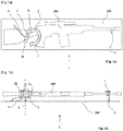
- a support 1 for a long individual weapon 100, of the automatic rifle type is fixed to a surface 200 which is here horizontal.
- the surface may for example be an external surface of a vehicle in the vicinity of a manhole.
- the support 1 then makes it possible to position the weapon close to an observer taking out his torso through the manhole.
- the support 1 comprises a bracket 2 which comprises two uprights 3a and 3b, which are here rods oriented perpendicular to the surface 200, and which form support zones 3a and 3b, located on either side of the weapon. 100, preferably at the level of the butt.
- a pivot pin 4 which secures the stirrup 2 with the surface 200, thus allowing the stirrup 2 to be able to pivot relative to the surface 200.
- the axis pivot 4 is perpendicular to the surface 200.
- the support 1 also comprises an elastic return means 5 which is fixed so as to exert a force between the caliper 2 and the surface 200 so as to produce a pivoting torque C around the pivot axis 4.
- This torque C tends to cause the weapon 100 to pivot around the pivot axis 4 but the latter is stopped in rotation in the direction of the torque C by a stop 6 of the support 1 which is located at a distance from the bracket 2 and which interferes with a front part of the weapon 100, preferably the barrel.
- the weapon is thus maintained in a plane P which is parallel to the surface 200.
- the grip of the weapon 200 is easy since nothing hinders its withdrawal in a direction parallel to the pivot axis 4 and this withdrawal can be done with one hand only.
- the surface 200 could also be inclined permanently or occasionally in the case of requests for transporting the weapon in a vehicle, for example.
- a person skilled in the art will take care to size the force produced by the elastic means 5, taking into account the stresses generated by the inclination of the surface 200 on which the device 1 is fixed.
- the ends of the bearing zones 3a and 3b and of the stop 6 may include lugs 7 which will partly come to the fore. above the weapon 100.
- the withdrawal of the weapon 100 will always be done with one hand but by first pivoting the weapon against the torque C, which will allow the front to be moved away from the 'weapon from the stop 6 and release it from the lug 7.
- the figures 2a and 2b show a second embodiment in which the support 1 comprises a plate 8 integral with the pivoting bracket 2.
- the plate 8 extends up to the rear of the butt of the weapon 10 and comprises a stopper 9 which here comprises a shoe 10 surrounding the rear of the butt.
- the stopper 9 has the function of blocking the longitudinal movements of the weapon 100 in the direction of the rear AR, towards the stopper 9.
- the shoe 10 allows, when the weapon is placed on the support 1 , to align it between the support zones 3a and 3b of the caliper.
- the shoe 10 defines a housing which is intended to receive the butt of the weapon and which makes it possible to limit the transverse movements of the latter. This avoids the transverse movements parallel to the surface 200 but also the transverse movements in a direction parallel to the pivot axis 4.
- the elastic means 5 here comprise a helical spring 5 surrounding the axis 4.
- the pivoting of the weapon 100 under the influence of the torque C is, according to this embodiment, stopped by a stop 6 which has a hook shape which will be detailed later with reference to figure 4 .
- the figures 3a and 3b show a third embodiment of the invention in which the support 1 comprises a fixed plate 12 which is made integral with the surface 200 according to means conventionally known to those skilled in the art, for example screws. This ensures a robust fixing of the support 1 with the surface 200.
- the fixed plate 12 also comprises a bearing face 13 intended to stop the longitudinal sliding of the weapon 100 towards the rear AR, in the direction of the bearing face 13.
- the fixed plate 12 finally comprises a flange 14 at the level of his bearing face, rim which is intended to retain the stock against movements parallel to the pivot axis 4.
- the fixed plate 12 does not rotate around the axis 4 but it does not impede the rotation of the weapon around the pivot axis 4 when it is released from the grip of the bearing zones 3a and 3b as shown on the figure 3b by the silhouette in an inclined position P2, which allows extremely rapid withdrawal of the weapon 100 from the support 1.
- a stop 6 which has the shape of a hook.
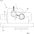
- the hook shape is best seen at the figure 4 .
- the weapon 100 is seen end by its front end.
- the stop 6 has a hook shape, the upper part of which acts as a lug 7 opposing the vertical withdrawal of the weapon 100.
- the hook stop 6 comprises an inclined plane 11 which is oriented so such that, when the weapon 100 is driven by the caliper 2, the barrel of the weapon 100 tends to climb the inclined plane 11 and rises in a direction D which moves it away from the surface 200 and pushes it at the bottom of hook 6. The weapon is thus securely held in position against accidental withdrawal. When the surface 200 is horizontal, this separation of the barrel is against the effect of the weight of the weapon.
- the device comprises means making it possible to prevent the movements of the weapon 100 in the direction of the pivot axis 4, then it can be installed on surfaces 200 having various orientations such as for example vertically or even at the level of a vehicle ceiling without fear of the weapon falling off.
Landscapes
- Engineering & Computer Science (AREA)
- General Engineering & Computer Science (AREA)
- Mechanical Engineering (AREA)
- Aiming, Guidance, Guns With A Light Source, Armor, Camouflage, And Targets (AREA)
- Toys (AREA)
- Fittings On The Vehicle Exterior For Carrying Loads, And Devices For Holding Or Mounting Articles (AREA)
- Braking Arrangements (AREA)
Abstract
Description
- Le domaine technique de l'invention est celui des supports pour les armes individuelles de type fusil qui sont embarquées à bord de véhicules militaires.
- Il est connu de longue date de fixer les armes des fantassins à bord des véhicules militaires pour assurer la protection et l'accès à ces armes tout en maintenant la sécurité des personnels et en rationalisant le rangement à bord des véhicules.
- Le brevet
US2018/0170268 décrit un support pour arme individuelle comportant un sabot pivotant autour d'un axe transversal. Le sabot est destiné à recevoir l'arrière de la crosse d'une arme. Lorsque le sabot est basculé vers l'avant autour de l'axe, l'utilisateur peut mettre en place l'arme dans le sabot. En faisant pivoter l'arme située dans le sabot jusqu'à la verticale, le canon de l'arme est amené dans un collier verrouillable électriquement qui maintient alors l'arme verticalement le long d'un mat. Pour retirer l'arme du support, l'utilisateur doit déverrouiller le collier et basculer l'arme vers l'avant. - Un tel dispositif est complexe du fait de l'équipement électrique nécessaire, qui est susceptible de pannes. En outre ce dispositif semble peu adapté à d'autres orientations de stockage de l'arme que la verticale.
- Le brevet
US3700147 divulgue un support pour arme individuelle comportant un sabot destiné à contenir la crosse de l'arme. Ce sabot est monté pivotant par rapport à un support vis-à-vis duquel il est rappelé en position par un moyen élastique. Une butée de forme indéfinie permet d'arrêter le mouvement de pivot de l'arme entrainée par le sabot. - La demande de brevet
US2003/042283 décrit un support pour un outil, un arc ou un fusil, support comportant une paire d'étriers qui sont destinés à recevoir chacun une branche de l'outil ou de l'arc. Les étriers sont montés pivotant par rapport à un support auquel ils sont chacun reliés par un moyen élastique exerçant un couple de pivotement autour d'un axe perpendiculaire au support. - Aucun de ces dispositifs n'assure un maintien simple et fiable d'une arme sur un support pouvant adopter plusieurs orientations.
- L'invention propose un support de conception simple et fiable, support pouvant par ailleurs être mis en œuvre d'une seule main et pouvant être positionné suivant différentes orientations, en particulier sur un plan proche de l'horizontale.
- Ainsi, l'invention a pour objet un support pour arme individuelle qui est destiné à être rendu solidaire d'une surface, support comportant, d'une part un étrier comportant au moins deux zones d'appui entre lesquelles l'arme est destinée à être placée, étrier qui est destiné à être rendu solidaire de la surface grâce à un axe de pivot, le support comportant un moyen de rappel élastique qui applique un couple faisant pivoter l'étrier par rapport à la surface et autour de l'axe de pivot, les zones d'appui pouvant alors transmettre le couple à l'arme, support comportant d'autre part une butée destinée à être rendue solidaire de la surface et disposée à distance de l'étrier, butée pouvant arrêter le pivotement de l'arme lorsqu'elle est soumise au couple transmis par les zones d'appui de l'étrier, support caractérisé en ce que la butée comporte un ergot positionné de manière à s'opposer au retrait de l'arme par translation selon une direction parallèle à l'axe de pivot, la butée et son ergot formant un crochet qui est orienté de manière telle que l'arme soit poussée par le couple communiqué par l'étrier vers le fond du crochet, le crochet comportant un plan incliné ayant pour effet d'écarter l'arme à distance de la surface sous l'effet du couple communiqué par l'étrier.
- Avantageusement, chaque zone d'appui de l'étrier pourra également comporter un ergot positionné de manière à s'opposer au retrait de l'arme par translation selon une direction parallèle à l'axe de pivot.
- Selon un mode de réalisation, le support pourra comporter une platine solidaire de l'étrier pivotant, platine comportant un arrêtoir destiné à interférer avec une crosse de l'arme pour en arrêter le glissement longitudinal en direction de l'arrêtoir.
- Avantageusement, la platine pourra comporter un sabot formant l'arrêtoir, sabot délimitant un logement qui sera destiné à recevoir la crosse de l'arme pour limiter les mouvements transversaux de celle-ci.
- Selon un mode de réalisation, le support pourra comporter une plaque fixe qui sera destinée à être rendue solidaire de la surface, plaque comportant une face d'appui qui sera destinée à interférer avec une crosse de l'arme pour en arrêter le glissement longitudinal en direction de la face d'appui.
- Avantageusement, la plaque fixe pourra comporter un rebord au niveau de sa face d'appui, rebord qui sera destiné à interférer avec la crosse de l'arme pour en bloquer les mouvements selon une direction parallèle à l'axe de pivot.
- L'invention sera mieux comprise à la lecture de la description suivante, description faite au regard des dessins annexés dans lesquels :
- [
Fig 1a ] représente une vue de dessus d'un dispositif selon un premier mode de réalisation de l'invention. - [
Fig 1b ] représente une vue de côté du dispositif selon ce premier mode de réalisation. - [
Fig 2a ] représente une vue de dessus d'un dispositif selon un deuxième mode de réalisation de l'invention. - [
Fig 2b ] représente une vue de côté du dispositif selon ce deuxième mode de réalisation. - [
Fig 3a ] représente une vue de dessus d'un dispositif selon un troisième mode de réalisation de l'invention. - [
Fig 3b ] représente une vue de côté du dispositif selon ce troisième mode de réalisation. - [
Fig 4 ] représente une vue de face d'un crochet pouvant être utilisé dans les différents modes de réalisation. - Selon les figures la et 1b, un support 1 pour une arme individuelle longue 100, de type fusil automatique, est fixé à une surface 200 qui est ici horizontale. La surface pourra être par exemple une surface externe d'un véhicule au voisinage d'un trou d'homme. Le support 1 permet alors de positionner l'arme à proximité d'un observateur sortant son torse par le trou d'homme.
- Le support 1 comporte un étrier 2 qui comporte deux montants 3a et 3b, qui sont ici des tiges orientées perpendiculairement à la surface 200, et qui forment des zones d'appui 3a et 3b, situées de part et d'autre de l'arme 100, préférentiellement au niveau de la crosse. A mi-distance de chaque zone d'appui 3a et 3b se trouve un axe de pivot 4 qui solidarise l'étrier 2 avec la surface 200, permettant ainsi à l'étrier 2 de pouvoir pivoter relativement à la surface 200. L'axe de pivot 4 est perpendiculaire à la surface 200.
- Le support 1 comporte aussi un moyen de rappel élastique 5 qui est fixé de façon à exercer un effort entre l'étrier 2 et la surface 200 de façon à produire un couple de pivotement C autour de l'axe de pivot 4. Ce couple C tend à faire pivoter l'arme 100 autour de l'axe de pivot 4 mais celle-ci est arrêtée en rotation dans le sens du couple C par une butée 6 du support 1 qui est située à distance de l'étrier 2 et qui interfère avec une partie avant de l'arme 100, préférentiellement le canon.
- L'arme est ainsi maintenue dans un plan P qui est parallèle à la surface 200.
- La saisie de l'arme 200 est aisée puisque rien ne gêne son retrait suivant une direction parallèle à l'axe de pivot 4 et ce retrait peut se faire avec une main seulement.
- On notera que si la surface 200 est présentée horizontale, elle pourrait également être inclinée de façon permanente ou ponctuelle dans le cas de sollicitations de transport de l'arme dans un véhicule par exemple.
- L'Homme du Métier prendra soin de dimensionner l'effort produit par le moyen élastique 5 en tenant compte des contraintes générées par l'inclinaison de la surface 200 sur laquelle est fixé le dispositif 1.
- Si l'on souhaite également sécuriser le retrait de l'arme 100 contre des mouvements indésirables parallèles à l'axe 4, les extrémités des zones d'appui 3a et 3b et de la butée 6 pourront comporter des ergots 7 qui viendront en partie au-dessus de l'arme 100. Dans ce cas, le retrait de l'arme 100 se fera toujours à une main mais en faisant au préalable pivoter l'arme contre le couple C, ce qui permettra d'éloigner l'avant de l'arme de la butée 6 et de le dégager de l'ergot 7.
- En levant l'extrémité avant de l'arme 100, celle-ci pourra échapper à l'ergot 7 de la butée 6. On accompagne ensuite l'arme dans un mouvement de pivotement selon la direction imprimée par l'étrier 2 jusqu'à ce que les butées 3a et 3b n'exercent plus d'effort sur la crosse, ce qui permet le retrait de la partie arrière de l'arme de l'étrier 2.
- Les
figures 2a et 2b montrent un deuxième mode de réalisation dans lequel le support 1 comporte une platine 8 solidaire de l'étrier pivotant 2. La platine 8 s'étend jusqu'à l'arrière de la crosse de l'arme 10 et comporte un arrêtoir 9 qui comporte ici un sabot 10 entourant l'arrière de la crosse. L'arrêtoir 9 a pour fonction de bloquer les mouvements longitudinaux de l'arme 100 en direction de l'arrière AR, vers l'arrêtoir 9. Le sabot 10 permet, lors de la mise en place de l'arme sur le support 1, d'aligner celle-ci entre les zones d'appui 3a et 3b de l'étrier. Le sabot 10 délimite un logement qui est destiné à recevoir la crosse de l'arme et qui permet de limiter les mouvements transversaux de celle-ci. On évite ainsi les mouvements transversaux parallèles à la surface 200 mais aussi les mouvements transversaux selon une direction parallèle à l'axe de pivot 4. - On note que, la platine 8 étant liée à l'étrier 2, celle-ci accompagne les mouvements de rotation de l'étrier 2, favorisant une mise en place aisée de l'arme 100 dans l'étrier 2.
- Le moyen élastique 5 comporte ici un ressort hélicoïdal 5 entourant l'axe 4.
- Le pivotement de l'arme 100 sous l'influence du couple C est, selon ce mode de réalisation, arrêté par une butée 6 qui comporte une forme en crochet qui sera détaillée plus loin en référence à la
figure 4 . - Les
figures 3a et 3b montrent un troisième mode de réalisation de l'invention dans lequel le support 1 comporte une plaque fixe 12 qui est rendue solidaire de la surface 200 selon des moyens classiquement connus de l'Homme du Métier, par exemple des vis. On assure ainsi une fixation robuste du support 1 avec la surface 200. - La plaque fixe 12 comporte aussi une face d'appui 13 destinée à arrêter le glissement longitudinal de l'arme 100 vers l'arrière AR, en direction de la face d'appui 13. La plaque fixe 12 comporte enfin un rebord 14 au niveau de sa face d'appui, rebord qui est destiné à retenir la crosse contre les mouvements parallèles à l'axe de pivot 4.
- La plaque fixe 12 ne tourne pas autour de l'axe 4 mais elle n'entrave pas la rotation de l'arme autour de l'axe de pivot 4 lorsqu'elle est libérée de l'emprise des zones d'appui 3a et 3b comme représenté sur la
figure 3b par la silhouette en position inclinée P2, ce qui permet une retrait extrêmement rapide de l'arme 100 depuis le support 1. - Là aussi, le pivotement de l'arme 100 sous l'influence du couple C communiqué par l'étrier 2 est arrêté par une butée 6 qui a une forme de crochet.
- Cette forme de crochet est mieux vue à la
figure 4 . L'arme 100 est vue en bout par son extrémité avant. La butée 6 comporte une forme en crochet dont la partie supérieure joue le rôle d'un ergot 7 s'opposant au retrait vertical de l'arme 100. On note que la butée en crochet 6 comporte un plan incliné 11 qui est orienté de manière telle que, lorsque l'arme 100 est entraînée par l'étrier 2, le canon de l'arme 100 tend à gravir le plan incliné 11 et s'élève dans une direction D qui l'écarte de la surface 200 et vient le pousser au fond du crochet 6. L'arme est ainsi maintenue en position de manière sûre contre un retrait accidentel. Lorsque la surface 200 est horizontale, cet écartement du canon se fait contre l'effet du poids de l'arme. - On note que, lorsque le dispositif comporte des moyens permettant d'empêcher les mouvements de l'arme 100 selon la direction de l'axe de pivot 4, alors il peut être installé sur des surfaces 200 présentant diverses orientations comme par exemple verticalement ou même au niveau d'un plafond du véhicule sans crainte de décrochement de l'arme.
Claims (6)
- Support (1) pour arme individuelle (100) destiné à être rendu solidaire d'une surface (200), support (1) comportant, d'une part un étrier (2) comportant au moins deux zones d'appui (3a,3b) entre lesquelles l'arme (100) est destinée à être placée, étrier (2) qui est destiné à être rendu solidaire de la surface (200) grâce à un axe de pivot (4), le support (1) comportant un moyen de rappel (5) élastique qui applique un couple faisant pivoter l'étrier (2) par rapport à la surface (200) et autour de l'axe de pivot (4), les zones d'appui (3a,3b) pouvant alors transmettre le couple à l'arme (100), support (1) comportant d'autre part une butée (6) destinée à être rendue solidaire de la surface (200) et disposée à distance de l'étrier (2), butée (6) pouvant arrêter le pivotement de l'arme (100) lorsqu'elle est soumise au couple transmis par les zones d'appui (3a,3b) de l'étrier (2), support caractérisé en ce que la butée (6) comporte un ergot (7) positionné de manière à s'opposer au retrait de l'arme (100) par translation selon une direction parallèle à l'axe de pivot (4), la butée (6) et son ergot (7) formant un crochet (6) qui est orienté de manière telle que l'arme (100) soit poussée par le couple communiqué par l'étrier (2) vers le fond du crochet (6), le crochet (6) comportant un plan incliné (11) ayant pour effet d'écarter l'arme (100) à distance de la surface (200) sous l'effet du couple communiqué par l'étrier (2).
- Support (1) pour arme individuelle (100) selon la revendication 1, caractérisé en ce que chaque zone d'appui (3a, 3b) de l'étrier (2) comporte un ergot (7) positionné de manière à s'opposer au retrait de l'arme (100) par translation selon une direction parallèle à l'axe de pivot (4) .
- Support (1) pour arme (100) selon la revendication 1, caractérisé en ce qu'il comporte une platine (8) solidaire de l'étrier (2) pivotant, platine (8) comportant un arrêtoir (9) destiné à interférer avec une crosse de l'arme (100) pour en arrêter le glissement longitudinal en direction de l'arrêtoir (9).
- Support (1) pour arme (100) selon la revendication 3, caractérisé en ce que la platine (8) comporte un sabot (10) formant l'arrêtoir (9), sabot (10) délimitant un logement qui est destiné à recevoir la crosse de l'arme (100) pour limiter les mouvements transversaux de celle-ci.
- Support (1) pour arme (100) selon la revendication 1, caractérisé en ce qu'il comporte une plaque fixe (12) qui est destinée à être rendue solidaire de la surface (200), plaque (12) comportant une face d'appui (13) qui est destinée à interférer avec une crosse de l'arme (100) pour en arrêter le glissement longitudinal en direction de la face (13) d'appui.
- Support (1) pour arme (100) selon la revendication 5, caractérisé en ce que la plaque fixe (13) comporte un rebord (14) au niveau de sa face d'appui (13), rebord (14) qui est destiné à interférer avec la crosse de l'arme (100) pour en bloquer les mouvements selon une direction parallèle à l'axe de pivot (4).
Applications Claiming Priority (1)
| Application Number | Priority Date | Filing Date | Title |
|---|---|---|---|
| FR1913995A FR3104694B1 (fr) | 2019-12-11 | 2019-12-11 | Support pour arme individuelle |
Publications (2)
| Publication Number | Publication Date |
|---|---|
| EP3835707A1 true EP3835707A1 (fr) | 2021-06-16 |
| EP3835707B1 EP3835707B1 (fr) | 2022-11-02 |
Family
ID=70613880
Family Applications (1)
| Application Number | Title | Priority Date | Filing Date |
|---|---|---|---|
| EP20209122.9A Active EP3835707B1 (fr) | 2019-12-11 | 2020-11-23 | Support pour arme individuelle |
Country Status (3)
| Country | Link |
|---|---|
| EP (1) | EP3835707B1 (fr) |
| ES (1) | ES2934611T3 (fr) |
| FR (1) | FR3104694B1 (fr) |
Citations (3)
| Publication number | Priority date | Publication date | Assignee | Title |
|---|---|---|---|---|
| US3700147A (en) | 1970-09-14 | 1972-10-24 | Damon A Vaughn | Weapon carrier |
| US20030042283A1 (en) | 2001-08-31 | 2003-03-06 | Carnevali Jeffrey D. | Quick release tool mounting bracket |
| US20180170268A1 (en) | 2016-09-30 | 2018-06-21 | Richard Alan Fisher | Vehicle gun rack |
-
2019
- 2019-12-11 FR FR1913995A patent/FR3104694B1/fr active Active
-
2020
- 2020-11-23 EP EP20209122.9A patent/EP3835707B1/fr active Active
- 2020-11-23 ES ES20209122T patent/ES2934611T3/es active Active
Patent Citations (3)
| Publication number | Priority date | Publication date | Assignee | Title |
|---|---|---|---|---|
| US3700147A (en) | 1970-09-14 | 1972-10-24 | Damon A Vaughn | Weapon carrier |
| US20030042283A1 (en) | 2001-08-31 | 2003-03-06 | Carnevali Jeffrey D. | Quick release tool mounting bracket |
| US20180170268A1 (en) | 2016-09-30 | 2018-06-21 | Richard Alan Fisher | Vehicle gun rack |
Also Published As
| Publication number | Publication date |
|---|---|
| FR3104694A1 (fr) | 2021-06-18 |
| FR3104694B1 (fr) | 2022-12-02 |
| ES2934611T3 (es) | 2023-02-23 |
| EP3835707B1 (fr) | 2022-11-02 |
Similar Documents
| Publication | Publication Date | Title |
|---|---|---|
| CH619370A5 (fr) | ||
| FR2564715A1 (fr) | Siege de securite pour enfant a bord d'une automobile | |
| FR3023593A1 (fr) | Systeme de fixation rapide d'un accessoire sur le corps d'un drone | |
| FR2644412A1 (fr) | Systeme de table escamotable | |
| EP3249343B1 (fr) | Module de maintien de canon d'arme a feu et dispositif de support modulaire pour arme a feu comprenant un tel module ainsi qu'un module de maintien de crosse | |
| EP2650583A1 (fr) | Bras porteur de charge réglable, dispositif de suspension d'une charge | |
| EP1652559B1 (fr) | Dispositif de réglage pour accessoire tel une talonnière de fixation de ski | |
| EP3835707B1 (fr) | Support pour arme individuelle | |
| CH676086A5 (fr) | ||
| EP0263727A1 (fr) | Dispositif pour creuser des tranchées | |
| EP1302607A1 (fr) | Appareil de levage pour la mise en place de plaques au plafond | |
| EP2330024B1 (fr) | Système de lestage et d'équilibrage pour tracteur | |
| FR2760375A1 (fr) | Raquette a neige | |
| EP0428480A2 (fr) | Fixation de sécurité à plaque | |
| WO1997017569A1 (fr) | Ensemble de support d'une perche de prise de son | |
| EP0020979A1 (fr) | Procédé et dispositif d'accouplement et de désaccouplement d'un moteur et d'un élément d'impression | |
| FR2791767A1 (fr) | Crosse de fusil a busc reglable et fusil equipe d'une telle crosse | |
| EP1589313B1 (fr) | Appareil d'équipement accessoire pour chasseur | |
| FR2763925A1 (fr) | Dispositif de deplacement de charge | |
| EP0447338B1 (fr) | Dispositif porte-charge adaptable sur l'attelage à rotule d'un véhicule | |
| FR3016959A1 (fr) | Systeme de fixation amovible d'une lunette sur une arme | |
| EP0282385B1 (fr) | Dispositif d'ancrage sur chevrons pour travaux de toiture | |
| WO2021111072A1 (fr) | Engin de loisirs à guidon escamotable | |
| EP0379415A1 (fr) | Dispositif d'ancrage avec pièce de stabilisation | |
| FR2552578A1 (fr) | Dispositif compensateur du moment de basculement d'un appareil optique pose sur une plate-forme de trepied |
Legal Events
| Date | Code | Title | Description |
|---|---|---|---|
| PUAI | Public reference made under article 153(3) epc to a published international application that has entered the european phase |
Free format text: ORIGINAL CODE: 0009012 |
|
| STAA | Information on the status of an ep patent application or granted ep patent |
Free format text: STATUS: THE APPLICATION HAS BEEN PUBLISHED |
|
| AK | Designated contracting states |
Kind code of ref document: A1 Designated state(s): AL AT BE BG CH CY CZ DE DK EE ES FI FR GB GR HR HU IE IS IT LI LT LU LV MC MK MT NL NO PL PT RO RS SE SI SK SM TR |
|
| STAA | Information on the status of an ep patent application or granted ep patent |
Free format text: STATUS: REQUEST FOR EXAMINATION WAS MADE |
|
| 17P | Request for examination filed |
Effective date: 20211216 |
|
| RBV | Designated contracting states (corrected) |
Designated state(s): AL AT BE BG CH CY CZ DE DK EE ES FI FR GB GR HR HU IE IS IT LI LT LU LV MC MK MT NL NO PL PT RO RS SE SI SK SM TR |
|
| GRAP | Despatch of communication of intention to grant a patent |
Free format text: ORIGINAL CODE: EPIDOSNIGR1 |
|
| STAA | Information on the status of an ep patent application or granted ep patent |
Free format text: STATUS: GRANT OF PATENT IS INTENDED |
|
| RIC1 | Information provided on ipc code assigned before grant |
Ipc: F41B 5/14 20060101ALI20220512BHEP Ipc: B60R 7/14 20060101ALI20220512BHEP Ipc: F41A 23/18 20060101AFI20220512BHEP |
|
| INTG | Intention to grant announced |
Effective date: 20220527 |
|
| GRAS | Grant fee paid |
Free format text: ORIGINAL CODE: EPIDOSNIGR3 |
|
| GRAA | (expected) grant |
Free format text: ORIGINAL CODE: 0009210 |
|
| STAA | Information on the status of an ep patent application or granted ep patent |
Free format text: STATUS: THE PATENT HAS BEEN GRANTED |
|
| AK | Designated contracting states |
Kind code of ref document: B1 Designated state(s): AL AT BE BG CH CY CZ DE DK EE ES FI FR GB GR HR HU IE IS IT LI LT LU LV MC MK MT NL NO PL PT RO RS SE SI SK SM TR |
|
| REG | Reference to a national code |
Ref country code: GB Ref legal event code: FG4D Free format text: NOT ENGLISH |
|
| REG | Reference to a national code |
Ref country code: CH Ref legal event code: EP Ref country code: AT Ref legal event code: REF Ref document number: 1529033 Country of ref document: AT Kind code of ref document: T Effective date: 20221115 |
|
| REG | Reference to a national code |
Ref country code: DE Ref legal event code: R096 Ref document number: 602020006034 Country of ref document: DE |
|
| REG | Reference to a national code |
Ref country code: IE Ref legal event code: FG4D Free format text: LANGUAGE OF EP DOCUMENT: FRENCH |
|
| REG | Reference to a national code |
Ref country code: NL Ref legal event code: FP |
|
| REG | Reference to a national code |
Ref country code: SE Ref legal event code: TRGR |
|
| REG | Reference to a national code |
Ref country code: ES Ref legal event code: FG2A Ref document number: 2934611 Country of ref document: ES Kind code of ref document: T3 Effective date: 20230223 |
|
| REG | Reference to a national code |
Ref country code: LT Ref legal event code: MG9D |
|
| REG | Reference to a national code |
Ref country code: AT Ref legal event code: MK05 Ref document number: 1529033 Country of ref document: AT Kind code of ref document: T Effective date: 20221102 |
|
| PG25 | Lapsed in a contracting state [announced via postgrant information from national office to epo] |
Ref country code: PT Free format text: LAPSE BECAUSE OF FAILURE TO SUBMIT A TRANSLATION OF THE DESCRIPTION OR TO PAY THE FEE WITHIN THE PRESCRIBED TIME-LIMIT Effective date: 20230302 Ref country code: NO Free format text: LAPSE BECAUSE OF FAILURE TO SUBMIT A TRANSLATION OF THE DESCRIPTION OR TO PAY THE FEE WITHIN THE PRESCRIBED TIME-LIMIT Effective date: 20230202 Ref country code: LT Free format text: LAPSE BECAUSE OF FAILURE TO SUBMIT A TRANSLATION OF THE DESCRIPTION OR TO PAY THE FEE WITHIN THE PRESCRIBED TIME-LIMIT Effective date: 20221102 Ref country code: FI Free format text: LAPSE BECAUSE OF FAILURE TO SUBMIT A TRANSLATION OF THE DESCRIPTION OR TO PAY THE FEE WITHIN THE PRESCRIBED TIME-LIMIT Effective date: 20221102 Ref country code: AT Free format text: LAPSE BECAUSE OF FAILURE TO SUBMIT A TRANSLATION OF THE DESCRIPTION OR TO PAY THE FEE WITHIN THE PRESCRIBED TIME-LIMIT Effective date: 20221102 |
|
| PG25 | Lapsed in a contracting state [announced via postgrant information from national office to epo] |
Ref country code: RS Free format text: LAPSE BECAUSE OF FAILURE TO SUBMIT A TRANSLATION OF THE DESCRIPTION OR TO PAY THE FEE WITHIN THE PRESCRIBED TIME-LIMIT Effective date: 20221102 Ref country code: PL Free format text: LAPSE BECAUSE OF FAILURE TO SUBMIT A TRANSLATION OF THE DESCRIPTION OR TO PAY THE FEE WITHIN THE PRESCRIBED TIME-LIMIT Effective date: 20221102 Ref country code: LV Free format text: LAPSE BECAUSE OF FAILURE TO SUBMIT A TRANSLATION OF THE DESCRIPTION OR TO PAY THE FEE WITHIN THE PRESCRIBED TIME-LIMIT Effective date: 20221102 Ref country code: IS Free format text: LAPSE BECAUSE OF FAILURE TO SUBMIT A TRANSLATION OF THE DESCRIPTION OR TO PAY THE FEE WITHIN THE PRESCRIBED TIME-LIMIT Effective date: 20230302 Ref country code: HR Free format text: LAPSE BECAUSE OF FAILURE TO SUBMIT A TRANSLATION OF THE DESCRIPTION OR TO PAY THE FEE WITHIN THE PRESCRIBED TIME-LIMIT Effective date: 20221102 Ref country code: GR Free format text: LAPSE BECAUSE OF FAILURE TO SUBMIT A TRANSLATION OF THE DESCRIPTION OR TO PAY THE FEE WITHIN THE PRESCRIBED TIME-LIMIT Effective date: 20230203 |
|
| PG25 | Lapsed in a contracting state [announced via postgrant information from national office to epo] |
Ref country code: SM Free format text: LAPSE BECAUSE OF FAILURE TO SUBMIT A TRANSLATION OF THE DESCRIPTION OR TO PAY THE FEE WITHIN THE PRESCRIBED TIME-LIMIT Effective date: 20221102 Ref country code: RO Free format text: LAPSE BECAUSE OF FAILURE TO SUBMIT A TRANSLATION OF THE DESCRIPTION OR TO PAY THE FEE WITHIN THE PRESCRIBED TIME-LIMIT Effective date: 20221102 Ref country code: IT Free format text: LAPSE BECAUSE OF NON-PAYMENT OF DUE FEES Effective date: 20221123 Ref country code: EE Free format text: LAPSE BECAUSE OF FAILURE TO SUBMIT A TRANSLATION OF THE DESCRIPTION OR TO PAY THE FEE WITHIN THE PRESCRIBED TIME-LIMIT Effective date: 20221102 Ref country code: DK Free format text: LAPSE BECAUSE OF FAILURE TO SUBMIT A TRANSLATION OF THE DESCRIPTION OR TO PAY THE FEE WITHIN THE PRESCRIBED TIME-LIMIT Effective date: 20221102 Ref country code: CZ Free format text: LAPSE BECAUSE OF FAILURE TO SUBMIT A TRANSLATION OF THE DESCRIPTION OR TO PAY THE FEE WITHIN THE PRESCRIBED TIME-LIMIT Effective date: 20221102 |
|
| REG | Reference to a national code |
Ref country code: DE Ref legal event code: R097 Ref document number: 602020006034 Country of ref document: DE |
|
| PG25 | Lapsed in a contracting state [announced via postgrant information from national office to epo] |
Ref country code: SK Free format text: LAPSE BECAUSE OF FAILURE TO SUBMIT A TRANSLATION OF THE DESCRIPTION OR TO PAY THE FEE WITHIN THE PRESCRIBED TIME-LIMIT Effective date: 20221102 Ref country code: LU Free format text: LAPSE BECAUSE OF NON-PAYMENT OF DUE FEES Effective date: 20221123 Ref country code: AL Free format text: LAPSE BECAUSE OF FAILURE TO SUBMIT A TRANSLATION OF THE DESCRIPTION OR TO PAY THE FEE WITHIN THE PRESCRIBED TIME-LIMIT Effective date: 20221102 |
|
| PLBE | No opposition filed within time limit |
Free format text: ORIGINAL CODE: 0009261 |
|
| STAA | Information on the status of an ep patent application or granted ep patent |
Free format text: STATUS: NO OPPOSITION FILED WITHIN TIME LIMIT |
|
| 26N | No opposition filed |
Effective date: 20230803 |
|
| PG25 | Lapsed in a contracting state [announced via postgrant information from national office to epo] |
Ref country code: IE Free format text: LAPSE BECAUSE OF NON-PAYMENT OF DUE FEES Effective date: 20221123 |
|
| PG25 | Lapsed in a contracting state [announced via postgrant information from national office to epo] |
Ref country code: SI Free format text: LAPSE BECAUSE OF FAILURE TO SUBMIT A TRANSLATION OF THE DESCRIPTION OR TO PAY THE FEE WITHIN THE PRESCRIBED TIME-LIMIT Effective date: 20221102 |
|
| PG25 | Lapsed in a contracting state [announced via postgrant information from national office to epo] |
Ref country code: IT Free format text: LAPSE BECAUSE OF NON-PAYMENT OF DUE FEES Effective date: 20221123 Ref country code: CY Free format text: LAPSE BECAUSE OF FAILURE TO SUBMIT A TRANSLATION OF THE DESCRIPTION OR TO PAY THE FEE WITHIN THE PRESCRIBED TIME-LIMIT Effective date: 20221102 |
|
| PGRI | Patent reinstated in contracting state [announced from national office to epo] |
Ref country code: IT Effective date: 20221130 |
|
| PG25 | Lapsed in a contracting state [announced via postgrant information from national office to epo] |
Ref country code: MK Free format text: LAPSE BECAUSE OF FAILURE TO SUBMIT A TRANSLATION OF THE DESCRIPTION OR TO PAY THE FEE WITHIN THE PRESCRIBED TIME-LIMIT Effective date: 20221102 |
|
| PG25 | Lapsed in a contracting state [announced via postgrant information from national office to epo] |
Ref country code: MC Free format text: LAPSE BECAUSE OF FAILURE TO SUBMIT A TRANSLATION OF THE DESCRIPTION OR TO PAY THE FEE WITHIN THE PRESCRIBED TIME-LIMIT Effective date: 20221102 |
|
| PG25 | Lapsed in a contracting state [announced via postgrant information from national office to epo] |
Ref country code: TR Free format text: LAPSE BECAUSE OF FAILURE TO SUBMIT A TRANSLATION OF THE DESCRIPTION OR TO PAY THE FEE WITHIN THE PRESCRIBED TIME-LIMIT Effective date: 20221102 Ref country code: MC Free format text: LAPSE BECAUSE OF FAILURE TO SUBMIT A TRANSLATION OF THE DESCRIPTION OR TO PAY THE FEE WITHIN THE PRESCRIBED TIME-LIMIT Effective date: 20221102 |
|
| REG | Reference to a national code |
Ref country code: CH Ref legal event code: PL |
|
| PG25 | Lapsed in a contracting state [announced via postgrant information from national office to epo] |
Ref country code: CH Free format text: LAPSE BECAUSE OF NON-PAYMENT OF DUE FEES Effective date: 20231130 |
|
| PG25 | Lapsed in a contracting state [announced via postgrant information from national office to epo] |
Ref country code: CH Free format text: LAPSE BECAUSE OF NON-PAYMENT OF DUE FEES Effective date: 20231130 Ref country code: BG Free format text: LAPSE BECAUSE OF FAILURE TO SUBMIT A TRANSLATION OF THE DESCRIPTION OR TO PAY THE FEE WITHIN THE PRESCRIBED TIME-LIMIT Effective date: 20221102 |
|
| PG25 | Lapsed in a contracting state [announced via postgrant information from national office to epo] |
Ref country code: MT Free format text: LAPSE BECAUSE OF FAILURE TO SUBMIT A TRANSLATION OF THE DESCRIPTION OR TO PAY THE FEE WITHIN THE PRESCRIBED TIME-LIMIT Effective date: 20221102 |
|
| GBPC | Gb: european patent ceased through non-payment of renewal fee |
Effective date: 20241123 |
|
| PG25 | Lapsed in a contracting state [announced via postgrant information from national office to epo] |
Ref country code: HU Free format text: LAPSE BECAUSE OF FAILURE TO SUBMIT A TRANSLATION OF THE DESCRIPTION OR TO PAY THE FEE WITHIN THE PRESCRIBED TIME-LIMIT; INVALID AB INITIO Effective date: 20201123 |
|
| PG25 | Lapsed in a contracting state [announced via postgrant information from national office to epo] |
Ref country code: GB Free format text: LAPSE BECAUSE OF NON-PAYMENT OF DUE FEES Effective date: 20241123 |
|
| PGFP | Annual fee paid to national office [announced via postgrant information from national office to epo] |
Ref country code: NL Payment date: 20251022 Year of fee payment: 6 |
|
| PGFP | Annual fee paid to national office [announced via postgrant information from national office to epo] |
Ref country code: DE Payment date: 20251022 Year of fee payment: 6 |
|
| PGFP | Annual fee paid to national office [announced via postgrant information from national office to epo] |
Ref country code: IT Payment date: 20251022 Year of fee payment: 6 |
|
| PGFP | Annual fee paid to national office [announced via postgrant information from national office to epo] |
Ref country code: FR Payment date: 20251023 Year of fee payment: 6 |
|
| PGFP | Annual fee paid to national office [announced via postgrant information from national office to epo] |
Ref country code: BE Payment date: 20251022 Year of fee payment: 6 |
|
| PGFP | Annual fee paid to national office [announced via postgrant information from national office to epo] |
Ref country code: SE Payment date: 20251022 Year of fee payment: 6 |
|
| PGFP | Annual fee paid to national office [announced via postgrant information from national office to epo] |
Ref country code: ES Payment date: 20251201 Year of fee payment: 6 |