EP3835701A1 - Double heat exchanger with orthogonal gas flow - Google Patents
Double heat exchanger with orthogonal gas flow Download PDFInfo
- Publication number
- EP3835701A1 EP3835701A1 EP20212535.7A EP20212535A EP3835701A1 EP 3835701 A1 EP3835701 A1 EP 3835701A1 EP 20212535 A EP20212535 A EP 20212535A EP 3835701 A1 EP3835701 A1 EP 3835701A1
- Authority
- EP
- European Patent Office
- Prior art keywords
- cooling
- exchanger
- cooling system
- axis
- compressed air
- Prior art date
- Legal status (The legal status is an assumption and is not a legal conclusion. Google has not performed a legal analysis and makes no representation as to the accuracy of the status listed.)
- Pending
Links
- 239000007789 gas Substances 0.000 claims abstract description 90
- 238000001816 cooling Methods 0.000 claims abstract description 66
- 239000002826 coolant Substances 0.000 claims description 23
- 239000000110 cooling liquid Substances 0.000 claims description 21
- 239000007788 liquid Substances 0.000 claims description 16
- 238000005192 partition Methods 0.000 claims description 7
- 239000012530 fluid Substances 0.000 claims description 4
- XLYOFNOQVPJJNP-UHFFFAOYSA-N water Substances O XLYOFNOQVPJJNP-UHFFFAOYSA-N 0.000 description 19
- 238000002485 combustion reaction Methods 0.000 description 10
- 230000006835 compression Effects 0.000 description 8
- 238000007906 compression Methods 0.000 description 8
- 238000011144 upstream manufacturing Methods 0.000 description 7
- 238000000926 separation method Methods 0.000 description 4
- MWUXSHHQAYIFBG-UHFFFAOYSA-N Nitric oxide Chemical compound O=[N] MWUXSHHQAYIFBG-UHFFFAOYSA-N 0.000 description 3
- 239000000498 cooling water Substances 0.000 description 3
- 235000021183 entrée Nutrition 0.000 description 3
- 239000013529 heat transfer fluid Substances 0.000 description 3
- 238000009835 boiling Methods 0.000 description 2
- 239000012809 cooling fluid Substances 0.000 description 2
- 230000000694 effects Effects 0.000 description 2
- 239000003344 environmental pollutant Substances 0.000 description 2
- 230000004907 flux Effects 0.000 description 2
- 231100000719 pollutant Toxicity 0.000 description 2
- 230000000930 thermomechanical effect Effects 0.000 description 2
- IJGRMHOSHXDMSA-UHFFFAOYSA-N Atomic nitrogen Chemical compound N#N IJGRMHOSHXDMSA-UHFFFAOYSA-N 0.000 description 1
- 208000031968 Cadaver Diseases 0.000 description 1
- 230000015572 biosynthetic process Effects 0.000 description 1
- 239000003054 catalyst Substances 0.000 description 1
- 239000000112 cooling gas Substances 0.000 description 1
- 230000001747 exhibiting effect Effects 0.000 description 1
- 239000003546 flue gas Substances 0.000 description 1
- 239000000446 fuel Substances 0.000 description 1
- 238000010438 heat treatment Methods 0.000 description 1
Images


Classifications
-
- F—MECHANICAL ENGINEERING; LIGHTING; HEATING; WEAPONS; BLASTING
- F28—HEAT EXCHANGE IN GENERAL
- F28D—HEAT-EXCHANGE APPARATUS, NOT PROVIDED FOR IN ANOTHER SUBCLASS, IN WHICH THE HEAT-EXCHANGE MEDIA DO NOT COME INTO DIRECT CONTACT
- F28D7/00—Heat-exchange apparatus having stationary tubular conduit assemblies for both heat-exchange media, the media being in contact with different sides of a conduit wall
- F28D7/16—Heat-exchange apparatus having stationary tubular conduit assemblies for both heat-exchange media, the media being in contact with different sides of a conduit wall the conduits being arranged in parallel spaced relation
- F28D7/1684—Heat-exchange apparatus having stationary tubular conduit assemblies for both heat-exchange media, the media being in contact with different sides of a conduit wall the conduits being arranged in parallel spaced relation the conduits having a non-circular cross-section
-
- F—MECHANICAL ENGINEERING; LIGHTING; HEATING; WEAPONS; BLASTING
- F02—COMBUSTION ENGINES; HOT-GAS OR COMBUSTION-PRODUCT ENGINE PLANTS
- F02B—INTERNAL-COMBUSTION PISTON ENGINES; COMBUSTION ENGINES IN GENERAL
- F02B29/00—Engines characterised by provision for charging or scavenging not provided for in groups F02B25/00, F02B27/00 or F02B33/00 - F02B39/00; Details thereof
- F02B29/04—Cooling of air intake supply
- F02B29/045—Constructional details of the heat exchangers, e.g. pipes, plates, ribs, insulation, materials, or manufacturing and assembly
- F02B29/0456—Air cooled heat exchangers
-
- F—MECHANICAL ENGINEERING; LIGHTING; HEATING; WEAPONS; BLASTING
- F02—COMBUSTION ENGINES; HOT-GAS OR COMBUSTION-PRODUCT ENGINE PLANTS
- F02B—INTERNAL-COMBUSTION PISTON ENGINES; COMBUSTION ENGINES IN GENERAL
- F02B29/00—Engines characterised by provision for charging or scavenging not provided for in groups F02B25/00, F02B27/00 or F02B33/00 - F02B39/00; Details thereof
- F02B29/04—Cooling of air intake supply
- F02B29/045—Constructional details of the heat exchangers, e.g. pipes, plates, ribs, insulation, materials, or manufacturing and assembly
- F02B29/0462—Liquid cooled heat exchangers
-
- F—MECHANICAL ENGINEERING; LIGHTING; HEATING; WEAPONS; BLASTING
- F02—COMBUSTION ENGINES; HOT-GAS OR COMBUSTION-PRODUCT ENGINE PLANTS
- F02B—INTERNAL-COMBUSTION PISTON ENGINES; COMBUSTION ENGINES IN GENERAL
- F02B29/00—Engines characterised by provision for charging or scavenging not provided for in groups F02B25/00, F02B27/00 or F02B33/00 - F02B39/00; Details thereof
- F02B29/04—Cooling of air intake supply
- F02B29/045—Constructional details of the heat exchangers, e.g. pipes, plates, ribs, insulation, materials, or manufacturing and assembly
- F02B29/0475—Constructional details of the heat exchangers, e.g. pipes, plates, ribs, insulation, materials, or manufacturing and assembly the intake air cooler being combined with another device, e.g. heater, valve, compressor, filter or EGR cooler, or being assembled on a special engine location
-
- F—MECHANICAL ENGINEERING; LIGHTING; HEATING; WEAPONS; BLASTING
- F02—COMBUSTION ENGINES; HOT-GAS OR COMBUSTION-PRODUCT ENGINE PLANTS
- F02M—SUPPLYING COMBUSTION ENGINES IN GENERAL WITH COMBUSTIBLE MIXTURES OR CONSTITUENTS THEREOF
- F02M26/00—Engine-pertinent apparatus for adding exhaust gases to combustion-air, main fuel or fuel-air mixture, e.g. by exhaust gas recirculation [EGR] systems
- F02M26/13—Arrangement or layout of EGR passages, e.g. in relation to specific engine parts or for incorporation of accessories
- F02M26/22—Arrangement or layout of EGR passages, e.g. in relation to specific engine parts or for incorporation of accessories with coolers in the recirculation passage
- F02M26/29—Constructional details of the coolers, e.g. pipes, plates, ribs, insulation or materials
- F02M26/30—Connections of coolers to other devices, e.g. to valves, heaters, compressors or filters; Coolers characterised by their location on the engine
-
- F—MECHANICAL ENGINEERING; LIGHTING; HEATING; WEAPONS; BLASTING
- F02—COMBUSTION ENGINES; HOT-GAS OR COMBUSTION-PRODUCT ENGINE PLANTS
- F02M—SUPPLYING COMBUSTION ENGINES IN GENERAL WITH COMBUSTIBLE MIXTURES OR CONSTITUENTS THEREOF
- F02M26/00—Engine-pertinent apparatus for adding exhaust gases to combustion-air, main fuel or fuel-air mixture, e.g. by exhaust gas recirculation [EGR] systems
- F02M26/13—Arrangement or layout of EGR passages, e.g. in relation to specific engine parts or for incorporation of accessories
- F02M26/22—Arrangement or layout of EGR passages, e.g. in relation to specific engine parts or for incorporation of accessories with coolers in the recirculation passage
- F02M26/29—Constructional details of the coolers, e.g. pipes, plates, ribs, insulation or materials
- F02M26/32—Liquid-cooled heat exchangers
-
- F—MECHANICAL ENGINEERING; LIGHTING; HEATING; WEAPONS; BLASTING
- F28—HEAT EXCHANGE IN GENERAL
- F28D—HEAT-EXCHANGE APPARATUS, NOT PROVIDED FOR IN ANOTHER SUBCLASS, IN WHICH THE HEAT-EXCHANGE MEDIA DO NOT COME INTO DIRECT CONTACT
- F28D21/00—Heat-exchange apparatus not covered by any of the groups F28D1/00 - F28D20/00
- F28D21/0001—Recuperative heat exchangers
- F28D21/0003—Recuperative heat exchangers the heat being recuperated from exhaust gases
-
- F—MECHANICAL ENGINEERING; LIGHTING; HEATING; WEAPONS; BLASTING
- F28—HEAT EXCHANGE IN GENERAL
- F28D—HEAT-EXCHANGE APPARATUS, NOT PROVIDED FOR IN ANOTHER SUBCLASS, IN WHICH THE HEAT-EXCHANGE MEDIA DO NOT COME INTO DIRECT CONTACT
- F28D7/00—Heat-exchange apparatus having stationary tubular conduit assemblies for both heat-exchange media, the media being in contact with different sides of a conduit wall
- F28D7/0066—Multi-circuit heat-exchangers, e.g. integrating different heat exchange sections in the same unit or heat-exchangers for more than two fluids
-
- F—MECHANICAL ENGINEERING; LIGHTING; HEATING; WEAPONS; BLASTING
- F28—HEAT EXCHANGE IN GENERAL
- F28D—HEAT-EXCHANGE APPARATUS, NOT PROVIDED FOR IN ANOTHER SUBCLASS, IN WHICH THE HEAT-EXCHANGE MEDIA DO NOT COME INTO DIRECT CONTACT
- F28D21/00—Heat-exchange apparatus not covered by any of the groups F28D1/00 - F28D20/00
- F28D2021/0019—Other heat exchangers for particular applications; Heat exchange systems not otherwise provided for
- F28D2021/008—Other heat exchangers for particular applications; Heat exchange systems not otherwise provided for for vehicles
- F28D2021/0082—Charged air coolers
-
- Y—GENERAL TAGGING OF NEW TECHNOLOGICAL DEVELOPMENTS; GENERAL TAGGING OF CROSS-SECTIONAL TECHNOLOGIES SPANNING OVER SEVERAL SECTIONS OF THE IPC; TECHNICAL SUBJECTS COVERED BY FORMER USPC CROSS-REFERENCE ART COLLECTIONS [XRACs] AND DIGESTS
- Y02—TECHNOLOGIES OR APPLICATIONS FOR MITIGATION OR ADAPTATION AGAINST CLIMATE CHANGE
- Y02T—CLIMATE CHANGE MITIGATION TECHNOLOGIES RELATED TO TRANSPORTATION
- Y02T10/00—Road transport of goods or passengers
- Y02T10/10—Internal combustion engine [ICE] based vehicles
- Y02T10/12—Improving ICE efficiencies
Definitions
- the present invention relates to a high temperature gas cooling system.
- the present invention relates more particularly to the field of cooling systems for internal combustion engines, in particular the cooling of the intake gases of a heat engine of a motor vehicle.
- cooling system for an internal combustion engine, said cooling system comprising a heat exchanger connected to two circuits for circulating high temperature gas, in particular compressed air and burnt gas, and in which a fluid circulates. coolant.
- a motor vehicle equipped with a heat engine comprises an air intake circuit for supplying fresh air generally captured at the front of the vehicle and then filtered by means of an air filter, towards the thermal motor.
- a heat engine can include a supercharging system in order to increase the performance of said engine.
- the supercharging system comprises an air compression stage before it is admitted into the engine to be mixed with fuel.
- This compression stage can be associated with a turbine stage to together form a turbocharger or be an electrical compression module.
- the fresh air is compressed as it passes through the compression stage, which leads to an increase in its temperature, which is liable to reduce the efficiency of the engine.
- a precooler which is formed by an air-water exchanger.
- the air circulates in contact, for example in tubes housed in a chamber in which circulates cooling water coming from an engine cooling circuit.
- the cooling circuit can pass for example through the engine to also cool parts brought to high temperature of the engine such as the cylinder block and the cylinder head, the cooling water then taking care of calories, and then through a radiator to allow a deposit of said calories and their evacuation.
- the cooling water is circulated by a water pump driven by the heat engine or by an electric water pump.
- the recirculated gases are cooled before being mixed with the fresh or compressed air.
- the invention relates to the cooling of the compressed air and the cooling of the recirculated gases to the thermal inlet.
- the cooling system comprises a heat exchanger which circulates a heat transfer fluid around the recirculated gas circuit, which allows the heat transfer fluid to recover part of the heat from the burnt gases.
- the heat transfer fluid then circulates around the cylinders and transfers part of the recovered heat to them.
- the document FR3079880-A1 proposes a housing suitable for housing a heat exchanger for cooling the high pressure recirculated gases and a heat exchanger for cooling the compressed air upstream of the combustion engine intake ducts.
- the document proposes that the recirculated gas and mixed air inlets are both turned towards the exhaust face of the engine, resulting in a compact but less efficient cooling device.
- the temperatures of the gases are very high, the temperature of the casing can be significantly increased in certain places, in particular near the gas inlets, which can generate significant expansions.
- the object of the invention is a device for cooling gas and compressed air circuits exhibiting high temperatures upstream of the engine intake which overcomes the aforementioned problems.
- the present invention provides a cooling system for gas and compressed air, the temperatures of which are different, comprising a double-flow heat exchanger through which the gases pass along a first axis and the compressed air along a second axis,
- the axes of the gas and compressed air in the exchanger of the cooling system are substantially orthogonal, which makes it possible, on the one hand, not to accumulate in the same places of the exchanger casing, in particular near gas and compressed air inlets, large quantities of heat and on the other hand to allow expansion of the exchanger, in particular of the exchanger casing, in different directions.
- the recirculated gases and the compressed air pass through the crankcase and in particular the exchanger via cooling ducts which extend from an inlet wall to an outlet wall of the crankcase, the cross section of each cooling duct. cooling is oblong to present a large exchange surface.
- the following description relates to the cooling of recirculated burnt gases and compressed air upstream of the intake ducts of a heat engine, here of a motor vehicle.
- a thermal or internal combustion engine (not shown) of a motor vehicle comprises a so-called fresh air intake circuit generally captured from the front face of the vehicle capable of conveying this fresh air to the engine, in particular to an intake distributor. capable of distributing the intake air to intake ducts hollowed out in a cylinder head and connected to combustion chambers.
- the fresh air passes through a compression stage which may be the compressor stage of an engine turbocharger. It is also known to have an electric compressor.
- the air temperature has also increased, of the order of 200 ° C, which reduces the efficiency of the engine.
- the air downstream of the compression step in the direction of air flow must be cooled before it is admitted into the engine.
- the air must then pass through a cooling step which is generally formed by a heat exchanger of the gas-cooling liquid type.
- Said exchanger is known under the English name of “Precooler” for an upstream cooler.
- the coolant is water-based which circulates in an engine cooling circuit by means of a coolant pump.
- burnt gases result from the combustion in the combustion chamber of the engine. They are captured in an exhaust circuit and routed to the intake of the engine, in particular to the intake ducts of the engine, via a burnt gas recirculation circuit.
- the gases here are high pressure recirculated gases captured at an exhaust gas collection device. Said gases are known under the name of “EGR” gas in English. Said EGR gases will be referred to below as recirculated gases.
- the recirculated gases are at high temperature, of the order of 700 ° C. They need to be cooled before admission to the engine.
- the recirculated gas circuit also passes through a heat exchanger of the gas / coolant type.
- the heat exchanger for the fresh compressed air can be assembled with the heat exchanger for the recirculated gases.
- a gas cooling system 100 is obtained at the intake of the engine comprising a dual-flow exchanger 10.
- the compressed air and recirculated gas inlets are for example arranged on a wall of the casing of the dual-flow exchanger facing towards the air. exhaust face of the engine while the outlets face the intake face of the engine.
- the respective temperatures of the compressed air and of the recirculated gases are very different, which causes differential expansion problems between the two assembled exchangers and more clearly the walls of the casing of the double-flow exchanger.
- the significant difference in temperature between the recirculated gases and the intake air can lead to strong thermomechanical stresses which endanger the behavior of the exchanger and in particular of the exchanger casing.
- the walls of the exchanger are the walls of the casing of the exchanger.
- the bypass exchanger 10 comprises an inlet for the compressed air 11 arranged on a first gas inlet wall 12 and an inlet for the recirculated gases 21 arranged on a second inlet wall 22 for the gas inlet recirculated.
- the first inlet wall 12 is distinct from the second inlet wall 22 and more precisely the first inlet wall is adjacent and orthogonal to the second inlet wall 22.
- the compressed air flow passes through the exchanger along a rectilinear axis Xa between the first inlet wall 12 and the first air outlet wall 14 of the air-cooling liquid exchanger.
- the first air inlet 12 and outlet 14 walls are symmetrical with respect to a median plane orthogonal to the axis Xa.
- the flow of recirculated gas passes through the exchanger along a rectilinear axis Xg between the second inlet wall 22 and the second outlet wall 24 of the recirculated gas-cooling liquid exchanger.
- the second inlet 22 and outlet 24 walls are symmetrical with respect to a median plane orthogonal to the axis Xg.
- the axes of compressed air flow Xa and recirculated gas Xg are substantially orthogonal in order to present a smaller bulk with ease of assembly with other components of the engine.
- the axis compressed air flow can be angled with respect to the flow axis of the recirculated to facilitate the attachment of the exchanger with the engine and reduce the size of the assembly.
- the air intake circuit is connected by an inlet horn 13 fixed to the first inlet wall 12 of the casing and by an outlet horn 15 to the first outlet wall 14.
- the first outlet wall 14 is parallel and vis-à-vis with the first inlet wall 12.
- the downstream passage section in the direction of air flow of the fixed horn 13 is substantially equal to the passage section of the air-water heat exchanger. Indeed, the downstream passage section of the inlet horn 13 is as large as possible. It is substantially equal or even slightly greater than the passage section of the compressed air-coolant exchanger.
- heat exchanger passage section is understood to mean the cross section of the exchanger chamber, orthogonal to the axis of the direction of the flow Xa of compressed air.
- the exit horn 15 is substantially identical to the entrance horn.
- the upstream passage section of the outlet horn 15 is therefore equal to the passage section of the compressed air-coolant heat exchanger.
- the burnt gas recirculation circuit is also connected by a second inlet horn 23 fixed to the second inlet wall 22 of the exchanger and by an outlet horn 25 to a second outlet wall 24 in vis-à-vis the second inlet wall 22.
- the second inlet wall 22 is parallel to the second outlet wall 24.
- the second inlet 22 and outlet 24 walls are therefore orthogonal to the first walls of inlet 12 and outlet 14.
- the downstream passage section of the second inlet horn 23 fixed to the exchanger is substantially equal to the passage section of the recirculated gas-cooling liquid heat exchanger.
- the downstream passage section of the second inlet horn 23 is as large as possible. It is substantially equal to the passage section of the recirculated gas-cooling liquid exchanger, or even slightly greater.
- the heat exchanger passage section is understood to mean the cross section with respect to the direction of flow of the gases or of the air, of the heat exchanger chamber here the heat exchange chamber between the recirculated gases and the heat exchanger chamber. coolant, orthogonal to the Xg axis of the direction of the recirculated gas flow.
- the cooling liquid circuit is connected to the exchanger by cooling liquid inlet 32 and outlet 33 end fittings which extend respectively from a water inlet wall 31 and a water outlet wall. 34 of the exchanger.
- the liquid inlet 30 and the liquid outlet 35 defined by said end pieces are arranged at one end of the inlet 31 and outlet 34 walls in order to obtain the greatest possible length of the coolant path.
- the water inlet wall 31 is separate from the water outlet wall 34.
- the path of the water in the exchanger does not go back at the risk of altering the water. 'efficiency of the exchanger, as represented by the figure 3 .
- the cooling liquid circuit follows a path in the exchanger 10 along two parallel cooling branches 38, 39 and substantially symmetrical with respect to a planar median separation wall 36 parallel to the water inlet 31 and outlet 34 walls. .
- the exchanger 10 thus comprises two water chambers 41 and 42 for individually cooling the compressed air and the recirculated gases.
- tubular conduits 43,44 of oblong cross section for conducting respectively the compressed air and the recirculated gases between the inlet 12,22 and outlet 14,24 walls.
- the tubes guiding the air and the recirculated gases are placed perpendicularly. Thus, their respective expansions under the effect of heat do not take place in the same direction.
- the casing can therefore be deformed independently to adapt to the variation in length of the tubes in each direction.
- the volumes of the two chambers 41, 42 of the exchanger are substantially equal.
- the two branches 38, 39 for cooling and for circulating the cooling liquid inside the exchanger are separated by the central separation wall 36.
- the partition wall 36 comprises an opening 37 allowing communication between the two chambers 41, 42.
- Said opening 37 is drilled in the partition wall diametrically opposed to the liquid inlet 30 to allow an optimum exchange length, as long as possible.
- Said opening 37 is also arranged substantially diametrically opposite to the fluid outlet 35.
- the cooling liquid inlet 30 opens into the first cooling chamber 41 dedicated to heat exchanges with the compressed air.
- the axis of the tubular air ducts 43 is orthogonal to the direction of circulation of the water in the first chamber 41.
- the axes of circulation of the compressed air and of the cooling liquid are orthogonal or "cross-flow in English ”to improve the efficiency of heat exchange.
- the cooling liquid first passes into the cooling chamber 41 of the compressed air, becomes charged with heat and its temperature increases before joining the second cooling chamber 42 to cool the recirculated gases.
- the heat exchanges of the liquid with the compressed air and the recirculated gases take place in series to promote the cooling of the compressed air at the intake.
- the temperature difference between the coolant and the recirculated gases is less and can prevent the formation of condensate in the tubes.
- the path of the cooling liquid in the chambers 41,42 is directed along an axis substantially parallel to the central separation wall 36 in a first direction from the water inlet 30 to the opening 37, then in a second opposite direction. from the opening 37 towards the water outlet 35 forming a path with a U profile inside the exchanger 10 as shown in figure 3 .
- the axis of the tubular conduits of recirculated gas is parallel to the median separation wall and to the axis of water circulation in the second chamber 42.
- the axis of circulation of the cooling liquid substantially parallel to the axis Xg of the Tubular conduits for the circulation of recirculated gases make it possible to avoid water boiling phenomena.
- the double-flow exchanger 10 for cooling the compressed air and the recirculated gases is compact due to the assembly of the two exchangers, ensuring the thermomechanical constraints linked to the temperature differences between the two flows of air and gas, by a clever assembly presenting axes of circulation of orthogonal flows.
- the exchanger casing can therefore be deformed independently to adapt to the variation in length of the tubular conduits of compressed air 43 and of recirculated gas 44 in each of the two directions.
- the circulation flow of the recirculated gases can be in the same direction as that of the coolant or in the opposite direction.
- the heat exchanger according to the invention can relate to a field other than the automobile, to cool two gas streams at different temperatures.
Abstract
Système de refroidissement (100) de gaz et d'air compressé, comportant un échangeur de chaleur double-flux (10) traversé par les gaz selon un premier axe et l'air compressé selon un second axe,Caractérisé en ce que l'échangeur (10) comprend une chambre de refroidissement pour les gaz (42) accolée et communiquant avec une chambre de refroidissement pour l'air compressé (41) dans lesquelles l'axe du flux de gaz (Xg) est sensiblement orthogonal à l'axe du flux d'air compressé (Xa).Gas and compressed air cooling system (100), comprising a double-flow heat exchanger (10) traversed by the gases along a first axis and the compressed air along a second axis, characterized in that the exchanger (10) comprises a cooling chamber for the gases (42) contiguous and communicating with a cooling chamber for the compressed air (41) in which the axis of the gas flow (Xg) is substantially orthogonal to the axis of the compressed air flow (Xa).
Description
La présente invention concerne un système de refroidissement de gaz à hautes température.The present invention relates to a high temperature gas cooling system.
La présente invention concerne plus particulièrement le domaine des systèmes de refroidissement pour moteurs à combustion interne, notamment le refroidissement des gaz d'admission de moteur thermique de véhicule automobile.The present invention relates more particularly to the field of cooling systems for internal combustion engines, in particular the cooling of the intake gases of a heat engine of a motor vehicle.
Elle concerne plus particulièrement un système de refroidissement pour moteur à combustion interne, ledit système de refroidissement comprenant un échangeur thermique connecté à deux circuits de circulation de gaz à haute température, notamment d'air compressé et de gaz brulés, et dans lequel circule un fluide caloporteur.It relates more particularly to a cooling system for an internal combustion engine, said cooling system comprising a heat exchanger connected to two circuits for circulating high temperature gas, in particular compressed air and burnt gas, and in which a fluid circulates. coolant.
De manière connue, un véhicule automobile équipé d'un moteur thermique comprend un circuit d'admission d'air pour amener de l'air frais capté généralement au niveau de la face avant du véhicule puis filtré grâce à un filtre à air, vers le moteur thermique.In a known manner, a motor vehicle equipped with a heat engine comprises an air intake circuit for supplying fresh air generally captured at the front of the vehicle and then filtered by means of an air filter, towards the thermal motor.
De manière connue, un moteur thermique peut comprendre un système de suralimentation afin d'accroitre les performances dudit moteur. Le système de suralimentation comprend un étage de compression d'air avant son admission dans le moteur pour être mélangé avec du carburant. Cet étage de compression peut être associé avec un étage de turbine pour former ensemble un turbocompresseur ou être un module de compression électrique.In known manner, a heat engine can include a supercharging system in order to increase the performance of said engine. The supercharging system comprises an air compression stage before it is admitted into the engine to be mixed with fuel. This compression stage can be associated with a turbine stage to together form a turbocharger or be an electrical compression module.
Pour améliorer le rendement dudit moteur thermique, l'air frais est compressé au passage de l'étage de compression, ce qui entraine une augmentation de sa température, ce qui est susceptible de réduire l'efficacité du moteur.To improve the efficiency of said heat engine, the fresh air is compressed as it passes through the compression stage, which leads to an increase in its temperature, which is liable to reduce the efficiency of the engine.
Il est donc connu de faire passer l'air compressé après l'étage de compression et en amont du moteur dans un étage de refroidissement appelé couramment « precooler » qui est formé par un échangeur air-eau. Dans ledit échangeur, l'air circule en contact par exemple dans des tubes logés dans une chambre dans laquelle circule de l'eau de refroidissement provenant d'un circuit de refroidissement du moteur. Le circuit de refroidissement peut passer par exemple au travers du moteur pour refroidir également des parties portées à haute température du moteur comme le carter-cylindres et la culasse, l'eau de refroidissement se chargeant alors de calories, et puis par un radiateur pour permettre une dépose desdites calories et leur évacuation. La circulation de l'eau de refroidissement est effectuée grâce à une pompe à eau entrainée par le moteur thermique ou par une pompe à eau électrique.It is therefore known practice to pass the compressed air after the compression stage and upstream of the engine in a cooling stage commonly called a “precooler” which is formed by an air-water exchanger. In said exchanger, the air circulates in contact, for example in tubes housed in a chamber in which circulates cooling water coming from an engine cooling circuit. The cooling circuit can pass for example through the engine to also cool parts brought to high temperature of the engine such as the cylinder block and the cylinder head, the cooling water then taking care of calories, and then through a radiator to allow a deposit of said calories and their evacuation. The cooling water is circulated by a water pump driven by the heat engine or by an electric water pump.
Pour réduire des rejets de polluants générés par la combustion, des gaz brulés peuvent être ramenés depuis l'échappement c'est-à-dire en aval de la combustion dans les cylindres, vers les conduits d'admission du moteur. Les gaz sont nommés gaz recirculés. On a différents types de gaz brulés recirculés :
- des gaz recirculés haute pression prélevés depuis le circuit d'échappement en amont selon le sens d'écoulement des gaz de dispositifs de dépollution comme par exemple un catalyseur ou piège à oxyde d'azote (Nox). De manière générale, les gaz brulés recirculés haute pression sont prélevés directement depuis un collecteur d'échappement fixé à une face d'échappement de la culasse, du côté latéral opposé à la face d'admission et sont envoyés ensuite vers les conduits d'admission ou dans le répartiteur d'admission.
- des gaz brulés recirculés basse pression prélevés dans le circuit d'échappement et de manière connue après un dispositif de dépollution. Les gaz brulés recirculés basse pression sont donc prélevés en aval d'un dispositif d'échappement et renvoyés vers l'admission du moteur
- des gaz de blow-by ou de vapeurs d'huile prélevés depuis un décanteur fixé généralement à la culasse.
- high pressure recirculated gases taken from the upstream exhaust circuit according to the direction of flow of the gases from pollution control devices such as, for example, a catalyst or nitrogen oxide trap (Nox). In general, the high pressure recirculated burnt gases are taken directly from an exhaust manifold attached to an exhaust face of the cylinder head, on the lateral side opposite to the intake face and are then sent to the intake ducts. or in the intake dispatcher.
- low pressure recirculated burnt gases taken from the exhaust circuit and in a known manner after a pollution control device. The low-pressure recirculated burnt gases are therefore taken downstream of an exhaust device and returned to the engine intake.
- blow-by gases or oil vapors taken from a settling tank generally attached to the cylinder head.
De manière connue, les gaz recirculés sont refroidis avant d'être mélangés avec l'air frais ou compressé.In known manner, the recirculated gases are cooled before being mixed with the fresh or compressed air.
L'invention concerne le refroidissement de l'air compressé et le refroidissement des gaz recirculés à l'admission thermique.The invention relates to the cooling of the compressed air and the cooling of the recirculated gases to the thermal inlet.
Le document
Pour cela, le système de refroidissement comporte un échangeur de chaleur qui fait circuler un fluide caloporteur autour du circuit de gaz recirculés, ce qui permet au fluide caloporteur de récupérer une partie de la chaleur des gaz brûlés. Le fluide caloporteur circule ensuite autour des cylindres et leur cède une partie de la chaleur récupérée.For this, the cooling system comprises a heat exchanger which circulates a heat transfer fluid around the recirculated gas circuit, which allows the heat transfer fluid to recover part of the heat from the burnt gases. The heat transfer fluid then circulates around the cylinders and transfers part of the recovered heat to them.
Le document
Le document propose que les entrées de gaz recirculés et d'air mélangé sont toutes deux tournées vers la face échappement du moteur, ce qui permet d'obtenir un dispositif de refroidissement compact mais moins efficace. De plus, les températures des gaz étant très élevées, la température du carter peut être sensiblement augmentée à certains endroits notamment à proximité des entrées de gaz, pouvant générer des dilatations importantes.The document proposes that the recirculated gas and mixed air inlets are both turned towards the exhaust face of the engine, resulting in a compact but less efficient cooling device. In addition, since the temperatures of the gases are very high, the temperature of the casing can be significantly increased in certain places, in particular near the gas inlets, which can generate significant expansions.
L'objet de l'invention est un dispositif de refroidissement de circuits de gaz et d'air compressé présentant de hautes températures en amont de l'admission du moteur qui pallie les problèmes cités.The object of the invention is a device for cooling gas and compressed air circuits exhibiting high temperatures upstream of the engine intake which overcomes the aforementioned problems.
Pour cela, la présente invention propose un système de refroidissement de gaz et d'air compressé dont les températures sont différentes, comportant un échangeur de chaleur double-flux traversé par les gaz selon un premier axe et l'air compressé selon un second axe,For this, the present invention provides a cooling system for gas and compressed air, the temperatures of which are different, comprising a double-flow heat exchanger through which the gases pass along a first axis and the compressed air along a second axis,
Caractérisé en ce que l'échangeur comprend une chambre de refroidissement pour les gaz accolée et communiquant avec une chambre de refroidissement pour l'air compressé dans lesquelles l'axe du flux de gaz est sensiblement orthogonal à l'axe du flux d'air compresséCharacterized in that the exchanger comprises a cooling chamber for the gas contiguous and communicating with a cooling chamber for the compressed air in which the axis of the gas flow is substantially orthogonal to the axis of the compressed air flow
De manière avantageuse, les axes des de gaz et d'air compressé dans l'échangeur du système de refroidissement sont sensiblement orthogonaux, ce qui permet d'une part de ne pas cumuler aux mêmes endroits du carter de l'échangeur, notamment à proximité des entrées de gaz et d'air compressé, des quantités de chaleur importantes et d'autre part d'autoriser des dilatations de l'échangeur, notamment du carter de l'échangeur, dans des directions différentes.Advantageously, the axes of the gas and compressed air in the exchanger of the cooling system are substantially orthogonal, which makes it possible, on the one hand, not to accumulate in the same places of the exchanger casing, in particular near gas and compressed air inlets, large quantities of heat and on the other hand to allow expansion of the exchanger, in particular of the exchanger casing, in different directions.
Selon d'autres caractéristiques de l'invention :
- l'échangeur de chaleur comprend un circuit de liquide de refroidissement qui traverse consécutivement les chambres de refroidissement.
- the heat exchanger comprises a cooling liquid circuit which consecutively passes through the cooling chambers.
De manière avantageuse, le circuit de refroidissement est apte au refroidissement consécutif de l'air et des gaz en passant dans une chambre puis dans la seconde chambre, ce qui permet de d'obtenir un refroidissement gradué des gaz et de l'air compressé.
- Le circuit de liquide de refroidissement présente une branche de circulation dans chacune des deux chambres d'axes parallèles.
- The coolant circuit has a circulation branch in each of the two chambers with parallel axes.
De manière avantageuse, le circuit de liquide de refroidissement présente dans chacune des chambres une branche de circulation de liquide de refroidissement sensiblement selon un axe, les deux étant parallèles, ce qui présentent une longueur de parcours de liquide de refroidissement sensiblement identique dans les deux chambres et donc une efficacité de refroidissement sensiblement égale dans les deux chambres.
- L'entrée et la sortie du circuit de liquide sont disposées dans des chambres différentes.
- The inlet and outlet of the liquid circuit are arranged in different chambers.
De manière avantageuse, l'entrée et la sortie du carter, du circuit de liquide sont disposées dans des chambres différentes pour éviter un réchauffement des gaz ou de l'air en fin de circuit de liquide.
- l'entrée du circuit de liquide débouche dans la chambre de refroidissement d'air compressé.
- the inlet of the liquid circuit opens into the compressed air cooling chamber.
De manière avantageuse, le liquide de refroidissement passe dans le carter en premier par une entrée qui débouche dans la chambre de refroidissement d'air compressé pour refroidir de façon maximale l'air compressé pour une meilleure efficacité du moteur, et pour éviter une différence de température trop importante entre le liquide de refroidissement et les gaz recirculés, qui est susceptible de produire des condensats ou agrégats en entrée du carter.
- le circuit de liquide de refroidissement suit un parcours en profil de U.
- the coolant circuit follows a path in a U profile.
De manière avantageuse, le circuit de liquide de refroidissement présente un chemin avec un profil en forme de U pour bien diriger le liquide et réduire les pertes de charge.
- l'axe de circulation de liquide est orthogonal à l'axe de circulation de l'air compressé.
- the liquid circulation axis is orthogonal to the compressed air circulation axis.
De manière avantageuse, l'axe de circulation du fluide de refroidissement est orthogonal à l'axe de circulation d'air compressé pour obtenir une grande efficacité d'échange de chaleur.
- l'axe de circulation du liquide est parallèle à l'axe de circulation des gaz recirculés.
- the axis of circulation of the liquid is parallel to the axis of circulation of the recirculated gases.
De manière avantageuse, l'axe de circulation de fluide de refroidissement est parallèle à l'axe de circulation de gaz recirculés pour éviter des phénomènes d'ébullition du liquide.
- Le circuit de liquide de refroidissement traverse une paroi de séparation des deux chambres par une ouverture.
- The coolant circuit passes through a wall separating the two chambers through an opening.
De manière avantageuse, le carter comprend une paroi apte à séparer les deux chambres de refroidissement. Le circuit de refroidissement traverse ladite paroi par une ouverture percée dans cette paroi. Le liquide peut ainsi passer de la première chambre dans la seconde chambre.
- l'ouverture est agencée sensiblement diamétralement opposée à l'entrée de fluide dans l'échangeur.
- the opening is arranged substantially diametrically opposite to the fluid inlet into the exchanger.
De manière avantageuse, l'ouverture percée dans la paroi de séparation est agencée de façon sensiblement diamétralement opposée à l'entrée de liquide de refroidissement pour permettre une longueur maximale de la zone d'échange de chaleur.
- L'ouverture percée dans la paroi de séparation est agencée de façon sensiblement diamétralement opposée à la sortie de liquide de refroidissement pour permettre une longueur maximale de la zone d'échange de chaleur.
- The opening pierced in the partition wall is arranged substantially diametrically opposed to the coolant outlet to allow a maximum length of the heat exchange zone.
De manière avantageuse, l'ouverture percée dans la paroi de séparation est agencée de façon sensiblement diamétralement opposée à la sortie de liquide de refroidissement pour permettre une longueur maximale de la zone d'échange de chaleur.
- les gaz recirculés et l'air compressé traversent l'échangeur par des conduits tubulaires de section oblongue.
- the recirculated gases and the compressed air pass through the exchanger via tubular conduits of oblong section.
De manière avantageuse, les gaz recirculés et l'air compressé traversent le carter et notamment l'échangeur par des conduits de refroidissement qui s'étendent depuis une paroi d'entrée vers une paroi de sortie du carter, la section transversale de chaque conduit de refroidissement est oblongue pour présenter une surface d'échange importante.Advantageously, the recirculated gases and the compressed air pass through the crankcase and in particular the exchanger via cooling ducts which extend from an inlet wall to an outlet wall of the crankcase, the cross section of each cooling duct. cooling is oblong to present a large exchange surface.
Les conduits de refroidissement sont plongés dans le liquide de refroidissement.
- l'invention concerne également un moteur thermique comprenant un échangeur de chaleur avec deux flux de gaz selon les caractéristiques présentées.
- the invention also relates to a heat engine comprising a heat exchanger with two gas streams according to the characteristics presented.
D'autres caractéristiques et avantages de l'invention apparaîtront à la lecture de la description qui suit de modes particuliers de réalisation de l'invention donnés à titre d'exemples non limitatifs et représentés sur les dessins annexés, dans lesquels :
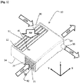
- [Fig. 1]
- est une vue schématique d'un corps d'échangeur de chaleur à double flux de gaz.
- [Fig. 2]
- est une vue schématique de l'échangeur de chaleur.
- [Fig. 3]
- est une vue schématique de coupe longitudinale de l'échangeur.
- [Fig. 1]
- is a schematic view of a gas bypass heat exchanger body.
- [Fig. 2]
- is a schematic view of the heat exchanger.
- [Fig. 3]
- is a schematic longitudinal sectional view of the exchanger.
Dans la description qui va suivre, des chiffres de référence identiques désignent des pièces identiques ou ayant des fonctions similaires.In the description which follows, identical reference numerals denote identical parts or having similar functions.
Pour faciliter la compréhension, la description qui suit concerne le refroidissement de gaz brulés recirculés et d'air compressé en amont de conduits d'admission d'un moteur thermique ici de véhicule automobile.To facilitate understanding, the following description relates to the cooling of recirculated burnt gases and compressed air upstream of the intake ducts of a heat engine, here of a motor vehicle.
Un moteur thermique ou à combustion interne (non représenté) de véhicule automobile comprend un circuit d'admission d'air dit frais capté généralement depuis la face avant du véhicule apte à acheminer cet air frais vers le moteur, notamment vers un répartiteur d'admission apte à distribuer l'air d'admission vers des conduits d'admission creusés dans une culasse et connectés à des chambres de combustion.A thermal or internal combustion engine (not shown) of a motor vehicle comprises a so-called fresh air intake circuit generally captured from the front face of the vehicle capable of conveying this fresh air to the engine, in particular to an intake distributor. capable of distributing the intake air to intake ducts hollowed out in a cylinder head and connected to combustion chambers.
Pour améliorer le rendement du moteur, il est connu d'augmenter la densité de l'air. L'air frais passe par un étage de compression qui peut être l'étage de compresseur d'un turbocompresseur du moteur. Il est également connu de disposer d'un compresseur électrique.To improve the efficiency of the engine, it is known to increase the density of the air. The fresh air passes through a compression stage which may be the compressor stage of an engine turbocharger. It is also known to have an electric compressor.
En sortie de l'étage de compression, la température de l'air a également augmenté, de l'ordre de 200°C, ce qui réduit l'efficacité du moteur. L'a ir en aval de l'étape de compression selon le sens de circulation de l'air doit être refroidi avant son admission dans le moteur.At the outlet of the compression stage, the air temperature has also increased, of the order of 200 ° C, which reduces the efficiency of the engine. The air downstream of the compression step in the direction of air flow must be cooled before it is admitted into the engine.
L'air doit alors passer par une étape de refroidissement qui est formée généralement par un échangeur de chaleur de type gaz-liquide de refroidissement. Ledit échangeur est connu sous le nom anglais de « Precooler » pour refroidisseur amont. Le liquide de refroidissement est à base d'eau qui circule dans un circuit de refroidissement du moteur grâce à une pompe à liquide de refroidissement.The air must then pass through a cooling step which is generally formed by a heat exchanger of the gas-cooling liquid type. Said exchanger is known under the English name of “Precooler” for an upstream cooler. The coolant is water-based which circulates in an engine cooling circuit by means of a coolant pump.
Parallèlement, pour réduire les émissions de polluants, il est connu de ramener des gaz brulés vers l'admission du moteur. Lesdits gaz brulés sont issus de la combustion dans la chambre de combustion du moteur. Ils sont captés dans un circuit d'échappement et acheminés vers l'admission du moteur notamment vers les conduits d'admission du moteur par un circuit de recirculation des gaz brulés.At the same time, to reduce pollutant emissions, it is known practice to return burnt gases to the engine intake. Said burnt gases result from the combustion in the combustion chamber of the engine. They are captured in an exhaust circuit and routed to the intake of the engine, in particular to the intake ducts of the engine, via a burnt gas recirculation circuit.
Les gaz ici sont des gaz recirculés haute pression captés au niveau d'un dispositif de collecte des gaz d'échappement. Lesdits gaz sont connus sous le nom de gaz « EGR » en anglais. On nommera par la suite lesdits gaz EGR par gaz recirculés.The gases here are high pressure recirculated gases captured at an exhaust gas collection device. Said gases are known under the name of “EGR” gas in English. Said EGR gases will be referred to below as recirculated gases.
Les gaz recirculés sont à haute température, de l'ordre de 700'C. Ils nécessitent d'être refroidis avant l'admission dans le moteur. Le circuit des gaz recirculés passe également par un échangeur de chaleur de type gaz/liquide de refroidissement.The recirculated gases are at high temperature, of the order of 700 ° C. They need to be cooled before admission to the engine. The recirculated gas circuit also passes through a heat exchanger of the gas / coolant type.
Pour réduire l'encombrement de l'ensemble comprenant le moteur avec les dispositifs de fonctionnement du moteur parmi lesquels les échangeurs de chaleur, on peut assembler l'échangeur de chaleur pour l'air frais compressé avec l'échangeur de chaleur pour les gaz recirculés. On obtient un système de refroidissement 100 de gaz à l'admission du moteur comprenant un échangeur double flux 10. Les entrées d'air compressé et de gaz recirculés sont par exemple agencées sur une paroi du carter de l'échangeur double flux tournée vers la face d'échappement du moteur tandis que les sorties sont tournées vers la face d'admission du moteur.To reduce the size of the assembly comprising the engine with the engine operating devices including the heat exchangers, the heat exchanger for the fresh compressed air can be assembled with the heat exchanger for the recirculated gases. . A gas cooling system 100 is obtained at the intake of the engine comprising a dual-
Cependant, les températures respectives de l'air compressé et des gaz recirculés sont très différentes ce qui entraine des problèmes de dilatation différentielles entre les deux échangeurs assemblés et plus clairement des parois du carter de l'échangeur double-flux. En effet, la différence importante de température entre les gaz recirculés et l'air d'admission peut entrainer de fortes contraintes thermomécaniques qui mettent en danger la tenue de l'échangeur et notamment du carter de l'échangeur. Par la suite, les parois de l'échangeur sont les parois du carter de l'échangeur.However, the respective temperatures of the compressed air and of the recirculated gases are very different, which causes differential expansion problems between the two assembled exchangers and more clearly the walls of the casing of the double-flow exchanger. Indeed, the significant difference in temperature between the recirculated gases and the intake air can lead to strong thermomechanical stresses which endanger the behavior of the exchanger and in particular of the exchanger casing. Subsequently, the walls of the exchanger are the walls of the casing of the exchanger.
Selon la
Le flux d'air compressé traverse l'échangeur selon un axe rectiligne Xa entre la première paroi d'entrée 12 et la première paroi de sortie 14 d'air de l'échangeur air-liquide de refroidissement. Les premières parois d'entrée 12 et de sortie 14 d'air sont symétriques par rapport à un plan médian orthogonal à l'axe Xa.The compressed air flow passes through the exchanger along a rectilinear axis Xa between the
De même, Le flux de gaz recirculés traverse l'échangeur selon un axe rectiligne Xg entre la deuxième paroi d'entrée 22 et la deuxième paroi de sortie 24 de l'échangeur gaz recirculés-liquide de refroidissement. Les deuxièmes parois d'entrée 22 et de sortie 24 sont symétriques par rapport à un plan médian orthogonal à l'axe Xg.Likewise, the flow of recirculated gas passes through the exchanger along a rectilinear axis Xg between the
Selon l'invention et de manière préférentielle, les axes d'écoulement d'air compressé Xa et de gaz recirculés Xg sont sensiblement orthogonaux pour présenter un moindre encombrement avec une simplicité de d'assemblage avec d'autres composants du moteur. Toutefois, l'axe d'écoulement d'air compressé peut être en biais par rapport à l'axe d'écoulement des recirculés pour faciliter la fixation de l'échangeur avec le moteur et réduire l'encombrement de l'ensemble.According to the invention and preferably, the axes of compressed air flow Xa and recirculated gas Xg are substantially orthogonal in order to present a smaller bulk with ease of assembly with other components of the engine. However, the axis compressed air flow can be angled with respect to the flow axis of the recirculated to facilitate the attachment of the exchanger with the engine and reduce the size of the assembly.
Comme représenté par la
La section de passage aval selon le sens d'écoulement de l'air, de la corne 13 fixée est sensiblement égale à la section de passage de l'échangeur de chaleur air-eau. En effet, la section de passage aval de la corne d'entrée 13 est la plus importante possible. Elle est sensiblement égale voire légèrement supérieure à la section de passage de l'échangeur air compressé-liquide de refroidissement.The downstream passage section in the direction of air flow of the fixed
On entend par section de passage de l'échangeur la section transversale de la chambre d'échangeur, orthogonale à l'axe de la direction du flux Xa d'air compressé.The term “heat exchanger passage section” is understood to mean the cross section of the exchanger chamber, orthogonal to the axis of the direction of the flow Xa of compressed air.
La corne de sortie 15 est sensiblement identique à la corne d'entrée. La section de passage amont de la corne de sortie 15 est donc égale à la section de passage de l'échangeur de chaleur air compressé-liquide de refroidissement.The
De manière préférentielle, le circuit de recirculation des gaz brulés est également raccordé par une deuxième corne d'entrée 23 fixée à la deuxième paroi d'entrée 22 de l'échangeur et par une corne de sortie 25 à une deuxième paroi de sortie 24 en vis-à-vis de la deuxième paroi d'entrée 22. La deuxième paroi d'entrée 22 est parallèle à la deuxième paroi de sortie 24. Les deuxièmes parois d'entrée 22 et de sortie 24 sont donc orthogonales aux premières parois d'entrée 12 et de sortie 14.Preferably, the burnt gas recirculation circuit is also connected by a
La section de passage aval de la deuxième corne d'entrée 23 fixée à l'échangeur est sensiblement égale à la section de passage de l'échangeur de chaleur gaz recirculés-liquide de refroidissement. La section de passage aval de la deuxième corne d'entrée 23 est la plus importante possible. Elle est sensiblement égale à la section de passage de l'échangeur gaz recirculés-liquide de refroidissement, voire légèrement supérieure. On entend par section de passage de l'échangeur la section transversale par rapport au sens d'écoulement des gaz ou de l'air, de la chambre d'échangeur de chaleur ici la chambre d'échange de chaleur entre les gaz recirculés et le liquide de refroidissement, orthogonale à l'axe Xg de la direction du flux de gaz recirculés.The downstream passage section of the
Le circuit de liquide de refroidissement est connecté à l'échangeur par des embouts d'entrée 32 et de sortie 33 de liquide de refroidissement qui s'étendent respectivement depuis une paroi d'entrée d'eau 31 et une paroi de sortie d'eau 34 de l'échangeur. L'entrée de liquide 30 et la sortie de liquide 35 définies par lesdits embouts sont agencées à une extrémité des parois d'entrée 31 et de sortie 34 pour obtenir une longueur de parcours du liquide de refroidissement la plus importante possible.The cooling liquid circuit is connected to the exchanger by cooling
De manière préférentielle, la paroi d'entrée d'eau 31 est distincte de la paroi de sortie d'eau 34. En effet, le parcours de l'eau dans le l'échangeur ne revient pas en arrière au risque d'altérer l'efficacité de l'échangeur, comme représenté par la
Le circuit de liquide de refroidissement suit un parcours dans l'échangeur 10 selon deux branches de refroidissement parallèles 38,39 et sensiblement symétriques par rapport à une paroi de séparation médiane plane 36 parallèle aux parois d'entrée 31 et de sortie 34 d'eau. L'échangeur 10 comprend ainsi deux chambres d'eau 41 et 42 pour refroidir individuellement l'air compressé et les gaz recirculés.The cooling liquid circuit follows a path in the
Dans les deux chambres d'eau 41,42 sont logés des conduits tubulaires 43,44 de section transversale oblongue pour conduire respectivement l'air compressé et les gaz recirculés entre les parois d'entrée 12,22 et de sortie 14,24.In the two
Les tubes guidant l'air et les gaz recirculés sont placés perpendiculairement. Ainsi, leurs dilatations respectives sous l'effet de la chaleur ne s'effectuent pas dans la même direction. Le carter peut donc se déformer de façon indépendante pour s'adapter à la variation de longueur des tubes dans chaque direction.The tubes guiding the air and the recirculated gases are placed perpendicularly. Thus, their respective expansions under the effect of heat do not take place in the same direction. The casing can therefore be deformed independently to adapt to the variation in length of the tubes in each direction.
De manière préférentielle, les volumes des deux chambres 41,42 de l'échangeur sont sensiblement égales.Preferably, the volumes of the two
De manière préférentielle, les deux branches 38,39 de refroidissement et de circulation du liquide de refroidissement à l'intérieur l'échangeur sont séparées par la paroi médiane de séparation 36.Preferably, the two
La paroi de séparation 36 comprend une ouverture 37 permettant la communication entre les deux chambres 41,42. Ladite ouverture 37 est percée dans la paroi de séparation de façon diamétralement opposée à l'entrée de liquide 30 pour permettre une longueur d'échange optimale, la plus longue possible. Ladite ouverture 37 est également agencée sensiblement diamétralement opposée à la sortie de fluide 35.The
De manière préférentielle, l'entrée de liquide de refroidissement 30 débouche dans la première chambre 41 de refroidissement dédiée aux échanges de chaleur avec l'air compressé. Selon les
Le liquide de refroidissement passe en premier dans la chambre de refroidissement 41 de l'air compressé, se charge en chaleur et sa température augmente avant de rejoindre la seconde chambre de refroidissement 42 pour refroidir les gaz recirculés.The cooling liquid first passes into the cooling
Les échanges de chaleur du liquide avec l'air compressé et les gaz recirculés s'effectuent en série pour favoriser le refroidissement de l'air compressé à l'admission.The heat exchanges of the liquid with the compressed air and the recirculated gases take place in series to promote the cooling of the compressed air at the intake.
De plus, la différence de température entre le liquide de refroidissement et les gaz recirculés est moindre et peut éviter la formation de condensats dans les tubes.In addition, the temperature difference between the coolant and the recirculated gases is less and can prevent the formation of condensate in the tubes.
Le parcours du liquide de refroidissement dans les chambres 41,42 est dirigé selon un axe sensiblement parallèle à la paroi médiane de séparation 36 dans un premier sens depuis l'entrée d'eau 30 vers l'ouverture 37, puis selon un second sens opposé depuis l'ouverture 37 vers la sortie d'eau 35 formant un parcours avec un profil de U à l'intérieur de l'échangeur 10 comme représenté en
L'axe des conduits tubulaires de gaz recirculés est parallèle à la paroi médiane de séparation et à l'axe de circulation d'eau dans la seconde chambre 42. L'axe de circulation du liquide de refroidissement sensiblement parallèle à l'axe Xg des conduits tubulaires de circulation des gaz recirculés permet d'éviter des phénomènes d'ébullition de l'eau.The axis of the tubular conduits of recirculated gas is parallel to the median separation wall and to the axis of water circulation in the
L'échangeur à double flux 10 pour refroidir l'air compressé et les gaz recirculés est compact de par l'assemblage des deux échangeurs, en assurant les contraintes thermomécaniques liées aux différences de températures entre les deux flux de d'air et de gaz, par un assemblage astucieux présentant des axes de circulation des flux orthogonaux. Ainsi, les dilatations respectives des parois de l'échangeur sous l'effet de la chaleur ne s'effectuent pas dans la même direction. Le carter de l'échangeur peut donc se déformer de façon indépendante pour s'adapter à la variation de longueur des conduits tubulaires d'air compressé 43 et de gaz recirculés 44 dans chacune des deux directions.The double-
Comme il va de soi, l'invention ne se limite pas aux seules formes d'exécution de cette prise, décrites ci-dessus à titre d'exemples, elle en embrasse au contraire toutes les variantes.As goes without saying, the invention is not limited to the only embodiments of this plug, described above by way of examples, it embraces on the contrary all the variants thereof.
Par exemple, le flux de circulation des gaz recirculés peut être dans le même sens que celui du liquide de refroidissement ou en sens contraire.For example, the circulation flow of the recirculated gases can be in the same direction as that of the coolant or in the opposite direction.
L'échangeur de chaleur selon l'invention peut concerner un autre domaine que l'automobile, pour refroidir deux flux de gaz à des températures différentes.The heat exchanger according to the invention can relate to a field other than the automobile, to cool two gas streams at different temperatures.
Claims (14)
caractérisé en ce que l'échangeur (10) comprend une chambre de refroidissement pour les gaz (42) accolée et communiquant avec une chambre de refroidissement pour l'air compressé (41) dans lesquelles l'axe du flux de gaz (Xg) est sensiblement orthogonal à l'axe du flux d'air compressé (Xa).Gas and air cooling system (100) comprising a double-flow heat exchanger (10) traversed by the gases along a first axis and the compressed air along a second axis,
characterized in that the exchanger (10) comprises a cooling chamber for the gases (42) contiguous and communicating with a cooling chamber for the compressed air (41) in which the axis of the gas flow (Xg) is substantially orthogonal to the axis of the compressed air flow (Xa).
Applications Claiming Priority (1)
| Application Number | Priority Date | Filing Date | Title |
|---|---|---|---|
| FR1914274A FR3111692B1 (en) | 2019-12-12 | 2019-12-12 | Double exchanger with orthogonal gas flows |
Publications (1)
| Publication Number | Publication Date |
|---|---|
| EP3835701A1 true EP3835701A1 (en) | 2021-06-16 |
Family
ID=69700160
Family Applications (1)
| Application Number | Title | Priority Date | Filing Date |
|---|---|---|---|
| EP20212535.7A Pending EP3835701A1 (en) | 2019-12-12 | 2020-12-08 | Double heat exchanger with orthogonal gas flow |
Country Status (2)
| Country | Link |
|---|---|
| EP (1) | EP3835701A1 (en) |
| FR (1) | FR3111692B1 (en) |
Citations (7)
| Publication number | Priority date | Publication date | Assignee | Title |
|---|---|---|---|---|
| DE102007009354A1 (en) * | 2007-02-23 | 2008-09-04 | Mahle International Gmbh | Fresh gas module for a fresh gas system |
| FR2917124A1 (en) * | 2007-06-08 | 2008-12-12 | Valeo Systemes Thermiques | Internal combustion engine cooling circuit for motor vehicle, has charge air cooler and recirculated exhaust gas coolers regrouped in same cooling module, and respectively having covers that are mutually fixed by soldering |
| US20110139133A1 (en) | 2010-05-28 | 2011-06-16 | Ford Global Technologies, Llc | Cooled egr system for coolant heating during cold engine start |
| DE102011013029A1 (en) * | 2010-03-15 | 2011-09-15 | Denso Corporation | Exhaust gas recirculation device for combustion engine, comprises turbocharger, which is set in inlet system for sucking air under pressure, and intercooler for cooling intake air by heat exchange with coolant circulated through intercooler |
| DE102014110046A1 (en) * | 2013-12-16 | 2015-06-18 | Hyundai Motor Company | Cooling system for a turbocharged diesel engine |
| FR3049312A1 (en) * | 2016-03-25 | 2017-09-29 | Renault Sas | DEVICE AND COOLING SYSTEM FOR GAS SUPPLYING A COMBUSTION ENGINE |
| FR3079880A1 (en) | 2018-04-05 | 2019-10-11 | Renault S.A.S | DUAL FLOW ADMISSION MODULE |
-
2019
- 2019-12-12 FR FR1914274A patent/FR3111692B1/en active Active
-
2020
- 2020-12-08 EP EP20212535.7A patent/EP3835701A1/en active Pending
Patent Citations (7)
| Publication number | Priority date | Publication date | Assignee | Title |
|---|---|---|---|---|
| DE102007009354A1 (en) * | 2007-02-23 | 2008-09-04 | Mahle International Gmbh | Fresh gas module for a fresh gas system |
| FR2917124A1 (en) * | 2007-06-08 | 2008-12-12 | Valeo Systemes Thermiques | Internal combustion engine cooling circuit for motor vehicle, has charge air cooler and recirculated exhaust gas coolers regrouped in same cooling module, and respectively having covers that are mutually fixed by soldering |
| DE102011013029A1 (en) * | 2010-03-15 | 2011-09-15 | Denso Corporation | Exhaust gas recirculation device for combustion engine, comprises turbocharger, which is set in inlet system for sucking air under pressure, and intercooler for cooling intake air by heat exchange with coolant circulated through intercooler |
| US20110139133A1 (en) | 2010-05-28 | 2011-06-16 | Ford Global Technologies, Llc | Cooled egr system for coolant heating during cold engine start |
| DE102014110046A1 (en) * | 2013-12-16 | 2015-06-18 | Hyundai Motor Company | Cooling system for a turbocharged diesel engine |
| FR3049312A1 (en) * | 2016-03-25 | 2017-09-29 | Renault Sas | DEVICE AND COOLING SYSTEM FOR GAS SUPPLYING A COMBUSTION ENGINE |
| FR3079880A1 (en) | 2018-04-05 | 2019-10-11 | Renault S.A.S | DUAL FLOW ADMISSION MODULE |
Also Published As
| Publication number | Publication date |
|---|---|
| FR3111692A1 (en) | 2021-12-24 |
| FR3111692B1 (en) | 2022-10-14 |
Similar Documents
| Publication | Publication Date | Title |
|---|---|---|
| EP1620637B1 (en) | System for cooling a piece of equipment to a low temperature, such as a piece of motor vehicle equipment, and associated heat exchangers | |
| EP2066884B1 (en) | Cooling circuit for the thermal engine of an automotive vehicle | |
| US20100132346A1 (en) | Exhaust-gas cooler for an internal combustion engine | |
| FR2901849A1 (en) | COOLER FOR RECYCLING EXHAUST GAS WITH TWO BUCKLES OF COOLING FLUID | |
| FR2922962A1 (en) | Intake air flow condensate e.g. acid condensate, collecting and evacuating device for motor vehicle, has tube including end arranged in receptacle and another end that is opened near diaphragm at level where air flow is accelerated | |
| WO2009068504A1 (en) | Pollution control and heating device and method for a motor vehicle | |
| WO2012062715A1 (en) | Gas distribution manifold and corresponding gas intake module | |
| US20070227141A1 (en) | Multi-stage jacket water aftercooler system | |
| WO2003102396A1 (en) | Heat exchange module for enclosing a motor vehicle engine | |
| WO2007031637A1 (en) | Heat exchange module for controlling temperature of intake gases in a two-bank internal combustion engine for a motor vehicle | |
| FR3079880A1 (en) | DUAL FLOW ADMISSION MODULE | |
| FR3000140A1 (en) | THERMAL MANAGEMENT DEVICE FOR THE INTAKE AIR OF A MOTOR AND ASSOCIATED THERMAL MANAGEMENT METHOD | |
| EP1963657B1 (en) | Device for cooling intake air and recycled exhaust gases | |
| EP3835701A1 (en) | Double heat exchanger with orthogonal gas flow | |
| FR2917124A1 (en) | Internal combustion engine cooling circuit for motor vehicle, has charge air cooler and recirculated exhaust gas coolers regrouped in same cooling module, and respectively having covers that are mutually fixed by soldering | |
| EP3551953A1 (en) | Heat exchanger, in particular a charge air heat exchanger for a motor vehicle | |
| EP2469067B1 (en) | Casing for intake module, in particular for the intake module of an automobile combustion engine, and intake module including such a casing | |
| EP3922825A1 (en) | Cooling circuit for a dual-flow module | |
| EP2469066B1 (en) | Manifold for distributing gas in the intake ducts of a heat engine of an automobile and intake module provided with such a manifold | |
| WO2019233669A1 (en) | Intake manifold for heat engine with optimized recirculated gas mixing device | |
| FR3120398A1 (en) | Trapezoidal section tube exchanger device | |
| FR2983533A1 (en) | Device for thermal regulation of intake air of e.g. diesel engine and recirculated exhaust gas emitted by engine in car, has heat exchanger whose inlet is in fluid communication with housing inlet and outlet of another heat exchanger | |
| EP2469068A1 (en) | Casing for intake module, in particular for the intake module of an automobile combustion engine, and intake module including such a casing | |
| FR2922960A1 (en) | Blow-by gas reinjection system for e.g. petrol engine of motor vehicle, has exhaust gas recuperating circuit emerging from air intake circuit of engine, and blow-by gas recuperating circuit connected in exhaust gas recuperating circuit | |
| FR2929340A1 (en) | Low-temperature cooling circuit for internal combustion heat engine in motor vehicle, has recirculated exhaust gas cooling assembly connected in series with supply gas cooling assembly whose coolers are connected in parallel |
Legal Events
| Date | Code | Title | Description |
|---|---|---|---|
| PUAI | Public reference made under article 153(3) epc to a published international application that has entered the european phase |
Free format text: ORIGINAL CODE: 0009012 |
|
| STAA | Information on the status of an ep patent application or granted ep patent |
Free format text: STATUS: THE APPLICATION HAS BEEN PUBLISHED |
|
| AK | Designated contracting states |
Kind code of ref document: A1 Designated state(s): AL AT BE BG CH CY CZ DE DK EE ES FI FR GB GR HR HU IE IS IT LI LT LU LV MC MK MT NL NO PL PT RO RS SE SI SK SM TR |
|
| STAA | Information on the status of an ep patent application or granted ep patent |
Free format text: STATUS: REQUEST FOR EXAMINATION WAS MADE |
|
| 17P | Request for examination filed |
Effective date: 20210701 |
|
| RBV | Designated contracting states (corrected) |
Designated state(s): AL AT BE BG CH CY CZ DE DK EE ES FI FR GB GR HR HU IE IS IT LI LT LU LV MC MK MT NL NO PL PT RO RS SE SI SK SM TR |
|
| RAP3 | Party data changed (applicant data changed or rights of an application transferred) |
Owner name: RENAULT S.A.S |
|
| RAP3 | Party data changed (applicant data changed or rights of an application transferred) |
Owner name: RENAULT S.A.S |
|
| P01 | Opt-out of the competence of the unified patent court (upc) registered |
Effective date: 20230608 |
|
| RAP1 | Party data changed (applicant data changed or rights of an application transferred) |
Owner name: NEW H POWERTRAIN HOLDING, S.L.U. |