EP3835667B1 - Method for controlling a heating system and control device for same - Google Patents
Method for controlling a heating system and control device for same Download PDFInfo
- Publication number
- EP3835667B1 EP3835667B1 EP20207398.7A EP20207398A EP3835667B1 EP 3835667 B1 EP3835667 B1 EP 3835667B1 EP 20207398 A EP20207398 A EP 20207398A EP 3835667 B1 EP3835667 B1 EP 3835667B1
- Authority
- EP
- European Patent Office
- Prior art keywords
- heating
- temperature
- heating circuit
- hot water
- heat generator
- Prior art date
- Legal status (The legal status is an assumption and is not a legal conclusion. Google has not performed a legal analysis and makes no representation as to the accuracy of the status listed.)
- Active
Links
- 238000010438 heat treatment Methods 0.000 title claims description 296
- 238000000034 method Methods 0.000 title claims description 42
- XLYOFNOQVPJJNP-UHFFFAOYSA-N water Substances O XLYOFNOQVPJJNP-UHFFFAOYSA-N 0.000 claims description 155
- 230000009467 reduction Effects 0.000 claims description 10
- 230000003247 decreasing effect Effects 0.000 claims 1
- 238000002360 preparation method Methods 0.000 description 83
- 230000008569 process Effects 0.000 description 7
- 235000006506 Brasenia schreberi Nutrition 0.000 description 5
- 238000001816 cooling Methods 0.000 description 5
- 230000033228 biological regulation Effects 0.000 description 3
- 238000005516 engineering process Methods 0.000 description 3
- 230000020169 heat generation Effects 0.000 description 3
- 230000004913 activation Effects 0.000 description 1
- 230000005540 biological transmission Effects 0.000 description 1
- 238000004891 communication Methods 0.000 description 1
- 230000007423 decrease Effects 0.000 description 1
- 238000001514 detection method Methods 0.000 description 1
- 230000035622 drinking Effects 0.000 description 1
- 239000008236 heating water Substances 0.000 description 1
- 230000007774 longterm Effects 0.000 description 1
- 238000002156 mixing Methods 0.000 description 1
- 238000005457 optimization Methods 0.000 description 1
- 239000008188 pellet Substances 0.000 description 1
- 238000003303 reheating Methods 0.000 description 1
- 238000009420 retrofitting Methods 0.000 description 1
- 238000010079 rubber tapping Methods 0.000 description 1
- 230000008054 signal transmission Effects 0.000 description 1
- 238000004088 simulation Methods 0.000 description 1
- 230000036578 sleeping time Effects 0.000 description 1
- 230000007704 transition Effects 0.000 description 1
Images


Classifications
-
- F—MECHANICAL ENGINEERING; LIGHTING; HEATING; WEAPONS; BLASTING
- F24—HEATING; RANGES; VENTILATING
- F24D—DOMESTIC- OR SPACE-HEATING SYSTEMS, e.g. CENTRAL HEATING SYSTEMS; DOMESTIC HOT-WATER SUPPLY SYSTEMS; ELEMENTS OR COMPONENTS THEREFOR
- F24D19/00—Details
- F24D19/10—Arrangement or mounting of control or safety devices
- F24D19/1006—Arrangement or mounting of control or safety devices for water heating systems
- F24D19/1066—Arrangement or mounting of control or safety devices for water heating systems for the combination of central heating and domestic hot water
- F24D19/1069—Arrangement or mounting of control or safety devices for water heating systems for the combination of central heating and domestic hot water regulation in function of the temperature of the domestic hot water
-
- F—MECHANICAL ENGINEERING; LIGHTING; HEATING; WEAPONS; BLASTING
- F24—HEATING; RANGES; VENTILATING
- F24D—DOMESTIC- OR SPACE-HEATING SYSTEMS, e.g. CENTRAL HEATING SYSTEMS; DOMESTIC HOT-WATER SUPPLY SYSTEMS; ELEMENTS OR COMPONENTS THEREFOR
- F24D3/00—Hot-water central heating systems
- F24D3/08—Hot-water central heating systems in combination with systems for domestic hot-water supply
-
- F—MECHANICAL ENGINEERING; LIGHTING; HEATING; WEAPONS; BLASTING
- F24—HEATING; RANGES; VENTILATING
- F24H—FLUID HEATERS, e.g. WATER OR AIR HEATERS, HAVING HEAT-GENERATING MEANS, e.g. HEAT PUMPS, IN GENERAL
- F24H1/00—Water heaters, e.g. boilers, continuous-flow heaters or water-storage heaters
- F24H1/10—Continuous-flow heaters, i.e. heaters in which heat is generated only while the water is flowing, e.g. with direct contact of the water with the heating medium
-
- F—MECHANICAL ENGINEERING; LIGHTING; HEATING; WEAPONS; BLASTING
- F24—HEATING; RANGES; VENTILATING
- F24H—FLUID HEATERS, e.g. WATER OR AIR HEATERS, HAVING HEAT-GENERATING MEANS, e.g. HEAT PUMPS, IN GENERAL
- F24H1/00—Water heaters, e.g. boilers, continuous-flow heaters or water-storage heaters
- F24H1/48—Water heaters for central heating incorporating heaters for domestic water
- F24H1/52—Water heaters for central heating incorporating heaters for domestic water incorporating heat exchangers for domestic water
-
- F—MECHANICAL ENGINEERING; LIGHTING; HEATING; WEAPONS; BLASTING
- F24—HEATING; RANGES; VENTILATING
- F24H—FLUID HEATERS, e.g. WATER OR AIR HEATERS, HAVING HEAT-GENERATING MEANS, e.g. HEAT PUMPS, IN GENERAL
- F24H15/00—Control of fluid heaters
- F24H15/10—Control of fluid heaters characterised by the purpose of the control
- F24H15/156—Reducing the quantity of energy consumed; Increasing efficiency
-
- F—MECHANICAL ENGINEERING; LIGHTING; HEATING; WEAPONS; BLASTING
- F24—HEATING; RANGES; VENTILATING
- F24H—FLUID HEATERS, e.g. WATER OR AIR HEATERS, HAVING HEAT-GENERATING MEANS, e.g. HEAT PUMPS, IN GENERAL
- F24H15/00—Control of fluid heaters
- F24H15/10—Control of fluid heaters characterised by the purpose of the control
- F24H15/174—Supplying heated water with desired temperature or desired range of temperature
-
- F—MECHANICAL ENGINEERING; LIGHTING; HEATING; WEAPONS; BLASTING
- F24—HEATING; RANGES; VENTILATING
- F24H—FLUID HEATERS, e.g. WATER OR AIR HEATERS, HAVING HEAT-GENERATING MEANS, e.g. HEAT PUMPS, IN GENERAL
- F24H15/00—Control of fluid heaters
- F24H15/20—Control of fluid heaters characterised by control inputs
- F24H15/212—Temperature of the water
- F24H15/219—Temperature of the water after heating
-
- F—MECHANICAL ENGINEERING; LIGHTING; HEATING; WEAPONS; BLASTING
- F24—HEATING; RANGES; VENTILATING
- F24H—FLUID HEATERS, e.g. WATER OR AIR HEATERS, HAVING HEAT-GENERATING MEANS, e.g. HEAT PUMPS, IN GENERAL
- F24H15/00—Control of fluid heaters
- F24H15/30—Control of fluid heaters characterised by control outputs; characterised by the components to be controlled
- F24H15/355—Control of heat-generating means in heaters
- F24H15/36—Control of heat-generating means in heaters of burners
-
- F—MECHANICAL ENGINEERING; LIGHTING; HEATING; WEAPONS; BLASTING
- F24—HEATING; RANGES; VENTILATING
- F24H—FLUID HEATERS, e.g. WATER OR AIR HEATERS, HAVING HEAT-GENERATING MEANS, e.g. HEAT PUMPS, IN GENERAL
- F24H15/00—Control of fluid heaters
- F24H15/40—Control of fluid heaters characterised by the type of controllers
- F24H15/414—Control of fluid heaters characterised by the type of controllers using electronic processing, e.g. computer-based
- F24H15/45—Control of fluid heaters characterised by the type of controllers using electronic processing, e.g. computer-based remotely accessible
-
- F—MECHANICAL ENGINEERING; LIGHTING; HEATING; WEAPONS; BLASTING
- F24—HEATING; RANGES; VENTILATING
- F24H—FLUID HEATERS, e.g. WATER OR AIR HEATERS, HAVING HEAT-GENERATING MEANS, e.g. HEAT PUMPS, IN GENERAL
- F24H9/00—Details
- F24H9/20—Arrangement or mounting of control or safety devices
- F24H9/2007—Arrangement or mounting of control or safety devices for water heaters
-
- F—MECHANICAL ENGINEERING; LIGHTING; HEATING; WEAPONS; BLASTING
- F24—HEATING; RANGES; VENTILATING
- F24D—DOMESTIC- OR SPACE-HEATING SYSTEMS, e.g. CENTRAL HEATING SYSTEMS; DOMESTIC HOT-WATER SUPPLY SYSTEMS; ELEMENTS OR COMPONENTS THEREFOR
- F24D2220/00—Components of central heating installations excluding heat sources
- F24D2220/02—Fluid distribution means
- F24D2220/0235—Three-way-valves
Definitions
- the invention relates to a method for controlling a heating system, preferably with a condensing boiler as the heat generator, with at least one heating circuit for heating the building and with hot water preparation for heating service water to a hot water target temperature.
- the heated service water can, for example, be stored in a hot water storage tank.
- a heat generator flow temperature is selected to be greater than or equal to the heating circuit target temperature, and a mixer is provided for setting a heating circuit target temperature, i.e. for setting the actual heating circuit temperature in accordance with the heating circuit target temperature.
- the invention also relates to a control device set up to carry out the method described below or parts thereof.
- the heat source flow temperature in heating mode is selected so that it exceeds the heating circuit target temperature just far enough for a heat transfer medium circulating in the heating circuit to be heated to the heating circuit target temperature.
- the heat generator typically reheats when a heating controller determines that the actual temperature of the heating circuit falls below the target temperature of the heating circuit by an adjustable amount and the actual temperature of the heating circuit should be increased, but the heat generator flow temperature is too low to generate the actual temperature of the heating circuit .
- the heat generator flow temperature can be selected in such a way that the condensing boiler heats evenly over the long term and provides just such a heat output that the actual heating circuit temperature can be maintained in all heating circuits. If the heat generator flow temperature exceeds the heating circuit setpoint temperature by more than a parameterizable value, the heat generator switches off until it has to be reheated as described above in order to maintain the heating circuit setpoint temperature.
- the mixer mixes the heat transfer medium from the heat generator (with the heat generator flow temperature) if necessary with the heat transfer medium from the heating return (which has a lower temperature) in order to set the heating circuit setpoint temperature as the actual heating circuit temperature. This is usually done by a controller that monitors the deviation of the actual heating circuit temperature from the heating circuit target temperature and uses a variable to act on the mixer in the heating circuit in such a way that the actual heating circuit temperature corresponds to the target heating circuit temperature.
- the heat generator heats a heat transfer medium to a heat transfer medium flow temperature and delivers it to the building heating and hot water preparation via a flow.
- the heat transfer medium from the building heating (i.e. from the heating circuits) and from the hot water preparation flows via a return flow back to the heat generator, which heats up the heat transfer medium again, after the heat energy has been released in the systems (building heating, hot water supply).
- the efficiency of a condensing boiler preferred according to the invention is essentially determined by the heat generator return flow temperature of the heat transfer medium that is fed to the heat generator for heating.
- the return is made up of the building heating return (all heating circuits) and the hot water generation return (of the hot water storage tank loading circuit).
- the return temperature of the heat transfer medium returned to the heat generator should be as low as possible, preferably in the range between 20°C and 40°C and in any case not exceed the condensing limit temperature of about 57°C. Above this temperature, the efficiency gain of the condensing technology is only small. It is therefore advantageous to select the heating circuit flow temperature (heating circuit setpoint temperature) in such a way that the thermal output released in the heating circuit cools the heat transfer medium down to near room temperature. The condensing boiler then generates just the heat output required in heating mode and runs continuously with a high degree of efficiency.
- the return temperature from the hot water preparation depends on the flow temperature and the flow rate in the charging circuit as well as the charging status and the design of any hot water storage tank.
- the return temperature from the hot water preparation is typically well above the return temperature of the heating circuit. The efficiency of the condensing boiler is therefore significantly lower during hot water preparation than in heating mode.
- a condensing boiler in the sense of this text is understood not only as a condensing boiler in the sense described above, the efficiency of which depends significantly on the return temperature of the heat carrier heated in the heat generator.
- a condensing boiler within the meaning of this text is generally understood to mean a heat generator that can be operated more efficiently in the heating mode of a building than in the hot water preparation, which often requires higher heat generator temperatures than the heating mode.
- Condensing boilers within the meaning of this text can be heat generators that generate heat locally by converting final energy (e.g. oil, gas, pellets) in a boiler, combined heat and power plant, heat pump or similar, or obtain heat from a district or local heating network.
- Heating systems with heating mode and hot water preparation are often operated with a hot water priority circuit.
- a hot water priority circuit is supported by every common heating regulation or heating control.
- the heat supply to the heating circuit is stopped while the service water is being heated during hot water preparation.
- the temperature of the heat generator (boiler temperature or heat generator flow temperature) is increased and the drinking or process water in the hot water storage tank is heated.
- an after-running phase of usually a few minutes is activated, in which the heat generator can transfer most of its residual heat to the hot water storage tank when it is switched off.
- the charging branch for hot water preparation is then switched off and the heating circuit switched on again for heating operation.
- a disadvantage of the hot water priority circuit is that the building heating or its heating circuit or heating circuits is not supplied with heat during the hot water preparation period. Depending on the size of the hot water storage tank and/or the hot water requirement in the building, this period of non-supply of the building heating with heat can be 20 to over 40 minutes.
- the heating pump is switched off during hot water preparation, which can be perceived by the occupants of the building as a failure of the heating system, especially if a cooled radiator is to be put into operation during this time.
- Other heating controllers close the mixer in the heating circuit, but allow a heating circuit pump to continue running. The heating circuit is then operated without heat supply. This also leads to severe cooling, but due to the perceptible flow of the heat transfer medium in the radiator, it is not directly perceived as a failure of the heating system.
- This disadvantage of room heating comfort can be remedied by deactivating the hot water priority circuit.
- the heating circuit is operated continuously, even during hot water preparation.
- this mode of operation has the disadvantage that the entire space heating energy, with which the heating circuit is supplied during hot water preparation, is generated at a less energy-efficient operating point of the heat generator.
- the heat generator is not operated in an energy-efficient manner during hot water preparation and during the transition from hot water preparation to heating operation.
- the DE 44 38 881 A1 discloses a heating system with a condensing boiler, heating circuits, a service water boiler and a service water circuit and a control device for this, which sets priority operation of the service water circuit or parallel operation of heating and service water circuits depending on the outside, room, boiler water and/or service water temperature.
- the U.S. 2018/120824 A1 relates to a similar heating system with a control unit that prompts a consumer to end hot water consumption if the heating mode has to be switched back on first.
- DE 43 13 277 C1 DE 197 01 823 A1
- EP 0 608 500 A1 and EP 3 492 828 A1 similar heating systems and methods for their operation for heating and/or hot water supply are described.
- the object of the invention is to increase the energy efficiency of a heating system with in particular a condensing boiler as a heat generator, building heating and hot water preparation in a simple manner.
- a method of the type mentioned at the outset provides in particular that during hot water preparation, in particular at the start of hot water preparation, a regular heating circuit target temperature in heating mode (also referred to as the target flow temperature of the heating circuit) is reduced by a configurable value and increased again after hot water preparation the regular heating circuit setpoint temperature of heating operation is reset.
- the regular heating circuit setpoint temperature (after reducing the heating circuit setpoint temperature during hot water preparation) is set again after hot water preparation.
- the regular heating circuit setpoint temperature can, for example, be taken from a heating curve or from another control and/or regulation system.
- the inventive method is also referred to as "soft priority circuit".
- Radiator heaters are particularly preferably provided in the heating circuit, in which case the method is particularly effective and offers the user a significant increase in comfort while at the same time optimizing the efficiency of the heat generation.
- the heating circuit setpoint temperature can be reduced before the heat generator flow temperature is increased during hot water preparation.
- the heating circuit setpoint temperature can preferably be reduced immediately before the heat generator flow temperature is increased.
- “directly” means that after the heating circuit target temperature has been reduced, the controller only waits for a period of time during which it closes the mixer fully or partially. After this positioning time, the heat generator flow temperature can be increased immediately. This is typically done as part of the hot water preparation, in which the hot water should be generated as quickly as possible and therefore the heat generator flow temperature is selected as high as possible; Heat source flow temperatures between 70°C and 90°C are often reached, e.g. around 80°C.
- the mixer After the positioning time, the mixer is usually closed first, since the actual heating circuit temperature is significantly higher than the (now reduced) heating circuit target temperature and there is therefore no heat requirement in the heating circuit. If the mixer is closed before the heat source flow temperature is increased, an additional surge of heat into the heating circuit is avoided.
- the heating circuit first cools down by the specified value before heat energy is supplied again (by opening the mixer to a suitable extent).
- the heating circuit setpoint temperature can be reduced as a "night setback control command" and thus analogous to a night setback, with which the heating circuit setpoint temperature is lowered during the usual sleeping times of the occupants or non-use times in office buildings.
- a temperature value for reducing the heating circuit setpoint temperature can also be specified as a parameter within the scope of the method proposed according to the invention, e.g. in the order of around -10 K to -15 K or a relative reduction in the heating circuit overtemperature from to about 25% the current heating circuit excess temperature.
- the excess temperature is the difference between the heating circuit flow temperature and the average building temperature.
- the duration of the reduction in the heating circuit setpoint temperature during hot water preparation is limited and the regular heating circuit setpoint temperature is set again at the latest after the duration has expired, even if the hot water preparation is not yet complete.
- This maximum duration can preferably be configured, ie it can be specified by the user. If this possibly parameterizable maximum duration, for example in the order of 45 minutes to 1 hour, is exceeded, the heating circuit target temperature (target flow temperature) is increased again to its regular value, which corresponds in particular to the heating curve, by this variant of the proposed method according to the invention. This prevents the building from being undersupplied or cooling down beyond the usual duration of hot water preparation if the hot water preparation should take an unusually long time.
- the duration of the reduction in the heating circuit setpoint temperature can be learned or determined from the usual duration of hot water preparation in the building by recording the duration of hot water preparation over a certain period of time, i.e. several cycles of hot water preparation, and determining an average duration , whereby the duration of the reduction of the heating circuit setpoint temperature is selected as a multiple of the determined average duration (of hot water preparation).
- the multiple can be determined by a factor that is an integer or rational number greater than 1, i.e., for example, 1.5 times the determined average duration.
- the controller is the start and end time of the hot water preparation known, so that the duration of hot water preparation can be determined by a simple time difference.
- the average duration in several hot water preparation cycles is particularly preferably determined over a specific period of time, which is preferably at least one day or several days up to one week. Determining the average duration in a week captures the typical habits of hot water consumption by users in different situations. This forms a statistically meaningful basis for determining the average duration of hot water preparation. This can be determined automatically by the system or the controller. For example, 1.5 times to 2 times the average duration can be selected as a multiple of the average duration in order to limit the duration of the reduction in the heating circuit setpoint temperature. In addition, an absolute maximum duration, for example 1 hour, can also be specified. This also prevents the building from cooling down too much during the cold season.
- the gain in efficiency in heating operation compared to hot water preparation with classic condensing boilers is only achieved if the temperature of the heat carrier returned to the heat generator in the return does not exceed the condensing value limit temperature already explained, it can be provided in a sensible optional embodiment of the proposed method that the The heating circuit return temperature is measured and the reduction in the heating circuit set temperature is returned (ie ended or reduced) if the heating circuit return temperature is above the condensing limit temperature.
- the increase in efficiency depends on the return temperature of the heat transfer medium in the heating circuit. If this temperature is above a calorific value limit temperature, which can be around 57° C., for example, the efficiency gain of the proposed method is only slight.
- the reduction in the heating circuit setpoint temperature proposed according to the invention can then be returned or reduced down to the value 0, at which the heating circuit setpoint temperature corresponds to the regular heating circuit setpoint temperature, as it is specified for example by a heating characteristic. In this case, the heat would not be generated more efficiently in heating mode than in hot water preparation.
- this also includes a control unit for controlling a heating system, preferably with a condensing boiler as the heat generator, with at least one heating circuit for heating the building and with hot water preparation for heating service water to a hot water target temperature, with the service water being stored in a hot water tank, for example of hot water preparation can be saved.
- the proposed control device has interfaces for controlling the heat generator, the at least one heating circuit and the hot water preparation, as well as a computing device that is set up to carry out the method described above or parts thereof.
- the computing device can be located both in the control unit on site (local) and, for example, in an IT cloud or a data center (remote). If the computing device is in the IT cloud or in a data center (e.g. in a central IT system), parameters for controlling the heat generator can be downloaded to the control unit, for example via a mobile data transmission interface.
- the control unit can be integrated into the control unit that is usually present in the heating system and can have internal interfaces for controlling the heat generator, the at least one heating circuit and the hot water preparation.
- the control unit can also be provided as a device separate from the heating system and can be connected to the control unit of the heating system via a control interface, for example a suitable bus or other interface via which the aforementioned interfaces can be implemented.
- control unit can carry out a flow temperature simulation and thus indirectly bring the existing control unit of the heating system to adjust the flow temperature.
- temperature sensors for detecting the heat generator flow temperature, the heat generator return temperature, the heating circuit flow temperature, the heating circuit return temperature and/or the actual hot water temperature can be connected or can be connected to the interfaces of the control unit. This enables the control device to carry out the method proposed according to the invention in a simple and precise manner.
- a further refinement of the invention can take place in that the control device controls a mixer of the heating system directly.
- the control signal from the original heating controller can be recorded by the control unit, interpreted and forwarded to the mixer either unchanged or manipulated.
- An optimized control of the mixer can be based on measured temperature values or can be achieved with knowledge of the mixer runtime and mixer position.
- control unit 1 is shown according to an embodiment of the invention.
- the control device 1 is connected via interfaces 2, 3, 4, 5 to components of a heating system 100 of a building.
- a computing device (not shown) which is set up to carry out the method proposed according to the invention for controlling the heating system 100 .
- the computing device can be arranged in an IT cloud or in a computing center, in which case there is a communication unit (not shown) in control unit 1 instead of the computing device.
- the heating system 100 has a heat generator 101, preferably designed as a condensing boiler, a heating circuit 111 for heating the building and a water heater 121 for heating service water to a desired hot water temperature.
- the service water can be tapped by the users of the building.
- the water heater 121 also includes an in figure 1 water reservoir, not shown, in which the heated domestic water is stored.
- Interface 2 connects control unit 1 to heat generator 101.
- Interface 3 connects control unit 1 to hot water preparation 121.
- Interface 4 connects control unit 1 to heating circuit 111.
- Optional interface 5 connects control unit 1 to mixer 112 of heating circuit 111 Via the interface 5, the control device 1 can set the mixer 112 via the activation of the electrically operated mixer motor or servomotor and thus the heating circuit flow temperature ⁇ HZ VL affect directly.
- Control signals are output via interfaces 2, 3, 4, 5. This is in the figure 1 shown as a dashed line.
- the heating circuit 111 is connected to the heat generator flow 102 via a mixer 112 .
- the heat generator 101 outputs the heated heat transfer medium at a heat transfer medium flow temperature via the heat generator flow 102 ⁇ WE VL out of.
- the temperatures are in figure 1 represented by a labeled dot at the respective positions where they are measurable by a temperature sensor. These points can also represent temperature sensors, which can be queried by the controller 1, for example, via the interfaces 2, 3, 4 (and a signal transmission that is not shown).
- the heated heat transfer medium with the heat transfer medium flow temperature ⁇ WE VL is fed to a first input of the mixer 112 .
- a second input of the mixer 112 is connected to the heating circuit return 114 in order to cool the heat transfer medium from the heat generator flow 102 by adding the (cooled down) heat transfer medium from the heating circuit return 114 and in the heating circuit flow 113 one of the heating circuit set temperature ⁇ HZ should corresponding heating circuit flow temperature ⁇ HZ VL set.
- the heating circuit target temperature ⁇ HZ should not marked.
- the heating circuit 111 is in the heat transfer medium with the flow temperature ⁇ HZ VL Stored thermal energy is partially released via heat exchangers, preferably radiator heat exchangers (classic radiators).
- the heat transfer medium cools down to the return temperature ⁇ HZ RL away.
- the heat transfer medium is fed back to the heat generator 101 for reheating via the heat generator return 103 .
- the heat transfer medium is used at the heat transfer medium flow temperature ⁇ WE VL supplied to the hot water treatment 121, in which the heat carrier transfers the thermal energy via a heat exchanger to the hot water, which is usually stored in an insulated heat accumulator, not shown, and is available for tapping by the user. After the thermal energy has been released by the heat transfer medium to the process water, the heat transfer medium is fed back into the return 103 of the heat generator 101 via the hot water preparation return 122 . In the flow, the hot water preparation 121 is connected directly to the heat generator flow 102 .
- hot water preparation 121 is carried out in a so-called priority mode, in which mixer 112 of heating circuit 111 is closed, so that no heat is supplied to heating circuit 111 during hot water preparation 121.
- heating circuit 111 for the sake of clarity, only one heating circuit 111 is shown. However, more than one heating circuit 111 can also be provided in buildings; the plurality of heating circuits 111 are then connected to the heat generator flow 102 in a comparable manner, preferably via their own mixer 112 .
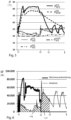
- the temperature profile in parallel operation of hot water preparation 121 and heating operation in the heating circuit 111 is in figure 3 shown.
- the heating system 100 is still in pure heating mode (left side of the time axis before time t1).
- the heat generator flow temperature ⁇ WE VL and the heating circuit flow temperature ⁇ HZ VL fall in unison from a temperature value ⁇ - in the example - greater than 50 °C to a temperature value of about - in the example - 45 °C, which is close to the heating circuit return temperature ⁇ HZ RL lies.
- the heating circuit target temperature ⁇ HZ VL is - in the example - at 50 °C.
- hot water preparation is also activated parallel to heating operation.
- the heat generator flow temperature is used for this ⁇ WE VL to - in the example - increased to about 85 ° C and fed to the heat transfer medium of hot water preparation 121. There it partially transfers its thermal energy to the process water and leaves the hot water preparation 121 with the heating water return temperature ⁇ ww RL , which is only slightly lower than the heat generator flow temperature ⁇ WE VL and is significantly higher than the heating circuit return temperature ⁇ HZ RL .
- the temperatures mentioned correspond to possible temperature values that can occur in typical systems.
- the invention is not intended to be limited to these temperature values, which those skilled in the art will adjust as needed.
- the heat generator flow temperature ⁇ WE VL is kept at the temperature level of a good 80 °C until time t2, at which the actual service water temperature ⁇ ww is the required domestic water target temperature ⁇ ww should is equivalent to. This temperature value is also only to be understood as an example. However, it is desirable that the heat generator flow temperature ⁇ WE VL is significantly increased in the hot water preparation 121 compared to the heating mode, so that the hot water is heated quickly. An increase in the heat generator flow temperature ⁇ WE VL compared to the target hot water temperature by, for example, 15 K to 25 K can definitely be aimed for.
- the heat generator 101 is also switched off, so that the heat generator flow temperature ⁇ WE VL drops and the heating circuit flow temperature ⁇ HZ VL approaching. In other words, the heat carrier in the flow 102 of the heat generator 101 cools down slowly. It then begins again at time t3 Pure (regular) heating operation, i.e. heating operation without additional heat input from hot water preparation 121.
- FIG 4 is the heat output ⁇ for the in figure 3 shown temperature curve reproduced, the heat output is shown separately for hot water preparation and the heating circuit. It can be seen that the heat energy given off during hot water preparation 121 (integrated heat output ⁇ between times t1 and t2; the integrated heat output is also referred to as heat quantity) is about twice as high as the heat energy 116 given off in the heating circuit 111.
- the invention proposes a method for controlling a heating system, the main features of which are shown in a schematic flowchart accordingly figure 2 are shown. It is pointed out that only the basic ideas of the invention are listed here for the sake of clarity. The optional elements already described can be incorporated into this process flow by those skilled in the art.
- the start 51 of the illustrated method 50 for controlling a heating system is in method step 52 in the detection of a need for hot water preparation and the lowering of the heating circuit setpoint temperature ⁇ HZ should by a predetermined value.
- the mixer 112 closes and decouples the heating circuit 111 from the heat generator 101 or reduces the flow of the heat transfer medium in the heating circuit 111. This takes place automatically in method step 53.
- the heating circuit setpoint temperature ⁇ HZ should raised again to the regular value, ie the value before hot water preparation. The method thus ends in method step 57.
- the temperature curve resulting from this process accordingly figure 3 is in figure 5 shown.
- the reduction in the heating circuit set temperature can be seen ⁇ HZ should between times t1 and t2 during hot water preparation. Due to the closing of the mixer 112 following the lowering of the heating circuit target temperature ⁇ HZ should the heating circuit flow temperature increases ⁇ HZ VL despite the increase in the heat generator flow temperature ⁇ WE VL barely.
- the mixer 112 mixes a small portion of the heat output generated by the heat generator 101 into the heating circuit 111 merely to prevent the building from cooling down too much.
- the heating circuit setpoint ⁇ HZ should back to the previous level, ie the regular heating circuit set point specified, for example, by a heating curve ⁇ HZ should raised.
- the heating circuit setpoint ⁇ HZ should Lowered by 10 °C, from 50 °C to 40 °C.
Description
Die Erfindung betrifft ein Verfahren zur Steuerung einer Heizungsanlage mit vorzugsweise einem Brennwertkessel als Wärmeerzeuger, mit mindestens einem Heizkreis zur Gebäudeheizung und mit einer Warmwasserbereitung zum Aufheizen von Brauchwasser auf eine Warmwasser-Solltemperatur. Das erwärmte Brauchwasser kann bspw. in einem Warmwasserspeicher gespeichert werden. Eine Wärmeerzeuger-Vorlauftemperatur wird größer als die oder gleich der Heizkreis-Solltemperatur gewählt, und ein Mischer ist zum Einstellen einer Heizkreis-Solltemperatur, d.h. zum Einstellen der Heizkreis-Isttemperatur entsprechend der Heizkreis-Solltemperatur, vorgesehen. Die Erfindung betrifft auch ein zur Durchführung des nachfolgend beschriebenen Verfahrens oder Teilen hiervon eingerichtetes Steuergerät.The invention relates to a method for controlling a heating system, preferably with a condensing boiler as the heat generator, with at least one heating circuit for heating the building and with hot water preparation for heating service water to a hot water target temperature. The heated service water can, for example, be stored in a hot water storage tank. A heat generator flow temperature is selected to be greater than or equal to the heating circuit target temperature, and a mixer is provided for setting a heating circuit target temperature, i.e. for setting the actual heating circuit temperature in accordance with the heating circuit target temperature. The invention also relates to a control device set up to carry out the method described below or parts thereof.
Energetisch bevorzugt ist bei der Steuerung der Heizungsanlage eine Situation, in der die Wärmeerzeuger-Vorlauftemperatur so niedrig wie möglich gewählt wird. Dies erfolgt durch die Steuerung der Heizungsanlage. Dazu wird die Wärmeerzeuger-Vorlauftemperatur im Heizbetrieb so gewählt, dass sie die Heizkreis-Solltemperatur gerade so weit übersteigt, dass ein in dem Heizkreis zirkulierendes Wärmeträgermedium auf die Heizkreis-Solltemperatur erwärmt werden kann. Entsprechendes gilt bei mehr als einem Heizkreis für alle Heizkreise. Typischerweise heizt der Wärmeerzeuger nach, wenn eine Heizungsregelung feststellt, dass die Heizkreis-Isttemperatur die Heizkreis-Solltemperatur um einen einstellbaren Betrag unterschreitet und die Heizkreis-Isttemperatur angehoben werden soll, die Wärmeerzeuger-Vorlauftemperatur aber zu niedrig ist, um die Heizkreis-Isttemperatur zu erzeugen.When it comes to controlling the heating system, a situation in which the heat source flow temperature is selected to be as low as possible is preferred in terms of energy. This is done by controlling the heating system. For this purpose, the heat source flow temperature in heating mode is selected so that it exceeds the heating circuit target temperature just far enough for a heat transfer medium circulating in the heating circuit to be heated to the heating circuit target temperature. The same applies to all heating circuits if there is more than one heating circuit. The heat generator typically reheats when a heating controller determines that the actual temperature of the heating circuit falls below the target temperature of the heating circuit by an adjustable amount and the actual temperature of the heating circuit should be increased, but the heat generator flow temperature is too low to generate the actual temperature of the heating circuit .
In einer insbesondere für Brennwertkessel optimalen Regelung kann die Wärmeerzeuger-Vorlauftemperatur gerade so gewählt werden, dass der Brennwertkessel dauerhaft gleichmäßig heizt und gerade eine solche Wärmeleistung zur Verfügung stellt, dass die Heizkreis-Isttemperatur in allen Heizkreisen gehalten werden kann. Übersteigt die Wärmerzeuger-Vorlauttemperatur die Heizkreis-Solltemperatur über einen parametrierbaren Wert hinaus, schaltet der Wärmeerzeuger ab, bis wie vorbeschrieben nachgeheizt werden muss, um die Heizkreis-Solltemperatur zu halten.In a control system that is particularly optimal for condensing boilers, the heat generator flow temperature can be selected in such a way that the condensing boiler heats evenly over the long term and provides just such a heat output that the actual heating circuit temperature can be maintained in all heating circuits. If the heat generator flow temperature exceeds the heating circuit setpoint temperature by more than a parameterizable value, the heat generator switches off until it has to be reheated as described above in order to maintain the heating circuit setpoint temperature.
Der Mischer mischt den Wärmeträger aus dem Wärmeerzeuger (mit der Wärmeerzeuger-Vorlauftemperatur) ggf. mit dem Wärmeträger aus dem Heizungsrücklauf (der eine niedrigere Temperatur aufweist), um als Heizkreis-Isttemperatur die Heizkreis-Solltemperatur einzustellen. Dies erfolgt üblicherweise durch eine Regelung, die die Abweichung der Heizkreis-Isttemperatur von der Heizkreis-Solltemperatur überwacht und über eine Stellgröße auf den Mischer im Heizkreis so einwirkt, dass die Heizkreis-Isttemperatur der Heizkreis-Solltemperatur entspricht.The mixer mixes the heat transfer medium from the heat generator (with the heat generator flow temperature) if necessary with the heat transfer medium from the heating return (which has a lower temperature) in order to set the heating circuit setpoint temperature as the actual heating circuit temperature. This is usually done by a controller that monitors the deviation of the actual heating circuit temperature from the heating circuit target temperature and uses a variable to act on the mixer in the heating circuit in such a way that the actual heating circuit temperature corresponds to the target heating circuit temperature.
Dies ist eine bevorzugte Heizungssteuerung, bei der die Erfindung eingesetzt werden kann. Sie ist jedoch nicht unbedingt auf ein solches Steuer- oder Regelkonzept beschränkt.This is a preferred heating control with which the invention can be used. However, it is not necessarily limited to such a control or regulation concept.
Bei Heizungsanlagen zur Gebäudeheizung und Warmwasserbereitung mit einem Wärmeerzeuger ist vorgesehen, dass der Wärmeerzeuger ein Wärmeträgermedium auf eine Wärmeträger-Vorlauftemperatur erwärmt und über einen Vorlauf an die Gebäudeheizung und die Warmwasserbereitung abgibt. Über einen Rücklauf fließt das Wärmeträgermedium aus der Gebäudeheizung (d.h. aus den Heizkreisen) und aus der Warmwasserbereitung nach Abgabe der Wärmeenergie in den Systemen (Gebäudeheizung, Warmwasserversorgung) zurück an der Wärmeerzeuger, der das Wärmeträgermedium wieder aufheizt.In heating systems for building heating and hot water preparation with a heat generator, it is provided that the heat generator heats a heat transfer medium to a heat transfer medium flow temperature and delivers it to the building heating and hot water preparation via a flow. The heat transfer medium from the building heating (i.e. from the heating circuits) and from the hot water preparation flows via a return flow back to the heat generator, which heats up the heat transfer medium again, after the heat energy has been released in the systems (building heating, hot water supply).
Der Wirkungsgrad eines erfindungsgemäß bevorzugten Brennwertkessels wird wesentlich durch die Wärmeerzeuger-Rücklauftemperatur des Wärmeträgermedium bestimmt, das dem Wärmeerzeuger zum Erwärmen zugeführt wird. Der Rücklauf setzt sich aus dem Gebäudeheizungs-Rücklauf (aller Heizkreise) und dem Warmwasserzeugungs-Rücklauf (des Ladekreises des Warmwasserspeichers) zusammen.The efficiency of a condensing boiler preferred according to the invention is essentially determined by the heat generator return flow temperature of the heat transfer medium that is fed to the heat generator for heating. The return is made up of the building heating return (all heating circuits) and the hot water generation return (of the hot water storage tank loading circuit).
Damit eine hohe Heizeffizienz der Brennwertkessel erreicht wird, sollte die Rücklauftemperatur des zum Wärmeerzeuger zurückgeführten Wärmeträgers möglichst niedrig sein, vorzugsweise im Bereich zwischen 20° C und 40° C und jedenfalls die Brennwertgrenztemperatur von etwa 57° C nicht übersteigen. Oberhalb dieser Temperatur ist der Effizienzgewinn der Brennwerttechnologie nur noch gering. Vorteilhaft ist es daher, die Heizkreis-Vorlauftemperatur (Heizkreis-Solltemperatur) gerade so zu wählen, dass die in dem Heizkreis abgegebene Wärmeleistung das Wärmeträgermedium in die Nähe der Raumtemperatur herunterkühlt. Dann erzeugt der Brennwertkessel im Heizbetrieb gerade die benötigte Wärmeleistung und läuft dauerhaft mit einer hohen Effizienz.In order to achieve a high heating efficiency of the condensing boiler, the return temperature of the heat transfer medium returned to the heat generator should be as low as possible, preferably in the range between 20°C and 40°C and in any case not exceed the condensing limit temperature of about 57°C. Above this temperature, the efficiency gain of the condensing technology is only small. It is therefore advantageous to select the heating circuit flow temperature (heating circuit setpoint temperature) in such a way that the thermal output released in the heating circuit cools the heat transfer medium down to near room temperature. The condensing boiler then generates just the heat output required in heating mode and runs continuously with a high degree of efficiency.
Die Rücklauftemperatur aus der Warmwasserbereitung hängt von der Vorlauftemperatur und dem Volumenstrom im Ladekreis sowie dem Ladezustand und der Bauart eines ggf. vorhandenen Warmwasserspeichers ab. Die Rücklauftemperatur aus der Warmwasserbereitung liegt typischerweise deutlich über der Rücklauftemperatur des Heizkreises. Der Wirkungsgrad des Brennwertkessels ist daher während der Warmwasserbereitung signifikant niedriger als im Heizbetrieb.The return temperature from the hot water preparation depends on the flow temperature and the flow rate in the charging circuit as well as the charging status and the design of any hot water storage tank. The return temperature from the hot water preparation is typically well above the return temperature of the heating circuit. The efficiency of the condensing boiler is therefore significantly lower during hot water preparation than in heating mode.
Unter einem Brennwertkessel im Sinne dieses Textes wird aber nicht nur ein Brennwertkessel in dem vorbeschriebenen Sinne verstanden, dessen Effizienz signifikant von der Rücklauftemperatur des in dem Wärmeerzeuger erwärmten Wärmeträgers abhängt. Unter einem Brennwertkessel im Sinne dieses Textes wird generell ein Wärmeerzeuger verstanden, der im Heizbetrieb einer Gebäudeheizung effizienter betrieben werden kann als bei der Warmwasserbereitung, die häufig höhere Wärmeerzeuger-Temperaturen erfordert als der Heizbetrieb. Brennwertkessel im Sinne dieses Textes können entsprechend Wärmeerzeuger sein, die lokal durch Umwandlung von Endenergie (z.B. Öl, Gas, Pellets) in einem Heizkessel, Blockheizkraftwerk, Wärmepumpe oder ähnlichem Wärme erzeugen oder Wärme aus einem Fern- oder Nahwärmenetz beziehen.However, a condensing boiler in the sense of this text is understood not only as a condensing boiler in the sense described above, the efficiency of which depends significantly on the return temperature of the heat carrier heated in the heat generator. Under a condensing boiler within the meaning of this text is generally understood to mean a heat generator that can be operated more efficiently in the heating mode of a building than in the hot water preparation, which often requires higher heat generator temperatures than the heating mode. Condensing boilers within the meaning of this text can be heat generators that generate heat locally by converting final energy (e.g. oil, gas, pellets) in a boiler, combined heat and power plant, heat pump or similar, or obtain heat from a district or local heating network.
Häufig werden Heizungen mit Heizbetrieb und Warmwasserbereitung mit einer Warmwasservorrangschaltung betrieben. Eine solche Warmwasservorrangschaltung wird von jeder gängigen Heizungsregelung bzw. Heizungssteuerung unterstützt. Hierbei wird die Wärmezufuhr zum Heizkreis während der Erwärmung des Brauchwassers bei der Warmwasserbereitung gestoppt. Die Temperatur des Wärmeerzeugers (Kesseltemperatur bzw. Wärmeerzeuger-Vorlauftemperatur) wird erhöht und das Trink- oder Brauchwasser im Warmwasserspeicher aufgeheizt. Wenn die Brauchwassertemperatur im Warmwasserspeicher die Warmwasser-Solltemperatur erreicht hat, wird eine Nachlaufphase von in der Regel wenigen Minuten aktiviert, in der der Wärmeerzeuger im ausgeschalteten Zustand den größten Teil seiner Restwärme an den Warmwasserspeicher abgeben kann. Anschließend wird der Ladezweig der Warmwasserbereitung ausgeschaltet und der Heizkreis für den Heizbetrieb wieder eingeschaltet.Heating systems with heating mode and hot water preparation are often operated with a hot water priority circuit. Such a hot water priority circuit is supported by every common heating regulation or heating control. Here, the heat supply to the heating circuit is stopped while the service water is being heated during hot water preparation. The temperature of the heat generator (boiler temperature or heat generator flow temperature) is increased and the drinking or process water in the hot water storage tank is heated. When the process water temperature in the hot water storage tank has reached the hot water target temperature, an after-running phase of usually a few minutes is activated, in which the heat generator can transfer most of its residual heat to the hot water storage tank when it is switched off. The charging branch for hot water preparation is then switched off and the heating circuit switched on again for heating operation.
Bei dieser im Stand der Technik häufig eingesetzten Lösung werden die Wärmeerzeugung für die Warmwasserbereitung und die Wärmeerzeugung für den Heizbetrieb (Arbeitskreisversorgung) also vollständig getrennt. In der bereits beschriebenen Weise wird die Wärmeenergie für die Versorgung des Heizkreises bei einer vergleichsweise geringen Wärmeerzeuger-Vorlauftemperatur erzeugt. Die nach der Warmwasserbereitung in dem Wärmeerzeuger verbliebene Restwärme, die aus einem weniger effizienten Betrieb des Wärmeerzeugers stammt, fließt noch in den Heizkreis, bevor dieser wieder in der energieeffizienten Weise auf dem niedrigeren Temperaturniveau (mit geeigneten Rücklauftemperaturen für die Brennwerttechnologie) betrieben werden kann. Damit wird auch ein Teil der Raumheizenergie wenig energieeffizient erzeugt. Dieser Anteil wird durch die Warmwasservorrangschaltung möglichst gering gehalten.In this solution, which is frequently used in the prior art, the heat generation for hot water preparation and the heat generation for the heating operation (working circuit supply) are completely separated. In the manner already described, the thermal energy for supplying the heating circuit is generated at a comparatively low heat generator flow temperature. The residual heat remaining in the heat generator after hot water preparation, which comes from less efficient operation of the heat generator, still flows into the heating circuit before it returns to the energy-efficient one Way at the lower temperature level (with suitable return temperatures for condensing technology) can be operated. This means that part of the space heating energy is also generated in a less energy-efficient manner. This proportion is kept as low as possible by the hot water priority circuit.
Ein Nachteil der Warmwasservorrangschaltung liegt darin, dass die Gebäudeheizung respektive deren Heizkreis oder Heizkreise während der Dauer der Warmwasserbereitung nicht mit Wärme versorgt wird. Je nach Größe des Warmwasserspeicher und/oder dem Warmwasserbedarf im Gebäude kann diese Zeit der Nichtversorgung der Gebäudeheizung mit Wärme 20 bis über 40 Minuten betragen. Bei einigen Heizungsreglern wird während der Warmwasserbereitung die Heizungspumpe abgeschaltet, was von den Bewohnern des Gebäudes als Ausfall der Heizungsanlage empfunden werden kann, insbesondere wenn in dieser Zeit ein ausgekühlter Heizkörper in Betrieb genommen werden soll. Andere Heizungsregler schließen den Mischer im Heizkreis, lassen eine Heizkreispumpe aber weiterlaufen. Der Heizkreis wird dann also ohne Wärmezufuhr betrieben. Auch dies führt zu einer starken Auskühlung, wird aufgrund der in dem Heizkörper wahrnehmbaren Strömung des Wärmeträgers aber nicht direkt als Ausfall der Heizung empfunden.A disadvantage of the hot water priority circuit is that the building heating or its heating circuit or heating circuits is not supplied with heat during the hot water preparation period. Depending on the size of the hot water storage tank and/or the hot water requirement in the building, this period of non-supply of the building heating with heat can be 20 to over 40 minutes. With some heating controllers, the heating pump is switched off during hot water preparation, which can be perceived by the occupants of the building as a failure of the heating system, especially if a cooled radiator is to be put into operation during this time. Other heating controllers close the mixer in the heating circuit, but allow a heating circuit pump to continue running. The heating circuit is then operated without heat supply. This also leads to severe cooling, but due to the perceptible flow of the heat transfer medium in the radiator, it is not directly perceived as a failure of the heating system.
Dieser Nachteil des Raumbeheizungskomforts lässt sich durch die Deaktivierung der Warmwasservorrangschaltung beheben. Dabei wird der Heizkreis durchgängig betrieben, auch während der Warmwasserbereitung. Dieser Betriebsweise hat jedoch den Nachteil, dass die gesamte Raumheizenergie, mit der der Heizkreis während der Warmwasserbereitung versorgt wird, in einem wenig energieeffizienten Betriebspunkt des Wärmeerzeugers erzeugt wird.This disadvantage of room heating comfort can be remedied by deactivating the hot water priority circuit. The heating circuit is operated continuously, even during hot water preparation. However, this mode of operation has the disadvantage that the entire space heating energy, with which the heating circuit is supplied during hot water preparation, is generated at a less energy-efficient operating point of the heat generator.
Nachteilig ist in jedem Fall, dass der Wärmeerzeuger bei der Warmwasserbereitung und beim Übergang von der Warmwasserbereitung in den Heizungsbetrieb nicht energieeffizient betrieben wird.In any case, it is disadvantageous that the heat generator is not operated in an energy-efficient manner during hot water preparation and during the transition from hot water preparation to heating operation.
Die
In dem Aufsatz "
Vor diesem Hintergrund liegt die Aufgabe der Erfindung darin, die Energieeffizienz einer Heizungsanlage mit insbesondere einem Brennwertkessel als Wärmeerzeuger, einer Gebäudeheizung und einer Warmwasserbereitung auf einfache Weise zu erhöhen.Against this background, the object of the invention is to increase the energy efficiency of a heating system with in particular a condensing boiler as a heat generator, building heating and hot water preparation in a simple manner.
Diese Aufgabe wird erfindungsgemäß mit den Merkmalen der Ansprüche 1 und 6 gelöst. Dazu ist bei einem Verfahren der eingangs genannten Art insbesondere vorgesehen, dass während der Warmwasserbereitung, insbesondere zu Beginn der Warmwasserbereitung, eine reguläre Heizkreis-Solltemperatur im Heizbetrieb (auch als Sollvorlauftemperatur des Heizkreises bezeichnet) um einen konfigurierbaren Wert verringert wird und nach der Warmwasserbereitung wieder auf die reguläre Heizkreis-Solltemperatur des Heizbetriebs zurückgestellt wird. Mit anderen Worten wird die reguläre Heizkreis-Solltemperatur (nach dem Verringern der Heizkreis-Solltemperatur während der Warmwasserbereitung) wieder nach der Warmwasserbereitung wieder eingestellt. Die reguläre Heizkreis-Solltemperatur kann bspw. einer Heizkurve oder einer anderen Steuerung und/oder Regelung entnommen sein.This object is achieved according to the invention with the features of
Hierdurch wird erreicht, dass der Mischer in dem Heizkreis, der zum Einstellen der Heizkreis-Isttemperatur entsprechend der Heizkreis-Solltemperatur vorgesehen ist, bei der Verringerung der Heizkreis-Solltemperatur schließt oder den Durchfluss des warmen Wärmeträgers durch den Heizkreis drosselt.This ensures that the mixer in the heating circuit, which is provided for setting the actual heating circuit temperature according to the heating circuit setpoint temperature, closes when the heating circuit setpoint temperature decreases or throttles the flow of the warm heat transfer medium through the heating circuit.
So wird während der Warmwasserbereitung keine oder nur wenig Wärmeenergie von dem Wärmeerzeuger in den Heizkreis abgegeben. Die durch den Wärmeerzeuger erzeugte Energie steht somit im Wesentlichen für die Warmwasserbereitung zur Verfügung, wobei bei einer längeren Dauer der Warmwasserbereitung der Heizkreis zumindest in einem Absenkbetrieb dennoch mit Wärme versorgt wird, um ein vollständiges Auskühlen des Heizkreises und auch des Gebäudes zu vermeiden. Die Absenkung der Heizkreis-Solltemperatur sollte unmittelbar mit der Warmwasserbereitung erfolgen, spätestens sobald der Beginn einer Warmwasserbereitung erkannt wird. Weil gemäß der erfindungsgemäß vorgeschlagenen Lösung der Heizkreis nicht während der gesamten Dauer der Warmwasserbereitung von einer Wärmezufuhr getrennt ist, wie dies bei einer Vorrangschaltung der Fall wäre, wird das erfindungsgemäße Verfahren auch als "sanfte Vorrangschaltung" bezeichnet. Besonders bevorzugt sind in dem Heizkreis Radiatorheizungen vorgesehenen, bei denen das Verfahren besonders effektiv ist und dem Nutzer einen deutlichen Komfortgewinn bei gleichzeitiger Optimierung der Effizienz der Wärmeerzeugung bietet.During hot water preparation, little or no heat energy is released from the heat generator into the heating circuit. The energy generated by the heat generator is therefore essentially available for hot water preparation, with the heating circuit still being supplied with heat at least in setback mode if the hot water preparation takes longer, in order to prevent the heating circuit and also the building from cooling down completely. The heating circuit target temperature should be lowered immediately with hot water preparation, at the latest as soon as the start of hot water preparation is detected. Because according to the solution proposed according to the invention, the heating circuit is not separated from a heat supply for the entire duration of hot water preparation, as would be the case with a priority circuit, the inventive method is also referred to as "soft priority circuit". Radiator heaters are particularly preferably provided in the heating circuit, in which case the method is particularly effective and offers the user a significant increase in comfort while at the same time optimizing the efficiency of the heat generation.
In einer bevorzugten Ausgestaltung des vorgeschlagenen Verfahrens kann das Verringern der Heizkreis-Solltemperatur erfolgen, bevor bei der Warmwasserbereitung die Wärmeerzeuger-Vorlauftemperatur erhöht wird. Das Verringern der Heizkreis-Solltemperatur kann vorzugsweise unmittelbar vor der Erhöhung der Wärmeerzeuger-Vorlauftemperatur erfolgen. Unmittelbar meint in diesem Zusammenhang, dass nach dem Verringern der Heizkreis-Solltemperatur nur eine Stellzeit der Steuerung abgewartet wird, in der diese den Mischer ganz oder teilweise zufährt. Nach dieser Stellzeit kann die Wärmeerzeuger-Vorlauftemperatur unmittelbar erhöht werden. Dies erfolgt typischerweise im Rahmen der Warmwasserbereitung, bei der das warme Wasser so schnell wie möglich erzeugt werden soll und daher die Wärmeerzeuger-Vorlauftemperatur möglichst hoch gewählt wird; häufig werden Wärmeerzeuger-Vorlauftemperaturen zwischen 70° C und 90° C erreicht, bspw. etwa in der Größenordnung 80° C.In a preferred embodiment of the proposed method, the heating circuit setpoint temperature can be reduced before the heat generator flow temperature is increased during hot water preparation. The heating circuit setpoint temperature can preferably be reduced immediately before the heat generator flow temperature is increased. In this context, “directly” means that after the heating circuit target temperature has been reduced, the controller only waits for a period of time during which it closes the mixer fully or partially. After this positioning time, the heat generator flow temperature can be increased immediately. This is typically done as part of the hot water preparation, in which the hot water should be generated as quickly as possible and therefore the heat generator flow temperature is selected as high as possible; Heat source flow temperatures between 70°C and 90°C are often reached, e.g. around 80°C.
Nach der Stellzeit ist der Mischer üblicherweise zunächst zugefahren, da die Heizkreis-Isttemperatur deutlich über der (nun herabgesetzten) Heizkreis-Solltemperatur liegt und somit kein Wärmebedarf im Heizkreis besteht. Wenn das Zufahren des Mischers vor Erhöhung der Wärmeerzeuger-Vorlauftemperatur erfolgt, wird ein zusätzlicher Wärmeschub in den Heizkreis vermieden. Der Heizkreis kühlt sich zunächst um den vorgegebenen Wert ab, bevor wieder Wärmeenergie zugeführt wird (durch Auffahren des Mischers in geeignetem Umfang). Die Verringerung der Heizkreis-Solltemperatur kann gemäß einer Ausführung der Erfindung als "Nachtabsenkungsstellbefehl" und damit analog einer Nachtabsenkung erfolgen, mit der die Heizkreis-Solltemperatur während der üblichen Schlafzeiten der Bewohner bzw. Nicht-Nutzungszeiten in Bürogebäuden gesenkt wird. Anstelle einer üblichen Nachtabsenkung kann im Rahmen des erfindungsgemäß vorgeschlagenen Verfahrens auch ein Temperaturwert für die Verringerung der Heizkreis-Solltemperatur als Parameter vorgegeben werden, bspw. in der Größenordnung von etwa -10 K bis -15 K oder eine relative Absenkung der Heizkreis-Übertemperatur von bis zu etwa 25% der aktuellen Heizkreis-Übertemperatur. Die Übertemperatur ist die Differenz zwischen Heizkreis-Vorlauftemperatur und mittlerer Gebäudetemperatur.After the positioning time, the mixer is usually closed first, since the actual heating circuit temperature is significantly higher than the (now reduced) heating circuit target temperature and there is therefore no heat requirement in the heating circuit. If the mixer is closed before the heat source flow temperature is increased, an additional surge of heat into the heating circuit is avoided. The heating circuit first cools down by the specified value before heat energy is supplied again (by opening the mixer to a suitable extent). According to one embodiment of the invention, the heating circuit setpoint temperature can be reduced as a "night setback control command" and thus analogous to a night setback, with which the heating circuit setpoint temperature is lowered during the usual sleeping times of the occupants or non-use times in office buildings. Instead of a normal night reduction, a temperature value for reducing the heating circuit setpoint temperature can also be specified as a parameter within the scope of the method proposed according to the invention, e.g. in the order of around -10 K to -15 K or a relative reduction in the heating circuit overtemperature from to about 25% the current heating circuit excess temperature. The excess temperature is the difference between the heating circuit flow temperature and the average building temperature.
In Ergänzung kann entsprechend der Erfindung optional vorgesehen sein, dass die Dauer des Verringerns der Heizkreis-Solltemperatur während der Warmwasserbereitung begrenzt und spätestens nach Ablauf der Dauer die reguläre Heizkreis-Solltemperatur wieder eingestellt wird, auch wenn die Warmwasserbereitung noch nicht abgeschlossen sein sollte. Diese Maximaldauer kann vorzugsweise konfigurierbar, das heißt durch den Nutzer vorgebbar sein. Wenn diese ggf. parametrierbare Maximaldauer, beispielsweise in der Größenordnung von 45 Minuten bis 1 Stunde, überschritten wird, wird durch diese erfindungsgemäße Variante des vorgeschlagenen Verfahrens die Heizkreis-Solltemperatur (Sollvorlauftemperatur) wieder auf ihren regulären, insbesondere der Heizkurve entsprechenden Wert angehoben. So wird eine Unterversorgung oder Auskühlung des Gebäudes über die gewöhnliche Dauer einer Warmwasserbereitung hinaus vermieden, falls die Warmwasserbereitung einmal ungewöhnlich lange dauern sollte.In addition, according to the invention, it can optionally be provided that the duration of the reduction in the heating circuit setpoint temperature during hot water preparation is limited and the regular heating circuit setpoint temperature is set again at the latest after the duration has expired, even if the hot water preparation is not yet complete. This maximum duration can preferably be configured, ie it can be specified by the user. If this possibly parameterizable maximum duration, for example in the order of 45 minutes to 1 hour, is exceeded, the heating circuit target temperature (target flow temperature) is increased again to its regular value, which corresponds in particular to the heating curve, by this variant of the proposed method according to the invention. This prevents the building from being undersupplied or cooling down beyond the usual duration of hot water preparation if the hot water preparation should take an unusually long time.
In einer weiteren Ausgestaltung kann die Dauer des Verringerns der Heizkreis-Solltemperatur aus der gewöhnlichen Dauer einer Warmwasserbereitung in dem Gebäude erlernt oder bestimmt werden, indem die Dauer der Warmwasserbereitung über einen bestimmten Zeitraum, d.h. mehrere Zyklen der Warmwasserbereitung, erfasst und eine durchschnittliche Dauer ermittelt wird, wobei die Dauer des Verringerns der Heizkreis-Solltemperatur als ein Mehrfaches der ermittelten durchschnittlichen Dauer (der Warmwasserbereitung) gewählt wird. Das Mehrfache kann durch einen Faktor ermittelt werden, der eine ganze oder rationale Zahl größer 1 ist, d.h. bspw. das 1 ,5-fache der ermittelten durchschnittlichen Dauer.In a further embodiment, the duration of the reduction in the heating circuit setpoint temperature can be learned or determined from the usual duration of hot water preparation in the building by recording the duration of hot water preparation over a certain period of time, i.e. several cycles of hot water preparation, and determining an average duration , whereby the duration of the reduction of the heating circuit setpoint temperature is selected as a multiple of the determined average duration (of hot water preparation). The multiple can be determined by a factor that is an integer or rational number greater than 1, i.e., for example, 1.5 times the determined average duration.
Da die Warmwasserbereitung oft durch die Steuerung der Heizungsanlage vorgegeben wird, sind der Steuerung der Anfangs- und der Endzeitpunkt der Warmwasserbereitung bekannt, sodass die Dauer der Warmwasserbereitung durch eine einfache zeitliche Differenz ermittelt werden kann. Besonders bevorzugt wird die durchschnittliche Dauer in mehreren Warmwasserbereitungs-Zyklen über einen bestimmten Zeitraum ermittelt, der vorzugsweise mindestens einen Tag oder mehrere Tage bis hin zu einer Woche beträgt. Die Ermittlung der durchschnittlichen Dauer in einer Woche erfasst die typischen Gepflogenheiten des Warmwassergebrauchs durch die Nutzer in unterschiedlichen Situationen. Dies bildet eine statistisch sinnvolle Basis für das Ermitteln der durchschnittlichen Dauer der Warmwasserbereitung. Diese kann durch das System respektive die Steuerung selbsttätig ermittelt werden. Als Mehrfaches der durchschnittlichen Dauer kann beispielsweise das 1 ,5-fache bis 2-fache der durchschnittlichen Dauer gewählt werden, um die Dauer des Verringerns der Heizkreis-Solltemperatur zu begrenzen. Zusätzlich kann auch eine absolute Maximaldauer, beispielsweise 1 Stunde, vorgegeben werden. Hierdurch wird auch in der kalten Jahreszeit ein zu starkes Auskühlen des Gebäudes vermieden.Since the hot water preparation is often specified by the control of the heating system, the controller is the start and end time of the hot water preparation known, so that the duration of hot water preparation can be determined by a simple time difference. The average duration in several hot water preparation cycles is particularly preferably determined over a specific period of time, which is preferably at least one day or several days up to one week. Determining the average duration in a week captures the typical habits of hot water consumption by users in different situations. This forms a statistically meaningful basis for determining the average duration of hot water preparation. This can be determined automatically by the system or the controller. For example, 1.5 times to 2 times the average duration can be selected as a multiple of the average duration in order to limit the duration of the reduction in the heating circuit setpoint temperature. In addition, an absolute maximum duration, for example 1 hour, can also be specified. This also prevents the building from cooling down too much during the cold season.
Da der Effizienzgewinn im Heizbetrieb in Angrenzung zur Warmwasserbereitung bei klassischen Brennwertkesseln nur erreicht wird, wenn die Temperatur des dem Wärmeerzeuger im Rücklauf wieder zugeführten Wärmeträgers die bereits erläuterte Brennwert-Grenztemperatur nicht überschreitet, kann in einer sinnvollen optionalen Ausgestaltung des vorgeschlagenen Verfahrens vorgesehen werden, dass die Heizkreis-Rücklauftemperatur gemessen und die Verringerung der Heizkreis-Solltemperatur zurückgeführt (d.h. beendet oder verkleinert) wird, wenn die Heizkreis-Rücklauftemperatur über der Brennwert-Grenztemperatur liegt. Bei typischen Brennwertkesseln hängt die Effizienzsteigerung von der Höhe der Rücklauftemperatur des Wärmeträgers in dem Heizkreis ab. Wenn diese Temperatur über einer Brennwert-Grenztemperatur liegt, die beispielsweise bei etwa 57° C liegen kann, ist der Effizienz-Zugewinn des vorgeschlagenen Verfahrens nur noch gering. Dann kann die erfindungsgemäß vorgeschlagene Verringerung der Heizkreis-Solltemperatur zurückgeführt bzw. verkleinert werden, bis hin auf den Wert 0, bei dem die Heizkreis-Solltemperatur der regulären Heizkreis-Solltemperatur entspricht, wie sie beispielsweise durch eine Heizungskennlinie vorgegeben ist. In diesem Fall würde die Wärme im Heizbetrieb nicht effizienter erzeugt als bei der Warmwasserbereitung.Since the gain in efficiency in heating operation compared to hot water preparation with classic condensing boilers is only achieved if the temperature of the heat carrier returned to the heat generator in the return does not exceed the condensing value limit temperature already explained, it can be provided in a sensible optional embodiment of the proposed method that the The heating circuit return temperature is measured and the reduction in the heating circuit set temperature is returned (ie ended or reduced) if the heating circuit return temperature is above the condensing limit temperature. With typical condensing boilers, the increase in efficiency depends on the return temperature of the heat transfer medium in the heating circuit. If this temperature is above a calorific value limit temperature, which can be around 57° C., for example, the efficiency gain of the proposed method is only slight. The reduction in the heating circuit setpoint temperature proposed according to the invention can then be returned or reduced down to the
Gemäß einem weiteren Aspekt der Erfindung erfasst diese auch ein Steuergerät zur Steuerung einer Heizungsanlage mit vorzugsweise einem Brennwertkessel als Wärmeerzeuger, mit mindestens einem Heizkreis zur Gebäudeheizung und mit einer Warmwasserbereitung zum Aufheizen von Brauchwasser auf eine Warmwasser-Solltemperatur, wobei das Brauchwasser bspw. in einem Warmwasserspeicher der Warmwasserbereitung gespeichert werden kann. Das vorgeschlagene Steuergerät weist Schnittstellen zur Ansteuerung des Wärmeerzeugers, des mindestens einen Heizkreises und der Warmwasserbereitung auf, sowie eine Recheneinrichtung, die zur Durchführung des vorbeschriebenen Verfahrens oder Teilen hiervon eingerichtet ist. Die Recheneinrichtung kann sich sowohl im Steuergerät vor Ort (lokal) als auch beispielsweise in einer IT-Cloud oder einem Rechenzentrum (entfernt) befinden. Befindet sich die Recheneinrichtung in der IT-Cloud oder in einem Rechenzentrum (bspw. in einem zentralen IT-System), so können Parameter zur Ansteuerung des Wärmeerzeugers mittels Download, beispielsweise über eine Mobilfunk-Datenübertragungsschnittstelle, zum Steuergerät übertragen werden.According to a further aspect of the invention, this also includes a control unit for controlling a heating system, preferably with a condensing boiler as the heat generator, with at least one heating circuit for heating the building and with hot water preparation for heating service water to a hot water target temperature, with the service water being stored in a hot water tank, for example of hot water preparation can be saved. The proposed control device has interfaces for controlling the heat generator, the at least one heating circuit and the hot water preparation, as well as a computing device that is set up to carry out the method described above or parts thereof. The computing device can be located both in the control unit on site (local) and, for example, in an IT cloud or a data center (remote). If the computing device is in the IT cloud or in a data center (e.g. in a central IT system), parameters for controlling the heat generator can be downloaded to the control unit, for example via a mobile data transmission interface.
Das Steuergerät kann in das üblicherweise vorhandene Steuergerät der Heizungsanlage integriert sein und interne Schnittstellen zur Ansteuerung des Wärmeerzeugers, des mindestens einen Heizkreises und der Warmwasserbereitung aufweisen. Erfindungsgemäß kann das Steuergerät auch als von der Heizungsanlage separates Gerät vorgesehen sein und über eine Steuerschnittstelle mit dem Steuergerät der Heizungsanlage verbunden sein, beispielsweise eine geeignete Bus- oder sonstige Schnittstelle, über die die vorerwähnten Schnittstellen realisiert werden können.The control unit can be integrated into the control unit that is usually present in the heating system and can have internal interfaces for controlling the heat generator, the at least one heating circuit and the hot water preparation. According to the invention, the control unit can also be provided as a device separate from the heating system and can be connected to the control unit of the heating system via a control interface, for example a suitable bus or other interface via which the aforementioned interfaces can be implemented.
In einer einfachen Ausgestaltung kann das Steuergerät eine Vorlauftemperatursimulation durchführen und das vorhandene Steuergerät der Heizungsanlage so indirekt zur Anpassung der Vorlauftemperatur bringen.In a simple embodiment, the control unit can carry out a flow temperature simulation and thus indirectly bring the existing control unit of the heating system to adjust the flow temperature.
Bevorzugter Weise können an die Schnittstellen des Steuergeräts Temperatursensoren zum Erfassen der Wärmeerzeuger-Vorlauftemperatur, der Wärmeerzeuger-Rücklauftemperatur, der Heizkreis-Vorlauftemperatur, der Heizkreis-Rücklauftemperatur und/oder der Warmwasser-Isttemperatur angeschlossen werden bzw. anschließbar sein. Dies ermöglicht dem Steuergerät eine einfache und präzise Steuerung zur Durchführung des erfindungsgemäß vorgeschlagenen Verfahrens.Preferably, temperature sensors for detecting the heat generator flow temperature, the heat generator return temperature, the heating circuit flow temperature, the heating circuit return temperature and/or the actual hot water temperature can be connected or can be connected to the interfaces of the control unit. This enables the control device to carry out the method proposed according to the invention in a simple and precise manner.
Eine weitere Ausgestaltung der Erfindung kann dadurch erfolgen, dass das Steuergerät einen Mischer der Heizungsanlage direkt steuert. Das Steuersignal des originären Heizungsreglers kann durch das Steuergerät erfasst, interpretiert und an den Mischer unverändert oder manipuliert weiter geleitet werden. Eine optimierte Ansteuerung des Mischers kann auf Basis gemessener Temperaturwerte erfolgen oder mit Kenntnis der Mischerlaufzeit und Mischerstellung erreicht werden.A further refinement of the invention can take place in that the control device controls a mixer of the heating system directly. The control signal from the original heating controller can be recorded by the control unit, interpreted and forwarded to the mixer either unchanged or manipulated. An optimized control of the mixer can be based on measured temperature values or can be achieved with knowledge of the mixer runtime and mixer position.
Weitere Vorteile, Merkmale und Anwendungsmöglichkeiten der Erfindung ergeben sich auch aus der nachfolgenden Beschreibung von Ausführungsbeispielen und der Zeichnung.Further advantages, features and application possibilities of the invention also result from the following description of exemplary embodiments and the drawing.
Es zeigen:
-
Fig. 1 schematisch ein erfindungsgemäßes Steuergerät gemäß einer Ausführungsform der Erfindung, das an eine Heizungsanlage angeschlossen ist; -
Fig. 2 ein schematisches Ablaufdiagramm eines erfindungsgemäßen Verfahrens gemäß einer Ausführungsform der Erfindung; -
Fig. 3 schematisch den zeitlichen Temperarturverlauf der WärmeerzeugerVorlauftemperatur


-
Fig. 4 schematisch den zeitlichen Heizleistungsverlauf für die Warmwasserbereitung und den Heizbetrieb bei und nach der Warmwasserbereitung ohne Anwendung des erfindungsgemäßen Verfahrens (Stand der Technik); -
Fig. 5 schematisch den zeitlichen Temperarturverlauf der Wärmeerzeuger-Vorlauftemperatur


-
Fig. 6 schematisch den zeitlichen Heizleistungsverlauf für die Warmwasserbereitung und den Heizbetrieb bei und nach der Warmwasserbereitung bei Anwendung des erfindungsgemäßen Verfahrens gemäß einer Ausführungsform;
-
1 schematically an inventive control unit according to an embodiment of the invention, which is connected to a heating system; -
2 a schematic flow chart of a method according to the invention according to an embodiment of the invention; -
3 schematic of the temperature curve of the heat generator flow temperature over time -
4 schematically shows the heating performance over time for hot water preparation and heating during and after hot water preparation without using the method according to the invention (prior art); -
figure 5 schematic of the temperature curve of the heat generator flow temperature over time -
6 schematically shows the heating output curve over time for hot water preparation and heating operation during and after hot water preparation when using the method according to one embodiment;
In
Die Heizungsanlage 100 weist einen vorzugsweise als Brennwertkessel ausgebildeten Wärmeerzeuger 101, einen Heizkreis 111 zur Gebäudeheizung und eine Warmwasserbereitung 121 zum Aufheizen von Brauchwasser auf eine Warmwasser-Solltemperatur auf. Das Brauchwasser kann durch die Nutzer des Gebäudes gezapft werden. Typischerweise enthält die Warmwasserbereitung 121 auch einen in ![]()
![]()
Der Heizkreis 111 ist über einen Mischer 112 an den Wärmeerzeuger-Vorlauf 102 angeschlossen. Über den Wärmeerzeuger-Vorlauf 102 gibt der Wärmeerzeuger 101 den erwärmten Wärmeträger mit einer Wärmeträger-Vorlauftemperatur ![]()
![]()
Der erwärmte Wärmeträger mit der Wärmeträger-Vorlauftemperatur ![]()
![]()
![]()
![]()
![]()
![]()
![]()
![]()
In dem Heizkreis 111 wird die in dem Wärmeträger mit der Vorlauftemperatur ![]()
![]()
![]()
![]()
Zur Erwärmung von Brauchwasser wird der Wärmeträger mit der Wärmeträger-Vorlauftemperatur ![]()
![]()
In einer Vielzahl von Heizungsanlagen 100 mit einem oder mehreren Heizkreisen 111 und einer Warmwasserbereitung 121 wird die Warmwasserbereitung 121 in einem sogenannten Vorrangbetrieb durchgeführt, bei dem der Mischer 112 des Heizkreises 111 geschlossen ist, sodass dem Heizkreis 111 während der Warmwasserbereitung 121 keine Wärme zugeführt wird.In a large number of
Teilweise ist auch bekannt, die Warmwasserbereitung 121 und den Heizbetrieb in dem oder den Heizkreisen 111 der Gebäudeheizung parallel durchzuführen.In some cases it is also known to carry out the
An dieser Stelle sei angemerkt, dass in
Der Temperaturverlauf im Parallelbetrieb von Warmwasserbereitung 121 und Heizbetrieb im Heizkreis 111 ist in ![]()
![]()
![]()
![]()
![]()
![]()
![]()
![]()
![]()
![]()
![]()
![]()
![]()
![]()
![]()
![]()
Diese genannten Temperaturen entsprechen möglichen Temperaturwerten, die in typischen Anlagen auftreten können. Die Erfindung soll auf diese Temperaturwerte nicht beschränkt sein, die der Fachmann nach Bedarf anpassen wird.The temperatures mentioned correspond to possible temperature values that can occur in typical systems. The invention is not intended to be limited to these temperature values, which those skilled in the art will adjust as needed.
Aufgrund des - bezogen auf den Heizkreis 111 - Wärmeüberangebots im Wärmeerzeuger-Vorlauf 102 steigt zunächst die Heizkreis-Vorlauftemperatur ![]()
![]()
![]()
![]()
![]()
![]()
Die Wärmeerzeuger-Vorlauftemperatur ![]()
![]()
![]()
![]()
![]()
![]()
![]()
![]()
![]()
![]()
Zu diesem Zeitpunkt t2 wird auch der Wärmeerzeuger 101 abgeschaltet, sodass die Wärmeerzeuger-Vorlauftemperatur ![]()
![]()
![]()
![]()
In
Nach dem Ende der Warmwasserbereitung 121 zum Zeitpunkt t2 wird die in der Heizungsanlage verbliebene Restwärme noch als Heizenergie 117 in den Heizkreis 111 abgegeben, bevor zum Zeitpunkt t3 der reine Heizbetrieb wieder beginnt.After the end of
Bis zu diesem Zeitpunkt ist allerdings die Wärmeerzeuger-Rücklauftemperatur ![]()
![]()
![]()
![]()
Um mehr Wärmeenergie in einem effektiveren Betriebspunkt des Wärmeerzeugers 101 zu erzeugen, schlägt die Erfindung ein Verfahren zur Steuerung einer Heizungsanlage vor, dessen Grundzüge in einem schematischen Ablaufdiagramm entsprechend
Der Start 51 des dargestellten Verfahrens 50 zur Steuerung einer Heizungsanlage liegt in Verfahrensschritt 52 in dem Erkennen eines Bedarfs für die Warmwasserbereitung und dem Absenken der Heizkreis-Solltemperatur ![]()
![]()
![]()
![]()
In Folge wird die Wärmeerzeuger-Vorlauftemperatur ![]()
![]()
![]()
![]()
Sobald das Brauchwasser die gewünschte Temperatur erreicht hat, wird in Verfahrensschritt 56 das Ende der Warmwasserbereitung erkannt und die Heizkreis-Solltemperatur ![]()
![]()
Der sich bei diesem Verfahren ergebende Temperaturverlauf entsprechend ![]()
![]()
![]()
![]()
![]()
![]()
![]()
![]()
![]()
![]()
![]()
![]()
![]()
![]()
Wie
- 11
- Steuergerätcontrol unit
- 22
- Schnittstelleinterface
- 33
- Schnittstelleinterface
- 44
- Schnittstelleinterface
- 55
- Schnittstelleinterface
- 5050
- Verfahren zur Steuerung einer HeizungsanlageProcess for controlling a heating system
- 5151
- Start des Verfahrenstart of the procedure
- 5252
- Erkennen Bedarf Warmwasserbereitung und Absenken der Heizkreis-SolltemperaturRecognizing the need for hot water preparation and lowering the heating circuit target temperature
- 100100
- Heizungsanlageheating system
- 101101
- Wärmeerzeugerheat generator
- 102102
- Wärmeerzeuger-VorlaufHeat generator flow
- 103103
- Wärmeerzeuger-RücklaufHeat generator return
- 111111
- Heizkreis zur GebäudeheizungHeating circuit for building heating
- 112112
- Mischermixer
- 113113
- Heizkreis-Vorlaufheating circuit flow
- 114114
- Heizkreis-Rücklaufheating circuit return
- 115115
- Wärmeschubheat boost
- 116116
- in Heizkreis abgegebene Wärmeenergie während Warmwasserbereitung (Zeitraum t1 bis t2)Thermal energy released in the heating circuit during hot water preparation (period t1 to t2)
- 117117
- in Heizkreis abgegebene Wärmeenergie nach Warmwasserbereitung (Zeitraum t2 bis t3)Heat energy given off in the heating circuit after hot water preparation (period t2 to t3)
- 121121
- Warmwasserbereitungwater heating
- 122122
- Warmwasserbereitungs-RücklaufDHW return
Claims (10)
- A method for controlling a heating system (100) with a heat generator (101), with at least one heating circuit (111) for heating buildings, and with a water heating process (121) for heating service water, wherein a selected heat generator flow temperature (ϑVL/WE) is greater than or equal to the heating circuit target temperature (ϑsoll/HZ), and a mixer (112) for setting a heating circuit flow temperature (ϑVL/HZ) is provided, characterized in that a regular heating circuit target temperature (ϑsoll/HZ) is decreased by a configurable value during the water heating process, and again reset to the regular heating circuit target temperature (^soll/HZ) of the heating operation after the water heating process (121).
- The method according to claim 1, characterized in that the heating circuit target temperature (^soll/HZ) is reduced before the heat generator flow temperature (ϑVL/WE) is increased during the water heating process (121) .
- The method according to claim 1 or 2, characterized in that the duration for which the heating circuit target temperature (^soll/HZ) is reduced during the water heating process (121) is limited, and the regular heating circuit target temperature (^soll/HZ) is reset after the duration has expired.
- The method according to claim 3, characterized in that the duration for which the heating circuit target temperature (^soll/HZ) is reduced is learned from the usual duration of a water heating process (121) in the building by acquiring the duration of the water heating process (121) over a specific period of time and determining an average duration, wherein the selected duration for which the heating circuit target temperature (^soll/HZ) is reduced is a multiple of the determined average duration.
- The method according to one of the preceding claims, characterized in that the heating circuit return temperature (ϑRL/HZ) is measured and the reduction of the heating circuit target temperature (^soll/HZ) is fed back if the heating circuit return temperature (ϑRL/HZ) exceeds a calorific value limit temperature.
- A control device for controlling a heating system (100) with a heat generator (101), with at least one heating circuit (111) for heating buildings, and with a water heating process (121) for heating service water, wherein the control device (1) has interfaces (2, 3, 4) for actuating the heat generator (101), the at least one heating circuit (111) and the water heating process (121), and with a computing device, characterized in that the computing device is set up to implement the method according to one of claims 1 to 4.
- The control device according to claim 6, characterized in that the interfaces (2, 3, 4) can have connected to them temperature sensors for acquiring the heat generator flow temperature (ϑVL/WE), the heat generator return temperature (ϑRL/WE), the heating circuit flow temperature (SVL/HZ), the heating circuit return temperature (ϑRL/HZ), and/or the hot water actual temperature (^ist/WW).
- The control device according to claim 7, characterized in that a temperature sensor for acquiring the heating circuit return temperature (ϑRL/HZ) is connected to one of the interfaces (2, 3, 4), and the computing device is set up to implement the method according to claim 5.
- The control device according to claim one of claims 6 to 8, characterized in that the computing device is located in an IT cloud.
- The control device according to claim one of claims 6 to 8, characterized in that the computing device is located in a central IT system.
Applications Claiming Priority (1)
| Application Number | Priority Date | Filing Date | Title |
|---|---|---|---|
| DE102019134326.7A DE102019134326A1 (en) | 2019-12-13 | 2019-12-13 | Method for controlling a heating system and control device therefor |
Publications (2)
| Publication Number | Publication Date |
|---|---|
| EP3835667A1 EP3835667A1 (en) | 2021-06-16 |
| EP3835667B1 true EP3835667B1 (en) | 2023-07-12 |
Family
ID=73448844
Family Applications (1)
| Application Number | Title | Priority Date | Filing Date |
|---|---|---|---|
| EP20207398.7A Active EP3835667B1 (en) | 2019-12-13 | 2020-11-13 | Method for controlling a heating system and control device for same |
Country Status (3)
| Country | Link |
|---|---|
| EP (1) | EP3835667B1 (en) |
| DE (1) | DE102019134326A1 (en) |
| PL (1) | PL3835667T3 (en) |
Citations (1)
| Publication number | Priority date | Publication date | Assignee | Title |
|---|---|---|---|---|
| DE19701823B4 (en) * | 1996-01-15 | 2006-06-22 | Vaillant Gmbh | Water heating system |
Family Cites Families (7)
| Publication number | Priority date | Publication date | Assignee | Title |
|---|---|---|---|---|
| DE3503738A1 (en) * | 1984-02-14 | 1985-08-14 | Joh. Vaillant Gmbh U. Co, 5630 Remscheid | Circuit for controlling the heat delivery of a fuel-heated heat source |
| EP0608500B1 (en) * | 1993-01-28 | 1997-05-07 | Landis & Gyr Business Support AG | Heating installation with hot water boiler and priority sequencing for the hot water boiler |
| DE4313277C1 (en) * | 1993-04-23 | 1994-08-11 | Buderus Heiztechnik Gmbh | Method for operating a heating installation |
| DE4438881A1 (en) * | 1994-10-31 | 1996-05-02 | Buderus Heiztechnik Gmbh | Procedure for demand conforming operation of heating and user water circuit |
| DE102009019619A1 (en) * | 2009-04-30 | 2010-11-04 | Robert Bosch Gmbh | Method for controlling a heating system |
| JP6830339B2 (en) * | 2016-11-01 | 2021-02-17 | リンナイ株式会社 | Heat source device |
| EP3492828B1 (en) * | 2017-11-29 | 2021-02-24 | Robert Bosch GmbH | Method and apparatus for adjusting the timing of a heating system and/or a home automation timing system |
-
2019
- 2019-12-13 DE DE102019134326.7A patent/DE102019134326A1/en active Pending
-
2020
- 2020-11-13 EP EP20207398.7A patent/EP3835667B1/en active Active
- 2020-11-13 PL PL20207398.7T patent/PL3835667T3/en unknown
Patent Citations (1)
| Publication number | Priority date | Publication date | Assignee | Title |
|---|---|---|---|---|
| DE19701823B4 (en) * | 1996-01-15 | 2006-06-22 | Vaillant Gmbh | Water heating system |
Also Published As
| Publication number | Publication date |
|---|---|
| DE102019134326A1 (en) | 2021-06-17 |
| EP3835667A1 (en) | 2021-06-16 |
| PL3835667T3 (en) | 2023-12-27 |
Similar Documents
| Publication | Publication Date | Title |
|---|---|---|
| EP3593055B1 (en) | Method for operating a heating installation | |
| DE102009007053A1 (en) | Control or regulation of a heating system and heating system | |
| EP3032181B1 (en) | Heating system with hot water preparation | |
| EP2416073A2 (en) | Method and device for heating a fluid in a buffer store | |
| EP3412978B1 (en) | Method for controlling a heating and/or cooling system | |
| EP3059652A1 (en) | Control device and installation for controlling the temperature of a space | |
| EP3835667B1 (en) | Method for controlling a heating system and control device for same | |
| EP3139103B1 (en) | Method for providing warm drinking water | |
| EP2090836A2 (en) | Stratified storage system and method for operating same | |
| DE102005002932B3 (en) | Solar system regulating method for heating system, involves linking modes of operation, switching threshold, and functions for operation with adjustable switching functions for summer and winter operations of controlling units | |
| DE102010056301B4 (en) | Method for the automatic optimization of a heating-up phase of a heating system and a heating system | |
| WO2010094282A2 (en) | Heating or cooling installation and method for operating a heating or cooling installation | |
| EP2655980A2 (en) | Method for the optimized adjustment of a heating control of a heating system and/or hot-water preparing system, and a heating system and/or hot-water preparing system | |
| EP4259978A1 (en) | Method for operating a heat pump | |
| DE19725952C2 (en) | Process for hot water supply in a combined system | |
| EP2863135A1 (en) | Optimizing the setpoint temperature for a standby part in heating installations, in particular for heating drinking water | |
| AT503582A4 (en) | METHOD FOR OPERATING SEVERAL FLOW HEATERS | |
| EP3023709B1 (en) | Method for heating a fluid in a storage device in a heating system and heating system for same | |
| DE10329565A1 (en) | Method and device for adjusting the amount of heat obtained from the district heating network to the actual needs of a domestic connection station | |
| DE102012101850A1 (en) | Method for controlling heating system of building, involves providing flow rate of heat carrier in generator circuit as input variable by which control variable of power of generator is affected, where generator controls heating power | |
| DE102018115838A1 (en) | Process for operating a temperature control system, temperature control system and measuring device | |
| EP3971484A1 (en) | Method for preparing hot water in a building, hot water treatment installation and control device for a hot water treatment installation | |
| DE19613744A1 (en) | Control device for water heater | |
| EP2950006A1 (en) | Room temperature control for surface heating | |
| WO2024083998A1 (en) | Central heating system and method for operating and/or controlling and/or regulating a central heating system |
Legal Events
| Date | Code | Title | Description |
|---|---|---|---|
| PUAI | Public reference made under article 153(3) epc to a published international application that has entered the european phase |
Free format text: ORIGINAL CODE: 0009012 |
|
| STAA | Information on the status of an ep patent application or granted ep patent |
Free format text: STATUS: THE APPLICATION HAS BEEN PUBLISHED |
|
| AK | Designated contracting states |
Kind code of ref document: A1 Designated state(s): AL AT BE BG CH CY CZ DE DK EE ES FI FR GB GR HR HU IE IS IT LI LT LU LV MC MK MT NL NO PL PT RO RS SE SI SK SM TR |
|
| STAA | Information on the status of an ep patent application or granted ep patent |
Free format text: STATUS: REQUEST FOR EXAMINATION WAS MADE |
|
| 17P | Request for examination filed |
Effective date: 20211206 |
|
| RBV | Designated contracting states (corrected) |
Designated state(s): AL AT BE BG CH CY CZ DE DK EE ES FI FR GB GR HR HU IE IS IT LI LT LU LV MC MK MT NL NO PL PT RO RS SE SI SK SM TR |
|
| GRAP | Despatch of communication of intention to grant a patent |
Free format text: ORIGINAL CODE: EPIDOSNIGR1 |
|
| STAA | Information on the status of an ep patent application or granted ep patent |
Free format text: STATUS: GRANT OF PATENT IS INTENDED |
|
| RIC1 | Information provided on ipc code assigned before grant |
Ipc: F24H 9/20 20060101ALI20230127BHEP Ipc: F24H 1/52 20060101ALI20230127BHEP Ipc: F24H 1/10 20060101ALI20230127BHEP Ipc: F24D 3/08 20060101ALI20230127BHEP Ipc: F24D 19/10 20060101AFI20230127BHEP |
|
| INTG | Intention to grant announced |
Effective date: 20230215 |
|
| GRAS | Grant fee paid |
Free format text: ORIGINAL CODE: EPIDOSNIGR3 |
|
| GRAA | (expected) grant |
Free format text: ORIGINAL CODE: 0009210 |
|
| STAA | Information on the status of an ep patent application or granted ep patent |
Free format text: STATUS: THE PATENT HAS BEEN GRANTED |
|
| AK | Designated contracting states |
Kind code of ref document: B1 Designated state(s): AL AT BE BG CH CY CZ DE DK EE ES FI FR GB GR HR HU IE IS IT LI LT LU LV MC MK MT NL NO PL PT RO RS SE SI SK SM TR |
|
| P01 | Opt-out of the competence of the unified patent court (upc) registered |
Effective date: 20230607 |
|
| REG | Reference to a national code |
Ref country code: CH Ref legal event code: EP |
|
| REG | Reference to a national code |
Ref country code: IE Ref legal event code: FG4D Free format text: LANGUAGE OF EP DOCUMENT: GERMAN |
|
| REG | Reference to a national code |
Ref country code: DE Ref legal event code: R096 Ref document number: 502020004127 Country of ref document: DE |
|
| REG | Reference to a national code |
Ref country code: LT Ref legal event code: MG9D |
|
| REG | Reference to a national code |
Ref country code: NL Ref legal event code: MP Effective date: 20230712 |
|
| PG25 | Lapsed in a contracting state [announced via postgrant information from national office to epo] |
Ref country code: NL Free format text: LAPSE BECAUSE OF FAILURE TO SUBMIT A TRANSLATION OF THE DESCRIPTION OR TO PAY THE FEE WITHIN THE PRESCRIBED TIME-LIMIT Effective date: 20230712 |
|
| PG25 | Lapsed in a contracting state [announced via postgrant information from national office to epo] |
Ref country code: GR Free format text: LAPSE BECAUSE OF FAILURE TO SUBMIT A TRANSLATION OF THE DESCRIPTION OR TO PAY THE FEE WITHIN THE PRESCRIBED TIME-LIMIT Effective date: 20231013 |
|
| PG25 | Lapsed in a contracting state [announced via postgrant information from national office to epo] |
Ref country code: ES Free format text: LAPSE BECAUSE OF FAILURE TO SUBMIT A TRANSLATION OF THE DESCRIPTION OR TO PAY THE FEE WITHIN THE PRESCRIBED TIME-LIMIT Effective date: 20230712 |
|
| PG25 | Lapsed in a contracting state [announced via postgrant information from national office to epo] |
Ref country code: IS Free format text: LAPSE BECAUSE OF FAILURE TO SUBMIT A TRANSLATION OF THE DESCRIPTION OR TO PAY THE FEE WITHIN THE PRESCRIBED TIME-LIMIT Effective date: 20231112 |
|
| PG25 | Lapsed in a contracting state [announced via postgrant information from national office to epo] |
Ref country code: SE Free format text: LAPSE BECAUSE OF FAILURE TO SUBMIT A TRANSLATION OF THE DESCRIPTION OR TO PAY THE FEE WITHIN THE PRESCRIBED TIME-LIMIT Effective date: 20230712 Ref country code: RS Free format text: LAPSE BECAUSE OF FAILURE TO SUBMIT A TRANSLATION OF THE DESCRIPTION OR TO PAY THE FEE WITHIN THE PRESCRIBED TIME-LIMIT Effective date: 20230712 Ref country code: PT Free format text: LAPSE BECAUSE OF FAILURE TO SUBMIT A TRANSLATION OF THE DESCRIPTION OR TO PAY THE FEE WITHIN THE PRESCRIBED TIME-LIMIT Effective date: 20231113 Ref country code: NO Free format text: LAPSE BECAUSE OF FAILURE TO SUBMIT A TRANSLATION OF THE DESCRIPTION OR TO PAY THE FEE WITHIN THE PRESCRIBED TIME-LIMIT Effective date: 20231012 Ref country code: LV Free format text: LAPSE BECAUSE OF FAILURE TO SUBMIT A TRANSLATION OF THE DESCRIPTION OR TO PAY THE FEE WITHIN THE PRESCRIBED TIME-LIMIT Effective date: 20230712 Ref country code: LT Free format text: LAPSE BECAUSE OF FAILURE TO SUBMIT A TRANSLATION OF THE DESCRIPTION OR TO PAY THE FEE WITHIN THE PRESCRIBED TIME-LIMIT Effective date: 20230712 Ref country code: IS Free format text: LAPSE BECAUSE OF FAILURE TO SUBMIT A TRANSLATION OF THE DESCRIPTION OR TO PAY THE FEE WITHIN THE PRESCRIBED TIME-LIMIT Effective date: 20231112 Ref country code: HR Free format text: LAPSE BECAUSE OF FAILURE TO SUBMIT A TRANSLATION OF THE DESCRIPTION OR TO PAY THE FEE WITHIN THE PRESCRIBED TIME-LIMIT Effective date: 20230712 Ref country code: GR Free format text: LAPSE BECAUSE OF FAILURE TO SUBMIT A TRANSLATION OF THE DESCRIPTION OR TO PAY THE FEE WITHIN THE PRESCRIBED TIME-LIMIT Effective date: 20231013 Ref country code: FI Free format text: LAPSE BECAUSE OF FAILURE TO SUBMIT A TRANSLATION OF THE DESCRIPTION OR TO PAY THE FEE WITHIN THE PRESCRIBED TIME-LIMIT Effective date: 20230712 Ref country code: ES Free format text: LAPSE BECAUSE OF FAILURE TO SUBMIT A TRANSLATION OF THE DESCRIPTION OR TO PAY THE FEE WITHIN THE PRESCRIBED TIME-LIMIT Effective date: 20230712 |
|
| PGFP | Annual fee paid to national office [announced via postgrant information from national office to epo] |
Ref country code: DE Payment date: 20231120 Year of fee payment: 4 Ref country code: CH Payment date: 20231201 Year of fee payment: 4 |
|
| PGFP | Annual fee paid to national office [announced via postgrant information from national office to epo] |
Ref country code: PL Payment date: 20231201 Year of fee payment: 4 |