EP3835549B1 - Turbine blade having composite specially-shaped slotted gas film cooling structure - Google Patents
Turbine blade having composite specially-shaped slotted gas film cooling structure Download PDFInfo
- Publication number
- EP3835549B1 EP3835549B1 EP18929083.6A EP18929083A EP3835549B1 EP 3835549 B1 EP3835549 B1 EP 3835549B1 EP 18929083 A EP18929083 A EP 18929083A EP 3835549 B1 EP3835549 B1 EP 3835549B1
- Authority
- EP
- European Patent Office
- Prior art keywords
- turbine blade
- groove
- gas film
- cooling structure
- film cooling
- Prior art date
- Legal status (The legal status is an assumption and is not a legal conclusion. Google has not performed a legal analysis and makes no representation as to the accuracy of the status listed.)
- Active
Links
Images


Classifications
-
- F—MECHANICAL ENGINEERING; LIGHTING; HEATING; WEAPONS; BLASTING
- F01—MACHINES OR ENGINES IN GENERAL; ENGINE PLANTS IN GENERAL; STEAM ENGINES
- F01D—NON-POSITIVE DISPLACEMENT MACHINES OR ENGINES, e.g. STEAM TURBINES
- F01D5/00—Blades; Blade-carrying members; Heating, heat-insulating, cooling or antivibration means on the blades or the members
- F01D5/12—Blades
- F01D5/14—Form or construction
- F01D5/18—Hollow blades, i.e. blades with cooling or heating channels or cavities; Heating, heat-insulating or cooling means on blades
- F01D5/186—Film cooling
-
- F—MECHANICAL ENGINEERING; LIGHTING; HEATING; WEAPONS; BLASTING
- F01—MACHINES OR ENGINES IN GENERAL; ENGINE PLANTS IN GENERAL; STEAM ENGINES
- F01D—NON-POSITIVE DISPLACEMENT MACHINES OR ENGINES, e.g. STEAM TURBINES
- F01D5/00—Blades; Blade-carrying members; Heating, heat-insulating, cooling or antivibration means on the blades or the members
- F01D5/12—Blades
- F01D5/14—Form or construction
- F01D5/141—Shape, i.e. outer, aerodynamic form
- F01D5/146—Shape, i.e. outer, aerodynamic form of blades with tandem configuration, split blades or slotted blades
-
- F—MECHANICAL ENGINEERING; LIGHTING; HEATING; WEAPONS; BLASTING
- F01—MACHINES OR ENGINES IN GENERAL; ENGINE PLANTS IN GENERAL; STEAM ENGINES
- F01D—NON-POSITIVE DISPLACEMENT MACHINES OR ENGINES, e.g. STEAM TURBINES
- F01D5/00—Blades; Blade-carrying members; Heating, heat-insulating, cooling or antivibration means on the blades or the members
- F01D5/12—Blades
- F01D5/14—Form or construction
- F01D5/18—Hollow blades, i.e. blades with cooling or heating channels or cavities; Heating, heat-insulating or cooling means on blades
- F01D5/187—Convection cooling
-
- F—MECHANICAL ENGINEERING; LIGHTING; HEATING; WEAPONS; BLASTING
- F01—MACHINES OR ENGINES IN GENERAL; ENGINE PLANTS IN GENERAL; STEAM ENGINES
- F01D—NON-POSITIVE DISPLACEMENT MACHINES OR ENGINES, e.g. STEAM TURBINES
- F01D5/00—Blades; Blade-carrying members; Heating, heat-insulating, cooling or antivibration means on the blades or the members
- F01D5/12—Blades
- F01D5/28—Selecting particular materials; Particular measures relating thereto; Measures against erosion or corrosion
- F01D5/282—Selecting composite materials, e.g. blades with reinforcing filaments
-
- F—MECHANICAL ENGINEERING; LIGHTING; HEATING; WEAPONS; BLASTING
- F01—MACHINES OR ENGINES IN GENERAL; ENGINE PLANTS IN GENERAL; STEAM ENGINES
- F01D—NON-POSITIVE DISPLACEMENT MACHINES OR ENGINES, e.g. STEAM TURBINES
- F01D5/00—Blades; Blade-carrying members; Heating, heat-insulating, cooling or antivibration means on the blades or the members
- F01D5/12—Blades
- F01D5/28—Selecting particular materials; Particular measures relating thereto; Measures against erosion or corrosion
- F01D5/284—Selection of ceramic materials
-
- F—MECHANICAL ENGINEERING; LIGHTING; HEATING; WEAPONS; BLASTING
- F05—INDEXING SCHEMES RELATING TO ENGINES OR PUMPS IN VARIOUS SUBCLASSES OF CLASSES F01-F04
- F05D—INDEXING SCHEME FOR ASPECTS RELATING TO NON-POSITIVE-DISPLACEMENT MACHINES OR ENGINES, GAS-TURBINES OR JET-PROPULSION PLANTS
- F05D2200/00—Mathematical features
- F05D2200/30—Mathematical features miscellaneous
- F05D2200/33—Mathematical features miscellaneous bigger or smaller
-
- F—MECHANICAL ENGINEERING; LIGHTING; HEATING; WEAPONS; BLASTING
- F05—INDEXING SCHEMES RELATING TO ENGINES OR PUMPS IN VARIOUS SUBCLASSES OF CLASSES F01-F04
- F05D—INDEXING SCHEME FOR ASPECTS RELATING TO NON-POSITIVE-DISPLACEMENT MACHINES OR ENGINES, GAS-TURBINES OR JET-PROPULSION PLANTS
- F05D2240/00—Components
- F05D2240/20—Rotors
- F05D2240/30—Characteristics of rotor blades, i.e. of any element transforming dynamic fluid energy to or from rotational energy and being attached to a rotor
- F05D2240/301—Cross-sectional characteristics
-
- F—MECHANICAL ENGINEERING; LIGHTING; HEATING; WEAPONS; BLASTING
- F05—INDEXING SCHEMES RELATING TO ENGINES OR PUMPS IN VARIOUS SUBCLASSES OF CLASSES F01-F04
- F05D—INDEXING SCHEME FOR ASPECTS RELATING TO NON-POSITIVE-DISPLACEMENT MACHINES OR ENGINES, GAS-TURBINES OR JET-PROPULSION PLANTS
- F05D2240/00—Components
- F05D2240/20—Rotors
- F05D2240/30—Characteristics of rotor blades, i.e. of any element transforming dynamic fluid energy to or from rotational energy and being attached to a rotor
- F05D2240/303—Characteristics of rotor blades, i.e. of any element transforming dynamic fluid energy to or from rotational energy and being attached to a rotor related to the leading edge of a rotor blade
-
- F—MECHANICAL ENGINEERING; LIGHTING; HEATING; WEAPONS; BLASTING
- F05—INDEXING SCHEMES RELATING TO ENGINES OR PUMPS IN VARIOUS SUBCLASSES OF CLASSES F01-F04
- F05D—INDEXING SCHEME FOR ASPECTS RELATING TO NON-POSITIVE-DISPLACEMENT MACHINES OR ENGINES, GAS-TURBINES OR JET-PROPULSION PLANTS
- F05D2250/00—Geometry
- F05D2250/10—Two-dimensional
- F05D2250/14—Two-dimensional elliptical
- F05D2250/141—Two-dimensional elliptical circular
-
- F—MECHANICAL ENGINEERING; LIGHTING; HEATING; WEAPONS; BLASTING
- F05—INDEXING SCHEMES RELATING TO ENGINES OR PUMPS IN VARIOUS SUBCLASSES OF CLASSES F01-F04
- F05D—INDEXING SCHEME FOR ASPECTS RELATING TO NON-POSITIVE-DISPLACEMENT MACHINES OR ENGINES, GAS-TURBINES OR JET-PROPULSION PLANTS
- F05D2250/00—Geometry
- F05D2250/10—Two-dimensional
- F05D2250/19—Two-dimensional machined; miscellaneous
- F05D2250/192—Two-dimensional machined; miscellaneous bevelled
-
- F—MECHANICAL ENGINEERING; LIGHTING; HEATING; WEAPONS; BLASTING
- F05—INDEXING SCHEMES RELATING TO ENGINES OR PUMPS IN VARIOUS SUBCLASSES OF CLASSES F01-F04
- F05D—INDEXING SCHEME FOR ASPECTS RELATING TO NON-POSITIVE-DISPLACEMENT MACHINES OR ENGINES, GAS-TURBINES OR JET-PROPULSION PLANTS
- F05D2250/00—Geometry
- F05D2250/20—Three-dimensional
- F05D2250/29—Three-dimensional machined; miscellaneous
- F05D2250/294—Three-dimensional machined; miscellaneous grooved
-
- F—MECHANICAL ENGINEERING; LIGHTING; HEATING; WEAPONS; BLASTING
- F05—INDEXING SCHEMES RELATING TO ENGINES OR PUMPS IN VARIOUS SUBCLASSES OF CLASSES F01-F04
- F05D—INDEXING SCHEME FOR ASPECTS RELATING TO NON-POSITIVE-DISPLACEMENT MACHINES OR ENGINES, GAS-TURBINES OR JET-PROPULSION PLANTS
- F05D2250/00—Geometry
- F05D2250/30—Arrangement of components
- F05D2250/31—Arrangement of components according to the direction of their main axis or their axis of rotation
- F05D2250/314—Arrangement of components according to the direction of their main axis or their axis of rotation the axes being inclined in relation to each other
-
- F—MECHANICAL ENGINEERING; LIGHTING; HEATING; WEAPONS; BLASTING
- F05—INDEXING SCHEMES RELATING TO ENGINES OR PUMPS IN VARIOUS SUBCLASSES OF CLASSES F01-F04
- F05D—INDEXING SCHEME FOR ASPECTS RELATING TO NON-POSITIVE-DISPLACEMENT MACHINES OR ENGINES, GAS-TURBINES OR JET-PROPULSION PLANTS
- F05D2250/00—Geometry
- F05D2250/30—Arrangement of components
- F05D2250/32—Arrangement of components according to their shape
- F05D2250/324—Arrangement of components according to their shape divergent
-
- F—MECHANICAL ENGINEERING; LIGHTING; HEATING; WEAPONS; BLASTING
- F05—INDEXING SCHEMES RELATING TO ENGINES OR PUMPS IN VARIOUS SUBCLASSES OF CLASSES F01-F04
- F05D—INDEXING SCHEME FOR ASPECTS RELATING TO NON-POSITIVE-DISPLACEMENT MACHINES OR ENGINES, GAS-TURBINES OR JET-PROPULSION PLANTS
- F05D2250/00—Geometry
- F05D2250/30—Arrangement of components
- F05D2250/38—Arrangement of components angled, e.g. sweep angle
-
- F—MECHANICAL ENGINEERING; LIGHTING; HEATING; WEAPONS; BLASTING
- F05—INDEXING SCHEMES RELATING TO ENGINES OR PUMPS IN VARIOUS SUBCLASSES OF CLASSES F01-F04
- F05D—INDEXING SCHEME FOR ASPECTS RELATING TO NON-POSITIVE-DISPLACEMENT MACHINES OR ENGINES, GAS-TURBINES OR JET-PROPULSION PLANTS
- F05D2260/00—Function
- F05D2260/20—Heat transfer, e.g. cooling
- F05D2260/201—Heat transfer, e.g. cooling by impingement of a fluid
-
- F—MECHANICAL ENGINEERING; LIGHTING; HEATING; WEAPONS; BLASTING
- F05—INDEXING SCHEMES RELATING TO ENGINES OR PUMPS IN VARIOUS SUBCLASSES OF CLASSES F01-F04
- F05D—INDEXING SCHEME FOR ASPECTS RELATING TO NON-POSITIVE-DISPLACEMENT MACHINES OR ENGINES, GAS-TURBINES OR JET-PROPULSION PLANTS
- F05D2260/00—Function
- F05D2260/20—Heat transfer, e.g. cooling
- F05D2260/202—Heat transfer, e.g. cooling by film cooling
-
- F—MECHANICAL ENGINEERING; LIGHTING; HEATING; WEAPONS; BLASTING
- F05—INDEXING SCHEMES RELATING TO ENGINES OR PUMPS IN VARIOUS SUBCLASSES OF CLASSES F01-F04
- F05D—INDEXING SCHEME FOR ASPECTS RELATING TO NON-POSITIVE-DISPLACEMENT MACHINES OR ENGINES, GAS-TURBINES OR JET-PROPULSION PLANTS
- F05D2300/00—Materials; Properties thereof
- F05D2300/60—Properties or characteristics given to material by treatment or manufacturing
- F05D2300/603—Composites; e.g. fibre-reinforced
- F05D2300/6033—Ceramic matrix composites [CMC]
-
- Y—GENERAL TAGGING OF NEW TECHNOLOGICAL DEVELOPMENTS; GENERAL TAGGING OF CROSS-SECTIONAL TECHNOLOGIES SPANNING OVER SEVERAL SECTIONS OF THE IPC; TECHNICAL SUBJECTS COVERED BY FORMER USPC CROSS-REFERENCE ART COLLECTIONS [XRACs] AND DIGESTS
- Y02—TECHNOLOGIES OR APPLICATIONS FOR MITIGATION OR ADAPTATION AGAINST CLIMATE CHANGE
- Y02T—CLIMATE CHANGE MITIGATION TECHNOLOGIES RELATED TO TRANSPORTATION
- Y02T50/00—Aeronautics or air transport
- Y02T50/60—Efficient propulsion technologies, e.g. for aircraft
Definitions
- the present invention relates to a turbine blade used in the technical fields of aero-engines, gas turbines and the like, particularly, to a turbine blade having a gas film cooling structure with an irregular groove.
- Blades are the core component of power equipment such as aero-engines and gas turbines.
- turbine blades are required to work with high temperature and high pressure alternating loads, i.e., not only be able to withstand an operating temperature higher than their own melting points, but also have sufficient strength to sustain mechanical loads such as a centrifugal force. For this reason, it is necessary for blades of modern aero-engines and gas turbines to be formed of high temperature resistant base materials and high temperature resistant thermal barrier coatings, and to generate temperature gradients by using a gas film cooling technology.
- Turbine blades are generally made of materials such as high temperature resistant alloys, single crystal metals, and ceramic base composite materials and so on. In the future, the operating temperature of a turbine of engine will be higher and higher, and advanced film cooling technologies are required as a solution for the temperature gap between the operating temperature and the sustainable temperature of the blade material.
- the turbine blade adopts a hollow structure, and a gas film cooling structure is provided to actively control the temperature of the blade, from which cooling gas is ejected to be isolated from high temperature air.
- the main purpose of a gas film cooling hole of gas film cooling structure is to form gas films attached to the surfaces of the blade, and it is desirable for the gas film to be formed uniformly on and attached closely to the surface of the blade closely.
- the gas film cooling structure used prior art was provided with straight circular holes in the early stage, which significantly increase the operating temperature as compared to a solid blade.
- the single-hole cooling protection area of the straight circular hole is relatively small, and the gas films seriously peel off when the blowing ratio is large, and thus, various three-dimensional irregular holes are widely used in advanced turbine blades, to significantly increase the single-hole cooling protection area and gas film adhesion as compared to regular holes regardless of blowing ratios.
- the gas film cooling holes are distributed discretely, the distribution and shape of the holes determine the uniformity of the gas film on the surface of the blades, and the uniformity of the film coverage becomes a key factor limiting the maximum cooling gradient of the turbine.
- gas film hole Due to requirements of aerodynamics, the turbine blade has a twisted shape, the use of gas film cooling hole can only form strong gas film coverage on a part of the blade surface, and the isolation effect of the gas film is weak at some areas or even uncovered areas occur at the blade surface.
- the cooling effect can be improved by using a plurality of rows of dense gas film holes, but too many holes will increase the manufacturing cost and reduce reliability. In other words, too many gas film holes may reduce the structural strength of the blades.
- a reliable temperature protection gradient of blades provided with discrete gas film holes is generally less than 300 degrees ( Yahya, S M (2011), Turbines Compressors and Fans, New delhi: Tata McGraw-Hill Education, 2010. pp. 430-433 ).
- gas film cooling holes are provided in shallow blind grooves which are perpendicular to the blade surface, to adjust the surface effect of the ejected airflow from the gas film holes, and blind groove structure with suitable sizes may bring benefits.
- the cooling holes play a main role in forming the initial gas film, and shallow grooves or grooves with certain depths on the blade surface are auxiliary structure for adjusting the airflow, and the length direction of the grooves are parallel to the centerline of the cooling hole.
- the invention relates to a turbine blade according to claim 1.
- a turbine blade having a hollow structure and including a gas film cooling structure, wherein cooling gas ejected form an inner side of the turbine blade via the gas film cooling structure forms a continuous and uniform cooling gas film on an outer surface thereof, which is efficient in cooling and greatly improves the high temperature resistance of the turbine blade.
- the inventors of the present disclosure after long-term research and exploration, provide a gas film cooling structure including discrete holes and grooves on the wall of the turbine blade, and the grooves are designed as irregular groove formed by two portions in a depth direction thereof, i.e., a first portion is a middle spreading groove for sufficiently spreading the cooling gas entering through the discrete holes to form a continuous and uniform gas with positive pressure, and a second portion is a lateral expended groove, which allows the gas with positive pressure flows out to outside of the outer surface of the turbine blade, form a continuous and uniform cooling gas film adhered on the outer surface of the turbine blade.
- the cooling gas enters the first groove through the discrete holes A, and is sufficiently diffused and mixed in the first portion, forms a uniform gas with positive pressure, and then flows, via the second portion, to an opening end at the outer surface of the turbine blade and flows out, forming a uniform and continuous cooling gas film on the outer surface of the turbine blade.
- a method of manufacturing the turbine blade having the above-mentioned structure is not specially limited.
- the turbine blade may be manufactured by 3D printing technology, integral processing technology, etc.
- the present disclosure also provides a method of manufacturing the above-mentioned turbine blade having a gas film cooling structure with an irregular groove comprising: first, separately preparing the turbine blade in at least two parts; second, forming the first grooves on an outer surface of each part, and forming the discrete holes A on an inner surface of each part; and third, combining the at least two parts to obtain the turbine blade having a gas film cooling structure with an irregular groove.
- the method comprises sequentially processing and forming the second portion, the first portion, and the discrete holes A of the first grooves on the outer surface of the turbine blade, thereby obtaining the turbine blade having a gas film cooling structure with an irregular groove.
- the manufacturing process is not specially limited, and may include mechanical processing, laser processing, electrochemical processing, and so on.
- the present disclosure also proposes an optimized turbine blade structure.
- a turbine blade having a gas film cooling structure with an irregular groove wherein the turbine blade has a hollow structure, a plurality of first grooves which are recessed grooves are provided on an outer surface of the turbine blade, and an inner surface of the turbine blade includes a plurality of second grooves which are recessed grooves, wherein the first groove includes a bottom and two side surfaces parallel to a length direction of the first groove, wherein the second groove includes a bottom and two side surfaces parallel to a length direction of the second groove, wherein a plurality of discrete holes A extending to the bottom of the second groove are provided at the bottom of each first groove, and the discrete holes A are arranged substantially along the length direction of the first groove, wherein a depth of each first groove is H, wherein the first groove includes at least two portions in a depth direction, wherein a portion having a depth of H 1 from the bottom of the first groove is a first portion, and a rest thereof is a second portion, i.e., a depth of the second portion is H
- the inner surface of the turbine blade is provided with the second grooves.
- the efficiency of the cooling airflow flowing to the discrete holes A is improved, generates a positive pressure, and reduces the processing depth of the gas ejecting hole.
- a height of the second groove is selectively determined to efficiently sputter the cooling gas and form a positive pressure.
- the method of manufacturing the turbine blade with the above structure is not specially limited.
- the turbine blade may be manufactured by 3D printing technology, integral processing technology, etc.
- the present disclosure also provides a method of manufacturing the above-mentioned turbine blade having a gas film cooling structure with an irregular groove comprising: first, separately preparing the turbine blade in at least two parts; second, forming the first grooves on an outer surface of each part, and forming the second grooves and the discrete holes A on an inner surface of each part; and third, combining the at least two parts to obtain the turbine blade having a gas film cooling structure with an irregular groove.
- the manufacturing process is not limited, and may include mechanical processing, laser processing, electrochemical processing, and so on.
- the present disclosure also proposes another optimized turbine blade structure.
- the hollow cavity is formed between the inner surface and the outer surface of the turbine blade, the cooling gas first enters the hollow cavity via the discrete holes B for convective cooling, generates a positive pressure, and then enters the first groove via the discrete holes A.
- a height of the hollow cavity is selectively determined to efficiently sputter the cooling gas and form a positive pressure.
- the discrete holes B and the discrete holes A are arranged in a staggered manner.
- the discrete holes B may be straight circular holes, diffusion holes, or complex three-dimensional irregular holes.
- an opening end of the discrete holes B is provided with a chamfered transition or a rounded transition to avoid problems such as stress concentration phenomenon due to sharp angles, and unsmooth gas flow.
- the method of manufacturing the turbine blade with the above-mentioned structure is not specifically limited.
- the turbine blade may be manufactured by 3D printing technology, integral processing technology, etc.
- the present disclosure also provides a method of manufacturing the above-mentioned turbine blade having a gas film cooling structure with an irregular groove comprising: first, separately preparing the turbine blade in at least two parts; second, forming the first grooves and the discrete holes A on an outer surface of each part, and forming the discrete holes B on an inner surface of each part; and third, combining the at least two parts to obtain the turbine blade having a gas film cooling structure with an irregular groove.
- the manufacturing process is not specifically limited, and may include mechanical processing, laser processing, electrochemical processing, and so on.
- an angle between a central axis of a bottom of the first groove in the depth direction and a normal of the outer surface of the turbine blade is ⁇ , and 10° ⁇ 90°, preferably 30° ⁇ 80°, and more preferably 45° ⁇ 70°.
- two side surfaces of the first portion are two straight line segments spaced apart from each other, an angle between each straight line segment of the first portion and the bottom of the first groove is preferably 10° to 170°, more preferably 30° to 150°, and more preferably 60° to 120°.
- the two straight line segments may be parallel to each other, or may form a certain angle.
- Side surfaces of the second portion may be straight line segments or arc line segments, and preferably, at least one side surface of the second portion is an arc line segment.
- the connection portion where at least one side surface of the first portion and a corresponding side surface of the second portion are connected is a chamfered transition connection or an arc transition connection so that they are smoothly connected.
- the maximum diameter of each discrete hole A is d, and the minimum width of the first groove is D, wherein D ⁇ d and H ⁇ 2d, preferably, H ⁇ 3d, still more preferably, H ⁇ 4d.
- H 1 >H 2 preferably, H 1 :H 2 ⁇ 2:1, still more preferably, H 1 :H 2 ⁇ 3:1, and most preferably, H 1 :H 2 ⁇ 4:1.
- the inner surface and the outer surface of the turbine blade nay be parallel to each other, or may form a certain angle.
- the discrete holes A may be straight circular holes, diffusion holes, or complex three-dimensional irregular holes.
- an angle between a central axis of the discrete hole A and the outer surface of the flame tube is ⁇ .
- the angle ⁇ and angle ⁇ may be different.
- the angle ⁇ is mainly to reduce a processing thickness of the holes. Generally, it is preferred that 0° ⁇ 60°, it is more preferred that 10° ⁇ 45°, and the angle ⁇ is configured to ensure a good gas film adhesion.
- the opening end of the discrete hole A is provided with a chamfered transition, or a rounded transition to avoid problems such as stress concentration phenomenon due to sharp angles, and unsmooth gas flow.
- first groove and the second groove on the outer surface of the turbine blade is not specifically limited.
- the first groove and the second groove may be arranged in parallel or staggered, and is configured to form a gas film coverage on the entire outer surface of the turbine blade by a continuous gas film formed by the first groove.
- the wall of the turbine blade is provided with the discrete holes A and the first grooves to form a gas film cooling structure
- the first groove is an irregular groove including two portions in the depth direction of the groove, the first portion has a depth of H 1 , forms a middle expansion groove, the second portion has a depth of H 2 , forms a lateral expended groove.
- a turbine blade 100 has a hollow structure, and a structural diagram of the turbine blade is shown in Fig. 2, and Fig. 3 is a structural diagram illustrating a horizontal section of Fig. 2 .
- a plurality of first grooves 105 spaced apart from and parallel to each other are provided on an outer surface 101 of the turbine blade 100, and the first grooves may partially or entirely extend in a length direction of the outer surface 101 of the turbine blade 100.
- Fig. 4 is an enlarged structural diagram of a first groove 105 in Fig. 3 .
- each first groove includes a bottom 500 and two groove side surfaces 600 and 700.
- a plurality of discrete holes A 400 extending to an inner surface 102 of the turbine blade are provided at the bottom of each first groove.
- the outer surface 101 of the turbine blade and the inner surface 102 of the turbine blade are substantially parallel to each other.
- the discrete holes A 400 are arranged substantially in a length direction of the first groove 105.
- the maximum diameter of the discrete holes A is d
- the depth of the first groove is H
- the minimum width of the first groove is D, wherein D ⁇ d, and H ⁇ 2d.
- the first groove includes two portions in the depth direction.
- a portion having a depth H 1 from the bottom of the first groove is a first portion 302, and the rest thereof is a second portion 302.
- the first portion 302 of the groove has an inclined cylinder shape, and in a vertical section as shown in Fig. 4 , two side surfaces of the first portion 302 of the groove are two straight line segments spaced apart from each other, the two straight line segments are parallel to each other, and an angle between each straight line segment of the first portion and the bottom of the first groove is 70°; one side surface of the second portion is also a straight line segment and is formed by extending from a corresponding side surface of the first portion, and the other side surface of the second portion is an arc line segment and is formed by expanding in lateral direction from the other side surface of the first portion.
- an angle ⁇ between an axis of an opening end of each second portion in the depth direction and a normal of the outer surface 101 of the turbine blade is 30°.
- H 1 is slightly larger than H 2 .
- an angle ⁇ between a central axis of the discrete hole and a normal of the inner surface 102 of the turbine blade is 15°, and an opening end of the hole is provided with a rounded transition to avoid the stress concentration phenomenon due to sharp angles.
- Fig. 5 is a schematic diagram of cooling gas flow in a first groove of Fig. 3 .
- the gas from each discrete hole A may not only diffuse and mix in the length direction of the first groove, but also diffuse, mix, and superimpose on each other in the depth direction of the first groove. That is, the gas may sufficiently spread in the first portion of the first groove to form a continuous and uniform gas with positive pressure, and then flows, via the second portion of the first groove, to an opening end at the outer surface of the turbine blade and flows out, to form a continuous and uniform gas film adhered on the outer surface 101 of the turbine blade. Since the first groove has a relatively larger depth, the gas flowing out from the opening end of the first groove has a higher air pressure, and thus the continuous and uniform gas film formed on the outer surface of the turbine blade strongly attaches to the outer surface of the turbine blade.
- a method of manufacturing the above-mentioned turbine blade includes: first, separately preparing the turbine blade 100 in two parts, i.e., as shown in Fig. 2 , part I and part II, wherein part I and part II are combined at the combining line 106 to obtain a complete turbine blade 100; second, forming the first grooves 105 on an outer surface of part I, forming the discrete holes A on an inner surface of part I, forming the first grooves 105 on an outer surface of part II, and forming the discrete holes A on an inner surface of part II; and third, combining part I and part II at the combining line 106 to obtain a complete turbine blade 100.
- a turbine blade 100 has a hollow structure, and a structural diagram of the turbine blade is shown in Fig. 2, and Fig. 3 is a structural diagram illustrating a horizontal section of Fig. 2 .
- a plurality of first grooves 105 spaced apart from and parallel to each other are provided on an outer surface 101 of the turbine blade 100, the first grooves may partially or entirely extend in a length direction of the outer surface 101 of the turbine blade 100.
- a plurality of second grooves 107 spaced apart from and parallel to each other are provided on an inner surface 102 of the turbine blade 100.
- Fig. 6 is an enlarged structural diagram of a first groove 105 and a second groove 107 in Fig. 3 .
- each first groove includes a bottom 500 and two side surfaces 600 and 700.
- Each second groove 107 includes a bottom 501 and two side surfaces 601 and 701 parallel to a length direction of the second groove.
- a plurality of discrete holes A 400 extending to the bottom of the second groove are provided at the bottom of each first groove, and the discrete holes A 400 are arranged substantially along a length direction of the first groove 105.
- the maximum diameter of the discrete holes A is d
- the depth of the first groove is H
- the minimum width of the first groove is D, wherein D ⁇ d, and H ⁇ 2d.
- the first portion 302 of the groove has an inclined cylinder shape, and in a vertical section as shown in Fig. 6 , two side surfaces of the first portion 302 of the groove are two straight line segments spaced apart from each other, the two straight line segments are parallel to each other, and an angle between each straight line segment of the first portion and the bottom of the first groove is 70°; one side surface of the second portion is also a straight line segment and is formed by extending from a corresponding side surface of the first portion, and the other side surface is an arc line segment and is formed by expanding in lateral direction from the other side surface of the first portion.
- an angle ⁇ between an axis of an opening end of each second portion in the depth direction and a normal of the surface 101 of the turbine blade is 30°.
- H 1 is slightly larger than H 2 .
- an angle ⁇ between a central axis of the discrete hole A and a normal of the inner surface 102 of the turbine blade is 15°, and an opening end of the hole is provided with a rounded transition to avoid the stress concentration phenomenon due to sharp angles.
- the flow path of the cooling gas at the wall of the turbine blade includes: the cooling gas inside the inner surface 102 of the turbine blade is transmitted to the second groove, and efficiently flows along the second groove and generates a positive pressure, and then enters the first groove via the discrete holes A; and the cooling gas from each discrete hole A may not only diffuse and mix in the length direction of the first groove, but also diffuse, mix, and superimpose on each other in the depth direction of the first groove. That is, the gas may sufficiently spread in the first portion of the first groove to form a continuous and uniform gas with positive pressure, and then flows, via the second portion of the first groove, to an opening end at the outer surface of the turbine blade and flows out, to form a continuous and uniform gas film adhered on the outer surface of the turbine blade. Since the first groove has a relatively larger depth, the gas flowing out from the opening end of the first groove has a higher air pressure, and thus the continuous and uniform gas film formed on the outer surface of the turbine blade strongly attaches to the outer surface of the turbine blade.
- a method of manufacturing the above-mentioned turbine blade includes: first, separately preparing the turbine blade 100 in two parts, i.e., as shown in Fig. 2 , part I and part II, wherein part I and part II are combined at the combining line 106 to obtain a complete turbine blade 100; second, forming the first grooves 105 on an outer surface of part I, forming the second grooves 107 and the discrete holes A on an inner surface of part I, forming the first grooves 105 on an outer surface of part II, and forming the second grooves 107 and the discrete holes A on an inner surface of part II; and third, combining part I and part II at the combining line 106 to obtain a complete turbine blade 100.
- a turbine blade 100 has a hollow structure, and a structural diagram of the turbine blade is shown in Fig. 2 , and Fig. 7 is a structural diagram illustrating a horizontal section of Fig. 2 .
- a hollow cavity 15 is formed between an inner surface 102 and an outer surface 101 of the turbine blade 100.
- a plurality of discrete holes B 14 extending to the hollow cavity 15 are provided on the inner surface 102 of the turbine blade.
- a plurality of first grooves 105 spaced apart from and parallel to each other are provided on an outer surface 101 of the turbine blade 100, the first grooves may have a length partially or entirely extending in a length direction of the outer surface 101 of the turbine blade 100.
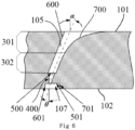
- Fig. 8 is an enlarged structural diagram of a first groove 105 in Fig. 7 .
- each first groove 105 includes a bottom 500 and two side surfaces 600 and 700.
- a plurality of discrete holes A 400 extending to the hollow cavity 15 are provided at the bottom of each first groove.
- the outer surface 101 of the turbine blade and the inner surface 102 of the turbine blade are substantially parallel to each other.
- the discrete holes A 400 are arranged substantially along a length direction of the first groove.
- the maximum diameter of the discrete holes A is d
- the depth of the first groove is H
- the minimum width of the first groove is D, wherein D ⁇ d, and H ⁇ 2d.
- the first portion 302 of the groove has an inclined cylinder shape, and in a vertical section as shown in Fig. 4 , two side surfaces of the first portion 302 of the groove are two straight line segments spaced apart from each other, the two straight line segments are parallel to each other, and an angle between each straight line segment of the first portion and the bottom of the first groove is 70°; one side surface of the second portion is also a straight line segment and is formed by extending from a corresponding side surface of the first portion, and the other side surface is an arc line segment and is formed by expanding in lateral direction from the other side surface of the first portion.
- an angle ⁇ between an axis of an opening end of each second portion in the depth direction and a normal of the surface 101 of the turbine blade is 30°.
- H 1 is slightly larger than H 2 .
- an angle ⁇ between a central axis of the discrete hole A and a normal of the inner surface 102 of the turbine blade is 15°, and an opening end of the hole is provided with a rounded transition to avoid the stress concentration phenomenon due to sharp angles.
- the flow path of the cooling gas at the wall of the turbine blade includes: the cooling gas inside the inner surface 102of the turbine blade enters the hollow cavity 15 via the discrete holes B, efficiently flows in the hollow cavity 15 and generates a positive pressure, and then enters the first groove via the discrete holes A; and the cooling gas from each discrete hole A may not only diffuse and mix in the length direction of the first groove, but also diffuse, mix, and superimpose on each other in the depth direction of the first groove.
- the gas may sufficiently spread in the first portion of the first groove to form a continuous and uniform gas with positive pressure, and then flows, via the second portion of the first groove, to an opening end at the outer surface of the turbine blade and flows out, to form a continuous and uniform gas film adhered on the outer surface of the turbine blade. Since the first groove has a relatively larger depth, the gas flowing out from the opening end of the first groove has a higher air pressure, and thus the continuous and uniform gas film formed on the outer surface of the turbine blade strongly attaches to the outer surface of the turbine blade.
- a method of manufacturing the above-mentioned turbine blade includes: first, separately preparing the turbine blade 100 in two parts, i.e., as shown in Fig. 2 , part I and part II, wherein part I and part II are combined at the combining line 106 to obtain a complete turbine blade 100; second, forming the first grooves 105 and the discrete holes A on an outer surface of part I, forming the discrete holes B on an inner surface of part I, forming the first grooves 105 and the discrete holes A on an outer surface of part II, and forming the discrete holes B on an inner surface of part II; and third, combining part I and part II at the combining line 106 to obtain a complete turbine blade 100.
Landscapes
- Engineering & Computer Science (AREA)
- Mechanical Engineering (AREA)
- General Engineering & Computer Science (AREA)
- Chemical & Material Sciences (AREA)
- Materials Engineering (AREA)
- Ceramic Engineering (AREA)
- Composite Materials (AREA)
- Physics & Mathematics (AREA)
- Fluid Mechanics (AREA)
- Turbine Rotor Nozzle Sealing (AREA)
Description
- The present invention relates to a turbine blade used in the technical fields of aero-engines, gas turbines and the like, particularly, to a turbine blade having a gas film cooling structure with an irregular groove.
- One of the key points of improving the working efficiency of aero-engines and gas turbines is to use high operating temperature. Blades are the core component of power equipment such as aero-engines and gas turbines. As an important part of thermal energy conversion, turbine blades are required to work with high temperature and high pressure alternating loads, i.e., not only be able to withstand an operating temperature higher than their own melting points, but also have sufficient strength to sustain mechanical loads such as a centrifugal force. For this reason, it is necessary for blades of modern aero-engines and gas turbines to be formed of high temperature resistant base materials and high temperature resistant thermal barrier coatings, and to generate temperature gradients by using a gas film cooling technology. Turbine blades are generally made of materials such as high temperature resistant alloys, single crystal metals, and ceramic base composite materials and so on. In the future, the operating temperature of a turbine of engine will be higher and higher, and advanced film cooling technologies are required as a solution for the temperature gap between the operating temperature and the sustainable temperature of the blade material.
- Generally, the turbine blade adopts a hollow structure, and a gas film cooling structure is provided to actively control the temperature of the blade, from which cooling gas is ejected to be isolated from high temperature air. The main purpose of a gas film cooling hole of gas film cooling structure is to form gas films attached to the surfaces of the blade, and it is desirable for the gas film to be formed uniformly on and attached closely to the surface of the blade closely. The gas film cooling structure used prior art was provided with straight circular holes in the early stage, which significantly increase the operating temperature as compared to a solid blade. However, the single-hole cooling protection area of the straight circular hole is relatively small, and the gas films seriously peel off when the blowing ratio is large, and thus, various three-dimensional irregular holes are widely used in advanced turbine blades, to significantly increase the single-hole cooling protection area and gas film adhesion as compared to regular holes regardless of blowing ratios. The gas film cooling holes are distributed discretely, the distribution and shape of the holes determine the uniformity of the gas film on the surface of the blades, and the uniformity of the film coverage becomes a key factor limiting the maximum cooling gradient of the turbine.
- It is necessary to optimize the design of gas film hole on the premise of ensuring strength of the turbine blade. Due to requirements of aerodynamics, the turbine blade has a twisted shape, the use of gas film cooling hole can only form strong gas film coverage on a part of the blade surface, and the isolation effect of the gas film is weak at some areas or even uncovered areas occur at the blade surface. The cooling effect can be improved by using a plurality of rows of dense gas film holes, but too many holes will increase the manufacturing cost and reduce reliability. In other words, too many gas film holes may reduce the structural strength of the blades. Therefore, a reliable temperature protection gradient of blades provided with discrete gas film holes is generally less than 300 degrees (Yahya, S M (2011), Turbines Compressors and Fans, New delhi: Tata McGraw-Hill Education, 2010. pp. 430-433).
- It is a long-term research hotspot about how to improve the gas film cooling structure to obtain turbine blades having a higher operating temperature. In order to improve the poor uniformity of the cooling effect of discrete gas film holes, for example, in patent documents
US20110097188A1 etc., gas film cooling holes are provided in shallow blind grooves which are perpendicular to the blade surface, to adjust the surface effect of the ejected airflow from the gas film holes, and blind groove structure with suitable sizes may bring benefits. In the above studies, the cooling holes play a main role in forming the initial gas film, and shallow grooves or grooves with certain depths on the blade surface are auxiliary structure for adjusting the airflow, and the length direction of the grooves are parallel to the centerline of the cooling hole. Although the uniformity of the gas film may be improved through the adjusted configuration according to these technologies, to form a continuous gas film on the blade surface cannot be solved completely. In addition, in the above solutions, the cooling gas is injected in the length direction of the grooves first, and then a gas film perpendicular to the groove is formed in accordance with the rotation effect of the turbine, which has limited effect on improving the uniformity of the gas film coverage of the blades.
DocumentUS 8,851,848 B1 discloses a turbine blade with showerhead film cooling slots.
DocumentUS 5,030,060 A1 discloses a method and apparatus for cooling high temperature ceramic turbine blade portions.
DocumentUS 7,563,073 B1 discloses a turbine blade film cooling slot. - The invention relates to a turbine blade according to claim 1. A turbine blade having a hollow structure and including a gas film cooling structure, wherein cooling gas ejected form an inner side of the turbine blade via the gas film cooling structure forms a continuous and uniform cooling gas film on an outer surface thereof, which is efficient in cooling and greatly improves the high temperature resistance of the turbine blade.
- In order to achieve the above technical objectives, the inventors of the present disclosure, after long-term research and exploration, provide a gas film cooling structure including discrete holes and grooves on the wall of the turbine blade, and the grooves are designed as irregular groove formed by two portions in a depth direction thereof, i.e., a first portion is a middle spreading groove for sufficiently spreading the cooling gas entering through the discrete holes to form a continuous and uniform gas with positive pressure, and a second portion is a lateral expended groove, which allows the gas with positive pressure flows out to outside of the outer surface of the turbine blade, form a continuous and uniform cooling gas film adhered on the outer surface of the turbine blade.
- That is, the technical solution of the present disclosure is as follows.
- A turbine blade having a gas film cooling structure with an irregular groove, wherein the turbine blade has a hollow structure, a plurality of first grooves which are recessed grooves are provided on an outer surface of the turbine blade, and the first groove includes a bottom and two side surfaces parallel to a length direction of the first groove, wherein a plurality of discrete holes A extending to an inner surface of the turbine blade are provided at the bottom of each first groove, the discrete holes A are arranged substantially along the length direction of the first groove, wherein a depth of each first groove is H, wherein the first groove includes at least two portions in a depth direction, a portion having a depth of H1 from the bottom of the first groove is a first portion, and a rest thereof is a second portion, i.e., a depth of the second portion is H2=H-H1, and wherein at least one side surface of the second portion is formed by expanding in lateral direction from a corresponding side surface of the first portion.
- In the turbine blade with the above structure, the cooling gas enters the first groove through the discrete holes A, and is sufficiently diffused and mixed in the first portion, forms a uniform gas with positive pressure, and then flows, via the second portion, to an opening end at the outer surface of the turbine blade and flows out, forming a uniform and continuous cooling gas film on the outer surface of the turbine blade.
- A method of manufacturing the turbine blade having the above-mentioned structure is not specially limited. For example, the turbine blade may be manufactured by 3D printing technology, integral processing technology, etc. The present disclosure also provides a method of manufacturing the above-mentioned turbine blade having a gas film cooling structure with an irregular groove comprising: first, separately preparing the turbine blade in at least two parts; second, forming the first grooves on an outer surface of each part, and forming the discrete holes A on an inner surface of each part; and third, combining the at least two parts to obtain the turbine blade having a gas film cooling structure with an irregular groove. Alternatively, the method comprises sequentially processing and forming the second portion, the first portion, and the discrete holes A of the first grooves on the outer surface of the turbine blade, thereby obtaining the turbine blade having a gas film cooling structure with an irregular groove.
- The manufacturing process is not specially limited, and may include mechanical processing, laser processing, electrochemical processing, and so on.
- In order to further improve the continuity, uniformity and adhesion of the cooling gas film, the present disclosure also proposes an optimized turbine blade structure.
- That is, a turbine blade having a gas film cooling structure with an irregular groove, wherein the turbine blade has a hollow structure, a plurality of first grooves which are recessed grooves are provided on an outer surface of the turbine blade, and an inner surface of the turbine blade includes a plurality of second grooves which are recessed grooves, wherein the first groove includes a bottom and two side surfaces parallel to a length direction of the first groove, wherein the second groove includes a bottom and two side surfaces parallel to a length direction of the second groove, wherein a plurality of discrete holes A extending to the bottom of the second groove are provided at the bottom of each first groove, and the discrete holes A are arranged substantially along the length direction of the first groove, wherein a depth of each first groove is H, wherein the first groove includes at least two portions in a depth direction, wherein a portion having a depth of H1 from the bottom of the first groove is a first portion, and a rest thereof is a second portion, i.e., a depth of the second portion is H2=H-H1, wherein at least one side surface of the second portion is formed by expanding in lateral direction from a corresponding side surface of the first portion.
- In the above optimized structure, the inner surface of the turbine blade is provided with the second grooves. By introducing the second grooves, the efficiency of the cooling airflow flowing to the discrete holes A is improved, generates a positive pressure, and reduces the processing depth of the gas ejecting hole.
- A height of the second groove is selectively determined to efficiently sputter the cooling gas and form a positive pressure.
- The method of manufacturing the turbine blade with the above structure is not specially limited. For example, the turbine blade may be manufactured by 3D printing technology, integral processing technology, etc. The present disclosure also provides a method of manufacturing the above-mentioned turbine blade having a gas film cooling structure with an irregular groove comprising: first, separately preparing the turbine blade in at least two parts; second, forming the first grooves on an outer surface of each part, and forming the second grooves and the discrete holes A on an inner surface of each part; and third, combining the at least two parts to obtain the turbine blade having a gas film cooling structure with an irregular groove.
- The manufacturing process is not limited, and may include mechanical processing, laser processing, electrochemical processing, and so on.
- In order to further improve the continuity, uniformity and adhesion of the cooling gas, the present disclosure also proposes another optimized turbine blade structure.
- A turbine blade having a gas film cooling structure with an irregular groove, wherein the turbine blade has a hollow structure, a hollow cavity is formed between an inner surface and an outer surface of the turbine blade, a plurality of discrete holes B extending to the hollow cavity are provided on the inner surface of the turbine blade, wherein a plurality of first grooves which are recessed grooves are provided on an outer surface of the turbine blade, and the first groove includes a bottom and two side surfaces parallel to a length direction of the first groove, wherein a plurality of discrete holes A extending to the hollow cavity are provided at the bottom of each first groove, and the discrete holes A are arranged substantially along the length direction of the first groove, wherein a depth of each first groove is H, wherein the groove includes at least two portions in a depth direction, a portion having a depth of H1 from the bottom of the first groove is a first portion, and a rest thereof is a second portion, i.e., a depth of the second portion is H2=H-H1, and wherein at least one side surface of the second portion is formed by expanding in lateral direction from a corresponding side surface of the first portion.
- In the optimized structure, the hollow cavity is formed between the inner surface and the outer surface of the turbine blade, the cooling gas first enters the hollow cavity via the discrete holes B for convective cooling, generates a positive pressure, and then enters the first groove via the discrete holes A.
- A height of the hollow cavity is selectively determined to efficiently sputter the cooling gas and form a positive pressure.
- Preferably, the discrete holes B and the discrete holes A are arranged in a staggered manner.
- The discrete holes B may be straight circular holes, diffusion holes, or complex three-dimensional irregular holes.
- Preferably, an opening end of the discrete holes B is provided with a chamfered transition or a rounded transition to avoid problems such as stress concentration phenomenon due to sharp angles, and unsmooth gas flow.
- The method of manufacturing the turbine blade with the above-mentioned structure is not specifically limited. For example, the turbine blade may be manufactured by 3D printing technology, integral processing technology, etc. The present disclosure also provides a method of manufacturing the above-mentioned turbine blade having a gas film cooling structure with an irregular groove comprising: first, separately preparing the turbine blade in at least two parts; second, forming the first grooves and the discrete holes A on an outer surface of each part, and forming the discrete holes B on an inner surface of each part; and third, combining the at least two parts to obtain the turbine blade having a gas film cooling structure with an irregular groove.
- The manufacturing process is not specifically limited, and may include mechanical processing, laser processing, electrochemical processing, and so on.
- Preferably, an angle between a central axis of a bottom of the first groove in the depth direction and a normal of the outer surface of the turbine blade is α, and 10°≤α≤90°, preferably 30°≤α≤80°, and more preferably 45°≤α≤70°.
- Preferably, in a vertical section of the first groove in a width direction of the first groove, two side surfaces of the first portion are two straight line segments spaced apart from each other, an angle between each straight line segment of the first portion and the bottom of the first groove is preferably 10° to 170°, more preferably 30° to 150°, and more preferably 60° to 120°. The two straight line segments may be parallel to each other, or may form a certain angle. Side surfaces of the second portion may be straight line segments or arc line segments, and preferably, at least one side surface of the second portion is an arc line segment. In addition, preferably, the connection portion where at least one side surface of the first portion and a corresponding side surface of the second portion are connected is a chamfered transition connection or an arc transition connection so that they are smoothly connected.
- The maximum diameter of each discrete hole A is d, and the minimum width of the first groove is D, wherein D≥ d and H≥ 2d, preferably, H≥ 3d, still more preferably, H≥ 4d.
- Further, H1>H2, preferably, H1:H2≥ 2:1, still more preferably, H1:H2≥ 3:1, and most preferably, H1:H2≥ 4:1.
- The inner surface and the outer surface of the turbine blade nay be parallel to each other, or may form a certain angle.
- The discrete holes A may be straight circular holes, diffusion holes, or complex three-dimensional irregular holes. Preferably, an angle between a central axis of the discrete hole A and the outer surface of the flame tube is θ. The angle α and angle θ may be different. Preferably, the angle θ is mainly to reduce a processing thickness of the holes. Generally, it is preferred that 0°≤θ≤60°, it is more preferred that 10°≤θ≤45°, and the angle α is configured to ensure a good gas film adhesion.
- Preferably, the opening end of the discrete hole A is provided with a chamfered transition, or a rounded transition to avoid problems such as stress concentration phenomenon due to sharp angles, and unsmooth gas flow.
- The arrangement of the first groove and the second groove on the outer surface of the turbine blade is not specifically limited. According to an actual shape of the outer surface of the turbine blade, the first groove and the second groove may be arranged in parallel or staggered, and is configured to form a gas film coverage on the entire outer surface of the turbine blade by a continuous gas film formed by the first groove.
- Compared with solutions in the prior art, in the present disclosure, the wall of the turbine blade is provided with the discrete holes A and the first grooves to form a gas film cooling structure, the first groove is an irregular groove including two portions in the depth direction of the groove, the first portion has a depth of H1, forms a middle expansion groove, the second portion has a depth of H2, forms a lateral expended groove. Such a structure has the following advantageous effects.
- (1) After the cooling gas enters the first groove through the discrete holes, since the first groove is an irregular groove including two portions, having a relatively larger depth, and the vertical section in the width direction of the first groove has a long and narrow shape. As shown in
Fig. 1 , diffused gas from each discrete hole may not only diffuse and mix in the length direction of the first groove, but also diffuse, mix, and superimpose on each other in the depth direction of the first groove. That is, the gas may sufficiently spread in the first portion of the first groove, forms a continuous and uniform gas with positive pressure, and then flows to the opening end via the second portion of the first groove. The shape of the opening end is optimized according to aerodynamic requirements of gas film adhesion, so that the gas flows out from a side close to the outer surface of the turbine blade, to form a continuous and uniform cooling gas film adhered on the outer surface of the turbine blade. Since the first groove has a relatively larger depth, the cooling gas flowing out from the opening end of the first groove has a higher air pressure, and thus the continuous and uniform cooling gas film formed on the outer surface of the turbine blade strongly attaches to the outer surface of the turbine blade. That is, in the present disclosure, the structure of the irregular groove is configured to form the continuous, uniform and strongly attached cooling gas film. The cooling gas enters the first groove through the discrete holes A, sufficiently diffuses and mixes in the first portion, forms a uniform gas with positive pressure, and then flows, via the second portion, to an opening end at the outer surface of the turbine blade and flows out to form a uniform and continuous gas film on the outer surface of the turbine blade. - (2) An aerodynamic simulation diagram of the turbine blade through which cooling gas passes according to the present disclosure. As shown in
Fig. 1 , it is confirmed that, in the present disclosure, the cooling gas may be injected into the first groove via the discrete holes A, expand and mix in the first groove and form a continuous and uniform gas with positive pressure, and form a gas film coverage on the entire outer surface of the turbine blade. - (3) It is confirmed by experiments that when the turbine blades in the combustion chamber of the present disclosure are in a high temperature gas environment, the cooling gas may form a gas film coverage on the entire outer surface of the turbine blade, and thus achieves a good cooling effect. When compared in the equivalent cooling efficiency = (gas temperature - temperature measured in the flame tube at a certain distance from the inner surface of the flame tube) / (gas temperature - temperature of the cooling gas), in the case that the blowing ratio of the cooling gas M = 1.5, in the turbine blade of the present disclosure, at a distance of larger than 10 mm from the outer surface of the turbine blade, the equivalent cooling efficiency is larger than 0.5, and when the blowing ratio of the cooling gas increases, the equivalent cooling efficiency may be increased to larger than 0.7.
- (4) The turbine blade of the present disclosure has a wide range of applications, including aero-engines, gas turbine aircrafts, flying cars, and power generation systems, etc.
-
-
Fig. 1 is an aerodynamic simulation diagram of the turbine blade of the present disclosure through which cooling gas passes. -
Fig. 2 is a schematic structure diagram of the turbine blade in embodiment 1 of the present disclosure. -
Fig. 3 is a schematic structure diagram illustrating a horizontal section ofFig. 2 . -
Fig. 4 is a schematic structure diagram of a first groove inFig. 3 . -
Fig. 5 is a schematic diagram of cooling gas flow in a first groove ofFig. 3 . -
Fig. 6 is a schematic structure diagram of the turbine blade in embodiment 2 of the present disclosure. -
Fig. 7 is a schematic structure diagram illustrating a horizontal section of the turbine blade in embodiment 3 of the present disclosure. -
Fig. 8 is a schematic structure diagram of a first groove inFig. 7 . - The present disclosure will be further described in detail below in conjunction with the embodiments. It should be indicated that the following embodiments are intended to facilitate the understanding of the present disclosure but not to limiting the scope of the present disclosure.
- Reference signs in
Figs. 2-8 : - 14 -
- discrete hole B;
- 15 -
- hollow cavity;
- 100 -
- turbine blade;
- 101 -
- outer surface of the turbine blade;
- 102 -
- inner surface of the turbine blade;
- 105 -
- first groove;
- 106 -
- combining line;
- 107 -
- second groove;
- 301 -
- second portion of the groove;
- 302 -
- first portion of the groove;
- 400 -
- discrete hole A;
- 500 -
- bottom of the first groove;
- 501 -
- bottom of the second groove;
- 600, 700 -
- two side surfaces of the first groove; and
- 601, 701 -
- two side surfaces of the second groove.
- In this embodiment, a
turbine blade 100 has a hollow structure, and a structural diagram of the turbine blade is shown inFig. 2, and Fig. 3 is a structural diagram illustrating a horizontal section ofFig. 2 . - A plurality of
first grooves 105 spaced apart from and parallel to each other are provided on anouter surface 101 of theturbine blade 100, and the first grooves may partially or entirely extend in a length direction of theouter surface 101 of theturbine blade 100. -
Fig. 4 is an enlarged structural diagram of afirst groove 105 inFig. 3 . - As illustrated in
Fig. 4 , each first groove includes a bottom 500 and two groove side surfaces 600 and 700. A plurality of discrete holes A 400 extending to aninner surface 102 of the turbine blade are provided at the bottom of each first groove. In the embodiment, theouter surface 101 of the turbine blade and theinner surface 102 of the turbine blade are substantially parallel to each other. As shown inFig. 1 , the discrete holes A 400 are arranged substantially in a length direction of thefirst groove 105. - The maximum diameter of the discrete holes A is d, the depth of the first groove is H, and the minimum width of the first groove is D, wherein D≥ d, and H≥ 2d.
- As shown in
Fig. 4 , the first groove includes two portions in the depth direction. A portion having a depth H1 from the bottom of the first groove is afirst portion 302, and the rest thereof is asecond portion 302. In other words, the depth of the second portion is H2=H-H1. - In the embodiment, the
first portion 302 of the groove has an inclined cylinder shape, and in a vertical section as shown inFig. 4 , two side surfaces of thefirst portion 302 of the groove are two straight line segments spaced apart from each other, the two straight line segments are parallel to each other, and an angle between each straight line segment of the first portion and the bottom of the first groove is 70°; one side surface of the second portion is also a straight line segment and is formed by extending from a corresponding side surface of the first portion, and the other side surface of the second portion is an arc line segment and is formed by expanding in lateral direction from the other side surface of the first portion. In the embodiment, an angle α between an axis of an opening end of each second portion in the depth direction and a normal of theouter surface 101 of the turbine blade is 30°. H1 is slightly larger than H2. - In the embodiment, an angle θ between a central axis of the discrete hole and a normal of the
inner surface 102 of the turbine blade is 15°, and an opening end of the hole is provided with a rounded transition to avoid the stress concentration phenomenon due to sharp angles. -
Fig. 5 is a schematic diagram of cooling gas flow in a first groove ofFig. 3 . After the cooling gas inside theinner surface 102 of the turbine blade enters the first groove through the discrete holes A, the gas from each discrete hole A may not only diffuse and mix in the length direction of the first groove, but also diffuse, mix, and superimpose on each other in the depth direction of the first groove. That is, the gas may sufficiently spread in the first portion of the first groove to form a continuous and uniform gas with positive pressure, and then flows, via the second portion of the first groove, to an opening end at the outer surface of the turbine blade and flows out, to form a continuous and uniform gas film adhered on theouter surface 101 of the turbine blade. Since the first groove has a relatively larger depth, the gas flowing out from the opening end of the first groove has a higher air pressure, and thus the continuous and uniform gas film formed on the outer surface of the turbine blade strongly attaches to the outer surface of the turbine blade. - In the embodiment, a method of manufacturing the above-mentioned turbine blade includes: first, separately preparing the
turbine blade 100 in two parts, i.e., as shown inFig. 2 , part I and part II, wherein part I and part II are combined at the combiningline 106 to obtain acomplete turbine blade 100; second, forming thefirst grooves 105 on an outer surface of part I, forming the discrete holes A on an inner surface of part I, forming thefirst grooves 105 on an outer surface of part II, and forming the discrete holes A on an inner surface of part II; and third, combining part I and part II at the combiningline 106 to obtain acomplete turbine blade 100. - In this embodiment, a
turbine blade 100 has a hollow structure, and a structural diagram of the turbine blade is shown inFig. 2, and Fig. 3 is a structural diagram illustrating a horizontal section ofFig. 2 . - A plurality of
first grooves 105 spaced apart from and parallel to each other are provided on anouter surface 101 of theturbine blade 100, the first grooves may partially or entirely extend in a length direction of theouter surface 101 of theturbine blade 100. A plurality ofsecond grooves 107 spaced apart from and parallel to each other are provided on aninner surface 102 of theturbine blade 100. -
Fig. 6 is an enlarged structural diagram of afirst groove 105 and asecond groove 107 inFig. 3 . - As illustrated in
Fig. 6 , each first groove includes a bottom 500 and twoside surfaces second groove 107 includes a bottom 501 and twoside surfaces first groove 105. - The maximum diameter of the discrete holes A is d, the depth of the first groove is H, and the minimum width of the first groove is D, wherein D≥ d, and H≥ 2d.
- The
first groove 105 includes two portions in the depth direction. As shown inFig. 6 , a portion having a depth of H1 from the bottom of the first groove is afirst portion 302, and the rest thereof is asecond portion 302. In other words, the depth of the second portion is H2=H-H1. - In the embodiment, the
first portion 302 of the groove has an inclined cylinder shape, and in a vertical section as shown inFig. 6 , two side surfaces of thefirst portion 302 of the groove are two straight line segments spaced apart from each other, the two straight line segments are parallel to each other, and an angle between each straight line segment of the first portion and the bottom of the first groove is 70°; one side surface of the second portion is also a straight line segment and is formed by extending from a corresponding side surface of the first portion, and the other side surface is an arc line segment and is formed by expanding in lateral direction from the other side surface of the first portion. In the embodiment, an angle α between an axis of an opening end of each second portion in the depth direction and a normal of thesurface 101 of the turbine blade is 30°. H1 is slightly larger than H2. - In the embodiment, an angle θ between a central axis of the discrete hole A and a normal of the
inner surface 102 of the turbine blade is 15°, and an opening end of the hole is provided with a rounded transition to avoid the stress concentration phenomenon due to sharp angles. - In the embodiment, the flow path of the cooling gas at the wall of the turbine blade includes: the cooling gas inside the
inner surface 102 of the turbine blade is transmitted to the second groove, and efficiently flows along the second groove and generates a positive pressure, and then enters the first groove via the discrete holes A; and the cooling gas from each discrete hole A may not only diffuse and mix in the length direction of the first groove, but also diffuse, mix, and superimpose on each other in the depth direction of the first groove. That is, the gas may sufficiently spread in the first portion of the first groove to form a continuous and uniform gas with positive pressure, and then flows, via the second portion of the first groove, to an opening end at the outer surface of the turbine blade and flows out, to form a continuous and uniform gas film adhered on the outer surface of the turbine blade. Since the first groove has a relatively larger depth, the gas flowing out from the opening end of the first groove has a higher air pressure, and thus the continuous and uniform gas film formed on the outer surface of the turbine blade strongly attaches to the outer surface of the turbine blade. - In the embodiment, a method of manufacturing the above-mentioned turbine blade includes: first, separately preparing the
turbine blade 100 in two parts, i.e., as shown inFig. 2 , part I and part II, wherein part I and part II are combined at the combiningline 106 to obtain acomplete turbine blade 100; second, forming thefirst grooves 105 on an outer surface of part I, forming thesecond grooves 107 and the discrete holes A on an inner surface of part I, forming thefirst grooves 105 on an outer surface of part II, and forming thesecond grooves 107 and the discrete holes A on an inner surface of part II; and third, combining part I and part II at the combiningline 106 to obtain acomplete turbine blade 100. - In this embodiment, a
turbine blade 100 has a hollow structure, and a structural diagram of the turbine blade is shown inFig. 2 , andFig. 7 is a structural diagram illustrating a horizontal section ofFig. 2 . - As shown in
Fig. 7 , ahollow cavity 15 is formed between aninner surface 102 and anouter surface 101 of theturbine blade 100. A plurality ofdiscrete holes B 14 extending to thehollow cavity 15 are provided on theinner surface 102 of the turbine blade. - A plurality of
first grooves 105 spaced apart from and parallel to each other are provided on anouter surface 101 of theturbine blade 100, the first grooves may have a length partially or entirely extending in a length direction of theouter surface 101 of theturbine blade 100. -
Fig. 8 is an enlarged structural diagram of afirst groove 105 inFig. 7 . - As illustrated in
Fig. 8 , eachfirst groove 105 includes a bottom 500 and twoside surfaces hollow cavity 15 are provided at the bottom of each first groove. - In the embodiment, the
outer surface 101 of the turbine blade and theinner surface 102 of the turbine blade are substantially parallel to each other. As shown inFig. 1 , the discrete holes A 400 are arranged substantially along a length direction of the first groove. - The maximum diameter of the discrete holes A is d, the depth of the first groove is H, and the minimum width of the first groove is D, wherein D≥ d, and H≥ 2d.
- In the embodiment, the first groove includes two portions in the depth direction. As shown in
Fig. 4 , a portion having a depth of H1 from the bottom of the first groove is afirst portion 302, and the rest thereof is asecond portion 302. In other words, the depth of the second portion is H2=H-H1. - In the embodiment, the
first portion 302 of the groove has an inclined cylinder shape, and in a vertical section as shown inFig. 4 , two side surfaces of thefirst portion 302 of the groove are two straight line segments spaced apart from each other, the two straight line segments are parallel to each other, and an angle between each straight line segment of the first portion and the bottom of the first groove is 70°; one side surface of the second portion is also a straight line segment and is formed by extending from a corresponding side surface of the first portion, and the other side surface is an arc line segment and is formed by expanding in lateral direction from the other side surface of the first portion. In the embodiment, an angle α between an axis of an opening end of each second portion in the depth direction and a normal of thesurface 101 of the turbine blade is 30°. H1 is slightly larger than H2. - In the embodiment, an angle θ between a central axis of the discrete hole A and a normal of the
inner surface 102 of the turbine blade is 15°, and an opening end of the hole is provided with a rounded transition to avoid the stress concentration phenomenon due to sharp angles. - In the embodiment, the flow path of the cooling gas at the wall of the turbine blade includes: the cooling gas inside the inner surface 102of the turbine blade enters the
hollow cavity 15 via the discrete holes B, efficiently flows in thehollow cavity 15 and generates a positive pressure, and then enters the first groove via the discrete holes A; and the cooling gas from each discrete hole A may not only diffuse and mix in the length direction of the first groove, but also diffuse, mix, and superimpose on each other in the depth direction of the first groove. That is, the gas may sufficiently spread in the first portion of the first groove to form a continuous and uniform gas with positive pressure, and then flows, via the second portion of the first groove, to an opening end at the outer surface of the turbine blade and flows out, to form a continuous and uniform gas film adhered on the outer surface of the turbine blade. Since the first groove has a relatively larger depth, the gas flowing out from the opening end of the first groove has a higher air pressure, and thus the continuous and uniform gas film formed on the outer surface of the turbine blade strongly attaches to the outer surface of the turbine blade. - In the embodiment, a method of manufacturing the above-mentioned turbine blade includes: first, separately preparing the
turbine blade 100 in two parts, i.e., as shown inFig. 2 , part I and part II, wherein part I and part II are combined at the combiningline 106 to obtain acomplete turbine blade 100; second, forming thefirst grooves 105 and the discrete holes A on an outer surface of part I, forming the discrete holes B on an inner surface of part I, forming thefirst grooves 105 and the discrete holes A on an outer surface of part II, and forming the discrete holes B on an inner surface of part II; and third, combining part I and part II at the combiningline 106 to obtain acomplete turbine blade 100. - The above-mentioned embodiments are detailed descriptions of the technical solution of the present invention. Any modifications, supplements, or substitutions within the scope of the appended claims shall be included under the scope of protection.
Claims (13)
- A turbine blade (100) having a gas film cooling structure, wherein the turbine blade (100) has a hollow structure, and a plurality of first grooves (105) which are irregular grooves are provided on an outer surface (101) of a wall of the turbine blade (100),wherein each first groove (105) comprises a bottom (500) and two side surfaces (600, 700) parallel to a length direction of the first groove (105),whereina plurality of discrete holes A (400) extending to an inner surface (102) of the wall of the turbine blade (100) are provided at the bottom (500) of each first groove (105), and the discrete holes A (400) are arranged substantially along the length direction of the first groove (105),wherein a depth of each first groove (105) is H,wherein each first groove (105) includes at least two portions in a depth direction, a portion having a depth of H1 from the bottom (500) of the first groove (105) is a first portion (301), and a rest thereof is a second portion (302), i.e., a depth of the second portion (302) is H2=H-H1,characterized in thatat least one side surface of the second portion (302) is formed by expanding in lateral direction from a corresponding side surface of the first portion (301),wherein the maximum diameter of each discrete hole A (400) is d, the depth of each first groove (105) is H, and the minimum width of each first groove (105) is D, andwherein D≥ d, H≥ 2d, and H1>H2.
- The turbine blade (100) having a gas film cooling structure according to any of previous claims, wherein an angle between an axis of an opening end of each first groove (105) in the depth direction and a normal of the outer surface (101) of the turbine blade (100) is α, and 10°≤α≤90°, preferably 30°≤α≤80°, and more preferably 45°≤α≤70°.
- The turbine blade (100) having a gas film cooling structure according to any of previous claims, wherein in a vertical section of the first groove (105) in a width direction of the first groove (105), two side surfaces of the first portion (301) are two straight line segments spaced apart from each other.
- The turbine blade (100) having a gas film cooling structure according to claim 3, wherein an angle between each straight line segment of the first portion (301) and the bottom (500) of the first groove (105) is 10° to 170°, preferably 30° to 150°, and more preferably 60° to 120°.
- The turbine blade (100) having a gas film cooling structure according to claim 3, wherein at least one side surface of the second portion (302) is an arc line segment.
- The turbine blade (100) having a gas film cooling structure according to any of previous claims, wherein a connection portion where at least one side surface of the first portion (301) and a corresponding side surface of the second portion (302) are connected is a chamfered transition connection or an arc transition connection.
- The turbine blade (100) having a gas film cooling structure according to any of previous claims, wherein H≥ 3d.
- The turbine blade (100) having a gas film cooling structure according to claim 7, wherein H≥ 4d.
- The turbine blade (100) having a gas film cooling structure according to any of previous claims, wherein the discrete holes A (400) are straight circular holes, diffusion holes, or complex irregular holes,wherein preferably, an angle between a central axis of each discrete hole A (400) and a normal of surface of the turbine blade (100) is θ, 0°≤θ≤60°, and preferably, 10°≤θ≤45°, andwherein preferably, an opening end of each discrete hole A (400) is provided with a chamfered transition, or a rounded transition.
- The turbine blade (100) having a gas film cooling structure according to any of previous claims, wherein a gas film formed by each first groove (105) forms a continuous coverage on an entire surface of the turbine blade (100).
- 4&- The turbine blade (100) having a gas film cooling structure according to any of previous claims, wherein H1:H2≥ 2:1.
- The turbine blade (100) having a gas film cooling structure according to claim 11, wherein H1:H2≥ 3:1.
- The turbine blade (100) having a gas film cooling structure according to claim 12, wherein H1:H2≥ 4:1.
Applications Claiming Priority (2)
| Application Number | Priority Date | Filing Date | Title |
|---|---|---|---|
| CN201810911051.8A CN108843404B (en) | 2018-08-10 | 2018-08-10 | A kind of turbine blade with compound special-shaped groove film cooling structure and its preparation method |
| PCT/CN2018/125109 WO2020029531A1 (en) | 2018-08-10 | 2018-12-28 | Turbine blade having composite specially-shaped slotted gas film cooling structure and manufacturing method thereof |
Publications (3)
| Publication Number | Publication Date |
|---|---|
| EP3835549A1 EP3835549A1 (en) | 2021-06-16 |
| EP3835549A4 EP3835549A4 (en) | 2022-06-22 |
| EP3835549B1 true EP3835549B1 (en) | 2024-03-20 |
Family
ID=64195546
Family Applications (1)
| Application Number | Title | Priority Date | Filing Date |
|---|---|---|---|
| EP18929083.6A Active EP3835549B1 (en) | 2018-08-10 | 2018-12-28 | Turbine blade having composite specially-shaped slotted gas film cooling structure |
Country Status (5)
| Country | Link |
|---|---|
| US (1) | US11352888B2 (en) |
| EP (1) | EP3835549B1 (en) |
| JP (1) | JP7268135B2 (en) |
| CN (1) | CN108843404B (en) |
| WO (1) | WO2020029531A1 (en) |
Families Citing this family (5)
| Publication number | Priority date | Publication date | Assignee | Title |
|---|---|---|---|---|
| CN108843404B (en) | 2018-08-10 | 2023-02-24 | 中国科学院宁波材料技术与工程研究所 | A kind of turbine blade with compound special-shaped groove film cooling structure and its preparation method |
| CN112282859A (en) * | 2020-11-13 | 2021-01-29 | 中国民航大学 | A turbine blade with a fractal structure in the cross section of the inner cooling channel |
| US12006837B2 (en) * | 2022-01-28 | 2024-06-11 | Rtx Corporation | Ceramic matrix composite article and method of making the same |
| CN116140814B (en) * | 2023-02-24 | 2024-01-30 | 中国科学院西安光学精密机械研究所 | A trajectory planning method for the non-etching section of laser processing of blade air film holes |
| US12435634B2 (en) | 2023-11-21 | 2025-10-07 | Rolls-Royce North American Technologies Inc. | Notched turbine airfoils for weight reduction in gas turbine engines |
Family Cites Families (33)
| Publication number | Priority date | Publication date | Assignee | Title |
|---|---|---|---|---|
| US4738588A (en) * | 1985-12-23 | 1988-04-19 | Field Robert E | Film cooling passages with step diffuser |
| US4684323A (en) * | 1985-12-23 | 1987-08-04 | United Technologies Corporation | Film cooling passages with curved corners |
| US5030060A (en) * | 1988-10-20 | 1991-07-09 | The United States Of America As Represented By The Secretary Of The Air Force | Method and apparatus for cooling high temperature ceramic turbine blade portions |
| US5419681A (en) * | 1993-01-25 | 1995-05-30 | General Electric Company | Film cooled wall |
| US5458461A (en) * | 1994-12-12 | 1995-10-17 | General Electric Company | Film cooled slotted wall |
| US6547524B2 (en) * | 2001-05-21 | 2003-04-15 | United Technologies Corporation | Film cooled article with improved temperature tolerance |
| US20050220618A1 (en) * | 2004-03-31 | 2005-10-06 | General Electric Company | Counter-bored film-cooling holes and related method |
| US7246999B2 (en) * | 2004-10-06 | 2007-07-24 | General Electric Company | Stepped outlet turbine airfoil |
| US7374401B2 (en) * | 2005-03-01 | 2008-05-20 | General Electric Company | Bell-shaped fan cooling holes for turbine airfoil |
| US7563073B1 (en) * | 2006-10-10 | 2009-07-21 | Florida Turbine Technologies, Inc. | Turbine blade with film cooling slot |
| US7887294B1 (en) * | 2006-10-13 | 2011-02-15 | Florida Turbine Technologies, Inc. | Turbine airfoil with continuous curved diffusion film holes |
| CN100485166C (en) * | 2007-04-30 | 2009-05-06 | 西安交通大学 | Grooving gaseous film cooling hole |
| US8066484B1 (en) * | 2007-11-19 | 2011-11-29 | Florida Turbine Technologies, Inc. | Film cooling hole for a turbine airfoil |
| US8057179B1 (en) * | 2008-10-16 | 2011-11-15 | Florida Turbine Technologies, Inc. | Film cooling hole for turbine airfoil |
| US7997868B1 (en) * | 2008-11-18 | 2011-08-16 | Florida Turbine Technologies, Inc. | Film cooling hole for turbine airfoil |
| US20110097188A1 (en) * | 2009-10-23 | 2011-04-28 | General Electric Company | Structure and method for improving film cooling using shallow trench with holes oriented along length of trench |
| US8672613B2 (en) * | 2010-08-31 | 2014-03-18 | General Electric Company | Components with conformal curved film holes and methods of manufacture |
| CN102022139A (en) * | 2010-12-10 | 2011-04-20 | 南京航空航天大学 | Internal cooling device and method thereof for ground gas turbine blade |
| US8851848B1 (en) * | 2012-02-20 | 2014-10-07 | Florida Turbine Technologies, Inc. | Turbine blade with showerhead film cooling slots |
| US9228437B1 (en) * | 2012-03-22 | 2016-01-05 | Florida Turbine Technologies, Inc. | Turbine airfoil with pressure side trailing edge cooling slots |
| US20130315710A1 (en) * | 2012-05-22 | 2013-11-28 | Honeywell International Inc. | Gas turbine engine components with cooling hole trenches |
| EP2941543B1 (en) * | 2013-03-13 | 2017-03-22 | Rolls-Royce Corporation | Trenched cooling hole arrangement for a ceramic matrix composite vane |
| BR112015031098A2 (en) | 2013-07-03 | 2017-07-25 | Gen Electric | airfoil |
| CN103696811A (en) | 2013-12-19 | 2014-04-02 | 中国科学院工程热物理研究所 | Turbine blade round hole air film cooling structure with strip slit opening |
| CN203867627U (en) * | 2014-03-27 | 2014-10-08 | 中航商用航空发动机有限责任公司 | Air film cooling component for gas turbine |
| CN203796330U (en) * | 2014-04-03 | 2014-08-27 | 中国科学院工程热物理研究所 | Cross-arrangement type double-laminate cooling structure |
| US10233775B2 (en) * | 2014-10-31 | 2019-03-19 | General Electric Company | Engine component for a gas turbine engine |
| US10378444B2 (en) * | 2015-08-19 | 2019-08-13 | General Electric Company | Engine component for a gas turbine engine |
| CN205558979U (en) | 2016-04-22 | 2016-09-07 | 中航商用航空发动机有限责任公司 | Treat cooling wall body structure, turbine blade and aeroengine |
| CN106593543B (en) | 2016-11-28 | 2018-04-17 | 西北工业大学 | A kind of arch form groove gaseous film control structure for turbo blade |
| CN108223019A (en) * | 2017-12-20 | 2018-06-29 | 中国科学院宁波材料技术与工程研究所 | A kind of hollow blade and its manufacturing method and application |
| CN108843404B (en) | 2018-08-10 | 2023-02-24 | 中国科学院宁波材料技术与工程研究所 | A kind of turbine blade with compound special-shaped groove film cooling structure and its preparation method |
| CN208845235U (en) * | 2018-08-10 | 2019-05-10 | 中国科学院宁波材料技术与工程研究所 | A kind of turbo blade with compound special-shaped groove gaseous film control structure |
-
2018
- 2018-08-10 CN CN201810911051.8A patent/CN108843404B/en active Active
- 2018-12-28 EP EP18929083.6A patent/EP3835549B1/en active Active
- 2018-12-28 JP JP2021507967A patent/JP7268135B2/en active Active
- 2018-12-28 US US17/267,695 patent/US11352888B2/en active Active
- 2018-12-28 WO PCT/CN2018/125109 patent/WO2020029531A1/en not_active Ceased
Also Published As
| Publication number | Publication date |
|---|---|
| EP3835549A1 (en) | 2021-06-16 |
| JP2021535312A (en) | 2021-12-16 |
| US20210310361A1 (en) | 2021-10-07 |
| CN108843404B (en) | 2023-02-24 |
| CN108843404A (en) | 2018-11-20 |
| WO2020029531A1 (en) | 2020-02-13 |
| US11352888B2 (en) | 2022-06-07 |
| JP7268135B2 (en) | 2023-05-02 |
| EP3835549A4 (en) | 2022-06-22 |
Similar Documents
| Publication | Publication Date | Title |
|---|---|---|
| US11352888B2 (en) | Turbine blade having gas film cooling structure with a composite irregular groove and a method of manufacturing the same | |
| US10436040B2 (en) | Airfoil with dual-wall cooling for a gas turbine engine | |
| US10487666B2 (en) | Cooling hole with enhanced flow attachment | |
| Ekkad et al. | A review of hole geometry and coolant density effect on film cooling | |
| US7497660B2 (en) | Multi-metered film cooled blade tip | |
| US8753083B2 (en) | Curved cooling passages for a turbine component | |
| US8523527B2 (en) | Apparatus for cooling a platform of a turbine component | |
| EP1898051B1 (en) | Gas turbine airfoil with leading edge cooling | |
| CN108731030B (en) | A combustion chamber with a composite special-shaped groove film cooling structure | |
| US10668528B2 (en) | Method for producing a rotor blade | |
| EP2527597A2 (en) | Turbine blade with curved film cooling passages | |
| US4835958A (en) | Process for directing a combustion gas stream onto rotatable blades of a gas turbine | |
| CN113374536B (en) | Gas turbine guide vane | |
| JP2014219002A (en) | Substrate with shaped cooling holes and methods of manufacture thereof | |
| EP2899370A1 (en) | Turbine blade having swirling cooling channel and cooling method thereof | |
| EP3943712A1 (en) | Airfoil cooling holes | |
| CN105339593B (en) | The groove cooling of thumbpiece structure | |
| US4543781A (en) | Annular combustor for gas turbine | |
| CN208845235U (en) | A kind of turbo blade with compound special-shaped groove gaseous film control structure | |
| US9441488B1 (en) | Film cooling holes for gas turbine airfoils | |
| CN209013233U (en) | A kind of combustion chamber with compound special-shaped groove gaseous film control structure | |
| CN114046180B (en) | Combined hole air film cooling structure utilizing rotational flow | |
| CN108590777A (en) | A kind of recurring structure of the continuous air film of matrix surface | |
| CN108843403B (en) | Method for generating continuous gas film on surface of substrate | |
| RU2787678C2 (en) | Turbine blade with structure for gas-film cooling with composite groove of irregular shape and its manufacturing method |
Legal Events
| Date | Code | Title | Description |
|---|---|---|---|
| STAA | Information on the status of an ep patent application or granted ep patent |
Free format text: STATUS: THE INTERNATIONAL PUBLICATION HAS BEEN MADE |
|
| PUAI | Public reference made under article 153(3) epc to a published international application that has entered the european phase |
Free format text: ORIGINAL CODE: 0009012 |
|
| STAA | Information on the status of an ep patent application or granted ep patent |
Free format text: STATUS: REQUEST FOR EXAMINATION WAS MADE |
|
| 17P | Request for examination filed |
Effective date: 20210310 |
|
| AK | Designated contracting states |
Kind code of ref document: A1 Designated state(s): AL AT BE BG CH CY CZ DE DK EE ES FI FR GB GR HR HU IE IS IT LI LT LU LV MC MK MT NL NO PL PT RO RS SE SI SK SM TR |
|
| DAV | Request for validation of the european patent (deleted) | ||
| DAX | Request for extension of the european patent (deleted) | ||
| A4 | Supplementary search report drawn up and despatched |
Effective date: 20220524 |
|
| RIC1 | Information provided on ipc code assigned before grant |
Ipc: F01D 5/28 20060101ALI20220519BHEP Ipc: F01D 5/18 20060101AFI20220519BHEP |
|
| GRAP | Despatch of communication of intention to grant a patent |
Free format text: ORIGINAL CODE: EPIDOSNIGR1 |
|
| STAA | Information on the status of an ep patent application or granted ep patent |
Free format text: STATUS: GRANT OF PATENT IS INTENDED |
|
| INTG | Intention to grant announced |
Effective date: 20230925 |
|
| RAP3 | Party data changed (applicant data changed or rights of an application transferred) |
Owner name: NINGBO III LASERS TECHNOLOGY CO., LTD Owner name: NINGBO INSTITUTE OF MATERIAL TECHNOLOGY AND ENGINEERING CHINESE ACADEMY OF SCIENCES |
|
| GRAS | Grant fee paid |
Free format text: ORIGINAL CODE: EPIDOSNIGR3 |
|
| GRAA | (expected) grant |
Free format text: ORIGINAL CODE: 0009210 |
|
| STAA | Information on the status of an ep patent application or granted ep patent |
Free format text: STATUS: THE PATENT HAS BEEN GRANTED |
|
| RAP3 | Party data changed (applicant data changed or rights of an application transferred) |
Owner name: NINGBO III LASERS TECHNOLOGY CO., LTD Owner name: NINGBO INSTITUTE OF MATERIAL TECHNOLOGY AND ENGINEERING CHINESE ACADEMY OF SCIENCES |
|
| AK | Designated contracting states |
Kind code of ref document: B1 Designated state(s): AL AT BE BG CH CY CZ DE DK EE ES FI FR GB GR HR HU IE IS IT LI LT LU LV MC MK MT NL NO PL PT RO RS SE SI SK SM TR |
|
| RAP3 | Party data changed (applicant data changed or rights of an application transferred) |
Owner name: NINGBO III LASERS TECHNOLOGY CO., LTD Owner name: NINGBO INSTITUTE OF MATERIALS TECHNOLOGY AND ENGINEERING, CHINESE ACADEMY OF SCIENCES |
|
| REG | Reference to a national code |
Ref country code: GB Ref legal event code: FG4D |
|
| RAP4 | Party data changed (patent owner data changed or rights of a patent transferred) |
Owner name: NINGBO INSTITUTE OF MATERIALS TECHNOLOGY AND ENGINEERING, CHINESE ACADEMY OF SCIENCES Owner name: NINGBO III LASERS TECHNOLOGY CO., LTD |
|
| REG | Reference to a national code |
Ref country code: CH Ref legal event code: EP |
|
| REG | Reference to a national code |
Ref country code: DE Ref legal event code: R096 Ref document number: 602018067037 Country of ref document: DE |
|
| REG | Reference to a national code |
Ref country code: IE Ref legal event code: FG4D |
|
| PG25 | Lapsed in a contracting state [announced via postgrant information from national office to epo] |
Ref country code: LT Free format text: LAPSE BECAUSE OF FAILURE TO SUBMIT A TRANSLATION OF THE DESCRIPTION OR TO PAY THE FEE WITHIN THE PRESCRIBED TIME-LIMIT Effective date: 20240320 |
|
| REG | Reference to a national code |
Ref country code: LT Ref legal event code: MG9D |
|
| PG25 | Lapsed in a contracting state [announced via postgrant information from national office to epo] |
Ref country code: GR Free format text: LAPSE BECAUSE OF FAILURE TO SUBMIT A TRANSLATION OF THE DESCRIPTION OR TO PAY THE FEE WITHIN THE PRESCRIBED TIME-LIMIT Effective date: 20240621 |
|
| PG25 | Lapsed in a contracting state [announced via postgrant information from national office to epo] |
Ref country code: RS Free format text: LAPSE BECAUSE OF FAILURE TO SUBMIT A TRANSLATION OF THE DESCRIPTION OR TO PAY THE FEE WITHIN THE PRESCRIBED TIME-LIMIT Effective date: 20240620 Ref country code: HR Free format text: LAPSE BECAUSE OF FAILURE TO SUBMIT A TRANSLATION OF THE DESCRIPTION OR TO PAY THE FEE WITHIN THE PRESCRIBED TIME-LIMIT Effective date: 20240320 |
|
| REG | Reference to a national code |
Ref country code: NL Ref legal event code: MP Effective date: 20240320 |
|
| PG25 | Lapsed in a contracting state [announced via postgrant information from national office to epo] |
Ref country code: RS Free format text: LAPSE BECAUSE OF FAILURE TO SUBMIT A TRANSLATION OF THE DESCRIPTION OR TO PAY THE FEE WITHIN THE PRESCRIBED TIME-LIMIT Effective date: 20240620 Ref country code: NO Free format text: LAPSE BECAUSE OF FAILURE TO SUBMIT A TRANSLATION OF THE DESCRIPTION OR TO PAY THE FEE WITHIN THE PRESCRIBED TIME-LIMIT Effective date: 20240620 Ref country code: LT Free format text: LAPSE BECAUSE OF FAILURE TO SUBMIT A TRANSLATION OF THE DESCRIPTION OR TO PAY THE FEE WITHIN THE PRESCRIBED TIME-LIMIT Effective date: 20240320 Ref country code: HR Free format text: LAPSE BECAUSE OF FAILURE TO SUBMIT A TRANSLATION OF THE DESCRIPTION OR TO PAY THE FEE WITHIN THE PRESCRIBED TIME-LIMIT Effective date: 20240320 Ref country code: GR Free format text: LAPSE BECAUSE OF FAILURE TO SUBMIT A TRANSLATION OF THE DESCRIPTION OR TO PAY THE FEE WITHIN THE PRESCRIBED TIME-LIMIT Effective date: 20240621 Ref country code: FI Free format text: LAPSE BECAUSE OF FAILURE TO SUBMIT A TRANSLATION OF THE DESCRIPTION OR TO PAY THE FEE WITHIN THE PRESCRIBED TIME-LIMIT Effective date: 20240320 Ref country code: BG Free format text: LAPSE BECAUSE OF FAILURE TO SUBMIT A TRANSLATION OF THE DESCRIPTION OR TO PAY THE FEE WITHIN THE PRESCRIBED TIME-LIMIT Effective date: 20240320 |
|
| REG | Reference to a national code |
Ref country code: AT Ref legal event code: MK05 Ref document number: 1667989 Country of ref document: AT Kind code of ref document: T Effective date: 20240320 |
|
| PG25 | Lapsed in a contracting state [announced via postgrant information from national office to epo] |
Ref country code: SE Free format text: LAPSE BECAUSE OF FAILURE TO SUBMIT A TRANSLATION OF THE DESCRIPTION OR TO PAY THE FEE WITHIN THE PRESCRIBED TIME-LIMIT Effective date: 20240320 Ref country code: LV Free format text: LAPSE BECAUSE OF FAILURE TO SUBMIT A TRANSLATION OF THE DESCRIPTION OR TO PAY THE FEE WITHIN THE PRESCRIBED TIME-LIMIT Effective date: 20240320 |
|
| PG25 | Lapsed in a contracting state [announced via postgrant information from national office to epo] |
Ref country code: NL Free format text: LAPSE BECAUSE OF FAILURE TO SUBMIT A TRANSLATION OF THE DESCRIPTION OR TO PAY THE FEE WITHIN THE PRESCRIBED TIME-LIMIT Effective date: 20240320 |
|
| PG25 | Lapsed in a contracting state [announced via postgrant information from national office to epo] |
Ref country code: NL Free format text: LAPSE BECAUSE OF FAILURE TO SUBMIT A TRANSLATION OF THE DESCRIPTION OR TO PAY THE FEE WITHIN THE PRESCRIBED TIME-LIMIT Effective date: 20240320 |
|
| PG25 | Lapsed in a contracting state [announced via postgrant information from national office to epo] |
Ref country code: IS Free format text: LAPSE BECAUSE OF FAILURE TO SUBMIT A TRANSLATION OF THE DESCRIPTION OR TO PAY THE FEE WITHIN THE PRESCRIBED TIME-LIMIT Effective date: 20240720 |
|
| PG25 | Lapsed in a contracting state [announced via postgrant information from national office to epo] |
Ref country code: PT Free format text: LAPSE BECAUSE OF FAILURE TO SUBMIT A TRANSLATION OF THE DESCRIPTION OR TO PAY THE FEE WITHIN THE PRESCRIBED TIME-LIMIT Effective date: 20240722 Ref country code: SM Free format text: LAPSE BECAUSE OF FAILURE TO SUBMIT A TRANSLATION OF THE DESCRIPTION OR TO PAY THE FEE WITHIN THE PRESCRIBED TIME-LIMIT Effective date: 20240320 |
|
| PG25 | Lapsed in a contracting state [announced via postgrant information from national office to epo] |
Ref country code: ES Free format text: LAPSE BECAUSE OF FAILURE TO SUBMIT A TRANSLATION OF THE DESCRIPTION OR TO PAY THE FEE WITHIN THE PRESCRIBED TIME-LIMIT Effective date: 20240320 |
|
| PG25 | Lapsed in a contracting state [announced via postgrant information from national office to epo] |
Ref country code: EE Free format text: LAPSE BECAUSE OF FAILURE TO SUBMIT A TRANSLATION OF THE DESCRIPTION OR TO PAY THE FEE WITHIN THE PRESCRIBED TIME-LIMIT Effective date: 20240320 Ref country code: CZ Free format text: LAPSE BECAUSE OF FAILURE TO SUBMIT A TRANSLATION OF THE DESCRIPTION OR TO PAY THE FEE WITHIN THE PRESCRIBED TIME-LIMIT Effective date: 20240320 |
|
| PG25 | Lapsed in a contracting state [announced via postgrant information from national office to epo] |
Ref country code: AT Free format text: LAPSE BECAUSE OF FAILURE TO SUBMIT A TRANSLATION OF THE DESCRIPTION OR TO PAY THE FEE WITHIN THE PRESCRIBED TIME-LIMIT Effective date: 20240320 |
|
| PG25 | Lapsed in a contracting state [announced via postgrant information from national office to epo] |
Ref country code: PL Free format text: LAPSE BECAUSE OF FAILURE TO SUBMIT A TRANSLATION OF THE DESCRIPTION OR TO PAY THE FEE WITHIN THE PRESCRIBED TIME-LIMIT Effective date: 20240320 |
|
| PG25 | Lapsed in a contracting state [announced via postgrant information from national office to epo] |
Ref country code: SK Free format text: LAPSE BECAUSE OF FAILURE TO SUBMIT A TRANSLATION OF THE DESCRIPTION OR TO PAY THE FEE WITHIN THE PRESCRIBED TIME-LIMIT Effective date: 20240320 |
|
| PG25 | Lapsed in a contracting state [announced via postgrant information from national office to epo] |
Ref country code: SM Free format text: LAPSE BECAUSE OF FAILURE TO SUBMIT A TRANSLATION OF THE DESCRIPTION OR TO PAY THE FEE WITHIN THE PRESCRIBED TIME-LIMIT Effective date: 20240320 Ref country code: SK Free format text: LAPSE BECAUSE OF FAILURE TO SUBMIT A TRANSLATION OF THE DESCRIPTION OR TO PAY THE FEE WITHIN THE PRESCRIBED TIME-LIMIT Effective date: 20240320 Ref country code: RO Free format text: LAPSE BECAUSE OF FAILURE TO SUBMIT A TRANSLATION OF THE DESCRIPTION OR TO PAY THE FEE WITHIN THE PRESCRIBED TIME-LIMIT Effective date: 20240320 Ref country code: PT Free format text: LAPSE BECAUSE OF FAILURE TO SUBMIT A TRANSLATION OF THE DESCRIPTION OR TO PAY THE FEE WITHIN THE PRESCRIBED TIME-LIMIT Effective date: 20240722 Ref country code: PL Free format text: LAPSE BECAUSE OF FAILURE TO SUBMIT A TRANSLATION OF THE DESCRIPTION OR TO PAY THE FEE WITHIN THE PRESCRIBED TIME-LIMIT Effective date: 20240320 Ref country code: IS Free format text: LAPSE BECAUSE OF FAILURE TO SUBMIT A TRANSLATION OF THE DESCRIPTION OR TO PAY THE FEE WITHIN THE PRESCRIBED TIME-LIMIT Effective date: 20240720 Ref country code: ES Free format text: LAPSE BECAUSE OF FAILURE TO SUBMIT A TRANSLATION OF THE DESCRIPTION OR TO PAY THE FEE WITHIN THE PRESCRIBED TIME-LIMIT Effective date: 20240320 Ref country code: EE Free format text: LAPSE BECAUSE OF FAILURE TO SUBMIT A TRANSLATION OF THE DESCRIPTION OR TO PAY THE FEE WITHIN THE PRESCRIBED TIME-LIMIT Effective date: 20240320 Ref country code: CZ Free format text: LAPSE BECAUSE OF FAILURE TO SUBMIT A TRANSLATION OF THE DESCRIPTION OR TO PAY THE FEE WITHIN THE PRESCRIBED TIME-LIMIT Effective date: 20240320 Ref country code: AT Free format text: LAPSE BECAUSE OF FAILURE TO SUBMIT A TRANSLATION OF THE DESCRIPTION OR TO PAY THE FEE WITHIN THE PRESCRIBED TIME-LIMIT Effective date: 20240320 |
|
| PG25 | Lapsed in a contracting state [announced via postgrant information from national office to epo] |
Ref country code: IT Free format text: LAPSE BECAUSE OF FAILURE TO SUBMIT A TRANSLATION OF THE DESCRIPTION OR TO PAY THE FEE WITHIN THE PRESCRIBED TIME-LIMIT Effective date: 20240320 |
|
| REG | Reference to a national code |
Ref country code: DE Ref legal event code: R097 Ref document number: 602018067037 Country of ref document: DE |
|
| PG25 | Lapsed in a contracting state [announced via postgrant information from national office to epo] |
Ref country code: IT Free format text: LAPSE BECAUSE OF FAILURE TO SUBMIT A TRANSLATION OF THE DESCRIPTION OR TO PAY THE FEE WITHIN THE PRESCRIBED TIME-LIMIT Effective date: 20240320 |
|
| PG25 | Lapsed in a contracting state [announced via postgrant information from national office to epo] |
Ref country code: DK Free format text: LAPSE BECAUSE OF FAILURE TO SUBMIT A TRANSLATION OF THE DESCRIPTION OR TO PAY THE FEE WITHIN THE PRESCRIBED TIME-LIMIT Effective date: 20240320 |
|
| PLBE | No opposition filed within time limit |
Free format text: ORIGINAL CODE: 0009261 |
|
| STAA | Information on the status of an ep patent application or granted ep patent |
Free format text: STATUS: NO OPPOSITION FILED WITHIN TIME LIMIT |
|
| PG25 | Lapsed in a contracting state [announced via postgrant information from national office to epo] |
Ref country code: DK Free format text: LAPSE BECAUSE OF FAILURE TO SUBMIT A TRANSLATION OF THE DESCRIPTION OR TO PAY THE FEE WITHIN THE PRESCRIBED TIME-LIMIT Effective date: 20240320 |
|
| 26N | No opposition filed |
Effective date: 20241223 |
|
| PG25 | Lapsed in a contracting state [announced via postgrant information from national office to epo] |
Ref country code: SI Free format text: LAPSE BECAUSE OF FAILURE TO SUBMIT A TRANSLATION OF THE DESCRIPTION OR TO PAY THE FEE WITHIN THE PRESCRIBED TIME-LIMIT Effective date: 20240320 |
|
| PG25 | Lapsed in a contracting state [announced via postgrant information from national office to epo] |
Ref country code: MC Free format text: LAPSE BECAUSE OF FAILURE TO SUBMIT A TRANSLATION OF THE DESCRIPTION OR TO PAY THE FEE WITHIN THE PRESCRIBED TIME-LIMIT Effective date: 20240320 |
|
| REG | Reference to a national code |
Ref country code: CH Ref legal event code: PL |
|
| PG25 | Lapsed in a contracting state [announced via postgrant information from national office to epo] |
Ref country code: LU Free format text: LAPSE BECAUSE OF NON-PAYMENT OF DUE FEES Effective date: 20241228 |
|
| REG | Reference to a national code |
Ref country code: BE Ref legal event code: MM Effective date: 20241231 |
|
| PG25 | Lapsed in a contracting state [announced via postgrant information from national office to epo] |
Ref country code: BE Free format text: LAPSE BECAUSE OF NON-PAYMENT OF DUE FEES Effective date: 20241231 |
|
| PG25 | Lapsed in a contracting state [announced via postgrant information from national office to epo] |
Ref country code: CH Free format text: LAPSE BECAUSE OF NON-PAYMENT OF DUE FEES Effective date: 20241231 |
|
| PG25 | Lapsed in a contracting state [announced via postgrant information from national office to epo] |
Ref country code: IE Free format text: LAPSE BECAUSE OF NON-PAYMENT OF DUE FEES Effective date: 20241228 |
|
| PGFP | Annual fee paid to national office [announced via postgrant information from national office to epo] |
Ref country code: GB Payment date: 20251226 Year of fee payment: 8 |
|
| PGFP | Annual fee paid to national office [announced via postgrant information from national office to epo] |
Ref country code: FR Payment date: 20251231 Year of fee payment: 8 |
|
| PGFP | Annual fee paid to national office [announced via postgrant information from national office to epo] |
Ref country code: DE Payment date: 20251231 Year of fee payment: 8 |