EP3835548B1 - Aube rotorique pour une turbomachine et turbomachine - Google Patents
Aube rotorique pour une turbomachine et turbomachine Download PDFInfo
- Publication number
- EP3835548B1 EP3835548B1 EP20209646.7A EP20209646A EP3835548B1 EP 3835548 B1 EP3835548 B1 EP 3835548B1 EP 20209646 A EP20209646 A EP 20209646A EP 3835548 B1 EP3835548 B1 EP 3835548B1
- Authority
- EP
- European Patent Office
- Prior art keywords
- damper
- rotor blade
- turbomachine
- pins
- damping passage
- Prior art date
- Legal status (The legal status is an assumption and is not a legal conclusion. Google has not performed a legal analysis and makes no representation as to the accuracy of the status listed.)
- Active
Links
- 238000013016 damping Methods 0.000 claims description 54
- 230000003068 static effect Effects 0.000 claims description 5
- 238000001816 cooling Methods 0.000 description 14
- 239000007789 gas Substances 0.000 description 13
- 239000000567 combustion gas Substances 0.000 description 9
- 238000002485 combustion reaction Methods 0.000 description 6
- 238000013461 design Methods 0.000 description 6
- 238000005516 engineering process Methods 0.000 description 6
- 239000012530 fluid Substances 0.000 description 6
- 239000002826 coolant Substances 0.000 description 4
- 230000015572 biosynthetic process Effects 0.000 description 2
- 230000000295 complement effect Effects 0.000 description 2
- 238000010586 diagram Methods 0.000 description 2
- 230000005611 electricity Effects 0.000 description 2
- 239000000446 fuel Substances 0.000 description 2
- 239000000463 material Substances 0.000 description 2
- VNWKTOKETHGBQD-UHFFFAOYSA-N methane Chemical compound C VNWKTOKETHGBQD-UHFFFAOYSA-N 0.000 description 2
- 238000000034 method Methods 0.000 description 2
- 238000012986 modification Methods 0.000 description 2
- 230000004048 modification Effects 0.000 description 2
- 239000007787 solid Substances 0.000 description 2
- 238000005452 bending Methods 0.000 description 1
- 238000005266 casting Methods 0.000 description 1
- 238000006243 chemical reaction Methods 0.000 description 1
- 238000004891 communication Methods 0.000 description 1
- 238000005553 drilling Methods 0.000 description 1
- 230000007246 mechanism Effects 0.000 description 1
- 239000003345 natural gas Substances 0.000 description 1
- 230000004044 response Effects 0.000 description 1
- 238000000638 solvent extraction Methods 0.000 description 1
- 238000012546 transfer Methods 0.000 description 1
- 230000007704 transition Effects 0.000 description 1
Images


Classifications
-
- F—MECHANICAL ENGINEERING; LIGHTING; HEATING; WEAPONS; BLASTING
- F01—MACHINES OR ENGINES IN GENERAL; ENGINE PLANTS IN GENERAL; STEAM ENGINES
- F01D—NON-POSITIVE DISPLACEMENT MACHINES OR ENGINES, e.g. STEAM TURBINES
- F01D5/00—Blades; Blade-carrying members; Heating, heat-insulating, cooling or antivibration means on the blades or the members
- F01D5/12—Blades
- F01D5/22—Blade-to-blade connections, e.g. for damping vibrations
-
- F—MECHANICAL ENGINEERING; LIGHTING; HEATING; WEAPONS; BLASTING
- F01—MACHINES OR ENGINES IN GENERAL; ENGINE PLANTS IN GENERAL; STEAM ENGINES
- F01D—NON-POSITIVE DISPLACEMENT MACHINES OR ENGINES, e.g. STEAM TURBINES
- F01D11/00—Preventing or minimising internal leakage of working-fluid, e.g. between stages
- F01D11/005—Sealing means between non relatively rotating elements
- F01D11/006—Sealing the gap between rotor blades or blades and rotor
-
- F—MECHANICAL ENGINEERING; LIGHTING; HEATING; WEAPONS; BLASTING
- F01—MACHINES OR ENGINES IN GENERAL; ENGINE PLANTS IN GENERAL; STEAM ENGINES
- F01D—NON-POSITIVE DISPLACEMENT MACHINES OR ENGINES, e.g. STEAM TURBINES
- F01D5/00—Blades; Blade-carrying members; Heating, heat-insulating, cooling or antivibration means on the blades or the members
- F01D5/12—Blades
- F01D5/26—Antivibration means not restricted to blade form or construction or to blade-to-blade connections or to the use of particular materials
-
- F—MECHANICAL ENGINEERING; LIGHTING; HEATING; WEAPONS; BLASTING
- F02—COMBUSTION ENGINES; HOT-GAS OR COMBUSTION-PRODUCT ENGINE PLANTS
- F02C—GAS-TURBINE PLANTS; AIR INTAKES FOR JET-PROPULSION PLANTS; CONTROLLING FUEL SUPPLY IN AIR-BREATHING JET-PROPULSION PLANTS
- F02C3/00—Gas-turbine plants characterised by the use of combustion products as the working fluid
- F02C3/04—Gas-turbine plants characterised by the use of combustion products as the working fluid having a turbine driving a compressor
-
- F—MECHANICAL ENGINEERING; LIGHTING; HEATING; WEAPONS; BLASTING
- F01—MACHINES OR ENGINES IN GENERAL; ENGINE PLANTS IN GENERAL; STEAM ENGINES
- F01D—NON-POSITIVE DISPLACEMENT MACHINES OR ENGINES, e.g. STEAM TURBINES
- F01D5/00—Blades; Blade-carrying members; Heating, heat-insulating, cooling or antivibration means on the blades or the members
- F01D5/12—Blades
- F01D5/14—Form or construction
- F01D5/16—Form or construction for counteracting blade vibration
-
- F—MECHANICAL ENGINEERING; LIGHTING; HEATING; WEAPONS; BLASTING
- F01—MACHINES OR ENGINES IN GENERAL; ENGINE PLANTS IN GENERAL; STEAM ENGINES
- F01D—NON-POSITIVE DISPLACEMENT MACHINES OR ENGINES, e.g. STEAM TURBINES
- F01D5/00—Blades; Blade-carrying members; Heating, heat-insulating, cooling or antivibration means on the blades or the members
- F01D5/30—Fixing blades to rotors; Blade roots ; Blade spacers
- F01D5/3007—Fixing blades to rotors; Blade roots ; Blade spacers of axial insertion type
-
- F—MECHANICAL ENGINEERING; LIGHTING; HEATING; WEAPONS; BLASTING
- F05—INDEXING SCHEMES RELATING TO ENGINES OR PUMPS IN VARIOUS SUBCLASSES OF CLASSES F01-F04
- F05D—INDEXING SCHEME FOR ASPECTS RELATING TO NON-POSITIVE-DISPLACEMENT MACHINES OR ENGINES, GAS-TURBINES OR JET-PROPULSION PLANTS
- F05D2220/00—Application
- F05D2220/30—Application in turbines
- F05D2220/32—Application in turbines in gas turbines
- F05D2220/323—Application in turbines in gas turbines for aircraft propulsion, e.g. jet engines
-
- F—MECHANICAL ENGINEERING; LIGHTING; HEATING; WEAPONS; BLASTING
- F05—INDEXING SCHEMES RELATING TO ENGINES OR PUMPS IN VARIOUS SUBCLASSES OF CLASSES F01-F04
- F05D—INDEXING SCHEME FOR ASPECTS RELATING TO NON-POSITIVE-DISPLACEMENT MACHINES OR ENGINES, GAS-TURBINES OR JET-PROPULSION PLANTS
- F05D2230/00—Manufacture
- F05D2230/50—Building or constructing in particular ways
- F05D2230/51—Building or constructing in particular ways in a modular way, e.g. using several identical or complementary parts or features
-
- F—MECHANICAL ENGINEERING; LIGHTING; HEATING; WEAPONS; BLASTING
- F05—INDEXING SCHEMES RELATING TO ENGINES OR PUMPS IN VARIOUS SUBCLASSES OF CLASSES F01-F04
- F05D—INDEXING SCHEME FOR ASPECTS RELATING TO NON-POSITIVE-DISPLACEMENT MACHINES OR ENGINES, GAS-TURBINES OR JET-PROPULSION PLANTS
- F05D2240/00—Components
- F05D2240/20—Rotors
- F05D2240/30—Characteristics of rotor blades, i.e. of any element transforming dynamic fluid energy to or from rotational energy and being attached to a rotor
-
- F—MECHANICAL ENGINEERING; LIGHTING; HEATING; WEAPONS; BLASTING
- F05—INDEXING SCHEMES RELATING TO ENGINES OR PUMPS IN VARIOUS SUBCLASSES OF CLASSES F01-F04
- F05D—INDEXING SCHEME FOR ASPECTS RELATING TO NON-POSITIVE-DISPLACEMENT MACHINES OR ENGINES, GAS-TURBINES OR JET-PROPULSION PLANTS
- F05D2240/00—Components
- F05D2240/80—Platforms for stationary or moving blades
-
- F—MECHANICAL ENGINEERING; LIGHTING; HEATING; WEAPONS; BLASTING
- F05—INDEXING SCHEMES RELATING TO ENGINES OR PUMPS IN VARIOUS SUBCLASSES OF CLASSES F01-F04
- F05D—INDEXING SCHEME FOR ASPECTS RELATING TO NON-POSITIVE-DISPLACEMENT MACHINES OR ENGINES, GAS-TURBINES OR JET-PROPULSION PLANTS
- F05D2250/00—Geometry
- F05D2250/20—Three-dimensional
- F05D2250/23—Three-dimensional prismatic
- F05D2250/231—Three-dimensional prismatic cylindrical
-
- F—MECHANICAL ENGINEERING; LIGHTING; HEATING; WEAPONS; BLASTING
- F05—INDEXING SCHEMES RELATING TO ENGINES OR PUMPS IN VARIOUS SUBCLASSES OF CLASSES F01-F04
- F05D—INDEXING SCHEME FOR ASPECTS RELATING TO NON-POSITIVE-DISPLACEMENT MACHINES OR ENGINES, GAS-TURBINES OR JET-PROPULSION PLANTS
- F05D2250/00—Geometry
- F05D2250/20—Three-dimensional
- F05D2250/24—Three-dimensional ellipsoidal
- F05D2250/241—Three-dimensional ellipsoidal spherical
-
- F—MECHANICAL ENGINEERING; LIGHTING; HEATING; WEAPONS; BLASTING
- F05—INDEXING SCHEMES RELATING TO ENGINES OR PUMPS IN VARIOUS SUBCLASSES OF CLASSES F01-F04
- F05D—INDEXING SCHEME FOR ASPECTS RELATING TO NON-POSITIVE-DISPLACEMENT MACHINES OR ENGINES, GAS-TURBINES OR JET-PROPULSION PLANTS
- F05D2260/00—Function
- F05D2260/96—Preventing, counteracting or reducing vibration or noise
-
- Y—GENERAL TAGGING OF NEW TECHNOLOGICAL DEVELOPMENTS; GENERAL TAGGING OF CROSS-SECTIONAL TECHNOLOGIES SPANNING OVER SEVERAL SECTIONS OF THE IPC; TECHNICAL SUBJECTS COVERED BY FORMER USPC CROSS-REFERENCE ART COLLECTIONS [XRACs] AND DIGESTS
- Y02—TECHNOLOGIES OR APPLICATIONS FOR MITIGATION OR ADAPTATION AGAINST CLIMATE CHANGE
- Y02T—CLIMATE CHANGE MITIGATION TECHNOLOGIES RELATED TO TRANSPORTATION
- Y02T50/00—Aeronautics or air transport
- Y02T50/60—Efficient propulsion technologies, e.g. for aircraft
Definitions
- vibration dampers are typically provided below and/or between the platforms to frictionally dissipate vibratory energy and to reduce the corresponding amplitude of vibration during operation.
- the amount of vibrational energy that is removed by the vibration damper is a function of the dynamic weight of the vibration damper and the reaction loads.
- US 2999669 A , FR 981 599 A , and JP 2018 135803 A relate to arrangements for damping vibrations in turbine blades.
- US 2016/326881 A1 discloses a rotor blade for a turbomachine according to the preamble of claim 1.
- damper stacks rotor blades
- turbomachines in accordance with the present disclosure will be set forth in part in the following description, or may be obvious from the description, or may be learned through practice of the technology.
- a turbomachine is provided as set out in the accompanying claims.
- FIG. 1 illustrates a schematic diagram of one embodiment of a turbomachine, which in the illustrated embodiment is a gas turbine 10.
- a gas turbine 10 which in the illustrated embodiment is a gas turbine 10.
- an industrial or land-based gas turbine is shown and described herein, the present disclosure is not limited to a land based and/or industrial gas turbine unless otherwise specified in the claims.
- the invention as described herein may be used in any type of turbomachine including, but not limited to, a steam turbine, an aircraft gas turbine, or a marine gas turbine.
- the compressor section 14 may generally include a plurality of rotor disks 24 (one of which is shown) and a plurality of rotor blades 26 extending radially outwardly from and connected to each rotor disk 24. Each rotor disk 24 in turn may be coupled to or form a portion of the shaft 22 that extends through the compressor section 14.
- a working fluid such as air flows through the inlet section 12 and into the compressor section 14 where the air is progressively compressed, thus providing pressurized air to the combustors of the combustion section 16.
- the pressurized air is mixed with fuel and burned within each combustor to produce combustion gases 34.
- the combustion gases 34 flow through the hot gas path 32 from the combustor section 16 into the turbine section 18, where energy (kinetic and/or thermal) is transferred from the combustion gases 34 to the rotor blades 30, causing the shaft 22 to rotate.
- the mechanical rotational energy may then be used to power the compressor section 14 and/or to generate electricity.
- the combustion gases 34 exiting the turbine section 18 may then be exhausted from the gas turbine 10 via the exhaust section 20.
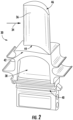
- the rotor blade 30 includes a body which includes an airfoil 36 and a shank 38.
- the airfoil 36 extends and is positioned radially outwardly from the shank 38.
- the shank 38 may include a root or dovetail 40, which may attach to the rotor disk 28 to facilitate rotation of the rotor blade 30.
- rotor blade 30 may further include one or more shrouds.
- the airfoil 36 may extend radially between a base 44 (at the intersection between the airfoil 36 and shank 38) and a tip 46.
- a tip shroud 50 may be provided at the tip 46 and may extend outwardly from the airfoil 36 in the generally axial and tangential directions.
- one or more midspan shrouds 52 may be provided between the tip 46 and the base 44 and may extend outwardly from the airfoil 36 in the generally axial and tangential directions.
- One or more cooling passages 54 may be defined in the main body, such as in the airfoil 36 as well as in the shank 38. Each cooling passage 54 may extend radially through the main body, such as through the airfoil 36 (as shown) and/or the shank 38. Additionally, one or more cooling passages 54 may be connected to form a cooling circuit.
- FIG. 3 illustrates a first cooling circuit 56 and a second cooling circuit 58, each of which includes a plurality of connected cooling passages 54.
- a cooling medium may be flowed through the cooling passages 54 to cool the main body and rotor blade 30 during operation.
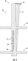
- Damping passage 60 extends and is defined radially through the entire main body or only a portion thereof. For example, as discussed, at least a portion of (which may be the entire) damping passage 60 may extend and be defined through the airfoil 36. In some embodiments, as illustrated in FIG. 4 , the portion of the damping passage 60 extending and defined through the airfoil 36 may extend from the base 44 through the tip 46. In other embodiments, as illustrated in FIG. 5 , the damping passage 60 extends radially through only a portion of the airfoil 36 and does not extend to the tip 46.
- a plug 62 may be provided and disposed within the damping passage 60 at the tip 46 or at another location in the damping passage 60.
- the plug 62 may, for example, be brazed, welded, threadably engaged, or otherwise fastened in place at the tip 46 or at another location in the damping passage 60.
- the plug 62 may be provided such that the damping passage 60 is not open externally to the rotor blade 30.
- the damping passage 60 is a single, unimpeded passageway.
- the damping passage 60 may be segmented into one or more passage segments. This may allow for multiple independent damper stacks 70 (as discussed herein) to be utilized in a given damping passage 60.
- a static insert 64 may be disposed within the damping passage 60.
- the static insert 64 may be provided in the damping passage 60 during casting or other formation of the rotor blade 30 or may be inserted into the damping passage 60 after formation of the rotor blade 30, such as by drilling an access hole 66 into the rotor blade 30 and inserting the static insert 64 through the access hole 66 into the damping passage 60.
- the access hole 66 may be formed at least partially through the midspan shroud 52.
- each damper stack 70 is disposed within a damping passage 60.
- Each damper stack 70 includes a plurality of damper pins 72.
- Each damper pin 72 is in contact with a neighboring damper pin 72 in the damper stack 70 and may further be in contact with walls defining the damping passage 60.
- damper stacks 70 in accordance with the present disclosure advantageously provides improved damping of rotor blades 30 in accordance with the present disclosure.
- the damper stacks 70 operate to dampen the absolute motion of the individual rotor blades 30 regardless of the relative motion between neighboring blades.
- Such damper stacks 70 can, for example, advantageously dampen the absolute vibratory and/or bending motion of individual rotor blades 30.
- damper stacks 70 in accordance with the present disclosure advantageously include a plurality of damper pins 72 arranged end-to-end in a co-axial relationship with a longitudinal axis of the damping passage 60.
- the primary damping of damper stacks 70 is due to the contact between the pins 72 of the damper stack 70.
- the damper pins 72 contact the sidewalls defining the damping passage 60, which also provides damping.
- One or more damper stacks 70 is/are disposed within a damping passage 60.
- a damping passage 60 In some embodiments, as illustrated in FIGS. 3 through 5 , only a single damper stack 70 is disposed in a damping passage 60. In other embodiments, as illustrated in FIG. 6 , a plurality of damper stacks 70 may be disposed in a damping passage 60. In the embodiment illustrated in FIG. 6 , a static insert 64 is disposed between neighboring damper stacks 70 of the plurality of damper stacks 70, thereby partitioning the neighboring damper stacks 70 into individual passage segments.
- the plurality of damper pins 72 includes a first damper pin 72' and a second damper pin 72", each of which extends between a first end 74 and a second end 76.
- the first end 74 of the first damper pin 72' contacts the second end 76 of the second damper pin 72".
- the second end 76 of the first damper pin 72' may contact another neighboring damper pin 72, and/or the first end 74 of the second damper pin 72" may contact yet another neighboring damper pin 72.
- the ends 74, 76 of the neighboring damper pins 72 may have suitable shapes, which provide such primary damping.
- the neighboring ends 74, 76 of neighboring damper pins 72 have complementary spherical shapes. As illustrated in FIGS. 8 and 9 , the first end 74 of the first damper pin 72' has an outward (i.e. convex) spherical shape, and the second end 76 of the second damper pin 72" has an inward (i.e. concave) spherical shape, or vice versa.
- other suitable complementary shapes such as conical, domed, etc., which provide suitable damping, may be utilized.
- the neighboring ends 74, 76 of neighboring damper pins 72 may have mirrored shapes.
- the first end 74 of the first damper pin 72' and the second end 76 of the second damper pin 72" may be flat surfaces that abut against each other.
- other suitable end 74, 76 shapes may be utilized, provided such shapes provide suitable primary damping.
- Damper pins 72 may, in some embodiments as illustrated, have generally oval or round cross-sectional profiles. Alternatively, other suitably-shaped cross-sectional profiles may be utilized. The cross-sectional profile may be constant or may vary along the length 73 of the damper pin 72. Further, damper pins 72 may have any suitable cross-sectional sizes. Still further, damper pins 72 may be formed from any suitable materials. The shapes, sizes, and/or materials may be identical for the plurality of damper pins 72 in a damper stack 70 or may vary for one or more of the damper pins 72 within a damper stack 70.
- each of the plurality of damper pins 72 may have a length 73.
- the lengths 73 of the damper pins 72 in a damper stack 70 may be identical.
- the respective lengths 73 of the first and second damper pins 72', 72" may be identical.
- the lengths 73 of one or more damper pins 72 in a damper stack 70 may be different from other damper pins 72 in the stack.
- the length 73 of the first damper pin 72' may be different from the length 73 of the second damper pin 72".
- damper pins 72 and damper stacks 70 may be utilized in damping passages 60 that are separate and independent from the cooling passages 54.
- damper pins 72 and damper stacks 70 in accordance with the present disclosure may be solid, such that no internal passage is defined therethrough, and these solid damper pins 72 and damper stacks 70 may be utilized in damping passages 60 that are or are not cooling passages 54.
- a wire may extend through one or more or more damper pins 72 of the damper stack 70.
- the wire may extend through the internal passages 78 or through separately defined internal passages, thus leaving passages 78 empty.
- the wire may generally join the damper pins 72 together.
- other suitable components may be utilized to join the damper pins 72 together, or the damper pins 72 may not be joined together.
Landscapes
- Engineering & Computer Science (AREA)
- Mechanical Engineering (AREA)
- General Engineering & Computer Science (AREA)
- Chemical & Material Sciences (AREA)
- Combustion & Propulsion (AREA)
- Turbine Rotor Nozzle Sealing (AREA)
Claims (10)
- Aube de rotor (26, 30) pour une turbomachine, l'aube de rotor (26, 30) comprenant :un corps principal comprenant une tige (38) et un profil aérodynamique (36) s'étendant radialement vers l'extérieur depuis la tige (38) ;un passage d'amortissement (60) défini dans le corps principal, le passage d'amortissement (60) s'étendant radialement à travers le corps principal ; etun empilement d'amortisseurs (70) disposé dans le passage d'amortissement (60), l'empilement d'amortisseurs (70) comprenant une pluralité de goupilles d'amortissement (72), chacune de la pluralité de goupilles d'amortissement (72) étant en contact avec une goupille d'amortissement voisine,dans laquelle la pluralité de goupilles d'amortissement (72) comprend une première goupille d'amortissement (72') et une seconde goupille d'amortissement (72"), dans laquelle chacune de la pluralité de goupilles d'amortissement (72) s'étend entre une première extrémité (74) et une seconde extrémité (76), dans laquelle la première extrémité (74) de la première goupille d'amortissement (72') entre en contact avec la seconde extrémité (76) de la seconde goupille d'amortissement (72"), caractérisée en ce que la première extrémité (74) de la première goupilled'amortissement (72') a une forme sphérique extérieure et la seconde extrémité (76) de la seconde goupille d'amortissement (72") a une forme sphérique intérieure.
- Aube de rotor (26, 30) selon la revendication 1, dans laquelle une longueur (73) de chacune de la pluralité de goupilles d'amortissement (72) est définie entre la première extrémité (74) et la seconde extrémité (76) de la goupille d'amortissement, et dans laquelle la longueur (73) de la première goupille d'amortissement (72') est différente de la longueur (73) de la seconde goupille d'amortissement (72").
- Aube de rotor (26, 30) selon l'une quelconque des revendications 1 et 2, dans laquelle chacune de la pluralité de goupilles d'amortissement (72) a un profil de section transversale creux.
- Aube de rotor (26, 30) selon l'une quelconque des revendications 1 à 3, dans laquelle l'empilement d'amortisseurs (70) est une pluralité d'empilements d'amortisseurs (70), chacun de la pluralité d'empilements d'amortisseurs (70) étant disposé dans le passage d'amortissement (60).
- Aube de rotor (26, 30) selon la revendication 4, comprenant en outre un insert statique (64) disposé dans le passage d'amortissement (60) entre des empilements d'amortisseurs voisins (70) de la pluralité d'empilements d'amortisseurs (70).
- Aube de rotor (26, 30) selon l'une quelconque des revendications 1 à 5, dans laquelle le passage d'amortissement (60) ne s'étend radialement qu'à travers une partie du profil aérodynamique (36).
- Aube de rotor (26, 30) selon l'une quelconque des revendications 1 à 6, dans laquelle le profil aérodynamique (36) s'étend radialement entre une base (44) et une pointe (46), dans laquelle le passage d'amortissement (60) est défini à travers la pointe (46), et dans laquelle un bouchon (62) est disposé dans le passage d'amortissement (60) au niveau de la pointe (46).
- Turbomachine, comprenant :une section de compresseur (14) ;une section de chambre de combustion (16) ;une section de turbine (18) ; etune pluralité d'aubes de rotor (26, 30) prévues dans au moins l'une parmi la section decompresseur (14) ou la section de turbine (18), chacune de la pluralité d'aubes de rotor (26, 30) comprenant une aube de rotor (26, 30) selon l'une quelconque des revendications 1 à 9.
- Turbomachine selon la revendication 10, dans laquelle la pluralité d'aubes de rotor (30) sont prévues dans une section de turbine (18) de la turbomachine.
- Turbomachine selon la revendication 10 ou 11, dans laquelle la turbomachine est une turbine à gaz (10).
Applications Claiming Priority (1)
| Application Number | Priority Date | Filing Date | Title |
|---|---|---|---|
| US16/708,999 US11187089B2 (en) | 2019-12-10 | 2019-12-10 | Damper stacks for turbomachine rotor blades |
Publications (2)
| Publication Number | Publication Date |
|---|---|
| EP3835548A1 EP3835548A1 (fr) | 2021-06-16 |
| EP3835548B1 true EP3835548B1 (fr) | 2023-05-10 |
Family
ID=73597845
Family Applications (1)
| Application Number | Title | Priority Date | Filing Date |
|---|---|---|---|
| EP20209646.7A Active EP3835548B1 (fr) | 2019-12-10 | 2020-11-24 | Aube rotorique pour une turbomachine et turbomachine |
Country Status (4)
| Country | Link |
|---|---|
| US (1) | US11187089B2 (fr) |
| EP (1) | EP3835548B1 (fr) |
| JP (1) | JP2021092222A (fr) |
| CN (1) | CN112943376A (fr) |
Families Citing this family (6)
| Publication number | Priority date | Publication date | Assignee | Title |
|---|---|---|---|---|
| US11572791B1 (en) | 2022-01-12 | 2023-02-07 | General Electric Company | Vibration damping system for turbine nozzle or blade using damper pins with wire mesh members 1HEREON |
| US11519276B1 (en) | 2022-01-12 | 2022-12-06 | General Electric Company | Vibration damping system for turbine blade or nozzle, retention system therefor, and method of assembly |
| US11634991B1 (en) | 2022-01-12 | 2023-04-25 | General Electric Company | Vibration damping system for turbine nozzle or blade using elongated body and wire mesh member |
| US11976565B2 (en) | 2022-07-27 | 2024-05-07 | Ge Infrastructure Technology Llc | Nested damper pin and vibration dampening system for turbine nozzle or blade |
| US12071862B2 (en) * | 2022-07-27 | 2024-08-27 | Ge Infrastructure Technology Llc | Vibration damping system for turbine nozzle or blade using stacked plate members |
| US12006831B1 (en) * | 2023-06-29 | 2024-06-11 | Ge Infrastructure Technology Llc | Damper element with spring-suspended bearing member for vibration dampening system for turbine blade |
Citations (1)
| Publication number | Priority date | Publication date | Assignee | Title |
|---|---|---|---|---|
| US20190017402A1 (en) * | 2016-01-12 | 2019-01-17 | Siemens Aktiengesellschaft | Flexible damper for turbine blades |
Family Cites Families (20)
| Publication number | Priority date | Publication date | Assignee | Title |
|---|---|---|---|---|
| FR981599A (fr) | 1948-12-31 | 1951-05-28 | Dispositif amortisseur de vibrations | |
| US2999669A (en) | 1958-11-21 | 1961-09-12 | Westinghouse Electric Corp | Damping apparatus |
| US5820343A (en) * | 1995-07-31 | 1998-10-13 | United Technologies Corporation | Airfoil vibration damping device |
| US7121801B2 (en) * | 2004-02-13 | 2006-10-17 | United Technologies Corporation | Cooled rotor blade with vibration damping device |
| US7762780B2 (en) * | 2007-01-25 | 2010-07-27 | Siemens Energy, Inc. | Blade assembly in a combustion turbo-machine providing reduced concentration of mechanical stress and a seal between adjacent assemblies |
| US8267662B2 (en) | 2007-12-13 | 2012-09-18 | General Electric Company | Monolithic and bi-metallic turbine blade dampers and method of manufacture |
| US8066479B2 (en) * | 2010-04-05 | 2011-11-29 | Pratt & Whitney Rocketdyne, Inc. | Non-integral platform and damper for an airfoil |
| US8672626B2 (en) * | 2010-04-21 | 2014-03-18 | United Technologies Corporation | Engine assembled seal |
| US8876478B2 (en) * | 2010-11-17 | 2014-11-04 | General Electric Company | Turbine blade combined damper and sealing pin and related method |
| US9175570B2 (en) * | 2012-04-24 | 2015-11-03 | United Technologies Corporation | Airfoil including member connected by articulated joint |
| US9309782B2 (en) * | 2012-09-14 | 2016-04-12 | General Electric Company | Flat bottom damper pin for turbine blades |
| US9151165B2 (en) * | 2012-10-22 | 2015-10-06 | United Technologies Corporation | Reversible blade damper |
| JP5705810B2 (ja) | 2012-10-26 | 2015-04-22 | 三菱重工業株式会社 | 塔状構造物、及び、塔状構造物の施工方法 |
| US9194238B2 (en) * | 2012-11-28 | 2015-11-24 | General Electric Company | System for damping vibrations in a turbine |
| CN105308315B (zh) | 2013-06-11 | 2018-09-11 | 维斯塔斯风力系统有限公司 | 具有阻尼器的风轮机塔架 |
| EP3091181A1 (fr) | 2015-05-05 | 2016-11-09 | MTU Aero Engines GmbH | Aube pour une turbomachine et procédé de fabrication associé |
| US10443408B2 (en) * | 2015-09-03 | 2019-10-15 | General Electric Company | Damper pin for a turbine blade |
| US20170067347A1 (en) * | 2015-09-03 | 2017-03-09 | General Electric Company | Slotted damper pin for a turbine blade |
| US10385701B2 (en) * | 2015-09-03 | 2019-08-20 | General Electric Company | Damper pin for a turbine blade |
| JP6802729B2 (ja) | 2017-02-22 | 2020-12-16 | 三菱パワー株式会社 | 回転機械の翼のダンパ装置及び回転機械 |
-
2019
- 2019-12-10 US US16/708,999 patent/US11187089B2/en active Active
-
2020
- 2020-11-24 EP EP20209646.7A patent/EP3835548B1/fr active Active
- 2020-11-24 JP JP2020194371A patent/JP2021092222A/ja active Pending
- 2020-12-03 CN CN202011397049.7A patent/CN112943376A/zh active Pending
Patent Citations (1)
| Publication number | Priority date | Publication date | Assignee | Title |
|---|---|---|---|---|
| US20190017402A1 (en) * | 2016-01-12 | 2019-01-17 | Siemens Aktiengesellschaft | Flexible damper for turbine blades |
Also Published As
| Publication number | Publication date |
|---|---|
| EP3835548A1 (fr) | 2021-06-16 |
| US20210172325A1 (en) | 2021-06-10 |
| US11187089B2 (en) | 2021-11-30 |
| CN112943376A (zh) | 2021-06-11 |
| JP2021092222A (ja) | 2021-06-17 |
Similar Documents
| Publication | Publication Date | Title |
|---|---|---|
| EP3835548B1 (fr) | Aube rotorique pour une turbomachine et turbomachine | |
| EP3835550B1 (fr) | Aube rotorique pour une turbomachine et turbomachine | |
| EP3139003B1 (fr) | Goupille amortissante pour aubes de turbine et moteur à turbine associé | |
| CN106499442B (zh) | 用于涡轮叶片的阻尼器销 | |
| US20150204237A1 (en) | Turbine blade and method for enhancing life of the turbine blade | |
| US11739645B2 (en) | Vibrational dampening elements | |
| EP3415719B1 (fr) | Structure de refroidissement d'aube de turbomachine | |
| EP3138999B1 (fr) | Goupille amortissante pour amortir des aubes de turbine adjacentes et moteur à turbine | |
| EP3260661B1 (fr) | Profil aérodynamique ayant un découplage de fente variable | |
| CN106499444B (zh) | 用于涡轮叶片的阻尼器销 | |
| JP6558827B2 (ja) | タービンブレードのミッドスパンシュラウド組立体 | |
| US20170191366A1 (en) | Slotted damper pin for a turbine blade | |
| EP3978727B1 (fr) | Aube rotorique avec structure d'amortissement | |
| EP3885533B1 (fr) | Aube rotorique pour une turbomachine et turbomachine associée | |
| US11767765B2 (en) | Glass viscous damper |
Legal Events
| Date | Code | Title | Description |
|---|---|---|---|
| PUAI | Public reference made under article 153(3) epc to a published international application that has entered the european phase |
Free format text: ORIGINAL CODE: 0009012 |
|
| STAA | Information on the status of an ep patent application or granted ep patent |
Free format text: STATUS: THE APPLICATION HAS BEEN PUBLISHED |
|
| AK | Designated contracting states |
Kind code of ref document: A1 Designated state(s): AL AT BE BG CH CY CZ DE DK EE ES FI FR GB GR HR HU IE IS IT LI LT LU LV MC MK MT NL NO PL PT RO RS SE SI SK SM TR |
|
| STAA | Information on the status of an ep patent application or granted ep patent |
Free format text: STATUS: REQUEST FOR EXAMINATION WAS MADE |
|
| 17P | Request for examination filed |
Effective date: 20211214 |
|
| RBV | Designated contracting states (corrected) |
Designated state(s): AL AT BE BG CH CY CZ DE DK EE ES FI FR GB GR HR HU IE IS IT LI LT LU LV MC MK MT NL NO PL PT RO RS SE SI SK SM TR |
|
| STAA | Information on the status of an ep patent application or granted ep patent |
Free format text: STATUS: EXAMINATION IS IN PROGRESS |
|
| 17Q | First examination report despatched |
Effective date: 20220602 |
|
| RIC1 | Information provided on ipc code assigned before grant |
Ipc: F01D 5/16 20060101AFI20221215BHEP |
|
| GRAP | Despatch of communication of intention to grant a patent |
Free format text: ORIGINAL CODE: EPIDOSNIGR1 |
|
| STAA | Information on the status of an ep patent application or granted ep patent |
Free format text: STATUS: GRANT OF PATENT IS INTENDED |
|
| INTG | Intention to grant announced |
Effective date: 20230127 |
|
| GRAS | Grant fee paid |
Free format text: ORIGINAL CODE: EPIDOSNIGR3 |
|
| GRAA | (expected) grant |
Free format text: ORIGINAL CODE: 0009210 |
|
| STAA | Information on the status of an ep patent application or granted ep patent |
Free format text: STATUS: THE PATENT HAS BEEN GRANTED |
|
| AK | Designated contracting states |
Kind code of ref document: B1 Designated state(s): AL AT BE BG CH CY CZ DE DK EE ES FI FR GB GR HR HU IE IS IT LI LT LU LV MC MK MT NL NO PL PT RO RS SE SI SK SM TR |
|
| REG | Reference to a national code |
Ref country code: GB Ref legal event code: FG4D |
|
| REG | Reference to a national code |
Ref country code: AT Ref legal event code: REF Ref document number: 1566860 Country of ref document: AT Kind code of ref document: T Effective date: 20230515 Ref country code: CH Ref legal event code: EP |
|
| REG | Reference to a national code |
Ref country code: DE Ref legal event code: R096 Ref document number: 602020010699 Country of ref document: DE |
|
| REG | Reference to a national code |
Ref country code: IE Ref legal event code: FG4D |
|
| REG | Reference to a national code |
Ref country code: LT Ref legal event code: MG9D |
|
| REG | Reference to a national code |
Ref country code: NL Ref legal event code: MP Effective date: 20230510 |
|
| REG | Reference to a national code |
Ref country code: AT Ref legal event code: MK05 Ref document number: 1566860 Country of ref document: AT Kind code of ref document: T Effective date: 20230510 |
|
| PG25 | Lapsed in a contracting state [announced via postgrant information from national office to epo] |
Ref country code: SE Free format text: LAPSE BECAUSE OF FAILURE TO SUBMIT A TRANSLATION OF THE DESCRIPTION OR TO PAY THE FEE WITHIN THE PRESCRIBED TIME-LIMIT Effective date: 20230510 Ref country code: PT Free format text: LAPSE BECAUSE OF FAILURE TO SUBMIT A TRANSLATION OF THE DESCRIPTION OR TO PAY THE FEE WITHIN THE PRESCRIBED TIME-LIMIT Effective date: 20230911 Ref country code: NO Free format text: LAPSE BECAUSE OF FAILURE TO SUBMIT A TRANSLATION OF THE DESCRIPTION OR TO PAY THE FEE WITHIN THE PRESCRIBED TIME-LIMIT Effective date: 20230810 Ref country code: NL Free format text: LAPSE BECAUSE OF FAILURE TO SUBMIT A TRANSLATION OF THE DESCRIPTION OR TO PAY THE FEE WITHIN THE PRESCRIBED TIME-LIMIT Effective date: 20230510 Ref country code: ES Free format text: LAPSE BECAUSE OF FAILURE TO SUBMIT A TRANSLATION OF THE DESCRIPTION OR TO PAY THE FEE WITHIN THE PRESCRIBED TIME-LIMIT Effective date: 20230510 Ref country code: AT Free format text: LAPSE BECAUSE OF FAILURE TO SUBMIT A TRANSLATION OF THE DESCRIPTION OR TO PAY THE FEE WITHIN THE PRESCRIBED TIME-LIMIT Effective date: 20230510 |
|
| REG | Reference to a national code |
Ref country code: DE Ref legal event code: R081 Ref document number: 602020010699 Country of ref document: DE Owner name: GENERAL ELECTRIC TECHNOLOGY GMBH, CH Free format text: FORMER OWNER: GENERAL ELECTRIC CO., SCHENECTADY, NY, US |
|
| PG25 | Lapsed in a contracting state [announced via postgrant information from national office to epo] |
Ref country code: RS Free format text: LAPSE BECAUSE OF FAILURE TO SUBMIT A TRANSLATION OF THE DESCRIPTION OR TO PAY THE FEE WITHIN THE PRESCRIBED TIME-LIMIT Effective date: 20230510 Ref country code: PL Free format text: LAPSE BECAUSE OF FAILURE TO SUBMIT A TRANSLATION OF THE DESCRIPTION OR TO PAY THE FEE WITHIN THE PRESCRIBED TIME-LIMIT Effective date: 20230510 Ref country code: LV Free format text: LAPSE BECAUSE OF FAILURE TO SUBMIT A TRANSLATION OF THE DESCRIPTION OR TO PAY THE FEE WITHIN THE PRESCRIBED TIME-LIMIT Effective date: 20230510 Ref country code: LT Free format text: LAPSE BECAUSE OF FAILURE TO SUBMIT A TRANSLATION OF THE DESCRIPTION OR TO PAY THE FEE WITHIN THE PRESCRIBED TIME-LIMIT Effective date: 20230510 Ref country code: IS Free format text: LAPSE BECAUSE OF FAILURE TO SUBMIT A TRANSLATION OF THE DESCRIPTION OR TO PAY THE FEE WITHIN THE PRESCRIBED TIME-LIMIT Effective date: 20230910 Ref country code: HR Free format text: LAPSE BECAUSE OF FAILURE TO SUBMIT A TRANSLATION OF THE DESCRIPTION OR TO PAY THE FEE WITHIN THE PRESCRIBED TIME-LIMIT Effective date: 20230510 Ref country code: GR Free format text: LAPSE BECAUSE OF FAILURE TO SUBMIT A TRANSLATION OF THE DESCRIPTION OR TO PAY THE FEE WITHIN THE PRESCRIBED TIME-LIMIT Effective date: 20230811 |
|
| RAP2 | Party data changed (patent owner data changed or rights of a patent transferred) |
Owner name: GENERAL ELECTRIC TECHNOLOGY GMBH |
|
| PG25 | Lapsed in a contracting state [announced via postgrant information from national office to epo] |
Ref country code: FI Free format text: LAPSE BECAUSE OF FAILURE TO SUBMIT A TRANSLATION OF THE DESCRIPTION OR TO PAY THE FEE WITHIN THE PRESCRIBED TIME-LIMIT Effective date: 20230510 |
|
| PG25 | Lapsed in a contracting state [announced via postgrant information from national office to epo] |
Ref country code: SK Free format text: LAPSE BECAUSE OF FAILURE TO SUBMIT A TRANSLATION OF THE DESCRIPTION OR TO PAY THE FEE WITHIN THE PRESCRIBED TIME-LIMIT Effective date: 20230510 |
|
| PG25 | Lapsed in a contracting state [announced via postgrant information from national office to epo] |
Ref country code: SM Free format text: LAPSE BECAUSE OF FAILURE TO SUBMIT A TRANSLATION OF THE DESCRIPTION OR TO PAY THE FEE WITHIN THE PRESCRIBED TIME-LIMIT Effective date: 20230510 Ref country code: SK Free format text: LAPSE BECAUSE OF FAILURE TO SUBMIT A TRANSLATION OF THE DESCRIPTION OR TO PAY THE FEE WITHIN THE PRESCRIBED TIME-LIMIT Effective date: 20230510 Ref country code: RO Free format text: LAPSE BECAUSE OF FAILURE TO SUBMIT A TRANSLATION OF THE DESCRIPTION OR TO PAY THE FEE WITHIN THE PRESCRIBED TIME-LIMIT Effective date: 20230510 Ref country code: EE Free format text: LAPSE BECAUSE OF FAILURE TO SUBMIT A TRANSLATION OF THE DESCRIPTION OR TO PAY THE FEE WITHIN THE PRESCRIBED TIME-LIMIT Effective date: 20230510 Ref country code: DK Free format text: LAPSE BECAUSE OF FAILURE TO SUBMIT A TRANSLATION OF THE DESCRIPTION OR TO PAY THE FEE WITHIN THE PRESCRIBED TIME-LIMIT Effective date: 20230510 Ref country code: CZ Free format text: LAPSE BECAUSE OF FAILURE TO SUBMIT A TRANSLATION OF THE DESCRIPTION OR TO PAY THE FEE WITHIN THE PRESCRIBED TIME-LIMIT Effective date: 20230510 |
|
| PGFP | Annual fee paid to national office [announced via postgrant information from national office to epo] |
Ref country code: IT Payment date: 20231130 Year of fee payment: 4 Ref country code: DE Payment date: 20231019 Year of fee payment: 4 |
|
| REG | Reference to a national code |
Ref country code: DE Ref legal event code: R097 Ref document number: 602020010699 Country of ref document: DE |
|
| PLBE | No opposition filed within time limit |
Free format text: ORIGINAL CODE: 0009261 |
|
| STAA | Information on the status of an ep patent application or granted ep patent |
Free format text: STATUS: NO OPPOSITION FILED WITHIN TIME LIMIT |
|
| 26N | No opposition filed |
Effective date: 20240213 |
|
| PG25 | Lapsed in a contracting state [announced via postgrant information from national office to epo] |
Ref country code: SI Free format text: LAPSE BECAUSE OF FAILURE TO SUBMIT A TRANSLATION OF THE DESCRIPTION OR TO PAY THE FEE WITHIN THE PRESCRIBED TIME-LIMIT Effective date: 20230510 |
|
| PG25 | Lapsed in a contracting state [announced via postgrant information from national office to epo] |
Ref country code: SI Free format text: LAPSE BECAUSE OF FAILURE TO SUBMIT A TRANSLATION OF THE DESCRIPTION OR TO PAY THE FEE WITHIN THE PRESCRIBED TIME-LIMIT Effective date: 20230510 |
|
| REG | Reference to a national code |
Ref country code: CH Ref legal event code: PL |
|
| PG25 | Lapsed in a contracting state [announced via postgrant information from national office to epo] |
Ref country code: MC Free format text: LAPSE BECAUSE OF FAILURE TO SUBMIT A TRANSLATION OF THE DESCRIPTION OR TO PAY THE FEE WITHIN THE PRESCRIBED TIME-LIMIT Effective date: 20230510 |
|
| PG25 | Lapsed in a contracting state [announced via postgrant information from national office to epo] |
Ref country code: LU Free format text: LAPSE BECAUSE OF NON-PAYMENT OF DUE FEES Effective date: 20231124 |
|
| PG25 | Lapsed in a contracting state [announced via postgrant information from national office to epo] |
Ref country code: CH Free format text: LAPSE BECAUSE OF NON-PAYMENT OF DUE FEES Effective date: 20231130 |
|
| PG25 | Lapsed in a contracting state [announced via postgrant information from national office to epo] |
Ref country code: MC Free format text: LAPSE BECAUSE OF FAILURE TO SUBMIT A TRANSLATION OF THE DESCRIPTION OR TO PAY THE FEE WITHIN THE PRESCRIBED TIME-LIMIT Effective date: 20230510 Ref country code: LU Free format text: LAPSE BECAUSE OF NON-PAYMENT OF DUE FEES Effective date: 20231124 Ref country code: CH Free format text: LAPSE BECAUSE OF NON-PAYMENT OF DUE FEES Effective date: 20231130 |
|
| REG | Reference to a national code |
Ref country code: BE Ref legal event code: MM Effective date: 20231130 |
|
| REG | Reference to a national code |
Ref country code: IE Ref legal event code: MM4A |
|
| PG25 | Lapsed in a contracting state [announced via postgrant information from national office to epo] |
Ref country code: IE Free format text: LAPSE BECAUSE OF NON-PAYMENT OF DUE FEES Effective date: 20231124 |
|
| PG25 | Lapsed in a contracting state [announced via postgrant information from national office to epo] |
Ref country code: BE Free format text: LAPSE BECAUSE OF NON-PAYMENT OF DUE FEES Effective date: 20231130 |
|
| PG25 | Lapsed in a contracting state [announced via postgrant information from national office to epo] |
Ref country code: FR Free format text: LAPSE BECAUSE OF NON-PAYMENT OF DUE FEES Effective date: 20231130 |