EP3835513B1 - Safety device for struts - Google Patents
Safety device for struts Download PDFInfo
- Publication number
- EP3835513B1 EP3835513B1 EP19383096.5A EP19383096A EP3835513B1 EP 3835513 B1 EP3835513 B1 EP 3835513B1 EP 19383096 A EP19383096 A EP 19383096A EP 3835513 B1 EP3835513 B1 EP 3835513B1
- Authority
- EP
- European Patent Office
- Prior art keywords
- safety device
- base
- struts
- extremities
- outer tube
- Prior art date
- Legal status (The legal status is an assumption and is not a legal conclusion. Google has not performed a legal analysis and makes no representation as to the accuracy of the status listed.)
- Active
Links
- 238000000926 separation method Methods 0.000 claims description 4
- 230000000284 resting effect Effects 0.000 claims description 3
- 238000009415 formwork Methods 0.000 description 5
- 230000007246 mechanism Effects 0.000 description 4
- 238000011084 recovery Methods 0.000 description 3
- 238000006073 displacement reaction Methods 0.000 description 2
- 238000004519 manufacturing process Methods 0.000 description 2
- 238000010276 construction Methods 0.000 description 1
- 230000001419 dependent effect Effects 0.000 description 1
- 230000002542 deteriorative effect Effects 0.000 description 1
- 230000037431 insertion Effects 0.000 description 1
- 238000003780 insertion Methods 0.000 description 1
Images


Classifications
-
- E—FIXED CONSTRUCTIONS
- E04—BUILDING
- E04G—SCAFFOLDING; FORMS; SHUTTERING; BUILDING IMPLEMENTS OR AIDS, OR THEIR USE; HANDLING BUILDING MATERIALS ON THE SITE; REPAIRING, BREAKING-UP OR OTHER WORK ON EXISTING BUILDINGS
- E04G25/00—Shores or struts; Chocks
- E04G25/04—Shores or struts; Chocks telescopic
- E04G25/06—Shores or struts; Chocks telescopic with parts held together by positive means
- E04G25/061—Shores or struts; Chocks telescopic with parts held together by positive means by pins
- E04G25/063—Shores or struts; Chocks telescopic with parts held together by positive means by pins with safety devices to avoid the accidental loss or unlocking of the pin, e.g. chains attaching the pin to the prop
-
- E—FIXED CONSTRUCTIONS
- E04—BUILDING
- E04G—SCAFFOLDING; FORMS; SHUTTERING; BUILDING IMPLEMENTS OR AIDS, OR THEIR USE; HANDLING BUILDING MATERIALS ON THE SITE; REPAIRING, BREAKING-UP OR OTHER WORK ON EXISTING BUILDINGS
- E04G25/00—Shores or struts; Chocks
- E04G25/04—Shores or struts; Chocks telescopic
- E04G25/06—Shores or struts; Chocks telescopic with parts held together by positive means
- E04G25/065—Shores or struts; Chocks telescopic with parts held together by positive means by a threaded nut
-
- E—FIXED CONSTRUCTIONS
- E04—BUILDING
- E04G—SCAFFOLDING; FORMS; SHUTTERING; BUILDING IMPLEMENTS OR AIDS, OR THEIR USE; HANDLING BUILDING MATERIALS ON THE SITE; REPAIRING, BREAKING-UP OR OTHER WORK ON EXISTING BUILDINGS
- E04G25/00—Shores or struts; Chocks
- E04G25/04—Shores or struts; Chocks telescopic
- E04G25/06—Shores or struts; Chocks telescopic with parts held together by positive means
- E04G25/066—Shores or struts; Chocks telescopic with parts held together by positive means by a wedge
-
- E—FIXED CONSTRUCTIONS
- E04—BUILDING
- E04G—SCAFFOLDING; FORMS; SHUTTERING; BUILDING IMPLEMENTS OR AIDS, OR THEIR USE; HANDLING BUILDING MATERIALS ON THE SITE; REPAIRING, BREAKING-UP OR OTHER WORK ON EXISTING BUILDINGS
- E04G25/00—Shores or struts; Chocks
- E04G25/04—Shores or struts; Chocks telescopic
- E04G25/06—Shores or struts; Chocks telescopic with parts held together by positive means
- E04G25/068—Shores or struts; Chocks telescopic with parts held together by positive means by a cam
Definitions
- a safety device supported by a strut on an external thread.
- the safety device consists of a pin, which is affixed to said device on one side, and on the other, to the telescopic tube of the strut.
- the pin is supported by a horizontal surface of the safety device, adjacent to which there is a ramp or step descending to a depression.
- the safety device is displaced horizontally by means of a blow, the pin falls from the horizontal surface into the depression, while the telescopic tube of the strut also descends as required for removing the formwork.
- the safety device comprises an internal spring that exerts a force in the direction opposite the disassembly direction.
- a safety device is the one shown in document EP1975341 .
- This safety device differs from the one described previously in that the pin is not affixed to the safety device but rather, in order to prevent the device from becoming disassembled accidentally, it has a rotational configuration in which, while in a rest condition, it blocks the displacement of the safety device. In order to unblock the safety device, the operator must first rotate the pin.
- the struts used in formwork can withstand tonnes of weight, due to which they need a reliable support mechanism, as well as a fast and convenient disassembly system for the operator, as the formwork can have hundreds or thousands of struts that need to be disassembled.
- the safety element is unreliable, or the operator needs to make significant effort either to deactivate the safety element and/or to displace the safety device to the disassembly position.
- the present invention consists of a safety device for struts intended for use in struts of the type comprising:
- the present safety device for struts comprises a base with at least one U-shaped portion, and may have other added portions, which for example close the open end.
- This base is intended, in a lock condition of the safety device, to be positioned with that portion of its extremities around the upper threaded portion of the outer tube, while being supported by the nut and by the central section of the base separated from the outer tube. Therefore, the separation between the extremities, at least in one section thereof, must be longer than the width of the outer tube to ensure it can be positioned around the upper threaded portion of the outer tube. At the same time, this separation between the extremities must be shorter than the length of the pin, in order to support the pin, as well as shorter than the width of the nut, in order to be supported by said nut.
- the novelty of the safety device for struts is defined by two peculiarities.
- the first is that the upper surface of each extremity of the base comprises an inclined portion, both inclined portions being symmetrical to each other relative to the vertical plane of symmetry of the base and the lower ends thereof being situated on the side of the central section of the base.
- the second consists of a latch, which has at least one U-shaped portion and which is affixed in an articulated manner by its central section to the central section of the base, which may freely rotate relative to an axis perpendicular to the vertical plane of symmetry of the base.
- the size of this latch is such that, in a lock condition of the safety device, the extremities thereof rest on said inclined portions to thus hold the pin supported by said inclined portions.
- at least one of the extremities thereof comprises a protrusion to facilitate the rotation of the latch from its locking position to an unlocking or opening position.
- a safety device for struts an operator can dismount the strut with only two slight taps.
- the first tap is to rotate the latch from its locking position to an unlocking position, and the next tap is to move the safety device horizontally and lower the pin. Thanks to the inclination of the inclined portions, the safety device moves and the pin is released without the need for a strong impact (or the sequence of several impacts), with the convenience that this means for the operator.
- the base of the safety device may include steps linking the lower ends of the inclined portions to lower sections, which may preferably be horizontal. This way, moving the safety device slightly is enough for releasing the pin.
- the base can comprise a protrusion to enable horizontal displacement by means of a blow of a hammer in the central section of the base.
- the central section of the latch is affixed at a height equal to or lower than the position of the extremities resting on the inclined portions. This way, the latch receives virtually no weight from the strut, and the rotation thereof from the locking position to an unlocking position requires little effort from the operator.
- the ends of the base can be previously separated from each other.
- the extremities of the base can receive a connecting piece, which closes the contour of the safety device and prevents it from coming out of the strut.
- the ends of the base are joined from the beginning, and the base can be made of one have a one-piece construction which must be inserted into the strut during the assembly thereof.
- they may comprise an upper surface that is heat-treated to be hardened.
- the present safety device for struts provides a mechanism that makes it possible to remove struts quickly and safely through operations that require little effort from the operator.
- the savings in manpower provided by the use of the safety device for struts translates into a reduction in the cost of executing the works, such that the investment that is required for using this safety device for struts is recovered very quickly.
- the present invention consists of a safety device (1, 1') for struts intended to be used with struts of the type comprising an outer tube (TE) with an upper threaded portion comprising two longitudinal and diametrically opposed slots, an inner tube (TI) telescopically housed in the outer tube (TE) comprising at least two diametrically opposed holes, a nut (N) that can be threaded to the upper threaded portion of the outer tube (TE), and a pin (P) that can be housed both in the two slots of the outer tube (TE) and in the two holes of the inner tube (TI).
- a safety device (1, 1') for struts intended to be used with struts of the type comprising an outer tube (TE) with an upper threaded portion comprising two longitudinal and diametrically opposed slots, an inner tube (TI) telescopically housed in the outer tube (TE) comprising at least two diametrically opposed holes, a nut (N) that can be threaded
- the preferred embodiments of the safety device (1, 1') for struts comprise a base (2, 2') with a U-shaped portion, with the separation between the extremities (22, 22') thereof being longer than the width of the outer tube (TE) and shorter than the length of the pin (P), as well as the width of the nut (N), in order to be supported by said nut (N).
- the extremities (22) of the base (2) comprise a connecting piece (25), which closes the contour of the safety device (1) once placed on the strut, to prevent it from coming out of the strut.
- This embodiment is suitable for struts whose tubes (TE, TI) have already been assembled.
- the extremities (22') of the base (2') are joined by an extension thereof, due to which the base can be made of one piece. This embodiment is more cost effective to manufacture, although it must be placed on the strut before the tubes (TE, TI) thereof are assembled.
- each extremity (22, 22') of the base (2) comprises an inclined portion (23), both inclined portions (23) being symmetrical to each other relative to the vertical plane of symmetry of the base (2) and the lower ends thereof being situated on the side of the central section (21) of the base (2).
- the safety device (1, 1') for struts comprises a latch (3), which has a U-shaped portion affixed in an articulated manner by its central section (31) to the central section (21) of the base (2, 2') and may freely rotate relative to an axis (A) perpendicular to the vertical plane of symmetry of the base (2, 2') shown in Figures 2, 3A and 3B .
- the size of the latch (3) is such that the extremities (32) of the latch (3) can rest on said inclined portions (23) when the central section (21) of the base (2, 2') is separated from the outer tube (TE).
- the latch holds the pin (P) over the inclined portions (23), as shown in Figure 4 .
- the base (2, 2') of the safety device (1) comprises steps that link the lower ends of the inclined portions (23) to lower sections (24), which are horizontal in these embodiments.
- the pin (P) is held in the inclined portions (23) thanks to the operation of the latch (3), the extremities (23) of which also rest on the inclined portions (23).
- the safety device (1, 1') for struts has been displaced horizontally, lowering the pin (P) to the lower sections (24) accompanied by the inner tube (TI). This way, the strut is released from the formwork it supported and can be easily recovered.
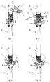
- each extremity (32) of the latch (3) comprises a protrusion (33) which can be hit upwards, as can be inferred by the position of the square face of the hammer shown in Figure 6 .
- this embodiment comprises a protrusion (20) which can be hit horizontally, as can be inferred by the position of the square face of the hammer shown in Figure 7 .
- the central section (31) of the latch (3) is affixed at a height that is slightly lower than the position of the extremities (32) resting on the inclined portions (23). This way, the latch (3) receives virtually no weight from the strut, due to which its rotation from the locking position to an unlocking position requires little effort from the operator.
- the ends of the base (2) can be previously separated from each other, as shown in Figure 8 .
- the extremities (23) of the base (2) can receive the connecting part (25), shown in Figure 9 , which closes the contour of the safety device (1) and prevents it from coming out of the strut.
- the operator can now insert the pin (P) through the corresponding slots and holes, as shown in Figure 10 , to finally place the latch (3) in its locking position, as shown in Figure 11 .
- the nut (N) can comprise a drive lever configured to thread the nut to the threaded portion of the outer tube (TE) when actuated by a user.
Landscapes
- Engineering & Computer Science (AREA)
- Architecture (AREA)
- Mechanical Engineering (AREA)
- Civil Engineering (AREA)
- Structural Engineering (AREA)
- Forms Removed On Construction Sites Or Auxiliary Members Thereof (AREA)
Description
- There are several formwork removal mechanisms or safety devices for struts known in the state of the art. For example, document
FR2712017 - Another example of a safety device is the one shown in document
EP1975341 . This safety device differs from the one described previously in that the pin is not affixed to the safety device but rather, in order to prevent the device from becoming disassembled accidentally, it has a rotational configuration in which, while in a rest condition, it blocks the displacement of the safety device. In order to unblock the safety device, the operator must first rotate the pin. - It should be noted that the struts used in formwork can withstand tonnes of weight, due to which they need a reliable support mechanism, as well as a fast and convenient disassembly system for the operator, as the formwork can have hundreds or thousands of struts that need to be disassembled. However, as can be inferred from the mechanisms known in the state of the art, either the safety element is unreliable, or the operator needs to make significant effort either to deactivate the safety element and/or to displace the safety device to the disassembly position.
- Therefore, there is still a need for a robust safety device which is cost effective to manufacture and that can be quickly and conveniently mounted and dismounted by an operator. This and other objects are achieved by a safety device according to
claim 1 and thereupon dependent claims. - The present invention consists of a safety device for struts intended for use in struts of the type comprising:
- an outer tube with an upper threaded portion in which there are two longitudinal and diametrically opposed slots,
- an inner tube telescopically housed in the outer tube and comprising at least two diametrically opposed holes,
- an internally threaded nut or bushing, which can be threaded to the upper threaded portion of the outer tube, and
- a pin that can be housed both in the two slots of the outer tube and in the two holes of the inner tube.
- The present safety device for struts comprises a base with at least one U-shaped portion, and may have other added portions, which for example close the open end. This base is intended, in a lock condition of the safety device, to be positioned with that portion of its extremities around the upper threaded portion of the outer tube, while being supported by the nut and by the central section of the base separated from the outer tube. Therefore, the separation between the extremities, at least in one section thereof, must be longer than the width of the outer tube to ensure it can be positioned around the upper threaded portion of the outer tube. At the same time, this separation between the extremities must be shorter than the length of the pin, in order to support the pin, as well as shorter than the width of the nut, in order to be supported by said nut.
- The novelty of the safety device for struts is defined by two peculiarities. The first is that the upper surface of each extremity of the base comprises an inclined portion, both inclined portions being symmetrical to each other relative to the vertical plane of symmetry of the base and the lower ends thereof being situated on the side of the central section of the base. The second consists of a latch, which has at least one U-shaped portion and which is affixed in an articulated manner by its central section to the central section of the base, which may freely rotate relative to an axis perpendicular to the vertical plane of symmetry of the base. The size of this latch is such that, in a lock condition of the safety device, the extremities thereof rest on said inclined portions to thus hold the pin supported by said inclined portions. In turn, at least one of the extremities thereof comprises a protrusion to facilitate the rotation of the latch from its locking position to an unlocking or opening position.
- Thanks to this configuration of a safety device for struts, an operator can dismount the strut with only two slight taps. The first tap is to rotate the latch from its locking position to an unlocking position, and the next tap is to move the safety device horizontally and lower the pin. Thanks to the inclination of the inclined portions, the safety device moves and the pin is released without the need for a strong impact (or the sequence of several impacts), with the convenience that this means for the operator.
- Optionally, the base of the safety device may include steps linking the lower ends of the inclined portions to lower sections, which may preferably be horizontal. This way, moving the safety device slightly is enough for releasing the pin.
- The base can comprise a protrusion to enable horizontal displacement by means of a blow of a hammer in the central section of the base.
- Preferably, the central section of the latch is affixed at a height equal to or lower than the position of the extremities resting on the inclined portions. This way, the latch receives virtually no weight from the strut, and the rotation thereof from the locking position to an unlocking position requires little effort from the operator.
- In order to place the safety device for struts on a strut that has already been mounted, the ends of the base can be previously separated from each other. In this case, once placed on the strut, the extremities of the base can receive a connecting piece, which closes the contour of the safety device and prevents it from coming out of the strut. In another possible embodiment, the ends of the base are joined from the beginning, and the base can be made of one have a one-piece construction which must be inserted into the strut during the assembly thereof.
- Preferably, to prevent the inclined portions from deteriorating due to the pressure exerted by the pin, they may comprise an upper surface that is heat-treated to be hardened.
- The present safety device for struts provides a mechanism that makes it possible to remove struts quickly and safely through operations that require little effort from the operator. In turn, the savings in manpower provided by the use of the safety device for struts translates into a reduction in the cost of executing the works, such that the investment that is required for using this safety device for struts is recovered very quickly.
- These and other features and advantages of the safety device for struts object of the present invention will be evident from the description of a preferred, but not exclusive, embodiment, which is illustrated by way of a nonlimiting example in the drawings provided herein:
-
-
Figure 1 .- A perspective view of a strut in an embodiment of the present safety device for struts. -
Figure 2 .- An extension of the detail II indicated inFigure 1 . -
Figure 3A .- A plan view of a first embodiment of the present safety device for struts. -
Figure 3B .- A plan view of a second embodiment of the present safety device for struts. -
Figure 3C .- A side view of the second embodiment of the present safety device for struts. -
Figure 4 .- A side view of the first embodiment of the safety device in the lock condition of the strut. -
Figure 5 .- A side view of the first embodiment of the safety device in the recovery condition of the strut. -
Figure 6 .- A perspective view of the first embodiment of the safety device in the lock condition of the strut. -
Figure 7 .- A perspective view of the first embodiment of the safety device with the latch in an unlocking position, prior to the recovery condition of the strut. -
Figure 8 .- A perspective view of the first embodiment of the safety device prior to the insertion of the base thereof into the strut. -
Figure 9 .- A perspective view of the first embodiment of the safety device prior to the placement of the connecting piece in the base of the safety device. -
Figure 10 .- A perspective view of the first embodiment of the safety device prior to the placement of the latch in the locking position thereof. -
Figure 11 .- A perspective view of the first embodiment of the safety device in the lock condition of the strut. - As shown in
Figures 1 and 2 , the present invention consists of a safety device (1, 1') for struts intended to be used with struts of the type comprising an outer tube (TE) with an upper threaded portion comprising two longitudinal and diametrically opposed slots, an inner tube (TI) telescopically housed in the outer tube (TE) comprising at least two diametrically opposed holes, a nut (N) that can be threaded to the upper threaded portion of the outer tube (TE), and a pin (P) that can be housed both in the two slots of the outer tube (TE) and in the two holes of the inner tube (TI). - As shown in
Figures 3A and 3B more clearly, the preferred embodiments of the safety device (1, 1') for struts comprise a base (2, 2') with a U-shaped portion, with the separation between the extremities (22, 22') thereof being longer than the width of the outer tube (TE) and shorter than the length of the pin (P), as well as the width of the nut (N), in order to be supported by said nut (N). - In the embodiment of the safety device (1) shown in
Figure 3A , the extremities (22) of the base (2) comprise a connecting piece (25), which closes the contour of the safety device (1) once placed on the strut, to prevent it from coming out of the strut. This embodiment is suitable for struts whose tubes (TE, TI) have already been assembled. On the other hand, in the embodiment of the safety device (1') shown inFigure 3B , the extremities (22') of the base (2') are joined by an extension thereof, due to which the base can be made of one piece. This embodiment is more cost effective to manufacture, although it must be placed on the strut before the tubes (TE, TI) thereof are assembled. - In any of the embodiments, as shown in
Figure 3C , the upper surface of each extremity (22, 22') of the base (2) comprises an inclined portion (23), both inclined portions (23) being symmetrical to each other relative to the vertical plane of symmetry of the base (2) and the lower ends thereof being situated on the side of the central section (21) of the base (2). In turn, the safety device (1, 1') for struts comprises a latch (3), which has a U-shaped portion affixed in an articulated manner by its central section (31) to the central section (21) of the base (2, 2') and may freely rotate relative to an axis (A) perpendicular to the vertical plane of symmetry of the base (2, 2') shown inFigures 2, 3A and 3B . - As shown in
Figure 3C , the size of the latch (3) is such that the extremities (32) of the latch (3) can rest on said inclined portions (23) when the central section (21) of the base (2, 2') is separated from the outer tube (TE). Thus, in its lock condition, the latch holds the pin (P) over the inclined portions (23), as shown inFigure 4 . - In the embodiments shown in the figures, the base (2, 2') of the safety device (1) comprises steps that link the lower ends of the inclined portions (23) to lower sections (24), which are horizontal in these embodiments. In a lock condition of the safety device (1, 1') for struts shown in
Figure 4 , the pin (P) is held in the inclined portions (23) thanks to the operation of the latch (3), the extremities (23) of which also rest on the inclined portions (23). In a recovery condition of the strut shown inFigure 5 , the safety device (1, 1') for struts has been displaced horizontally, lowering the pin (P) to the lower sections (24) accompanied by the inner tube (TI). This way, the strut is released from the formwork it supported and can be easily recovered. - To facilitate the rotation of the latch (3) from its locking position to an unlocking or opening position, in these embodiments each extremity (32) of the latch (3) comprises a protrusion (33) which can be hit upwards, as can be inferred by the position of the square face of the hammer shown in
Figure 6 . - Also, to enable the blow of the hammer in the central section (21) of the base (2, 2') once the latch (3) is in an unlocking position, this embodiment comprises a protrusion (20) which can be hit horizontally, as can be inferred by the position of the square face of the hammer shown in
Figure 7 . - In this preferred embodiment, the central section (31) of the latch (3) is affixed at a height that is slightly lower than the position of the extremities (32) resting on the inclined portions (23). This way, the latch (3) receives virtually no weight from the strut, due to which its rotation from the locking position to an unlocking position requires little effort from the operator.
- In order to place the safety device (1, 1') for struts on a strut that has already been mounted, the ends of the base (2) can be previously separated from each other, as shown in
Figure 8 . Once placed on the strut, the extremities (23) of the base (2) can receive the connecting part (25), shown inFigure 9 , which closes the contour of the safety device (1) and prevents it from coming out of the strut. After placing the safety device (1), the operator can now insert the pin (P) through the corresponding slots and holes, as shown inFigure 10 , to finally place the latch (3) in its locking position, as shown inFigure 11 . - As shown in
Figures 4 to 11 , the nut (N) can comprise a drive lever configured to thread the nut to the threaded portion of the outer tube (TE) when actuated by a user.
Claims (8)
- A safety device (1, 1') for struts adapted to be used with struts of the type comprising an outer tube (TE) with an upper threaded portion comprising two longitudinal and diametrically opposed slots, an inner tube (TI) telescopically housed in the outer tube (TE) comprising at least two diametrically opposed holes, a nut (N) that can be threaded to the upper threaded portion of the outer tube (TE), and a pin (P) that can be housed both in the two slots of the outer tube (TE) and in the two holes of the inner tube (TI), the safety device (1, 1') for struts comprising a base (2, 2'), which:- has at least one U-shaped portion, defined by a central section (21), and extremities (23), with the separation between at least one portion of the extremities (22, 22') thereof being longer than the width of the outer tube (TE), while being shorter than the length of the pin (P) and the width of the nut (N), and- is adapted in a lock condition of the safety device (1, 1') for struts, to be positioned with said portion of the extremities (22, 22') thereof around the upper threaded portion of the outer tube (TE), while being supported by the nut (N) and with the central section (21) of the base (2, 2') being separated from the outer tube (TE), the safety device (1, 1') for struts having- the upper surface of each extremity (22, 22') of the base (2, 2') comprising an inclined portion (23), both inclined portions (23) of said extremities (22,22') being symmetrical to each other relative to the vertical plane of symmetry of the base (2, 2') and the lower ends thereof being situated on the side of the central section (21) of the base (2, 2'), and being characterised in that the safety device comprises a latch (3) with at least one U-shaped portion affixed in an articulated manner by its central section (31) to the central section (21) of the base (2, 2'), which can freely rotate relative to an axis (A) perpendicular to the vertical plane of symmetry of the base (2, 2'), having at least one protrusion (33) comprised in at least one of the extremities (32), the size thereof being such that, in its lock condition, the extremities (32) thereof can rest on said inclined portions (23).
- The safety device (1, 1') for struts according to claim 1, characterised in that the central section (31) of the latch (3) is affixed at the base (2, 2') at a height equal to or lower than the position of the extremities (32) thereof when resting on the inclined portions (23).
- The safety device (1, 1') for struts according to any of the preceding claims, characterised in that it comprises steps that link the lower ends of the inclined portions (23) to lower sections (24) of the upper surface of the base (2, 2').
- The safety device (1, 1') for struts according to any of the preceding claims, characterised in that it comprises a protrusion (20) in the central section (21) of the base (2, 2'), which is enabled to receive an impact.
- The safety device (1, 1') for struts according to any of the preceding claims, characterised in that the inclined portions (23) comprise an upper surface that has been heat-treated to be hardened.
- The safety device (1, 1') for struts according to any of the preceding claims, characterised in that the extremities (22, 22') of the base (2, 2') are joined by the ends thereof.
- The safety device (1, 1') for struts according to claim 6, characterised in that it comprises a connecting piece (25) affixed to both extremities (22) of the base (2).
- The safety device (1, 1') for struts according to claim 6, characterised in that the base (2') is made from one piece.
Priority Applications (2)
| Application Number | Priority Date | Filing Date | Title |
|---|---|---|---|
| EP19383096.5A EP3835513B1 (en) | 2019-12-11 | 2019-12-11 | Safety device for struts |
| PCT/ES2020/070762 WO2021116515A1 (en) | 2019-12-11 | 2020-12-02 | Safety device for struts |
Applications Claiming Priority (1)
| Application Number | Priority Date | Filing Date | Title |
|---|---|---|---|
| EP19383096.5A EP3835513B1 (en) | 2019-12-11 | 2019-12-11 | Safety device for struts |
Publications (2)
| Publication Number | Publication Date |
|---|---|
| EP3835513A1 EP3835513A1 (en) | 2021-06-16 |
| EP3835513B1 true EP3835513B1 (en) | 2022-08-31 |
Family
ID=69105709
Family Applications (1)
| Application Number | Title | Priority Date | Filing Date |
|---|---|---|---|
| EP19383096.5A Active EP3835513B1 (en) | 2019-12-11 | 2019-12-11 | Safety device for struts |
Country Status (2)
| Country | Link |
|---|---|
| EP (1) | EP3835513B1 (en) |
| WO (1) | WO2021116515A1 (en) |
Family Cites Families (5)
| Publication number | Priority date | Publication date | Assignee | Title |
|---|---|---|---|---|
| DE3739754A1 (en) * | 1987-11-24 | 1989-06-08 | Mueller & Baum | Vertically adjustable support for a floor shuttering |
| DE4329910A1 (en) * | 1993-09-04 | 1995-03-09 | Mueller & Baum | Vertically adjustable support for a floor shuttering |
| FR2712017B1 (en) | 1993-11-02 | 1996-01-12 | Rennepont | Safety device for stays. |
| ES2370044T3 (en) | 2007-03-28 | 2011-12-12 | Mottura Serrature Di Sicurezza S.P.A. | REPROGRAMABLE CYLINDER LOCK. |
| EP1975341B1 (en) * | 2007-03-29 | 2011-07-06 | ULMA C y E, S. COOP. | Strut with stripping mechanism |
-
2019
- 2019-12-11 EP EP19383096.5A patent/EP3835513B1/en active Active
-
2020
- 2020-12-02 WO PCT/ES2020/070762 patent/WO2021116515A1/en active Application Filing
Also Published As
| Publication number | Publication date |
|---|---|
| WO2021116515A1 (en) | 2021-06-17 |
| EP3835513A1 (en) | 2021-06-16 |
Similar Documents
| Publication | Publication Date | Title |
|---|---|---|
| US4075913A (en) | Remotely operable mechanism for disconnecting a pickup unit from a tilt-up concrete wall slab | |
| JP4011021B2 (en) | Telescopic ladder | |
| US11306497B2 (en) | Support post | |
| EP2299032B1 (en) | Pressure-applying telescopic spacer | |
| EP1820920B1 (en) | Safety post | |
| EP0457377A1 (en) | Steel post shore, or prop, for supporting of formwork in constructing buildings | |
| EP3825493B1 (en) | Fall protection device | |
| US4187919A (en) | Cable-type core barrel | |
| EP3835513B1 (en) | Safety device for struts | |
| US4004393A (en) | Adjustable heighth shoring | |
| CA2138795A1 (en) | Quick release washer for a shoring post | |
| JP3172713B2 (en) | Telescopic body | |
| US4262774A (en) | Adjustable scaffold | |
| EP0751338A1 (en) | Tripod | |
| US1653126A (en) | Mine post or jack | |
| US20020014371A1 (en) | Tube element | |
| WO2003025311A1 (en) | Improvements in and relating to scaffolding | |
| EP2808464A1 (en) | Scaffolding tower assembly and method for erecting scaffolding tower | |
| EP1419989A2 (en) | Truss hook | |
| US4479522A (en) | Portable safety device for inflation of truck tires | |
| WO2005053595A1 (en) | Walking stick or scrutch | |
| EP2786784B1 (en) | Stabilisation system for supporting a vehicle or the like during accident rescue operations | |
| EP0854255B1 (en) | A strut for supporting formwork | |
| CN112194023A (en) | Climbing frame and mounting structure and jacking device thereof | |
| US3551011A (en) | Quick releasing cross-brace latch for knock-down scaffolding |
Legal Events
| Date | Code | Title | Description |
|---|---|---|---|
| PUAI | Public reference made under article 153(3) epc to a published international application that has entered the european phase |
Free format text: ORIGINAL CODE: 0009012 |
|
| STAA | Information on the status of an ep patent application or granted ep patent |
Free format text: STATUS: THE APPLICATION HAS BEEN PUBLISHED |
|
| AK | Designated contracting states |
Kind code of ref document: A1 Designated state(s): AL AT BE BG CH CY CZ DE DK EE ES FI FR GB GR HR HU IE IS IT LI LT LU LV MC MK MT NL NO PL PT RO RS SE SI SK SM TR |
|
| STAA | Information on the status of an ep patent application or granted ep patent |
Free format text: STATUS: REQUEST FOR EXAMINATION WAS MADE |
|
| 17P | Request for examination filed |
Effective date: 20211001 |
|
| RBV | Designated contracting states (corrected) |
Designated state(s): AL AT BE BG CH CY CZ DE DK EE ES FI FR GB GR HR HU IE IS IT LI LT LU LV MC MK MT NL NO PL PT RO RS SE SI SK SM TR |
|
| GRAP | Despatch of communication of intention to grant a patent |
Free format text: ORIGINAL CODE: EPIDOSNIGR1 |
|
| STAA | Information on the status of an ep patent application or granted ep patent |
Free format text: STATUS: GRANT OF PATENT IS INTENDED |
|
| INTG | Intention to grant announced |
Effective date: 20220405 |
|
| GRAS | Grant fee paid |
Free format text: ORIGINAL CODE: EPIDOSNIGR3 |
|
| GRAA | (expected) grant |
Free format text: ORIGINAL CODE: 0009210 |
|
| STAA | Information on the status of an ep patent application or granted ep patent |
Free format text: STATUS: THE PATENT HAS BEEN GRANTED |
|
| AK | Designated contracting states |
Kind code of ref document: B1 Designated state(s): AL AT BE BG CH CY CZ DE DK EE ES FI FR GB GR HR HU IE IS IT LI LT LU LV MC MK MT NL NO PL PT RO RS SE SI SK SM TR |
|
| REG | Reference to a national code |
Ref country code: CH Ref legal event code: EP Ref country code: GB Ref legal event code: FG4D |
|
| REG | Reference to a national code |
Ref country code: AT Ref legal event code: REF Ref document number: 1515392 Country of ref document: AT Kind code of ref document: T Effective date: 20220915 Ref country code: DE Ref legal event code: R096 Ref document number: 602019018927 Country of ref document: DE |
|
| REG | Reference to a national code |
Ref country code: IE Ref legal event code: FG4D |
|
| REG | Reference to a national code |
Ref country code: LT Ref legal event code: MG9D |
|
| REG | Reference to a national code |
Ref country code: NL Ref legal event code: MP Effective date: 20220831 |
|
| PG25 | Lapsed in a contracting state [announced via postgrant information from national office to epo] |
Ref country code: SE Free format text: LAPSE BECAUSE OF FAILURE TO SUBMIT A TRANSLATION OF THE DESCRIPTION OR TO PAY THE FEE WITHIN THE PRESCRIBED TIME-LIMIT Effective date: 20220831 Ref country code: RS Free format text: LAPSE BECAUSE OF FAILURE TO SUBMIT A TRANSLATION OF THE DESCRIPTION OR TO PAY THE FEE WITHIN THE PRESCRIBED TIME-LIMIT Effective date: 20220831 Ref country code: NO Free format text: LAPSE BECAUSE OF FAILURE TO SUBMIT A TRANSLATION OF THE DESCRIPTION OR TO PAY THE FEE WITHIN THE PRESCRIBED TIME-LIMIT Effective date: 20221130 Ref country code: LV Free format text: LAPSE BECAUSE OF FAILURE TO SUBMIT A TRANSLATION OF THE DESCRIPTION OR TO PAY THE FEE WITHIN THE PRESCRIBED TIME-LIMIT Effective date: 20220831 Ref country code: LT Free format text: LAPSE BECAUSE OF FAILURE TO SUBMIT A TRANSLATION OF THE DESCRIPTION OR TO PAY THE FEE WITHIN THE PRESCRIBED TIME-LIMIT Effective date: 20220831 Ref country code: FI Free format text: LAPSE BECAUSE OF FAILURE TO SUBMIT A TRANSLATION OF THE DESCRIPTION OR TO PAY THE FEE WITHIN THE PRESCRIBED TIME-LIMIT Effective date: 20220831 |
|
| REG | Reference to a national code |
Ref country code: AT Ref legal event code: MK05 Ref document number: 1515392 Country of ref document: AT Kind code of ref document: T Effective date: 20220831 |
|
| PG25 | Lapsed in a contracting state [announced via postgrant information from national office to epo] |
Ref country code: PL Free format text: LAPSE BECAUSE OF FAILURE TO SUBMIT A TRANSLATION OF THE DESCRIPTION OR TO PAY THE FEE WITHIN THE PRESCRIBED TIME-LIMIT Effective date: 20220831 Ref country code: IS Free format text: LAPSE BECAUSE OF FAILURE TO SUBMIT A TRANSLATION OF THE DESCRIPTION OR TO PAY THE FEE WITHIN THE PRESCRIBED TIME-LIMIT Effective date: 20221231 Ref country code: HR Free format text: LAPSE BECAUSE OF FAILURE TO SUBMIT A TRANSLATION OF THE DESCRIPTION OR TO PAY THE FEE WITHIN THE PRESCRIBED TIME-LIMIT Effective date: 20220831 Ref country code: GR Free format text: LAPSE BECAUSE OF FAILURE TO SUBMIT A TRANSLATION OF THE DESCRIPTION OR TO PAY THE FEE WITHIN THE PRESCRIBED TIME-LIMIT Effective date: 20221201 |
|
| PG25 | Lapsed in a contracting state [announced via postgrant information from national office to epo] |
Ref country code: SM Free format text: LAPSE BECAUSE OF FAILURE TO SUBMIT A TRANSLATION OF THE DESCRIPTION OR TO PAY THE FEE WITHIN THE PRESCRIBED TIME-LIMIT Effective date: 20220831 Ref country code: RO Free format text: LAPSE BECAUSE OF FAILURE TO SUBMIT A TRANSLATION OF THE DESCRIPTION OR TO PAY THE FEE WITHIN THE PRESCRIBED TIME-LIMIT Effective date: 20220831 Ref country code: PT Free format text: LAPSE BECAUSE OF FAILURE TO SUBMIT A TRANSLATION OF THE DESCRIPTION OR TO PAY THE FEE WITHIN THE PRESCRIBED TIME-LIMIT Effective date: 20230102 Ref country code: ES Free format text: LAPSE BECAUSE OF FAILURE TO SUBMIT A TRANSLATION OF THE DESCRIPTION OR TO PAY THE FEE WITHIN THE PRESCRIBED TIME-LIMIT Effective date: 20220831 Ref country code: DK Free format text: LAPSE BECAUSE OF FAILURE TO SUBMIT A TRANSLATION OF THE DESCRIPTION OR TO PAY THE FEE WITHIN THE PRESCRIBED TIME-LIMIT Effective date: 20220831 Ref country code: CZ Free format text: LAPSE BECAUSE OF FAILURE TO SUBMIT A TRANSLATION OF THE DESCRIPTION OR TO PAY THE FEE WITHIN THE PRESCRIBED TIME-LIMIT Effective date: 20220831 Ref country code: AT Free format text: LAPSE BECAUSE OF FAILURE TO SUBMIT A TRANSLATION OF THE DESCRIPTION OR TO PAY THE FEE WITHIN THE PRESCRIBED TIME-LIMIT Effective date: 20220831 |
|
| PG25 | Lapsed in a contracting state [announced via postgrant information from national office to epo] |
Ref country code: SK Free format text: LAPSE BECAUSE OF FAILURE TO SUBMIT A TRANSLATION OF THE DESCRIPTION OR TO PAY THE FEE WITHIN THE PRESCRIBED TIME-LIMIT Effective date: 20220831 Ref country code: EE Free format text: LAPSE BECAUSE OF FAILURE TO SUBMIT A TRANSLATION OF THE DESCRIPTION OR TO PAY THE FEE WITHIN THE PRESCRIBED TIME-LIMIT Effective date: 20220831 |
|
| REG | Reference to a national code |
Ref country code: DE Ref legal event code: R097 Ref document number: 602019018927 Country of ref document: DE |
|
| PG25 | Lapsed in a contracting state [announced via postgrant information from national office to epo] |
Ref country code: NL Free format text: LAPSE BECAUSE OF FAILURE TO SUBMIT A TRANSLATION OF THE DESCRIPTION OR TO PAY THE FEE WITHIN THE PRESCRIBED TIME-LIMIT Effective date: 20220831 Ref country code: AL Free format text: LAPSE BECAUSE OF FAILURE TO SUBMIT A TRANSLATION OF THE DESCRIPTION OR TO PAY THE FEE WITHIN THE PRESCRIBED TIME-LIMIT Effective date: 20220831 |
|
| REG | Reference to a national code |
Ref country code: DE Ref legal event code: R119 Ref document number: 602019018927 Country of ref document: DE |
|
| PLBE | No opposition filed within time limit |
Free format text: ORIGINAL CODE: 0009261 |
|
| STAA | Information on the status of an ep patent application or granted ep patent |
Free format text: STATUS: NO OPPOSITION FILED WITHIN TIME LIMIT |
|
| REG | Reference to a national code |
Ref country code: CH Ref legal event code: PL |
|
| 26N | No opposition filed |
Effective date: 20230601 |
|
| REG | Reference to a national code |
Ref country code: BE Ref legal event code: MM Effective date: 20221231 |
|
| PG25 | Lapsed in a contracting state [announced via postgrant information from national office to epo] |
Ref country code: SI Free format text: LAPSE BECAUSE OF FAILURE TO SUBMIT A TRANSLATION OF THE DESCRIPTION OR TO PAY THE FEE WITHIN THE PRESCRIBED TIME-LIMIT Effective date: 20220831 Ref country code: LU Free format text: LAPSE BECAUSE OF NON-PAYMENT OF DUE FEES Effective date: 20221211 |
|
| PG25 | Lapsed in a contracting state [announced via postgrant information from national office to epo] |
Ref country code: LI Free format text: LAPSE BECAUSE OF NON-PAYMENT OF DUE FEES Effective date: 20221231 Ref country code: IE Free format text: LAPSE BECAUSE OF NON-PAYMENT OF DUE FEES Effective date: 20221211 Ref country code: DE Free format text: LAPSE BECAUSE OF NON-PAYMENT OF DUE FEES Effective date: 20230701 Ref country code: CH Free format text: LAPSE BECAUSE OF NON-PAYMENT OF DUE FEES Effective date: 20221231 |
|
| PG25 | Lapsed in a contracting state [announced via postgrant information from national office to epo] |
Ref country code: FR Free format text: LAPSE BECAUSE OF NON-PAYMENT OF DUE FEES Effective date: 20221231 Ref country code: BE Free format text: LAPSE BECAUSE OF NON-PAYMENT OF DUE FEES Effective date: 20221231 |
|
| PG25 | Lapsed in a contracting state [announced via postgrant information from national office to epo] |
Ref country code: CY Free format text: LAPSE BECAUSE OF FAILURE TO SUBMIT A TRANSLATION OF THE DESCRIPTION OR TO PAY THE FEE WITHIN THE PRESCRIBED TIME-LIMIT Effective date: 20220831 |
|
| PG25 | Lapsed in a contracting state [announced via postgrant information from national office to epo] |
Ref country code: MK Free format text: LAPSE BECAUSE OF FAILURE TO SUBMIT A TRANSLATION OF THE DESCRIPTION OR TO PAY THE FEE WITHIN THE PRESCRIBED TIME-LIMIT Effective date: 20220831 Ref country code: IT Free format text: LAPSE BECAUSE OF FAILURE TO SUBMIT A TRANSLATION OF THE DESCRIPTION OR TO PAY THE FEE WITHIN THE PRESCRIBED TIME-LIMIT Effective date: 20220831 Ref country code: HU Free format text: LAPSE BECAUSE OF FAILURE TO SUBMIT A TRANSLATION OF THE DESCRIPTION OR TO PAY THE FEE WITHIN THE PRESCRIBED TIME-LIMIT; INVALID AB INITIO Effective date: 20191211 |
|
| PG25 | Lapsed in a contracting state [announced via postgrant information from national office to epo] |
Ref country code: MC Free format text: LAPSE BECAUSE OF FAILURE TO SUBMIT A TRANSLATION OF THE DESCRIPTION OR TO PAY THE FEE WITHIN THE PRESCRIBED TIME-LIMIT Effective date: 20220831 |
|
| PG25 | Lapsed in a contracting state [announced via postgrant information from national office to epo] |
Ref country code: MC Free format text: LAPSE BECAUSE OF FAILURE TO SUBMIT A TRANSLATION OF THE DESCRIPTION OR TO PAY THE FEE WITHIN THE PRESCRIBED TIME-LIMIT Effective date: 20220831 |
|
| PG25 | Lapsed in a contracting state [announced via postgrant information from national office to epo] |
Ref country code: BG Free format text: LAPSE BECAUSE OF FAILURE TO SUBMIT A TRANSLATION OF THE DESCRIPTION OR TO PAY THE FEE WITHIN THE PRESCRIBED TIME-LIMIT Effective date: 20220831 |
|
| GBPC | Gb: european patent ceased through non-payment of renewal fee |
Effective date: 20231211 |