EP3834991A1 - Driver machine - Google Patents
Driver machine Download PDFInfo
- Publication number
- EP3834991A1 EP3834991A1 EP19846166.7A EP19846166A EP3834991A1 EP 3834991 A1 EP3834991 A1 EP 3834991A1 EP 19846166 A EP19846166 A EP 19846166A EP 3834991 A1 EP3834991 A1 EP 3834991A1
- Authority
- EP
- European Patent Office
- Prior art keywords
- trigger
- movement
- state
- solenoid
- unit
- Prior art date
- Legal status (The legal status is an assumption and is not a legal conclusion. Google has not performed a legal analysis and makes no representation as to the accuracy of the status listed.)
- Granted
Links
Images







Classifications
-
- B—PERFORMING OPERATIONS; TRANSPORTING
- B25—HAND TOOLS; PORTABLE POWER-DRIVEN TOOLS; MANIPULATORS
- B25C—HAND-HELD NAILING OR STAPLING TOOLS; MANUALLY OPERATED PORTABLE STAPLING TOOLS
- B25C1/00—Hand-held nailing tools; Nail feeding devices
- B25C1/04—Hand-held nailing tools; Nail feeding devices operated by fluid pressure, e.g. by air pressure
- B25C1/047—Mechanical details
-
- B—PERFORMING OPERATIONS; TRANSPORTING
- B25—HAND TOOLS; PORTABLE POWER-DRIVEN TOOLS; MANIPULATORS
- B25C—HAND-HELD NAILING OR STAPLING TOOLS; MANUALLY OPERATED PORTABLE STAPLING TOOLS
- B25C1/00—Hand-held nailing tools; Nail feeding devices
- B25C1/04—Hand-held nailing tools; Nail feeding devices operated by fluid pressure, e.g. by air pressure
-
- B—PERFORMING OPERATIONS; TRANSPORTING
- B25—HAND TOOLS; PORTABLE POWER-DRIVEN TOOLS; MANIPULATORS
- B25C—HAND-HELD NAILING OR STAPLING TOOLS; MANUALLY OPERATED PORTABLE STAPLING TOOLS
- B25C1/00—Hand-held nailing tools; Nail feeding devices
- B25C1/04—Hand-held nailing tools; Nail feeding devices operated by fluid pressure, e.g. by air pressure
- B25C1/044—Hand-held nailing tools; Nail feeding devices operated by fluid pressure, e.g. by air pressure with movable main cylinder
- B25C1/045—Hand-held nailing tools; Nail feeding devices operated by fluid pressure, e.g. by air pressure with movable main cylinder main valve and main cylinder
-
- B—PERFORMING OPERATIONS; TRANSPORTING
- B25—HAND TOOLS; PORTABLE POWER-DRIVEN TOOLS; MANIPULATORS
- B25C—HAND-HELD NAILING OR STAPLING TOOLS; MANUALLY OPERATED PORTABLE STAPLING TOOLS
- B25C1/00—Hand-held nailing tools; Nail feeding devices
- B25C1/04—Hand-held nailing tools; Nail feeding devices operated by fluid pressure, e.g. by air pressure
- B25C1/044—Hand-held nailing tools; Nail feeding devices operated by fluid pressure, e.g. by air pressure with movable main cylinder
- B25C1/046—Trigger valve and trigger mechanism
Definitions
- the present invention relates to a driving tool including a striking unit which moves in a predetermined direction and strikes a fastener, and a driving unit which moves the striking unit.
- a driving tool including a striking unit and a driving unit is described in Patent Document 1.
- the driving tool described in the Patent Document 1 includes a housing, a pressure accumulation chamber, a pressure chamber, a striking unit, a push lever, a cylinder, a trigger, a trigger valve, and a delay valve as an actuator.
- the pressure accumulation chamber is provided in the housing, and compressed air is supplied to the pressure accumulation chamber.
- the delay valve connects a path for use in supplying the compressed gas of the pressure accumulation chamber to the pressure chamber during a predetermined time from application of an operational force to the trigger by the operator.
- the delay valve disconnects the path for use in supplying the compressed gas from the pressure accumulation chamber to the pressure accumulation chamber.
- Patent Document 1 International Patent Publication No. WO2017-115593
- An objective of the present invention is to provide a driving tool which can eliminate the need for securing the arrangement space dedicated to the actuator.
- a driving tool of one embodiment includes: a striking unit configured to be movable to strike a fastener; a housing configured to support the striking unit; an operation member provided in the housing and configured to be moved by an operational force of an operator; a contact member provided in the housing and configured to be movable in contact with a workpiece into which the fastener is driven; and a driving unit configured to have a standby state in which the striking unit is stopped and a movement state in which the striking unit is moved, and configured to be switched between the standby state and the movement state when a switching member moves, and the driving tool further includes: a transmission mechanism operably provided in the operation member and configured to have a transmission state in which a movement force of the operation member and a movement force of the contact member can be transmitted to the switching member and a disconnection state in which the movement force of the operation member and the movement force of the contact member cannot be transmitted to the switching member; and an actuator provided in the operation member and configured to switch the transmission mechanism between the transmission state and the disconnection state.
- the need for securing the dedicated arrangement space for use in arranging the actuator can be eliminated.
- a driving tool 10 shown in FIGs. 1 and 2 includes a housing 11, a cylinder 12, a striking unit 13, a trigger 14, an injection unit 15, and a push lever 16.
- a magazine 17 is also attached to the driving tool 10.
- the housing 11 has a cylindrical main body 18, a head cover 21 fixed to the main body 18, and a handle 19 connected to the main body 18.
- a pressure accumulation chamber 20 is formed over the inside of the handle 19, the inside of the main body 18 and the inside of the head cover 21.
- An end cover 22 is fixed to an end of the handle 19 opposite to the main body 18.
- a plug 23 is attached to the end cover 22.
- An air hose is connected to the plug 23. Compressed air as a compressible gas is supplied to the pressure accumulation chamber 20 through the air hose.
- the cylinder 12 is provided inside the main body 18.
- the head cover 21 has an exhaust passage 24. The exhaust passage 24 communicates with the outside B1 of the housing 11.
- a head valve 31 is provided inside the head cover 21.
- the head valve 31 is movable in a direction of a center line A1 of the cylinder 12.
- a control chamber 27 is formed inside the head cover 21.
- An urging member 28 is provided in the control chamber 27.
- the urging member 28 is, for example, a compression coil spring made of metal.
- the urging member 28 urges, in the direction of the center line A1, the head valve 31 in a direction bringing it close to the cylinder 12.
- a stopper 29 is provided inside the head cover 21.
- a valve seat 32 is attached at an end of a position closest to the head valve 31 in the direction of the center line A1.
- the striking unit 13 has a piston 34 and a driver blade 35 fixed to the piston 34.
- the piston 34 is arranged inside the cylinder 12.
- the striking unit 13 can move in the direction of the center line A1, and then, stop.
- a seal member 30 is attached to an outer peripheral surface of the piston 34.
- a piston upper chamber 36 is formed between the stopper 29 and the piston 34.
- a passage 110 is formed between the head valve 31 and the valve seat 32.
- the passage 110 When the head valve 31 is separated from the valve seat 32, the passage 110 is open, and the pressure accumulation chamber 20 is connected to the piston upper chamber 36.
- the passage 110 When the head valve 31 is pressed against the valve seat 32, the passage 110 is closed, and the pressure accumulation chamber 20 is disconnected from the piston upper chamber 36.
- the piston upper chamber 36 communicates with the outside B1 of the housing 11 through the exhaust passage 24.
- the injection unit 15 is fixed to an end portion of the main body 18 opposite to a portion having the head cover 21 in the direction of the center line A1.
- the injection unit 15 has an injection path 72.
- the center line A1 is positioned inside the injection path 72, and the driver blade 35 is movable inside the injection path 72 in the direction of the center line A1.
- a bumper 37 is provided inside the cylinder 12.
- the bumper 37 is arranged inside the cylinder 12 at a position closest to the injection unit 15 in the direction of the center line A1.
- the bumper 37 has a shaft hole 38, and the driver blade 35 is movable inside the shaft hole 38 in the direction of the center line A1.
- a piston lower chamber 39 is formed between the piston 34 and the bumper 37.
- a trigger valve 51 is provided at a connection point between the main body 18 and the handle 19.
- the trigger valve 51 has a plunger 52, a valve body 55, passages 56, 90, and an urging member 69.
- the plunger 52 can move in a direction of a center line A2, and then, stop.
- the center line A1 is parallel to the center line A2.
- the passage 56 is connected to the control chamber 27 through a passage 57.
- the passage 90 communicates with the outside B1 of the housing 11.
- the urging member 69 is, for example, a compression spring, and the urging member 69 urges the plunger 52 in a direction bringing it away from the pressure accumulation chamber 20 in the direction of the center line A2.
- the magazine 17 is supported by the injection unit 15 and the handle 19.
- the magazine 17 houses a fastener 73.
- the magazine 17 has a feeder 74, and the feeder 74 feeds the fastener 73 inside the magazine 17 to an injection path 72.
- the push lever 16 is attached to the injection unit 15.
- the push lever 16 is operable with respect to the injection unit 15 and the housing 11 in the direction of the center line A1.
- a holder 48 is provided in the main body 18, and a transmission member 75 is supported by the holder 48.
- the transmission member 75 is movable in the direction of the center line A2.
- An urging member 76 is provided between the holder 48 and the transmission member 75.
- the urging member 76 is, for example, a metal spring.
- the urging member 76 urges the transmission member 75 in a direction bringing it away from the trigger valve 51 in the direction of the center line A2.
- a mode selection member 84 is attached to the housing 11.
- the mode selection member 84 is movable within a predetermined angle range with respect to the housing 11.
- An operator operates the mode selection member 84 to rotate and stop the mode selection member.
- the mode selection member 84 is, for example, a lever or a knob. The operator selects either a first mode or a second mode as a mode for using the driving tool 10. Before using the driving tool 10, the operator stops the mode selection member 84 at a position corresponding to the first mode or a position corresponding to the second mode.
- the first mode is a mode making the striking unit 13 move in a procedure in which the operator presses the push lever 16 against a workpiece 77 while the operator applies an operational force to the trigger 14.
- the second mode is a mode making the striking unit 13 move in a procedure in which the operator applies the operational force to the trigger 14 while the operator presses the push lever 16 against the workpiece 77.
- the trigger 14 is attached to the mode selection member 84 through a support shaft 40.
- the support shaft 40 is arranged at a position eccentric from a rotation center of the mode selection member 84.
- the trigger 14 is also rotatable around the support shaft 40 within a predetermined angle range.
- An urging member 41 is provided, and the urging member 41 urges the trigger 14 clockwise in FIG. 4(A) .
- the urging member 41 is, for example, a metal spring.
- a trigger arm 42 is attached to the trigger 14 through a support shaft 43.
- the trigger arm 42 is movable around the support shaft 43 within a predetermined angle range with respect to the trigger 14.
- the trigger 14 is provided with an urging member 44.
- the urging member 44 urges the trigger arm 42 counterclockwise with respect to the trigger 14.
- the urging member 44 is, for example, a metal spring.
- a part of the trigger 14 and a part of the trigger arm 42 are arranged between the trigger valve 51 and the holder 48 in the direction of the center line A2.
- a power switch 45 shown in FIG. 3 is attached to the trigger arm 42.
- a solenoid 46 is attached to the trigger arm 42.
- the solenoid 46 shown in FIG. 4(A) is a specific example 1 of an actuator.
- the plunger 52 is arranged between the solenoid 46 and the main body 18 in a direction intersecting the center line A2.
- the solenoid 46 has a coil and a plunger 47.
- the plunger 47 can be brought close to and away from the plunger 52.
- the plunger 47 is made of a magnetic material such as iron.
- the coil urges the plunger 47 in a direction bringing it away from the plunger 52 by the magnetic attraction force.
- the coil urges the plunger 47 rightward in FIG. 4(A) .
- An urging member 80 is provided on an outer periphery of the plunger 47.
- the urging member 80 urges the plunger 47 in the direction bringing it close to the plunger 52.
- the urging member 80 urges the plunger 47 leftward in FIG. 4(A) .
- the urging member 80 is, for example, a metal spring. Assumed is that a movement force acting on the plunger 47 by the magnetic attraction force of the coil is larger than a movement force applied from the urging member 80 to the plunger 47.
- the slide member 81 is fixed to the plunger 47.
- the slide member 81 has a contact portion 83 and a notch 82.
- the slide member 81 is guided by the trigger arm 42, and moves or stops together with the plunger 47.
- the solenoid 46 and the slide member 81 are arranged inside an arrangement region of the trigger 14 in a plane perpendicular to the support shaft 40.
- the power supply unit 106 is attached to the housing 11, for example, to the handle 19.
- a concave portion 85 is provided on an outer surface of the handle 19 between the trigger valve 51 and the end cover 22.
- the concave portion 85 is provided in a portion of the handle 19 close to the magazine 17 in the direction of the center line A2.
- the power supply unit 106 is arranged in the concave portion 85.
- the power supply unit 106 has an enclosure 86 and a battery cell 87.
- the enclosure 86 is made of an insulating material such as a synthetic resin.
- the enclosure 86 can come in and out of the concave portion 85.
- the battery cell 87 is housed in the enclosure 86.
- the battery cell 87 has a cylindrical shape, and a plurality of battery cells 87 are arranged in a radial direction.
- the battery cell 87 is a chargeable/dischargeable secondary battery.
- any one of a lithium-ion battery, a nickel hydrogen battery, a lithium-ion polymer battery, and a nickel cadmium battery can be used.
- the battery cell may be a primary battery.
- the power supply unit 106 has a power cable 109 for supplying power to the solenoid 46.
- a grip 88 covers outer surfaces of the handle 19 and the power supply unit 106.
- the grip 88 is made of, for example, a synthetic rubber, and has a cylindrical shape. When the grip 88 covers the outer surfaces of the handle 19 and the power supply unit 106, the power supply unit 106 does not fall off from the concave portion 85. When the operator detaches the grip 88 from the handle 19, the power supply unit 106 can come in and out of the concave portion 85.
- a protrusion 89 is provided on an outer surface of the enclosure 86.
- the power switch 45 contacts the protrusion 89, the power switch 45 is turned ON.
- the power switch 45 is away from the protrusion 89, the power switch 45 is turned OFF.
- FIG. 3 is a block diagram showing a control system of the driving tool 10.
- a control unit 91 and a terminal 107 are provided inside the enclosure 86.
- the terminals 107 are electrically connected to the plurality of battery cells 87, respectively.
- the control unit 91 is a microcomputer having an input interface, an output interface, an arithmetic processing unit, a memory, and a timer.
- An electric circuit 92 is provided between the control unit 91 and the power supply unit 106.
- the turning ON of the power switch 45 is to connect the electric circuit 92.
- the turning OFF of the power switch 45 is to disconnect the electric circuit 92.
- the power switch 45 is turned ON, the power of the power supply unit 106 is supplied to the control unit 91, and the control unit 91 is activated.
- the power switch 45 is turned OFF, the power of the power supply unit 106 is not supplied to the control unit 91, and the control unit 91 stops.
- a push lever switch 93 is provided in the injection unit 15.
- the control unit 91 turns ON and OFF the solenoid switch 95.
- the turning ON of the solenoid switch 95 is to connect the electric circuit 94.
- the turning OFF of the solenoid switch 95 is to disconnect the electric circuit 94.
- a voltage detection sensor 62 for detecting a voltage of the power supply unit 106 is provided. A signal from the voltage detection sensor 62 is input to the control unit 91.
- the trigger 14 When the operator operates the mode selection member 84 to stop the mode selection member 84 at the position corresponding to the first mode, the trigger 14 is closest to the main body 18 in the direction intersecting the center line A2 as shown in FIG. 4(A) .
- the trigger arm 42 is closest to the support shaft 40 in the direction intersecting the center line A2.
- a state in which the operator releases the operational force from the trigger 14 and brings the push lever 16 away from the workpiece 77 is an initial state of the driving tool 10 in a step S10 in FIG. 7 .
- the trigger 14 is brought into contact with the holder 48, and the trigger 14 and the trigger arm 42 stop at their respective initial positions.
- the push lever 16 also stops at the initial position, and the push lever switch 93 is turned OFF.
- the power switch 45 is turned OFF.
- the power of the power supply unit 106 is not supplied to the control unit 91, and the control unit 91 stops.
- the solenoid switch 95 is turned OFF, and the power of the power supply unit 106 is not supplied to the solenoid 46. Therefore, the plunger 47 stops at the initial position, and the slide member 81 stops at the initial position.
- the initial position of the plunger 47 is a position closest to the plunger 52.
- the initial position of the slide member 81 is a position at which the slide member 81 is closest to the transmission member 75 in the moving direction of the slide member 81. In other words, the plunger 47 stops at the position closest to the transmission member 75 by the force of the urging member 80.
- the trigger valve 51 stops in a standby state.
- the pressure accumulation chamber 20 and the passage 56 are connected to each other, and the compressed air is supplied to the control chamber 27.
- the head valve 31 is pressed against the valve seat 32. Therefore, the pressure accumulation chamber 20 and the piston upper chamber 36 are disconnected from each other, and the striking unit 13 stops at the initial position shown in FIG. 1 , that is, at the top dead center.
- a step S11 when the power switch 45 is turned ON, the power of the power supply unit 106 is supplied to the control unit 91, and the control unit 91 is activated.
- the control unit 91 starts the timer, and turns ON the solenoid switch 95.
- the power of the power supply unit 106 is supplied through the power cable 109 to the solenoid 46, and the coil generates the magnetic attraction force.
- the slide member 81 moves from the initial position shown in FIG. 4(B) to the movement position shown in FIG. 4(C) , and then, stops.
- the movement position of the slide member 81 is at position at which the slide member 81 is farthest away from the transmission member 75 in the moving direction of the slide member 81.
- a step S13 the control unit 91 determines whether the push lever switch 93 has been turned ON within a predetermined time from the start of the timer.
- the predetermined time is, for example, three seconds. If the control unit 91 determines "Yes" in the step S13, the control unit 91 resets the timer in a step S14, and turns OFF the solenoid switch 95. Thus, the power of the power supply unit 106 is not supplied to the solenoid 46.
- a movement force of the push lever 16 is transmitted to the trigger arm 42 through the transmission member 75.
- the trigger arm 42 moves clockwise around the support shaft 43 in FIG. 4(A) , and the power switch 45 is turned OFF as shown in FIG. 5(A) .
- the power switch 45 is turned OFF in the step S14, the power of the power supply unit 106 is not supplied to the control unit 91, and the control unit 91 stops.
- the trigger valve 51 is switched from the standby state to the movement state.
- the pressure accumulation chamber 20 and the passage 56 are disconnected from each other, and the passage 56 and the passage 90 are connected to each other.
- the compressible gas in the control chamber 27 is discharged to the outside B1 through the passage 90.
- the head valve 31 is brought away from the valve seat 32, and the pressure accumulation chamber 20 communicates with the piston upper chamber 36.
- the compressible gas in the pressure accumulation chamber 20 is supplied to the piston upper chamber 36, the striking unit 13 moves from the top dead center to the bottom dead center, and the driver blade 35 strikes the fastener 73.
- the fastener 73 is driven into the workpiece 77 in the step S14.
- the push lever switch 93 is turned OFF in a step S15. Further, the transmission member 75 returns from the movement position to the initial position, and then, stops. The trigger arm 42 is moved counterclockwise by the force of the urging member 44, and then, stops, and the power switch 45 is turned ON in the step S15.
- step S15 when the power switch 45 is turned ON, the power of the power supply unit 106 is supplied to the control unit 91, and the control unit 91 is activated. Further, the control unit 91 starts the timer in the step S15 and turns ON the solenoid switch 95. Thus, the power of the power supply unit 106 is supplied to the solenoid 46, and the slide member 81 moves from the initial position to the movement position, and then, stops. The trigger valve 51 returns from the movement state to the standby state in the step S15. A procedure for the control unit 91 proceeds to the step S15 followed by the step S12.
- the solenoid switch 95 is turned OFF and the timer is reset in a step S16.
- the power of the power supply unit 106 is not supplied to the solenoid 46, and the solenoid 46 returns to the initial position, and then, stops.
- the plunger 47 is moved by the force of the urging member 80, and the plunger 47 stops at the position closest to the transmission member 75.
- the slide member 81 together with the plunger 47, returns from the movement position shown in FIG. 4(C) to the initial position shown in FIG. 4(B) , and then, stops.
- the trigger valve 51 is maintained in the standby state, and the striking unit 13 stops at the top dead center. Therefore, the fastener 73 can be prevented from being driven into the foreign matter.
- the control unit 91 determines whether the power switch 45 is turned OFF in a step S17 following the step S16. The control unit 91 repeats the determination in the step S17 if the control unit determines "No" in the step S17. When the control unit 91 determines "Yes" in the step S17, the procedure for the control unit proceeds to the step S10.
- the slide member 81 transmits the movement force transmitted from the push lever 16 to the trigger arm 42.
- the solenoid 46 making the slide member 81 move and stop is provided on the trigger 14. Therefore, it is unnecessary to provide an exclusive-use space for arranging the solenoid 46.
- a solenoid 60 is provided in place of the solenoid 46.
- the solenoid 60 is a specific example 2 of the actuator, and the solenoid 60 has a coil and a plunger 47.
- the supply of electric current to the solenoid generates an attraction force, but cannot move the plunger 47 and the slide member 81 so as to be against the force of the urging member 80.
- the solenoid 60 is an electromagnet.
- the plunger 52 is arranged between the solenoid 60 and the main body 18 in the direction intersecting the center line A2.
- the plunger 47 and the slide member 81 stop at the initial position even if the power is supplied to the solenoid 60 in the step S11 in FIG. 7 .
- the operator manually moves the plunger 47 and the slide member 81 from the initial position to the movement position. In this manner, the solenoid 60 keeps the plunger 47 and the slide member 81 at the movement position.
- the plunger 47 and the slide member 81 stop at the initial position.
- the operator manually moves the plunger 47 and the slide member 81 from the initial position to the movement position.
- the solenoid 60 holds the plunger 47 and the slide member 81 at the movement position, and the procedure proceeds to the step S12.
- Other controls in the case of the usage of the solenoid 60 are the same as other controls corresponding to the flowchart in FIG. 7 .
- a keep solenoid 61 is provided in place of the solenoid 46.
- the keep solenoid 61 is a specific example 3 of the actuator, and the keep solenoid 61 has a coil and a permanent magnet. In this case, the urging member 80 is not provided.
- the solenoid switch 95 can be turned ON and OFF, and the direction of the electric current supplied to the keep solenoid 61 can be switched. When power is supplied from the power supply unit 106 to the keep solenoid 61, the plunger 47 is moved.
- a direction of the movement of the plunger 47 is switched.
- the plunger 47 is stopped at the initial position or the movement position by an attraction force of the permanent magnet.
- the plunger 52 is arranged between the keep solenoid 61 and the main body 18 in a direction intersecting with the center line A2.
- step S10 no power is supplied to the keep solenoid 61, and the plunger 47 stops at the initial position.
- the control unit 91 turns ON the solenoid switch 95 to supply the power to the keep solenoid 61.
- a direction of the electric current supplied to the keep solenoid 61 is the direction in which the slide member 81 moves from the initial position to the movement position in the step S12.
- the control unit 91 stops the supply of the power to the keep solenoid 61, and the slide member 81 stops at the movement position.
- the procedure proceeds through the step S14 to the step S15, and the power is supplied to the keep solenoid 61.
- the slide member 81 returns from the movement position to the initial position.
- the procedure in the control unit 91 proceeds from the step S15 to the step S12, and the power is supplied to the keep solenoid 61 and stops.
- the slide member 81 moves from the initial position to the movement position, and then, stops at the movement position.
- control unit 91 determines "No" in the step S13, the control unit 91 supplies and stops the power to the keep solenoid 61 in the step S16.
- the slide member 81 moves from the movement position to the initial position, and then, stops at the initial position.
- Other controls in the case of the usage of the keep solenoid 61 are the same as other controls corresponding to the flowchart in FIG. 7 .
- the solenoid 46 When the operator stops the mode selection member 84 at a position corresponding to the second mode, the trigger 14 and the trigger arm 42 stop at a position farthest away from the main body 18 in the direction intersecting the center line A2 as shown in FIG. 6(A) .
- the power switch 45 In an initial state in which the operator releases the operational force from the trigger 14 and brings the push lever 16 away from the workpiece 77, the power switch 45 is turned OFF and the solenoid switch 95 is turned OFF.
- the power is not supplied to the solenoid 46, and the slide member 81 stops at the initial position.
- the trigger valve 51 stops in the standby state, and the compressed air in the pressure accumulation chamber 20 is not supplied to the piston upper chamber 36.
- the striking unit 13 stops at the initial position, that is, at the top dead center.
- the transmission member 75 moves.
- the movement force of the transmission member 75 is not transmitted to the plunger 52.
- the trigger 14 moves counterclockwise in FIG. 6(A) . In this manner, although the trigger 14 reaches and then stops at the movement position, the power switch 45 remains turned OFF.
- the trigger arm 42 moves counterclockwise, and the contact portion 83 of the slide member 81 is pressed against the plunger 52 as shown in FIG. 6(B) .
- the trigger valve 51 is switched from the standby state to the movement state, and the striking unit 13 moves from the top dead center to the bottom dead center.
- the trigger valve 51 is switched from the movement state to the standby state.
- the trigger 14 returns from the movement state to the initial state shown in FIG. 6(A) , and then, stops.
- the trigger 14 moves counterclockwise, and then, stops at the movement position.
- the power switch 45 remains turned OFF.
- the entire trigger arms 42 stop outside the movement range of the transmission member 75.
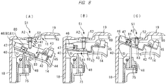
- the solenoid 46 shown in FIG. 8(A) is a specific example 4 of the actuator.
- the same components shown in FIG. 8(A) as the components shown in FIG. 2 are denoted by the same reference symbols as those in FIG. 2 .
- the solenoid 46 is arranged between the plunger 52 and the main body 18 in the direction intersecting the center line A2 in FIG. 8(A) .
- the solenoid 46 urges the plunger 47 leftward in FIG. 8(A) .
- the urging member 80 urges the plunger 47 so as to bring it away from the plunger 52.
- the urging member 80 urges the plunger 47 rightward in FIG. 8(A) .
- the power switch 45 When the operator selects the first mode, applies the operational force to the trigger 14, and brings the push lever 16 away from the workpiece 77, the power switch 45 is turned ON as shown in FIG. 8(B) . The electric current is supplied to the solenoid 46, and the slide member 81 moves from the initial position to the movement position, and then, stops. Further, the push lever switch 93 is turned OFF.
- the transmission member 75 moves to the movement position, and then, stops as shown in FIG. 8(C) .
- the movement force of the transmission member 75 is transmitted to the plunger 52 through the trigger arm 42 and the slide member 81, and the trigger valve 51 is switched from the standby state to the movement state. Therefore, the striking unit 13 shown in FIG. 1 moves from the top dead center to the bottom dead center.
- the solenoid 46 shown in FIG. 8(A) the solenoid 60 or the keep solenoid 61 is provided, if the operator selects the second mode, the action and the control of the driving tool 10 having the solenoid 46 shown in FIG. 2 are the same as those when the operator selects the second mode, except that the movement directions of the plunger 47 and the slide member 81 are reversed.
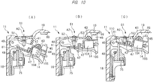
- FIG. 10(A) Another example of a mechanism for operating the slide member 81 is shown in FIG. 10(A) .
- the support shaft 40 shown in FIG. 10(A) is attached to the housing 11.
- the mode selection member 84 shown in FIG. 2 is not provided in FIG. 10(A) .
- components similar to those in FIGs. 2 and 4(A) are denoted by the same reference symbols as those in FIGs. 2 and 4(A) .
- the trigger 14 is attached to the housing 11 through the support shaft 40.
- the mode selection member 84 is not provided.
- a solenoid 104 is attached to the trigger arm 42.
- the solenoid 104 has a coil and a plunger 47.
- An urging member 105 is attached to the plunger 47.
- the urging member 105 urges the plunger 47 in a direction bringing it away from the plunger 52, that is, rightward in FIG. 10(A) .
- the urging member 105 is made of, for example, metal.
- the slide member 81 is fixed to the plunger 47. When the plunger 47 moves, the slide member 81 moves with respect to the trigger arm 42.
- the plunger 47 When the supply of the electric current to the solenoid 104 stops, the plunger 47 is stopped at the initial position farthest from the plunger 52 by the urging force of the urging member 105.
- the plunger 47 moves in a direction bringing it close to the plunger 52 against the urging force of the urging member 105, that is, leftward in FIG. 10(A) , and then, the plunger 47 stops at the movement position.
- the plunger 47 is moved in a direction bringing it away from the plunger 52 by the urging force of the urging member 105, and the plunger 47 stops at the initial position.
- the driving tool 10 having the solenoid 104 can be controlled by the control system in FIG. 3 .
- the control unit 91 turns ON the solenoid switch 95, the electric current is supplied to the solenoid 104.
- the control unit 91 turns OFF the solenoid switch 95, the supply of the electric current to the solenoid 104 stops.
- a state in which the operator releases the operational force from the trigger 14 and the operator brings the push lever 16 away from the workpiece 77 is the initial state of the driving tool 10 shown in FIG. 10(A) .
- the power switch 45 is turned OFF.
- the power of the power supply unit 106 is not supplied to the control unit 91, and the control unit 91 stops.
- the power of the power supply unit 106 is not supplied to the solenoid 104, and the plunger 47 stops at the initial position. Further, the trigger valve 51 stops in the standby state. Therefore, the striking unit 13 stops at the top dead center shown in FIG. 1 .
- the power switch 45 When the operator applies the operational force to the trigger 14 as shown in FIG. 10(B) and stops the trigger 14, the power switch 45 is turned ON.
- the control unit 91 When the power switch 45 is turned ON, the control unit 91 is activated, and the control unit 91 starts the timer.
- the power of the power supply unit 106 is supplied to the solenoid 104, and the plunger 47 moves from the initial position, and stops at the movement position shown in FIG. 10(B) .
- the slide member 81, together with the plunger 47 moves from the initial position to the movement position, and then, stops. An end of the slide member 81 being stopping at the movement position is positioned within the movement range of the transmission member 75.
- the power switch 45 is turned OFF as shown in FIG. 10(C) , the control unit 91 resets the timer, the control unit 91 stops, and the supply of electric current to the solenoid 104 stops.
- the slide member 81 is pressed against the plunger 52.
- the supply of electric current to the solenoid 104 stops, the slide member 81 is stopped at the movement position by the frictional force at the contact point between the slide member 81 and the plunger 52.
- the push lever switch 93 When the operator brings the push lever 16 away from the workpiece 77 while keeping applying the operational force to the trigger 14, the push lever switch 93 is turned OFF.
- the transmission member 75 returns from the movement position to the initial position, and then, stops.
- the trigger valve 51 returns from the movement state to the standby state, and the striking unit 13 returns from the bottom dead center to the top dead center, and then, stops.
- the plunger 47 and the slide member 81 return from the movement position to the initial position, and then, stop. Further, the trigger arm 42 moves counterclockwise, and then, stops, and the power switch 45 is turned ON.
- the control unit 91 When the power switch 45 is turned ON, the control unit 91 is activated, and the timer is started. The electric current is supplied to the solenoid 104. Thus, the plunger 47 and the slide member 81 move from the initial position to the movement position, and then, stop.
- the control unit 91 stops the supply of the electric current to the solenoid 104.
- the plunger 47 moves rightward in FIG. 10(B) , and then, stops at the initial position shown in FIG. 11(A) .
- the entire slide member 81 and the entire trigger arm 42 are positioned outside the movement range of the transmission member 75.
- the driving tool 10 having the solenoid 104 in FIG. 10(A) can perform the control shown in FIG. 7 .
- the transmission member 75 moves.
- the push lever switch 93 is turned ON.
- the movement force of the transmission member 75 is transmitted to the trigger arm 42, and the trigger arm 42 moves clockwise.
- the movement force of the trigger arm 42 is not transmitted to the plunger 52.
- the trigger 14 moves counterclockwise, and then, the trigger 14 stops. Then, the power switch 45 is turned ON, and the control unit 91 is activated.
- the push lever switch 93 is turned ON at the time of the activation of the control unit 91, and therefore, the control unit 91 does not supply the electric current to the solenoid 104.
- the slide member 81 stops at the initial position.
- the trigger arm 42 moves clockwise together with the trigger 14, and the slide member 81 is pressed against the plunger 52. At this time, the trigger arm 42 rotates around the support shaft 43, and the end 110 of the slide member 81 is positioned within the movement range of the transmission member 75. Therefore, the slide member 81 and the transmission member 75 remain in an engaged state.
- the trigger valve 51 is switched from the standby state to the movement state, and the striking unit 13 moves from the top dead center to the bottom dead center. Further, when the operator brings the push lever 16 away from the workpiece 77 and releases the operational force to the trigger 14, the trigger valve 51 is switched from the movement state to the standby state. The trigger 14 returns from the movement state to the initial state, and then, stops.
- FIG. 12(A) Another example of the solenoid and the slide member will be explained with reference to FIG. 12(A) .
- the same components shown in FIG. 12(A) as the components shown in FIGs. 2(A) and 4(A) are denoted by the same reference symbols as those in FIGs. 2(A) and 4(A) .
- the solenoid 60 is attached to the trigger arm 42.
- the slide member 81 has a protrusion 108.
- the driving tool 10 having the mechanism shown in FIG. 12(A) has the control system shown in FIG. 3 .
- the operator operates the mode selection member 84 to stop the mode selection member 84 at the position corresponding to the first mode.
- a state in which the operator releases the operational force from the trigger 14 and brings the push lever 16 away from the workpiece 77 is the initial state of the driving tool 10 in a step S20.
- the protrusion 108 is engaged with the holder 48 to stop the slide member 81.
- the slide member 81 stops against the force of the urging member 80.
- the power switch 45 is turned OFF.
- the control unit 91 stops, and the supply of the power to the solenoid 60 stops.
- the trigger valve 51 stops in the standby state. Therefore, the pressure accumulation chamber 20 and the piston upper chamber 36 are disconnected from each other, and the striking unit 13 stops at the initial position shown in FIG. 1 , that is, at the top dead center. At this time, the protrusion 108 of the slide member 81 often runs on and end 111 of the holder 48. In this case, the slide member 81 is set to the initial position so that the protrusion 108 is positioned on a side of the end 111 shown in FIG. 12(A) .
- the trigger 14 moves counterclockwise in FIG. 12(A) , the power switch 45 is turned ON, and the trigger 14 stops at the movement position.
- the control unit 91 is activated. Since the protrusion 108 is released from the holder 48, the slide member 81 is moved by the force of the urging member 80, and the slide member 81 stops at the initial position shown in FIG. 12(B) .
- the trigger 14 moves clockwise in FIG. 12(B) , and the power switch 45 is turned OFF.
- the slide member 81 moves from the initial position to the movement position against the force of the urging member 80, and the slide member 81 stops at the movement position.
- the control unit 91 releases the operational force from the trigger 14 in the step S22 and supplies the power to the solenoid 60 for a certain period of time from the time of the turning OFF of the power switch 45, and thus, the solenoid 60 maintains the attraction force for a certain period of time.
- a step S23 when the operator applies the operational force to the trigger 14, the protrusion 81 is released from the holder 48.
- the solenoid 60 keeps the slide member 81 to be at the movement position.
- the power switch 45 is turned ON as shown in FIG. 12(C) .
- the control unit 91 is activated, and the control unit 91 starts the timer in the step S23.
- a step S24 the control unit 91 determines whether the push lever switch 93 is turned ON within a predetermined time from the start of the timer.
- the control unit 91 determines "Yes" in the step S24, the control unit 91 resets the timer in a step S25.
- the movement force of the push lever 16 is transmitted through the transmission member 75 to the trigger arm 42.
- the trigger arm 42 moves clockwise in FIG. 12(C) , and the power switch 45 is turned OFF in the step S25.
- the control unit 91 stops.
- the push lever switch 93 When the operator brings the push lever 16 away from the workpiece 77 while keeping the state of the application of the operational force to the trigger 14, the push lever switch 93 is turned OFF in a step S26.
- the transmission member 75 returns from the movement position to the initial position, and then, stops.
- the trigger arm 42 moves counterclockwise and stops at the initial position, and the power switch 45 is turned ON in the step S26.
- the control unit 91 is activated.
- the control unit 91 starts the timer in the step S26, and the procedure proceeds to the step S24.
- control unit 91 determines "No" in the step S24, the control unit stops the supply of the power to the solenoid 60 in a step S27. In this manner, the slide member 81 is moved from the movement position shown in FIG. 12(C) by the force of the urging member 80, and the slide member 81 stops at the initial position shown in FIG. 12(B) .
- the trigger valve 51 remains in the standby state, and the striking unit 13 stops at the top dead center. Therefore, the fastener 73 can be prevented from being driven into the foreign matter.
- the control unit 91 determines whether the power switch 45 is turned OFF in a step S28 following the step S27. If the control unit 91 determines "No" in the step S28, the control unit 91 repeats the determination in the step S28. When the control unit 91 determines "Yes" in the step S28, the procedure proceeds to the step S23.
- the driving tool 10 when the operator operates the mode selection member 84 to select the second mode, the driving tool 10 becomes in the following state.
- the trigger 14 and the trigger arm 42 stop at a position farthest away from the main body 18 in the direction intersecting the center line A2.
- the protrusion 108 is away from the holder 48.
- the power switch 45 is turned OFF, and no power is supplied to the solenoid 46.
- the slide member 81 is urged by the urging force of the urging member 80, and the slide member 81 stops at the initial position.
- the trigger valve 51 stops in the standby state, and the compressed air in the pressure accumulation chamber 20 is not supplied to the piston upper chamber 36.
- the striking unit 13 stops at the initial position, that is, at the top dead center.
- the trigger 14 moves counterclockwise. In this manner, although the trigger 14 reaches the movement position, and then, stops, the power switch 45 remains turned OFF.
- the trigger arm 42 moves counterclockwise, and the contact portion 83 of the slide member 81 is pressed against the plunger 52.
- the trigger valve 51 is switched from the standby state to the movement state, and the striking unit 13 moves from the top dead center to the bottom dead center.
- the trigger valve 51 is switched from the movement state to the standby state.
- the trigger 14 returns from the movement state to the initial state, and then, stops.
- the trigger 14 moves counterclockwise, and then, stops at the movement position.
- the power switch 45 remains turned OFF.
- the entire trigger arm 42 stops outside the movement range of the transmission member 75.
- the slide member 81 always stops at the initial position.
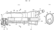
- FIGs. 15(A) and 15(B) show another example of the power supply unit 106.
- a holding hole 100 is provided in the end cover 22, and the power supply unit 106 is provided inside the handle 19, that is, the pressure accumulation chamber 20.
- the power supply unit 106 has an enclosure 101 and a battery cell 87.
- the enclosure 101 has a cylindrical shape, and the enclosure 101 is arranged in both the holding hole 100 and the pressure accumulation chamber 20.
- a cap 102 closes an opening of the enclosure g 101. A part of the cap 102 is arranged in the outside B1.
- the battery cell 87 and the control unit 91 are arranged inside the enclosure 101.
- the battery cell 87 has a cylindrical shape, and a plurality of battery cells 87 are concentrically arranged.
- a spring 103 is arranged between the cap 102 and one of the battery cells 87.
- the spring 103 electrically connects a terminal of the battery cell 87 and a terminal of the battery cell 87. The operator can detach the cap 102 from the enclosure 101, and insert/remove the battery cell 87 into/from the enclosure 101.
- the trigger 14 is an example of an operation member
- the push lever 16 is an example of a contact member.
- Each of the trigger arm 42 and the slide member 81 is an example of a transmission mechanism.
- Each of the solenoids 46, 60 and 104 is an example of an actuator, and the plunger 47 is an example of a movable member.
- the trigger valve 51 is an example of a driving unit and a valve.
- the plunger 52 is an example of a switching member.
- the keep solenoid 61 is an example of an actuator.
- the passage 110 is an example of a path. The state in which the slide member 81 is pressed against the plunger 52 is a transmission state.
- the state in which the slide member 81 is away from the plunger 52 or the state in which the plunger 52 enters the notch 82 is a disconnection state.
- the notch 82 is a non-contact portion.
- the piston upper chamber 36 is an example of a pressure chamber.
- the driving tool is not limited to the above-described embodiments, and can be variously changed within the scope of the invention.
- the power switch may be switched ON and OFF by an operation of a mode switching member.
- the power switch is turned ON when the first mode is selected and turned OFF when the second mode is selected.
- the power supply unit and the control unit may be provided in the magazine.
- the actuator provided in the operation member may be a pneumatic cylinder instead of the solenoid.
- the pneumatic cylinder is moved by the compressible gas of the pressure accumulation chamber.
Landscapes
- Physics & Mathematics (AREA)
- Fluid Mechanics (AREA)
- Engineering & Computer Science (AREA)
- Mechanical Engineering (AREA)
- Portable Nailing Machines And Staplers (AREA)
Abstract
Description
- The present invention relates to a driving tool including a striking unit which moves in a predetermined direction and strikes a fastener, and a driving unit which moves the striking unit.
- A driving tool including a striking unit and a driving unit is described in Patent Document 1. The driving tool described in the Patent Document 1 includes a housing, a pressure accumulation chamber, a pressure chamber, a striking unit, a push lever, a cylinder, a trigger, a trigger valve, and a delay valve as an actuator. The pressure accumulation chamber is provided in the housing, and compressed air is supplied to the pressure accumulation chamber.
- When an operator uses the driving tool described in the Patent Document 1, the delay valve connects a path for use in supplying the compressed gas of the pressure accumulation chamber to the pressure chamber during a predetermined time from application of an operational force to the trigger by the operator. Thus, when the operational force is applied to the push lever within the predetermined time from the application of the operational force to the trigger, the compressed air is supplied to the pressure chamber, and the striking unit moves in the direction of striking a fastener.
- On the other hand, after the predetermined time has elapsed from the application of the operational force to the trigger, the delay valve disconnects the path for use in supplying the compressed gas from the pressure accumulation chamber to the pressure accumulation chamber. Thus, even if the operational force is applied to the push lever after the predetermined time has elapsed from the application of the operational force to the trigger, the compressed air is not supplied to the pressure chamber. In other words, the striking unit does not move in the direction of striking the fastener.
- Patent Document 1: International Patent Publication No.
WO2017-115593 - The inventors of the present application have found that it is necessary to secure an arrangement space dedicated to an actuator.
- An objective of the present invention is to provide a driving tool which can eliminate the need for securing the arrangement space dedicated to the actuator.
- A driving tool of one embodiment includes: a striking unit configured to be movable to strike a fastener; a housing configured to support the striking unit; an operation member provided in the housing and configured to be moved by an operational force of an operator; a contact member provided in the housing and configured to be movable in contact with a workpiece into which the fastener is driven; and a driving unit configured to have a standby state in which the striking unit is stopped and a movement state in which the striking unit is moved, and configured to be switched between the standby state and the movement state when a switching member moves, and the driving tool further includes: a transmission mechanism operably provided in the operation member and configured to have a transmission state in which a movement force of the operation member and a movement force of the contact member can be transmitted to the switching member and a disconnection state in which the movement force of the operation member and the movement force of the contact member cannot be transmitted to the switching member; and an actuator provided in the operation member and configured to switch the transmission mechanism between the transmission state and the disconnection state.
- According to the driving tool of one embodiment, the need for securing the dedicated arrangement space for use in arranging the actuator can be eliminated.
-
-
FIG. 1 is a front cross-sectional view showing the overall structure of a driving tool according to an embodiment of the present invention; -
FIG. 2(A) is a cross-sectional view showing a trigger and a slide member provided in the driving tool, andFIG. 2(B) is a side cross-sectional view taken along a line II-II inFIG. 2A ; -
FIG. 3 is a block diagram showing a control unit system of the driving tool inFIG. 1 ; -
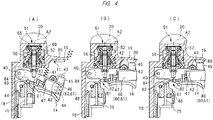
FIGs. 4(A), 4(B), and 4(C) are cross-sectional views each showing the operation of the trigger; -
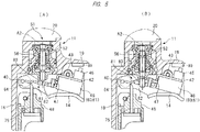
FIGs. 5(A) and 5(B) are cross-sectional views each showing the operation of the trigger; -
FIGs. 6(A) and 6(B) are cross-sectional views each showing the operation of the trigger corresponding to a second mode; -
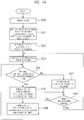
FIG. 7 is a flowchart including an example of control performed by the driving tool; -
FIGs. 8(A), 8(B) and 8(C) are cross-sectional views each showing the operation of the trigger; -
FIGs. 9(A) and 9(B) are cross-sectional views each showing the operation of the trigger; -
FIGs. 10(A), 10(B) and 10(C) are cross-sectional views each showing the operation of the trigger; -
FIGs. 11(A) and 11(B) are cross-sectional views each showing the operation of the trigger; -
FIGs. 12(A), 12(B) and 12(C) are cross-sectional views each showing the operation of the trigger; -
FIGs. 13(A) and 13(B) are cross-sectional views each showing the operation of the trigger; -
FIG. 14 is a flowchart including another example of control performed by the driving tool; and -
FIG. 15(A) is a longitudinal cross-sectional view showing another example of a power supply unit provided in the driving tool, andFIG. 15(B) is a side cross-sectional view taken along a line III-III inFIG. 15(A) . - Next, some driving tools included in embodiments of the present invention will be explained with reference to the drawings.
- A
driving tool 10 shown inFIGs. 1 and2 includes ahousing 11, acylinder 12, astriking unit 13, atrigger 14, aninjection unit 15, and apush lever 16. Amagazine 17 is also attached to thedriving tool 10. Thehousing 11 has a cylindricalmain body 18, ahead cover 21 fixed to themain body 18, and ahandle 19 connected to themain body 18. - A
pressure accumulation chamber 20 is formed over the inside of thehandle 19, the inside of themain body 18 and the inside of thehead cover 21. Anend cover 22 is fixed to an end of thehandle 19 opposite to themain body 18. Aplug 23 is attached to theend cover 22. An air hose is connected to theplug 23. Compressed air as a compressible gas is supplied to thepressure accumulation chamber 20 through the air hose. Thecylinder 12 is provided inside themain body 18. Thehead cover 21 has anexhaust passage 24. Theexhaust passage 24 communicates with the outside B1 of thehousing 11. - A
head valve 31 is provided inside thehead cover 21. Thehead valve 31 is movable in a direction of a center line A1 of thecylinder 12. Acontrol chamber 27 is formed inside thehead cover 21. Anurging member 28 is provided in thecontrol chamber 27. Theurging member 28 is, for example, a compression coil spring made of metal. Theurging member 28 urges, in the direction of the center line A1, thehead valve 31 in a direction bringing it close to thecylinder 12. Astopper 29 is provided inside thehead cover 21. To thecylinder 12, avalve seat 32 is attached at an end of a position closest to thehead valve 31 in the direction of the center line A1. - The
striking unit 13 has apiston 34 and adriver blade 35 fixed to thepiston 34. Thepiston 34 is arranged inside thecylinder 12. Thestriking unit 13 can move in the direction of the center line A1, and then, stop. A seal member 30 is attached to an outer peripheral surface of thepiston 34. A pistonupper chamber 36 is formed between thestopper 29 and thepiston 34. Apassage 110 is formed between thehead valve 31 and thevalve seat 32. - When the
head valve 31 is separated from thevalve seat 32, thepassage 110 is open, and thepressure accumulation chamber 20 is connected to the pistonupper chamber 36. When thehead valve 31 is pressed against thevalve seat 32, thepassage 110 is closed, and thepressure accumulation chamber 20 is disconnected from the pistonupper chamber 36. The pistonupper chamber 36 communicates with the outside B1 of thehousing 11 through theexhaust passage 24. - The
injection unit 15 is fixed to an end portion of themain body 18 opposite to a portion having thehead cover 21 in the direction of the center line A1. Theinjection unit 15 has aninjection path 72. The center line A1 is positioned inside theinjection path 72, and thedriver blade 35 is movable inside theinjection path 72 in the direction of the center line A1. - A
bumper 37 is provided inside thecylinder 12. Thebumper 37 is arranged inside thecylinder 12 at a position closest to theinjection unit 15 in the direction of the center line A1. Thebumper 37 has ashaft hole 38, and thedriver blade 35 is movable inside theshaft hole 38 in the direction of the center line A1. Inside thecylinder 12, a piston lower chamber 39 is formed between thepiston 34 and thebumper 37. - A
trigger valve 51 is provided at a connection point between themain body 18 and thehandle 19. Thetrigger valve 51 has aplunger 52, avalve body 55,passages member 69. Theplunger 52 can move in a direction of a center line A2, and then, stop. The center line A1 is parallel to the center line A2. Thepassage 56 is connected to thecontrol chamber 27 through apassage 57. Thepassage 90 communicates with the outside B1 of thehousing 11. The urgingmember 69 is, for example, a compression spring, and the urgingmember 69 urges theplunger 52 in a direction bringing it away from thepressure accumulation chamber 20 in the direction of the center line A2. - The
magazine 17 is supported by theinjection unit 15 and thehandle 19. Themagazine 17 houses afastener 73. Themagazine 17 has afeeder 74, and thefeeder 74 feeds thefastener 73 inside themagazine 17 to aninjection path 72. - As shown in
FIG. 1 , thepush lever 16 is attached to theinjection unit 15. Thepush lever 16 is operable with respect to theinjection unit 15 and thehousing 11 in the direction of the center line A1. As shown inFIG. 2 , aholder 48 is provided in themain body 18, and atransmission member 75 is supported by theholder 48. Thetransmission member 75 is movable in the direction of the center line A2. An urgingmember 76 is provided between theholder 48 and thetransmission member 75. The urgingmember 76 is, for example, a metal spring. The urgingmember 76 urges thetransmission member 75 in a direction bringing it away from thetrigger valve 51 in the direction of the center line A2. - As shown in
FIG. 4(A) , amode selection member 84 is attached to thehousing 11. Themode selection member 84 is movable within a predetermined angle range with respect to thehousing 11. An operator operates themode selection member 84 to rotate and stop the mode selection member. Themode selection member 84 is, for example, a lever or a knob. The operator selects either a first mode or a second mode as a mode for using thedriving tool 10. Before using thedriving tool 10, the operator stops themode selection member 84 at a position corresponding to the first mode or a position corresponding to the second mode. - The first mode is a mode making the
striking unit 13 move in a procedure in which the operator presses thepush lever 16 against aworkpiece 77 while the operator applies an operational force to thetrigger 14. The second mode is a mode making thestriking unit 13 move in a procedure in which the operator applies the operational force to thetrigger 14 while the operator presses thepush lever 16 against theworkpiece 77. - The
trigger 14 is attached to themode selection member 84 through asupport shaft 40. Thesupport shaft 40 is arranged at a position eccentric from a rotation center of themode selection member 84. When the operator rotates themode selection member 84, thesupport shaft 40 moves in a direction intersecting the center line A2. Thetrigger 14 is also rotatable around thesupport shaft 40 within a predetermined angle range. An urgingmember 41 is provided, and the urgingmember 41 urges thetrigger 14 clockwise inFIG. 4(A) . The urgingmember 41 is, for example, a metal spring. - A
trigger arm 42 is attached to thetrigger 14 through asupport shaft 43. Thetrigger arm 42 is movable around thesupport shaft 43 within a predetermined angle range with respect to thetrigger 14. Thetrigger 14 is provided with an urgingmember 44. The urgingmember 44 urges thetrigger arm 42 counterclockwise with respect to thetrigger 14. The urgingmember 44 is, for example, a metal spring. A part of thetrigger 14 and a part of thetrigger arm 42 are arranged between thetrigger valve 51 and theholder 48 in the direction of the center line A2. Apower switch 45 shown inFIG. 3 is attached to thetrigger arm 42. - A
solenoid 46 is attached to thetrigger arm 42. Thesolenoid 46 shown inFIG. 4(A) is a specific example 1 of an actuator. Theplunger 52 is arranged between thesolenoid 46 and themain body 18 in a direction intersecting the center line A2. Thesolenoid 46 has a coil and aplunger 47. Theplunger 47 can be brought close to and away from theplunger 52. Theplunger 47 is made of a magnetic material such as iron. When electric current flows through the coil of thesolenoid 46, the coil generates magnetic attraction force. The coil urges theplunger 47 in a direction bringing it away from theplunger 52 by the magnetic attraction force. The coil urges theplunger 47 rightward inFIG. 4(A) . - An urging
member 80 is provided on an outer periphery of theplunger 47. The urgingmember 80 urges theplunger 47 in the direction bringing it close to theplunger 52. The urgingmember 80 urges theplunger 47 leftward inFIG. 4(A) . The urgingmember 80 is, for example, a metal spring. Assumed is that a movement force acting on theplunger 47 by the magnetic attraction force of the coil is larger than a movement force applied from the urgingmember 80 to theplunger 47. - The
slide member 81 is fixed to theplunger 47. Theslide member 81 has acontact portion 83 and anotch 82. Theslide member 81 is guided by thetrigger arm 42, and moves or stops together with theplunger 47. Thesolenoid 46 and theslide member 81 are arranged inside an arrangement region of thetrigger 14 in a plane perpendicular to thesupport shaft 40. - As shown in
FIGs. 1 ,2(A), and 2(B) , thepower supply unit 106 is attached to thehousing 11, for example, to thehandle 19. Aconcave portion 85 is provided on an outer surface of thehandle 19 between thetrigger valve 51 and theend cover 22. Theconcave portion 85 is provided in a portion of thehandle 19 close to themagazine 17 in the direction of the center line A2. Thepower supply unit 106 is arranged in theconcave portion 85. - The
power supply unit 106 has anenclosure 86 and abattery cell 87. Theenclosure 86 is made of an insulating material such as a synthetic resin. Theenclosure 86 can come in and out of theconcave portion 85. Thebattery cell 87 is housed in theenclosure 86. Thebattery cell 87 has a cylindrical shape, and a plurality ofbattery cells 87 are arranged in a radial direction. Thebattery cell 87 is a chargeable/dischargeable secondary battery. As thebattery cell 87, any one of a lithium-ion battery, a nickel hydrogen battery, a lithium-ion polymer battery, and a nickel cadmium battery can be used. The battery cell may be a primary battery. Further, thepower supply unit 106 has apower cable 109 for supplying power to thesolenoid 46. - A
grip 88 covers outer surfaces of thehandle 19 and thepower supply unit 106. Thegrip 88 is made of, for example, a synthetic rubber, and has a cylindrical shape. When thegrip 88 covers the outer surfaces of thehandle 19 and thepower supply unit 106, thepower supply unit 106 does not fall off from theconcave portion 85. When the operator detaches thegrip 88 from thehandle 19, thepower supply unit 106 can come in and out of theconcave portion 85. - A
protrusion 89 is provided on an outer surface of theenclosure 86. When thepower switch 45 contacts theprotrusion 89, thepower switch 45 is turned ON. When thepower switch 45 is away from theprotrusion 89, thepower switch 45 is turned OFF. -
FIG. 3 is a block diagram showing a control system of the drivingtool 10. Acontrol unit 91 and a terminal 107 are provided inside theenclosure 86. Theterminals 107 are electrically connected to the plurality ofbattery cells 87, respectively. Thecontrol unit 91 is a microcomputer having an input interface, an output interface, an arithmetic processing unit, a memory, and a timer. Anelectric circuit 92 is provided between thecontrol unit 91 and thepower supply unit 106. - The turning ON of the
power switch 45 is to connect theelectric circuit 92. The turning OFF of thepower switch 45 is to disconnect theelectric circuit 92. When thepower switch 45 is turned ON, the power of thepower supply unit 106 is supplied to thecontrol unit 91, and thecontrol unit 91 is activated. When thepower switch 45 is turned OFF, the power of thepower supply unit 106 is not supplied to thecontrol unit 91, and thecontrol unit 91 stops. Apush lever switch 93 is provided in theinjection unit 15. - When the operator presses the
push lever 16 against theworkpiece 77, thetransmission member 75 which is provided on thepush lever 16 is brought close to thetrigger valve 51. When the operator brings thepush lever 16 away from theworkpiece 77, thetransmission member 75 is brought away from thetrigger valve 51. Anelectric circuit 94 is provided between thepower supply unit 106 and thesolenoid 46. Asolenoid switch 95 for connecting and disconnecting theelectric circuit 94 is provided. - The
control unit 91 turns ON and OFF thesolenoid switch 95. The turning ON of thesolenoid switch 95 is to connect theelectric circuit 94. The turning OFF of thesolenoid switch 95 is to disconnect theelectric circuit 94. Avoltage detection sensor 62 for detecting a voltage of thepower supply unit 106 is provided. A signal from thevoltage detection sensor 62 is input to thecontrol unit 91. - Next, a usage example of the driving
tool 10 will be explained with reference to the flowchart inFIG. 7 . - When the operator operates the
mode selection member 84 to stop themode selection member 84 at the position corresponding to the first mode, thetrigger 14 is closest to themain body 18 in the direction intersecting the center line A2 as shown inFIG. 4(A) . Thetrigger arm 42 is closest to thesupport shaft 40 in the direction intersecting the center line A2. - A state in which the operator releases the operational force from the
trigger 14 and brings thepush lever 16 away from theworkpiece 77 is an initial state of the drivingtool 10 in a step S10 inFIG. 7 . Thetrigger 14 is brought into contact with theholder 48, and thetrigger 14 and thetrigger arm 42 stop at their respective initial positions. Thepush lever 16 also stops at the initial position, and thepush lever switch 93 is turned OFF. When thetrigger 14 stops at the initial position, thepower switch 45 is turned OFF. Thus, the power of thepower supply unit 106 is not supplied to thecontrol unit 91, and thecontrol unit 91 stops. - The
solenoid switch 95 is turned OFF, and the power of thepower supply unit 106 is not supplied to thesolenoid 46. Therefore, theplunger 47 stops at the initial position, and theslide member 81 stops at the initial position. The initial position of theplunger 47 is a position closest to theplunger 52. The initial position of theslide member 81 is a position at which theslide member 81 is closest to thetransmission member 75 in the moving direction of theslide member 81. In other words, theplunger 47 stops at the position closest to thetransmission member 75 by the force of the urgingmember 80. - The
trigger valve 51 stops in a standby state. In the standby state of thetrigger valve 51, thepressure accumulation chamber 20 and thepassage 56 are connected to each other, and the compressed air is supplied to thecontrol chamber 27. Thus, thehead valve 31 is pressed against thevalve seat 32. Therefore, thepressure accumulation chamber 20 and the pistonupper chamber 36 are disconnected from each other, and thestriking unit 13 stops at the initial position shown inFIG. 1 , that is, at the top dead center. - When the operator applies the operational force to the
trigger 14, thetrigger 14 moves counterclockwise inFIG. 4(A) , and thepower switch 45 is turned ON as inFIG. 4(B) , and thetrigger 14 stops at a movement position. In a step S11, when thepower switch 45 is turned ON, the power of thepower supply unit 106 is supplied to thecontrol unit 91, and thecontrol unit 91 is activated. Thecontrol unit 91 starts the timer, and turns ON thesolenoid switch 95. The power of thepower supply unit 106 is supplied through thepower cable 109 to thesolenoid 46, and the coil generates the magnetic attraction force. - The
slide member 81 moves from the initial position shown inFIG. 4(B) to the movement position shown inFIG. 4(C) , and then, stops. The movement position of theslide member 81 is at position at which theslide member 81 is farthest away from thetransmission member 75 in the moving direction of theslide member 81. - In a step S13, the
control unit 91 determines whether thepush lever switch 93 has been turned ON within a predetermined time from the start of the timer. The predetermined time is, for example, three seconds. If thecontrol unit 91 determines "Yes" in the step S13, thecontrol unit 91 resets the timer in a step S14, and turns OFF thesolenoid switch 95. Thus, the power of thepower supply unit 106 is not supplied to thesolenoid 46. - A movement force of the
push lever 16 is transmitted to thetrigger arm 42 through thetransmission member 75. Thetrigger arm 42 moves clockwise around thesupport shaft 43 inFIG. 4(A) , and thepower switch 45 is turned OFF as shown inFIG. 5(A) . When thepower switch 45 is turned OFF in the step S14, the power of thepower supply unit 106 is not supplied to thecontrol unit 91, and thecontrol unit 91 stops. - Further, when the
trigger arm 42 moves clockwise, thecontact portion 83 of theslide member 81 is pressed against theplunger 52 of thetrigger valve 51 as shown inFIG. 5(A) . In this manner, thetrigger valve 51 is switched from the standby state to the movement state. When thetrigger valve 51 is in the movement state, thepressure accumulation chamber 20 and thepassage 56 are disconnected from each other, and thepassage 56 and thepassage 90 are connected to each other. Thus, the compressible gas in thecontrol chamber 27 is discharged to the outside B1 through thepassage 90. Thehead valve 31 is brought away from thevalve seat 32, and thepressure accumulation chamber 20 communicates with the pistonupper chamber 36. As a result, the compressible gas in thepressure accumulation chamber 20 is supplied to the pistonupper chamber 36, the strikingunit 13 moves from the top dead center to the bottom dead center, and thedriver blade 35 strikes thefastener 73. Thefastener 73 is driven into theworkpiece 77 in the step S14. - Further, when the operator presses the
push lever 16 against theworkpiece 77, thetransmission member 75 is pressed against theplunger 52 as shown inFIG. 5(A) . Thus, in a state in which the power of thepower supply unit 106 is not supplied to thesolenoid 46, theslide member 81 is stopped at the movement position by a frictional force at the contact point between theslide member 81 and theplunger 52. - When the operator keeps the state of the application of the operational force on the
trigger 14 and brings thepush lever 16 away from theworkpiece 77, thepush lever switch 93 is turned OFF in a step S15. Further, thetransmission member 75 returns from the movement position to the initial position, and then, stops. Thetrigger arm 42 is moved counterclockwise by the force of the urgingmember 44, and then, stops, and thepower switch 45 is turned ON in the step S15. - In the step S15, when the
power switch 45 is turned ON, the power of thepower supply unit 106 is supplied to thecontrol unit 91, and thecontrol unit 91 is activated. Further, thecontrol unit 91 starts the timer in the step S15 and turns ON thesolenoid switch 95. Thus, the power of thepower supply unit 106 is supplied to thesolenoid 46, and theslide member 81 moves from the initial position to the movement position, and then, stops. Thetrigger valve 51 returns from the movement state to the standby state in the step S15. A procedure for thecontrol unit 91 proceeds to the step S15 followed by the step S12. - On the other hand, if the
control unit 91 determines "No" in the step S13, thesolenoid switch 95 is turned OFF and the timer is reset in a step S16. Thus, the power of thepower supply unit 106 is not supplied to thesolenoid 46, and thesolenoid 46 returns to the initial position, and then, stops. In other words, theplunger 47 is moved by the force of the urgingmember 80, and theplunger 47 stops at the position closest to thetransmission member 75. Theslide member 81, together with theplunger 47, returns from the movement position shown inFIG. 4(C) to the initial position shown inFIG. 4(B) , and then, stops. - Here, when the
push lever 16 is brought into contact with a foreign matter other than theworkpiece 77 to move thetransmission member 75 so that thetrigger arm 42 moves clockwise inFIG. 4(B) , theplunger 52 enters thenotch 82 as shown inFIG. 5 (B) . Thus, the movement force of thetrigger arm 42 is not transmitted to thetrigger valve 51, and thetrigger valve 51 remains in the standby state. - As described above, even if the
push lever 16 is brought into contact with the foreign matter after a predetermined time from the application of the operational force to thetrigger 14, thetrigger valve 51 is maintained in the standby state, and thestriking unit 13 stops at the top dead center. Therefore, thefastener 73 can be prevented from being driven into the foreign matter. - The
control unit 91 determines whether thepower switch 45 is turned OFF in a step S17 following the step S16. Thecontrol unit 91 repeats the determination in the step S17 if the control unit determines "No" in the step S17. When thecontrol unit 91 determines "Yes" in the step S17, the procedure for the control unit proceeds to the step S10. - In the
driving tool 10 of the present embodiment, to theplunger 52 of thetrigger valve 51, theslide member 81 transmits the movement force transmitted from thepush lever 16 to thetrigger arm 42. Thesolenoid 46 making theslide member 81 move and stop is provided on thetrigger 14. Therefore, it is unnecessary to provide an exclusive-use space for arranging thesolenoid 46. - In order to move and stop the
slide member 81, asolenoid 60 is provided in place of thesolenoid 46. Thesolenoid 60 is a specific example 2 of the actuator, and thesolenoid 60 has a coil and aplunger 47. The supply of electric current to the solenoid generates an attraction force, but cannot move theplunger 47 and theslide member 81 so as to be against the force of the urgingmember 80. In other words, thesolenoid 60 is an electromagnet. Theplunger 52 is arranged between thesolenoid 60 and themain body 18 in the direction intersecting the center line A2. - Since the
solenoid 60 is provided, theplunger 47 and theslide member 81 stop at the initial position even if the power is supplied to thesolenoid 60 in the step S11 inFIG. 7 . In the step S12, the operator manually moves theplunger 47 and theslide member 81 from the initial position to the movement position. In this manner, thesolenoid 60 keeps theplunger 47 and theslide member 81 at the movement position. - Further, even if the power is supplied to the
solenoid 60 in the step S15, theplunger 47 and theslide member 81 stop at the initial position. In the step S15, the operator manually moves theplunger 47 and theslide member 81 from the initial position to the movement position. In this manner, thesolenoid 60 holds theplunger 47 and theslide member 81 at the movement position, and the procedure proceeds to the step S12. Other controls in the case of the usage of thesolenoid 60 are the same as other controls corresponding to the flowchart inFIG. 7 . - In order to move and stop the
slide member 81, a keep solenoid 61 is provided in place of thesolenoid 46. The keep solenoid 61 is a specific example 3 of the actuator, and the keep solenoid 61 has a coil and a permanent magnet. In this case, the urgingmember 80 is not provided. Thesolenoid switch 95 can be turned ON and OFF, and the direction of the electric current supplied to the keep solenoid 61 can be switched. When power is supplied from thepower supply unit 106 to the keep solenoid 61, theplunger 47 is moved. - When the direction of the electric current supplied to the keep solenoid 61 is switched, a direction of the movement of the
plunger 47 is switched. When the supply of the power from thepower supply unit 106 to the keep solenoid 61 stops, theplunger 47 is stopped at the initial position or the movement position by an attraction force of the permanent magnet. Theplunger 52 is arranged between the keep solenoid 61 and themain body 18 in a direction intersecting with the center line A2. - An example of control in a case of usage of the keep solenoid 61 will be explained with reference to the flowchart in
FIG. 7 . In the step S10, no power is supplied to the keep solenoid 61, and theplunger 47 stops at the initial position. In the step S11, thecontrol unit 91 turns ON thesolenoid switch 95 to supply the power to the keep solenoid 61. A direction of the electric current supplied to the keep solenoid 61 is the direction in which theslide member 81 moves from the initial position to the movement position in the step S12. In the step S12, thecontrol unit 91 stops the supply of the power to the keep solenoid 61, and theslide member 81 stops at the movement position. - When the
control unit 91 determines "Yes" in the step S13, the procedure proceeds through the step S14 to the step S15, and the power is supplied to the keep solenoid 61. Thus, theslide member 81 returns from the movement position to the initial position. The procedure in thecontrol unit 91 proceeds from the step S15 to the step S12, and the power is supplied to the keep solenoid 61 and stops. Thus, theslide member 81 moves from the initial position to the movement position, and then, stops at the movement position. - If the
control unit 91 determines "No" in the step S13, thecontrol unit 91 supplies and stops the power to the keep solenoid 61 in the step S16. Thus, theslide member 81 moves from the movement position to the initial position, and then, stops at the initial position. Other controls in the case of the usage of the keep solenoid 61 are the same as other controls corresponding to the flowchart inFIG. 7 . - First, an example with the
solenoid 46 will be explained. When the operator stops themode selection member 84 at a position corresponding to the second mode, thetrigger 14 and thetrigger arm 42 stop at a position farthest away from themain body 18 in the direction intersecting the center line A2 as shown inFIG. 6(A) . In an initial state in which the operator releases the operational force from thetrigger 14 and brings thepush lever 16 away from theworkpiece 77, thepower switch 45 is turned OFF and thesolenoid switch 95 is turned OFF. The power is not supplied to thesolenoid 46, and theslide member 81 stops at the initial position. Further, thetrigger valve 51 stops in the standby state, and the compressed air in thepressure accumulation chamber 20 is not supplied to the pistonupper chamber 36. Thus, the strikingunit 13 stops at the initial position, that is, at the top dead center. - When the operator presses the
push lever 16 against theworkpiece 77 without applying the operational force to thetrigger 14, thetransmission member 75 moves. The movement force of thetransmission member 75 is not transmitted to theplunger 52. When the operator applies the operational force to thetrigger 14 while pressing thepush lever 16 against theworkpiece 77, thetrigger 14 moves counterclockwise inFIG. 6(A) . In this manner, although thetrigger 14 reaches and then stops at the movement position, thepower switch 45 remains turned OFF. - Further, the
trigger arm 42 moves counterclockwise, and thecontact portion 83 of theslide member 81 is pressed against theplunger 52 as shown inFIG. 6(B) . Thus, thetrigger valve 51 is switched from the standby state to the movement state, and thestriking unit 13 moves from the top dead center to the bottom dead center. Further, when the operator brings thepush lever 16 away from theworkpiece 77 and releases the operational force from thetrigger 14, thetrigger valve 51 is switched from the movement state to the standby state. Thetrigger 14 returns from the movement state to the initial state shown inFIG. 6(A) , and then, stops. - When the operator selects the second mode and when the operator applies the operational force to the
trigger 14 while brings thepush lever 16 away from theworkpiece 77, thetrigger 14 moves counterclockwise, and then, stops at the movement position. However, thepower switch 45 remains turned OFF. Further, theentire trigger arms 42 stop outside the movement range of thetransmission member 75. Thus, even if the operator presses thepush lever 16 against theworkpiece 77 while applying the operational force to thetrigger 14, the movement force of thetransmission member 75 is not transmitted to thetrigger arm 42. In other words, thetrigger valve 51 remains in the standby state, and thestriking unit 13 stops at the top dead center. - Even when the
solenoid 60 is provided in place of thesolenoid 46, the power of thepower supply unit 106 is not supplied to thesolenoid 60, and theslide member 81 stops at the initial position. Further, even when the keep solenoid 61 is provided in place of thesolenoid 46, the power of thepower supply unit 106 is not supplied to the keep solenoid 61, and theslide member 81 stops at the initial position. - The
solenoid 46 shown inFIG. 8(A) is a specific example 4 of the actuator. The same components shown inFIG. 8(A) as the components shown inFIG. 2 are denoted by the same reference symbols as those inFIG. 2 . Thesolenoid 46 is arranged between theplunger 52 and themain body 18 in the direction intersecting the center line A2 inFIG. 8(A) . When an electric current is supplied to the coil of thesolenoid 46, theplunger 47 is brought close to theplunger 52. In other words, thesolenoid 46 urges theplunger 47 leftward inFIG. 8(A) . The urgingmember 80 urges theplunger 47 so as to bring it away from theplunger 52. In other words, the urgingmember 80 urges theplunger 47 rightward inFIG. 8(A) . - When the operator selects the first mode and releases the operational force to the
trigger 14 and thepush lever 16 shown inFIG. 1 is separated from theworkpiece 77, thetrigger 14, thetrigger arm 42 and thetrigger valve 51 are in the initial state shown inFIG. 8(A) . In other words, thepower switch 45 is turned OFF, and thepush lever switch 93 is turned OFF. - When the operator selects the first mode, applies the operational force to the
trigger 14, and brings thepush lever 16 away from theworkpiece 77, thepower switch 45 is turned ON as shown inFIG. 8(B) . The electric current is supplied to thesolenoid 46, and theslide member 81 moves from the initial position to the movement position, and then, stops. Further, thepush lever switch 93 is turned OFF. - When the
push lever 16 is pressed against theworkpiece 77 within a predetermined time from the operator's selection for the first mode and the application of the operational force to thetrigger 14, thetransmission member 75 moves to the movement position, and then, stops as shown inFIG. 8(C) . The movement force of thetransmission member 75 is transmitted to theplunger 52 through thetrigger arm 42 and theslide member 81, and thetrigger valve 51 is switched from the standby state to the movement state. Therefore, the strikingunit 13 shown inFIG. 1 moves from the top dead center to the bottom dead center. - On the other hand, after the predetermined time in the state of the
push lever 16 away from theworkpiece 77 has elapsed from the operator's selection for the first mode and the application of the operational force to thetrigger 14, the supply of the electric current to thesolenoid 46 stops, and theslide member 81 moves from the movement position to the initial position shown inFIG. 9(A) , and then, stops at the initial position. - Thus, after the predetermined time in the state of the
push lever 16 away from theworkpiece 77 has elapsed from the operator's selection for the first mode and the application of the operational force to thetrigger 14, if thepush lever 16 is brought into contact with the foreign matter while thetransmission member 75 moves, theplunger 52 enters thenotch 82 of theslide member 81 as shown inFIG. 9(B) . Thus, thetrigger valve 51 remains in the standby state, and thestriking unit 13 stops at the top dead center. - When the arrangement structure of the
solenoid 46 and theslide member 81 shown inFIG. 8 (A) is provided in thedriving tool 10 shown inFIG. 1 , the control example inFIG. 7 is applied. Further, thesolenoid 60 or the keep solenoid 61 can be provided in place of thesolenoid 46 shown inFIG. 8(A) . Even when thesolenoid 60 or the keep solenoid 61 is provided in place of thesolenoid 46 shown inFIG. 8(A) , the control example inFIG. 7 is applied. - When the
solenoid 46 shown inFIG. 8(A) , thesolenoid 60 or the keep solenoid 61 is provided, if the operator selects the second mode, the action and the control of the drivingtool 10 having thesolenoid 46 shown inFIG. 2 are the same as those when the operator selects the second mode, except that the movement directions of theplunger 47 and theslide member 81 are reversed. - Another example of a mechanism for operating the
slide member 81 is shown inFIG. 10(A) . Thesupport shaft 40 shown inFIG. 10(A) is attached to thehousing 11. Themode selection member 84 shown inFIG. 2 is not provided inFIG. 10(A) . InFIG. 10(A) , components similar to those inFIGs. 2 and4(A) are denoted by the same reference symbols as those inFIGs. 2 and4(A) . Thetrigger 14 is attached to thehousing 11 through thesupport shaft 40. Themode selection member 84 is not provided. - A
solenoid 104 is attached to thetrigger arm 42. Thesolenoid 104 has a coil and aplunger 47. An urgingmember 105 is attached to theplunger 47. The urgingmember 105 urges theplunger 47 in a direction bringing it away from theplunger 52, that is, rightward inFIG. 10(A) . The urgingmember 105 is made of, for example, metal. Theslide member 81 is fixed to theplunger 47. When theplunger 47 moves, theslide member 81 moves with respect to thetrigger arm 42. - When the supply of the electric current to the
solenoid 104 stops, theplunger 47 is stopped at the initial position farthest from theplunger 52 by the urging force of the urgingmember 105. When the electric current is supplied to thesolenoid 104, theplunger 47 moves in a direction bringing it close to theplunger 52 against the urging force of the urgingmember 105, that is, leftward inFIG. 10(A) , and then, theplunger 47 stops at the movement position. When the supply of the electric current to thesolenoid 104 stops while theplunger 47 stops at the movement position, theplunger 47 is moved in a direction bringing it away from theplunger 52 by the urging force of the urgingmember 105, and theplunger 47 stops at the initial position. - The driving
tool 10 having thesolenoid 104 can be controlled by the control system inFIG. 3 . When thecontrol unit 91 turns ON thesolenoid switch 95, the electric current is supplied to thesolenoid 104. When thecontrol unit 91 turns OFF thesolenoid switch 95, the supply of the electric current to thesolenoid 104 stops. - A state in which the operator releases the operational force from the
trigger 14 and the operator brings thepush lever 16 away from theworkpiece 77 is the initial state of the drivingtool 10 shown inFIG. 10(A) . Thepower switch 45 is turned OFF. Thus, the power of thepower supply unit 106 is not supplied to thecontrol unit 91, and thecontrol unit 91 stops. - The power of the
power supply unit 106 is not supplied to thesolenoid 104, and theplunger 47 stops at the initial position. Further, thetrigger valve 51 stops in the standby state. Therefore, the strikingunit 13 stops at the top dead center shown inFIG. 1 . - When the operator applies the operational force to the
trigger 14 as shown inFIG. 10(B) and stops thetrigger 14, thepower switch 45 is turned ON. When thepower switch 45 is turned ON, thecontrol unit 91 is activated, and thecontrol unit 91 starts the timer. The power of thepower supply unit 106 is supplied to thesolenoid 104, and theplunger 47 moves from the initial position, and stops at the movement position shown inFIG. 10(B) . Theslide member 81, together with theplunger 47, moves from the initial position to the movement position, and then, stops. An end of theslide member 81 being stopping at the movement position is positioned within the movement range of thetransmission member 75. - When the operator presses the
push lever 16 against theworkpiece 77 within a predetermined time from the start of the timer by thecontrol unit 91, thetransmission member 75 is pressed against theslide member 81 as shown inFIG. 10(C) . Thus, thetrigger arm 42 moves clockwise with respect to thetrigger 14, and the movement force of thetrigger arm 42 is transmitted to theplunger 52 through theslide member 81. Therefore, thetrigger valve 51 is switched from the standby state to the movement state. The strikingunit 13 shown inFIG. 1 moves from the top dead center to the bottom dead center. - Further, the
power switch 45 is turned OFF as shown inFIG. 10(C) , thecontrol unit 91 resets the timer, thecontrol unit 91 stops, and the supply of electric current to thesolenoid 104 stops. - Here, the
slide member 81 is pressed against theplunger 52. Thus, although the supply of electric current to thesolenoid 104 stops, theslide member 81 is stopped at the movement position by the frictional force at the contact point between theslide member 81 and theplunger 52. - When the operator brings the
push lever 16 away from theworkpiece 77 while keeping applying the operational force to thetrigger 14, thepush lever switch 93 is turned OFF. Thetransmission member 75 returns from the movement position to the initial position, and then, stops. Thetrigger valve 51 returns from the movement state to the standby state, and thestriking unit 13 returns from the bottom dead center to the top dead center, and then, stops. Theplunger 47 and theslide member 81 return from the movement position to the initial position, and then, stop. Further, thetrigger arm 42 moves counterclockwise, and then, stops, and thepower switch 45 is turned ON. - When the
power switch 45 is turned ON, thecontrol unit 91 is activated, and the timer is started. The electric current is supplied to thesolenoid 104. Thus, theplunger 47 and theslide member 81 move from the initial position to the movement position, and then, stop. - When a predetermined time elapses from the start of the timer by the
control unit 91, thecontrol unit 91 stops the supply of the electric current to thesolenoid 104. Thus, theplunger 47 moves rightward inFIG. 10(B) , and then, stops at the initial position shown inFIG. 11(A) . Theentire slide member 81 and theentire trigger arm 42 are positioned outside the movement range of thetransmission member 75. - Here, even when the
push lever 16 is brought into contact with the foreign matter other than theworkpiece 77 and when thetransmission member 75 moves, thetransmission member 75 is not brought into contact with both theslide member 81 and thetrigger arm 42 as shown inFIG. 11(B) . In other words, the movement force of thetransmission member 75 is not transmitted to thetrigger valve 51, and thetrigger valve 51 remains in the standby state. As described above, the drivingtool 10 having thesolenoid 104 inFIG. 10(A) can perform the control shown inFIG. 7 . - In a case in which the
driving tool 10 is in the initial state shown inFIG. 10(A) , when the operator does not apply the operational force to thetrigger 14 but presses thepush lever 16 against theworkpiece 77, thetransmission member 75 moves. Thepush lever switch 93 is turned ON. The movement force of thetransmission member 75 is transmitted to thetrigger arm 42, and thetrigger arm 42 moves clockwise. However, the movement force of thetrigger arm 42 is not transmitted to theplunger 52. - When the operator applies the operational force to the
trigger 14 while pressing thepush lever 16 against theworkpiece 77, thetrigger 14 moves counterclockwise, and then, thetrigger 14 stops. Then, thepower switch 45 is turned ON, and thecontrol unit 91 is activated. Thepush lever switch 93 is turned ON at the time of the activation of thecontrol unit 91, and therefore, thecontrol unit 91 does not supply the electric current to thesolenoid 104. Thus, theslide member 81 stops at the initial position. - The
trigger arm 42 moves clockwise together with thetrigger 14, and theslide member 81 is pressed against theplunger 52. At this time, thetrigger arm 42 rotates around thesupport shaft 43, and theend 110 of theslide member 81 is positioned within the movement range of thetransmission member 75. Therefore, theslide member 81 and thetransmission member 75 remain in an engaged state. - Thus, the
trigger valve 51 is switched from the standby state to the movement state, and thestriking unit 13 moves from the top dead center to the bottom dead center. Further, when the operator brings thepush lever 16 away from theworkpiece 77 and releases the operational force to thetrigger 14, thetrigger valve 51 is switched from the movement state to the standby state. Thetrigger 14 returns from the movement state to the initial state, and then, stops. - Another example of the solenoid and the slide member will be explained with reference to
FIG. 12(A) . The same components shown inFIG. 12(A) as the components shown inFIGs. 2(A) and4(A) are denoted by the same reference symbols as those inFIGs. 2(A) and4(A) . - The
solenoid 60 is attached to thetrigger arm 42. Theslide member 81 has aprotrusion 108. Further, the drivingtool 10 having the mechanism shown inFIG. 12(A) has the control system shown inFIG. 3 . - An example of the operator's selection for the first mode will be explained with reference to the flowchart in
FIG. 14 . The operator operates themode selection member 84 to stop themode selection member 84 at the position corresponding to the first mode. A state in which the operator releases the operational force from thetrigger 14 and brings thepush lever 16 away from theworkpiece 77 is the initial state of the drivingtool 10 in a step S20. Theprotrusion 108 is engaged with theholder 48 to stop theslide member 81. Theslide member 81 stops against the force of the urgingmember 80. Further, thepower switch 45 is turned OFF. Thus, thecontrol unit 91 stops, and the supply of the power to thesolenoid 60 stops. - The
trigger valve 51 stops in the standby state. Therefore, thepressure accumulation chamber 20 and the pistonupper chamber 36 are disconnected from each other, and thestriking unit 13 stops at the initial position shown inFIG. 1 , that is, at the top dead center. At this time, theprotrusion 108 of theslide member 81 often runs on and end 111 of theholder 48. In this case, theslide member 81 is set to the initial position so that theprotrusion 108 is positioned on a side of theend 111 shown inFIG. 12(A) . - Accordingly, when the operator applies the operational force to the
trigger 14, thetrigger 14 moves counterclockwise inFIG. 12(A) , thepower switch 45 is turned ON, and thetrigger 14 stops at the movement position. In a step S21, when thepower switch 45 is turned ON, thecontrol unit 91 is activated. Since theprotrusion 108 is released from theholder 48, theslide member 81 is moved by the force of the urgingmember 80, and theslide member 81 stops at the initial position shown inFIG. 12(B) . - Once the operator releases the operational force from the
trigger 14 in a step S22, thetrigger 14 moves clockwise inFIG. 12(B) , and thepower switch 45 is turned OFF. When theprotrusion 108 is engaged with theholder 48, theslide member 81 moves from the initial position to the movement position against the force of the urgingmember 80, and theslide member 81 stops at the movement position. Further, thecontrol unit 91 releases the operational force from thetrigger 14 in the step S22 and supplies the power to thesolenoid 60 for a certain period of time from the time of the turning OFF of thepower switch 45, and thus, thesolenoid 60 maintains the attraction force for a certain period of time. - In a step S23, when the operator applies the operational force to the
trigger 14, theprotrusion 81 is released from theholder 48. Thesolenoid 60 keeps theslide member 81 to be at the movement position. When thetrigger 14 moves, thepower switch 45 is turned ON as shown inFIG. 12(C) . Thus, thecontrol unit 91 is activated, and thecontrol unit 91 starts the timer in the step S23. - In a step S24, the
control unit 91 determines whether thepush lever switch 93 is turned ON within a predetermined time from the start of the timer. When thecontrol unit 91 determines "Yes" in the step S24, thecontrol unit 91 resets the timer in a step S25. The movement force of thepush lever 16 is transmitted through thetransmission member 75 to thetrigger arm 42. Thetrigger arm 42 moves clockwise inFIG. 12(C) , and thepower switch 45 is turned OFF in the step S25. When thepower switch 45 is turned OFF, thecontrol unit 91 stops. - Further, when the
trigger arm 42 moves clockwise, thecontact portion 83 of theslide member 81 is pressed against theplunger 52 of thetrigger valve 51 as shown inFIG. 13(A) . In this manner, thetrigger valve 51 is switched from the standby state to the movement state. Therefore, the strikingunit 13 moves from the top dead center to the bottom dead center. - When the operator brings the
push lever 16 away from theworkpiece 77 while keeping the state of the application of the operational force to thetrigger 14, thepush lever switch 93 is turned OFF in a step S26. Thetransmission member 75 returns from the movement position to the initial position, and then, stops. Thetrigger arm 42 moves counterclockwise and stops at the initial position, and thepower switch 45 is turned ON in the step S26. When thepower switch 45 is turned ON, thecontrol unit 91 is activated. Thecontrol unit 91 starts the timer in the step S26, and the procedure proceeds to the step S24. - On the other hand, if the
control unit 91 determines "No" in the step S24, the control unit stops the supply of the power to thesolenoid 60 in a step S27. In this manner, theslide member 81 is moved from the movement position shown inFIG. 12(C) by the force of the urgingmember 80, and theslide member 81 stops at the initial position shown inFIG. 12(B) . - In a state in which the operational force is applied to the
trigger 14 and in which theslide member 81 stops at the initial position, when thepush lever 16 is brought into contact with the foreign matter other than theworkpiece 77, thetransmission member 75 moves, and thetrigger arm 42 moves clockwise inFIG. 12(B) . In this manner, theplunger 52 enters thenotch 82 as shown inFIG. 13(B) . Thus, the movement force of thetrigger arm 42 is not transmitted to thetrigger valve 51, and thetrigger valve 51 remains in the standby state. - As described above, even if the
push lever 16 is brought into contact with the foreign matter after a predetermined time has elapsed from the application of the operational force to thetrigger 14, thetrigger valve 51 remains in the standby state, and thestriking unit 13 stops at the top dead center. Therefore, thefastener 73 can be prevented from being driven into the foreign matter. - The
control unit 91 determines whether thepower switch 45 is turned OFF in a step S28 following the step S27. If thecontrol unit 91 determines "No" in the step S28, thecontrol unit 91 repeats the determination in the step S28. When thecontrol unit 91 determines "Yes" in the step S28, the procedure proceeds to the step S23. - In the
driving tool 10 having the mechanism shown inFIG. 12(A) , when the operator operates themode selection member 84 to select the second mode, the drivingtool 10 becomes in the following state. Thetrigger 14 and thetrigger arm 42 stop at a position farthest away from themain body 18 in the direction intersecting the center line A2. Theprotrusion 108 is away from theholder 48. - In an initial state in which the operator releases the operational force from the
trigger 14 and brings thepush lever 16 away from theworkpiece 77, thepower switch 45 is turned OFF, and no power is supplied to thesolenoid 46. Theslide member 81 is urged by the urging force of the urgingmember 80, and theslide member 81 stops at the initial position. Thetrigger valve 51 stops in the standby state, and the compressed air in thepressure accumulation chamber 20 is not supplied to the pistonupper chamber 36. Thus, the strikingunit 13 stops at the initial position, that is, at the top dead center. When the operator presses thepush lever 16 against theworkpiece 77 without applying the operational force to thetrigger 14, thetransmission member 75 moves. The movement force of thetransmission member 75 is transmitted to thetrigger arm 42, and thetrigger arm 42 moves clockwise. However, the movement force of thetrigger arm 42 is not transmitted to theplunger 52. - When the operator applies the operational force to the
trigger 14 while pressing thepush lever 16 against theworkpiece 77, thetrigger 14 moves counterclockwise. In this manner, although thetrigger 14 reaches the movement position, and then, stops, thepower switch 45 remains turned OFF. Thetrigger arm 42 moves counterclockwise, and thecontact portion 83 of theslide member 81 is pressed against theplunger 52. Thus, thetrigger valve 51 is switched from the standby state to the movement state, and thestriking unit 13 moves from the top dead center to the bottom dead center. - Further, when the operator brings the
push lever 16 away from theworkpiece 77 and releases the operational force from thetrigger 14, thetrigger valve 51 is switched from the movement state to the standby state. Thetrigger 14 returns from the movement state to the initial state, and then, stops. - When the operator selects the second mode and when the operator applies the operational force to the
trigger 14 while bringing thepush lever 16 away from theworkpiece 77, thetrigger 14 moves counterclockwise, and then, stops at the movement position. However, thepower switch 45 remains turned OFF. Theentire trigger arm 42 stops outside the movement range of thetransmission member 75. Thus, even if the operator presses thepush lever 16 against theworkpiece 77 while applying the operational force to thetrigger 14, the movement force of thetransmission member 75 is not transmitted to thetrigger arm 42. In other words, thetrigger valve 51 remains in the standby state, and thestriking unit 13 stops at the top dead center. - As described above, when the operator selects the second mode, regardless of whether the operator applies the operational force to the
trigger 14 or releases the operational force to thetrigger 14, theprotrusion 108 is brought away from theholder 48, and thepower switch 45 is turned OFF. Therefore, theslide member 81 always stops at the initial position. - When the driving
tool 10 having the mechanism shown inFIG. 12(A) is switched from the state of the application of the operational force to thetrigger 14 to the state of the release of the operational force from thetrigger 14, theslide member 81 and theplunger 47 is moved against the force of the urgingmember 80 by the engagement of theprotrusion 108 with theholder 48, and then, theslide member 81 and theplunger 47 stop at the movement position. Therefore, the operator can move theslide member 81 without applying the operational force to theslide member 81, and the operability of the drivingtool 10 is improved. -
FIGs. 15(A) and 15(B) show another example of thepower supply unit 106. A holdinghole 100 is provided in theend cover 22, and thepower supply unit 106 is provided inside thehandle 19, that is, thepressure accumulation chamber 20. Thepower supply unit 106 has anenclosure 101 and abattery cell 87. Theenclosure 101 has a cylindrical shape, and theenclosure 101 is arranged in both the holdinghole 100 and thepressure accumulation chamber 20. Acap 102 closes an opening of theenclosure g 101. A part of thecap 102 is arranged in the outside B1. - The
battery cell 87 and thecontrol unit 91 are arranged inside theenclosure 101. Thebattery cell 87 has a cylindrical shape, and a plurality ofbattery cells 87 are concentrically arranged. Inside theenclosure 101, aspring 103 is arranged between thecap 102 and one of thebattery cells 87. Thespring 103 electrically connects a terminal of thebattery cell 87 and a terminal of thebattery cell 87. The operator can detach thecap 102 from theenclosure 101, and insert/remove thebattery cell 87 into/from theenclosure 101. - An example of a technical significance of the matters explained in the embodiments is as follows. The
trigger 14 is an example of an operation member, and thepush lever 16 is an example of a contact member. Each of thetrigger arm 42 and theslide member 81 is an example of a transmission mechanism. Each of thesolenoids plunger 47 is an example of a movable member. Thetrigger valve 51 is an example of a driving unit and a valve. Theplunger 52 is an example of a switching member. The keep solenoid 61 is an example of an actuator. Thepassage 110 is an example of a path. The state in which theslide member 81 is pressed against theplunger 52 is a transmission state. The state in which theslide member 81 is away from theplunger 52 or the state in which theplunger 52 enters thenotch 82 is a disconnection state. Thenotch 82 is a non-contact portion. The pistonupper chamber 36 is an example of a pressure chamber. - The driving tool is not limited to the above-described embodiments, and can be variously changed within the scope of the invention. For example, the power switch may be switched ON and OFF by an operation of a mode switching member. The power switch is turned ON when the first mode is selected and turned OFF when the second mode is selected. The power supply unit and the control unit may be provided in the magazine. The actuator provided in the operation member may be a pneumatic cylinder instead of the solenoid. The pneumatic cylinder is moved by the compressible gas of the pressure accumulation chamber.
- 10 ... driving tool, 13 ... striking unit, 11 ... housing, 14 ... trigger, 16 ... push lever, 18 ... main body, 19 ... handle, 20 ... pressure accumulation chamber, 36 ... piston upper chamber, 42 ... trigger arm, 46, 60, 104 ... solenoid, 47, 52 ... plunger, 48 ... holder, 48 ... holder, 51 ... trigger valve, 61 ... keep solenoid, 81 ... slide member, 86, 101 ... enclosure, 91 ... control unit, 106 ... power supply unit, 110 ... passage
Claims (10)
- A driving tool comprising:a striking unit configured to be movable to strike a fastener;a housing configured to support the striking unit;an operation member provided in the housing and configured to be moved by an operational force of an operator;a contact member provided in the housing and configured to be movable in contact with a workpiece into which the fastener is driven; anda driving unit configured to have a standby state in which the striking unit is stopped and a movement state in which the striking unit is moved, and configured to be switched between the standby state and the movement state when a switching member moves,wherein the driving tool further includes:a transmission mechanism provided to be movable in the operation member and configured to have a transmission state in which a movement force of the operation member and a movement force of the contact member can be transmitted to the switching member and a disconnection state in which the movement force of the operation member and the movement force of the contact member cannot be transmitted to the switching member; andan actuator provided in the operation member and configured to switch the transmission mechanism between the transmission state and the disconnection state.
- The driving tool according to claim 1,
wherein, as a mode for switching the driving unit from the standby state to the movement state, a first mode for moving the contact member in a movement state of the operation member and a second mode for moving the operation member in a movement state of the contact member can be selected,
the actuator sets the transmission mechanism to be in the transmission state during a predetermined time from the selection for the first mode and the movement of the operation member, and
the actuator sets the transmission mechanism to be in the disconnection state after the predetermined time has elapsed from the selection for the first mode and the movement of the operation member. - The driving tool according to claim 1 or 2,
wherein the transmission mechanism includes:a trigger arm provided to be movable with respect to the operation member; anda slide member provided in the trigger arm and configured to move together with the actuator, andthe slide member is movable with respect to the trigger arm. - The driving tool according to any one of claims 1 to 3,
wherein the actuator includes a movable member capable of moving and stopping,
when power is supplied or stopped to the actuator, the movable member moves or stops, and,
when the movable member moves, the transmission mechanism moves so that the transmission state and the disconnection state are switched. - The driving tool according to claim 4,
wherein the housing includes:a main body configured to support the striking unit; anda handle configured to be connected to the main body and gripped by a hand when an operator operates the operation member, anda power supply unit is provided in the handle, and power can be supplied from the power supply unit to the actuator. - The driving tool according to claim 5, further comprising:a control unit configured to supply or stop the power of the power supply unit to the actuator; andan enclosure capable of housing the power supply unit and the control unit,wherein the enclosure is attachable to and detachable from the handle.
- The driving tool according to any one of claim 1 to 6, further comprising:a pressure accumulation chamber provided in the housing and configured to contain a compressible gas;a pressure chamber configured to move the striking unit when the compressible gas is supplied from the pressure accumulation chamber; anda path configured to supply the compressible gas of the pressure accumulation chamber to the pressure chamber,wherein the standby state of the driving unit is to disconnect the path, andthe movement state of the driving unit is to connect the path.
- The driving tool according to claim 7,
wherein the driving unit includes a valve configured to connect and disconnect the path,
the valve includes the switching member configured to be moved by a movement force transmitted from the transmission mechanism, and
the transmission mechanism has a contact portion capable of being in contact with the switching member and a non-contact portion not being in contact with the switching member. - The driving tool according to any one of claim 4 to 6,
wherein the actuator is a keep solenoid configured to move the movable member when the power is supplied, and stop the movable member when the supply of the power is stopped. - The driving tool according to claim 3,
wherein a holder configured to support the transmission mechanism to be movable is provided in the housing, and,
when the operator releases the operational force from the trigger, the slide member moves in contact with the holder.
Applications Claiming Priority (2)
| Application Number | Priority Date | Filing Date | Title |
|---|---|---|---|
| JP2018147512 | 2018-08-06 | ||
| PCT/JP2019/030466 WO2020031887A1 (en) | 2018-08-06 | 2019-08-02 | Driver machine |
Publications (3)
| Publication Number | Publication Date |
|---|---|
| EP3834991A1 true EP3834991A1 (en) | 2021-06-16 |
| EP3834991A4 EP3834991A4 (en) | 2022-05-18 |
| EP3834991B1 EP3834991B1 (en) | 2025-12-17 |
Family
ID=69415490
Family Applications (1)
| Application Number | Title | Priority Date | Filing Date |
|---|---|---|---|
| EP19846166.7A Active EP3834991B1 (en) | 2018-08-06 | 2019-08-02 | Driver machine |
Country Status (6)
| Country | Link |
|---|---|
| US (1) | US11623330B2 (en) |
| EP (1) | EP3834991B1 (en) |
| JP (1) | JP7031749B2 (en) |
| CN (1) | CN112533733A (en) |
| TW (1) | TW202007497A (en) |
| WO (1) | WO2020031887A1 (en) |
Families Citing this family (1)
| Publication number | Priority date | Publication date | Assignee | Title |
|---|---|---|---|---|
| JP7556140B2 (en) * | 2020-10-06 | 2024-09-25 | キョウセラ センコ インダストリアル ツールズ インク. | PNEUMATIC FASTENER DRIVING TOOLS AND TOOL SYSTEMS |
Family Cites Families (20)
| Publication number | Priority date | Publication date | Assignee | Title |
|---|---|---|---|---|
| US5551621A (en) | 1994-08-10 | 1996-09-03 | Stanley-Bostitch, Inc. | Convertible contact/sequential trip trigger with double actuation prevention structure |
| US5551620A (en) * | 1994-08-10 | 1996-09-03 | Stanley-Bostitch, Inc. | Convertible contact/sequential trip trigger |
| US7152773B2 (en) * | 2005-03-23 | 2006-12-26 | Rexon Industrial Corp., Ltd. | Trigger selector for a nail gun |
| JP4877470B2 (en) * | 2005-09-22 | 2012-02-15 | マックス株式会社 | Contact strike prevention mechanism of gas combustion type driving tool |
| TW200738408A (en) * | 2006-04-07 | 2007-10-16 | P & F Brother Ind Corp | Single triggering and continuous triggering converting device for nail punch |
| US8011547B2 (en) * | 2007-10-05 | 2011-09-06 | Senco Brands, Inc. | Fastener driving tool using a gas spring |
| JP5286939B2 (en) * | 2008-05-28 | 2013-09-11 | 日立工機株式会社 | Driving machine |
| US8042717B2 (en) * | 2009-04-13 | 2011-10-25 | Stanley Fastening Systems, Lp | Fastener driving device with contact trip having an electrical actuator |
| US8960516B2 (en) * | 2009-09-30 | 2015-02-24 | Hitachi Koki Co., Ltd. | Fastener driving tool |
| TWM421208U (en) * | 2011-06-20 | 2012-01-21 | Basso Ind Corp | Automatic nail gun |
| US9550288B2 (en) | 2012-10-22 | 2017-01-24 | Illinois Tool Works Inc. | Fastener-driving tool including a reversion trigger |
| US9381633B2 (en) | 2012-10-22 | 2016-07-05 | Illinois Tool Works Inc. | Fastener-driving tool including a reversion trigger |
| DE102013106657A1 (en) * | 2013-06-25 | 2015-01-08 | Illinois Tool Works Inc. | Driving tool for driving fasteners into a workpiece |
| TWI671169B (en) * | 2014-06-30 | 2019-09-11 | 日商工機控股股份有限公司 | Driving machine |
| JP6408944B2 (en) * | 2015-03-24 | 2018-10-17 | 株式会社マキタ | Driving tool |
| CN108602179B (en) | 2015-12-28 | 2021-07-16 | 工机控股株式会社 | Driving machine |
| JP6819045B2 (en) | 2016-01-26 | 2021-01-27 | 工機ホールディングス株式会社 | Driving machine |
| EP3257633B1 (en) * | 2016-06-15 | 2018-10-17 | Joh. Friedrich Behrens AG | Pneumatic nail gun with security control chamber |
| CN108068059B (en) * | 2016-11-09 | 2022-07-08 | 创科无线普通合伙 | Jam release and lifter mechanism for gas spring fastener driver |
| FI3558595T3 (en) * | 2016-12-22 | 2023-12-14 | Kyocera Senco Industrial Tools Inc | FASTENER OPERATING TOOL WITH OPERATING DEVICE POSITION SENSORS |
-
2019
- 2019-07-09 TW TW108124033A patent/TW202007497A/en unknown
- 2019-08-02 US US17/265,087 patent/US11623330B2/en active Active
- 2019-08-02 WO PCT/JP2019/030466 patent/WO2020031887A1/en not_active Ceased
- 2019-08-02 CN CN201980052302.4A patent/CN112533733A/en active Pending
- 2019-08-02 EP EP19846166.7A patent/EP3834991B1/en active Active
- 2019-08-02 JP JP2020535729A patent/JP7031749B2/en not_active Expired - Fee Related
Also Published As
| Publication number | Publication date |
|---|---|
| TW202007497A (en) | 2020-02-16 |
| WO2020031887A1 (en) | 2020-02-13 |
| EP3834991A4 (en) | 2022-05-18 |
| US11623330B2 (en) | 2023-04-11 |
| US20210308851A1 (en) | 2021-10-07 |
| CN112533733A (en) | 2021-03-19 |
| JP7031749B2 (en) | 2022-03-08 |
| JPWO2020031887A1 (en) | 2021-08-02 |
| EP3834991B1 (en) | 2025-12-17 |
Similar Documents
| Publication | Publication Date | Title |
|---|---|---|
| JP7115544B2 (en) | hammer | |
| JP5475348B2 (en) | Handheld driving machine | |
| US20180117748A1 (en) | Driving tool | |
| EP3834991B1 (en) | Driver machine | |
| US11571793B2 (en) | Driving tool | |
| US12370660B2 (en) | Driving tool | |
| US11446803B2 (en) | Driver | |
| WO2020179305A1 (en) | Driving machine | |
| WO2020044951A1 (en) | Driver | |
| JP6969671B2 (en) | Driving machine | |
| JP2020114610A (en) | Driving machine | |
| JP6954443B2 (en) | Driving machine | |
| JP2020196067A (en) | Driving machine | |
| JP7115260B2 (en) | hammer | |
| JP2019107713A (en) | Screw driving machine | |
| JP2021194729A (en) | Driving machine | |
| MX2015005125A (en) | Battery operated razor. |
Legal Events
| Date | Code | Title | Description |
|---|---|---|---|
| STAA | Information on the status of an ep patent application or granted ep patent |
Free format text: STATUS: THE INTERNATIONAL PUBLICATION HAS BEEN MADE |
|
| PUAI | Public reference made under article 153(3) epc to a published international application that has entered the european phase |
Free format text: ORIGINAL CODE: 0009012 |
|
| STAA | Information on the status of an ep patent application or granted ep patent |
Free format text: STATUS: REQUEST FOR EXAMINATION WAS MADE |
|
| 17P | Request for examination filed |
Effective date: 20210205 |
|
| AK | Designated contracting states |
Kind code of ref document: A1 Designated state(s): AL AT BE BG CH CY CZ DE DK EE ES FI FR GB GR HR HU IE IS IT LI LT LU LV MC MK MT NL NO PL PT RO RS SE SI SK SM TR |
|
| DAV | Request for validation of the european patent (deleted) | ||
| DAX | Request for extension of the european patent (deleted) | ||
| A4 | Supplementary search report drawn up and despatched |
Effective date: 20220420 |
|
| RIC1 | Information provided on ipc code assigned before grant |
Ipc: B25C 1/04 20060101AFI20220412BHEP |
|
| GRAP | Despatch of communication of intention to grant a patent |
Free format text: ORIGINAL CODE: EPIDOSNIGR1 |
|
| STAA | Information on the status of an ep patent application or granted ep patent |
Free format text: STATUS: GRANT OF PATENT IS INTENDED |
|
| INTG | Intention to grant announced |
Effective date: 20250725 |
|
| GRAS | Grant fee paid |
Free format text: ORIGINAL CODE: EPIDOSNIGR3 |
|
| GRAA | (expected) grant |
Free format text: ORIGINAL CODE: 0009210 |
|
| STAA | Information on the status of an ep patent application or granted ep patent |
Free format text: STATUS: THE PATENT HAS BEEN GRANTED |
|
| AK | Designated contracting states |
Kind code of ref document: B1 Designated state(s): AL AT BE BG CH CY CZ DE DK EE ES FI FR GB GR HR HU IE IS IT LI LT LU LV MC MK MT NL NO PL PT RO RS SE SI SK SM TR |
|
| REG | Reference to a national code |
Ref country code: CH Ref legal event code: F10 Free format text: ST27 STATUS EVENT CODE: U-0-0-F10-F00 (AS PROVIDED BY THE NATIONAL OFFICE) Effective date: 20251217 Ref country code: GB Ref legal event code: FG4D |
|
| REG | Reference to a national code |
Ref country code: DE Ref legal event code: R096 Ref document number: 602019079375 Country of ref document: DE |
|
| REG | Reference to a national code |
Ref country code: LT Ref legal event code: MG9D |
|
| PG25 | Lapsed in a contracting state [announced via postgrant information from national office to epo] |
Ref country code: NO Free format text: LAPSE BECAUSE OF FAILURE TO SUBMIT A TRANSLATION OF THE DESCRIPTION OR TO PAY THE FEE WITHIN THE PRESCRIBED TIME-LIMIT Effective date: 20260317 |
|
| PG25 | Lapsed in a contracting state [announced via postgrant information from national office to epo] |
Ref country code: FI Free format text: LAPSE BECAUSE OF FAILURE TO SUBMIT A TRANSLATION OF THE DESCRIPTION OR TO PAY THE FEE WITHIN THE PRESCRIBED TIME-LIMIT Effective date: 20251217 Ref country code: HR Free format text: LAPSE BECAUSE OF FAILURE TO SUBMIT A TRANSLATION OF THE DESCRIPTION OR TO PAY THE FEE WITHIN THE PRESCRIBED TIME-LIMIT Effective date: 20251217 |
|
| PG25 | Lapsed in a contracting state [announced via postgrant information from national office to epo] |
Ref country code: RS Free format text: LAPSE BECAUSE OF FAILURE TO SUBMIT A TRANSLATION OF THE DESCRIPTION OR TO PAY THE FEE WITHIN THE PRESCRIBED TIME-LIMIT Effective date: 20260317 |
|
| REG | Reference to a national code |
Ref country code: NL Ref legal event code: MP Effective date: 20251217 |
|
| PG25 | Lapsed in a contracting state [announced via postgrant information from national office to epo] |
Ref country code: LV Free format text: LAPSE BECAUSE OF FAILURE TO SUBMIT A TRANSLATION OF THE DESCRIPTION OR TO PAY THE FEE WITHIN THE PRESCRIBED TIME-LIMIT Effective date: 20251217 |
|
| PG25 | Lapsed in a contracting state [announced via postgrant information from national office to epo] |
Ref country code: BG Free format text: LAPSE BECAUSE OF FAILURE TO SUBMIT A TRANSLATION OF THE DESCRIPTION OR TO PAY THE FEE WITHIN THE PRESCRIBED TIME-LIMIT Effective date: 20251217 |