EP3834760A2 - Monopolar return pad - Google Patents
Monopolar return pad Download PDFInfo
- Publication number
- EP3834760A2 EP3834760A2 EP20212152.1A EP20212152A EP3834760A2 EP 3834760 A2 EP3834760 A2 EP 3834760A2 EP 20212152 A EP20212152 A EP 20212152A EP 3834760 A2 EP3834760 A2 EP 3834760A2
- Authority
- EP
- European Patent Office
- Prior art keywords
- return
- sheet
- patient
- cavity
- end portion
- Prior art date
- Legal status (The legal status is an assumption and is not a legal conclusion. Google has not performed a legal analysis and makes no representation as to the accuracy of the status listed.)
- Withdrawn
Links
- 239000000779 smoke Substances 0.000 claims abstract description 39
- 230000002093 peripheral effect Effects 0.000 claims description 27
- 239000006260 foam Substances 0.000 claims description 16
- 239000000853 adhesive Substances 0.000 claims description 13
- 230000001070 adhesive effect Effects 0.000 claims description 13
- 238000004891 communication Methods 0.000 claims description 12
- 239000012530 fluid Substances 0.000 claims description 8
- 230000001464 adherent effect Effects 0.000 claims description 4
- 239000000463 material Substances 0.000 description 10
- 238000000034 method Methods 0.000 description 5
- 229920002799 BoPET Polymers 0.000 description 4
- 239000005041 Mylar™ Substances 0.000 description 4
- 230000037361 pathway Effects 0.000 description 4
- 239000011248 coating agent Substances 0.000 description 3
- 238000000576 coating method Methods 0.000 description 3
- 239000004020 conductor Substances 0.000 description 3
- RYGMFSIKBFXOCR-UHFFFAOYSA-N Copper Chemical compound [Cu] RYGMFSIKBFXOCR-UHFFFAOYSA-N 0.000 description 2
- XAGFODPZIPBFFR-UHFFFAOYSA-N aluminium Chemical compound [Al] XAGFODPZIPBFFR-UHFFFAOYSA-N 0.000 description 2
- 229910052782 aluminium Inorganic materials 0.000 description 2
- 229910052802 copper Inorganic materials 0.000 description 2
- 239000010949 copper Substances 0.000 description 2
- 239000000499 gel Substances 0.000 description 2
- 238000012986 modification Methods 0.000 description 2
- 230000004048 modification Effects 0.000 description 2
- 239000004698 Polyethylene Substances 0.000 description 1
- 238000002679 ablation Methods 0.000 description 1
- 230000003213 activating effect Effects 0.000 description 1
- 230000004913 activation Effects 0.000 description 1
- 238000010276 construction Methods 0.000 description 1
- 239000004744 fabric Substances 0.000 description 1
- 239000003292 glue Substances 0.000 description 1
- 239000000017 hydrogel Substances 0.000 description 1
- 239000012212 insulator Substances 0.000 description 1
- 238000002955 isolation Methods 0.000 description 1
- 239000007788 liquid Substances 0.000 description 1
- 239000004033 plastic Substances 0.000 description 1
- 229920003023 plastic Polymers 0.000 description 1
- -1 polyethylene Polymers 0.000 description 1
- 229920000573 polyethylene Polymers 0.000 description 1
- 239000000523 sample Substances 0.000 description 1
Images




Classifications
-
- A—HUMAN NECESSITIES
- A61—MEDICAL OR VETERINARY SCIENCE; HYGIENE
- A61B—DIAGNOSIS; SURGERY; IDENTIFICATION
- A61B18/00—Surgical instruments, devices or methods for transferring non-mechanical forms of energy to or from the body
- A61B18/04—Surgical instruments, devices or methods for transferring non-mechanical forms of energy to or from the body by heating
- A61B18/12—Surgical instruments, devices or methods for transferring non-mechanical forms of energy to or from the body by heating by passing a current through the tissue to be heated, e.g. high-frequency current
- A61B18/14—Probes or electrodes therefor
- A61B18/16—Indifferent or passive electrodes for grounding
-
- A—HUMAN NECESSITIES
- A61—MEDICAL OR VETERINARY SCIENCE; HYGIENE
- A61B—DIAGNOSIS; SURGERY; IDENTIFICATION
- A61B18/00—Surgical instruments, devices or methods for transferring non-mechanical forms of energy to or from the body
- A61B18/04—Surgical instruments, devices or methods for transferring non-mechanical forms of energy to or from the body by heating
- A61B18/12—Surgical instruments, devices or methods for transferring non-mechanical forms of energy to or from the body by heating by passing a current through the tissue to be heated, e.g. high-frequency current
- A61B18/1206—Generators therefor
-
- A—HUMAN NECESSITIES
- A61—MEDICAL OR VETERINARY SCIENCE; HYGIENE
- A61B—DIAGNOSIS; SURGERY; IDENTIFICATION
- A61B17/00—Surgical instruments, devices or methods
- A61B2017/00477—Coupling
-
- A—HUMAN NECESSITIES
- A61—MEDICAL OR VETERINARY SCIENCE; HYGIENE
- A61B—DIAGNOSIS; SURGERY; IDENTIFICATION
- A61B17/00—Surgical instruments, devices or methods
- A61B2017/00831—Material properties
- A61B2017/00951—Material properties adhesive
-
- A—HUMAN NECESSITIES
- A61—MEDICAL OR VETERINARY SCIENCE; HYGIENE
- A61B—DIAGNOSIS; SURGERY; IDENTIFICATION
- A61B18/00—Surgical instruments, devices or methods for transferring non-mechanical forms of energy to or from the body
- A61B2018/00053—Mechanical features of the instrument of device
- A61B2018/00059—Material properties
- A61B2018/00071—Electrical conductivity
- A61B2018/00077—Electrical conductivity high, i.e. electrically conducting
-
- A—HUMAN NECESSITIES
- A61—MEDICAL OR VETERINARY SCIENCE; HYGIENE
- A61B—DIAGNOSIS; SURGERY; IDENTIFICATION
- A61B18/00—Surgical instruments, devices or methods for transferring non-mechanical forms of energy to or from the body
- A61B2018/00571—Surgical instruments, devices or methods for transferring non-mechanical forms of energy to or from the body for achieving a particular surgical effect
- A61B2018/00577—Ablation
-
- A—HUMAN NECESSITIES
- A61—MEDICAL OR VETERINARY SCIENCE; HYGIENE
- A61B—DIAGNOSIS; SURGERY; IDENTIFICATION
- A61B18/00—Surgical instruments, devices or methods for transferring non-mechanical forms of energy to or from the body
- A61B2018/00571—Surgical instruments, devices or methods for transferring non-mechanical forms of energy to or from the body for achieving a particular surgical effect
- A61B2018/00589—Coagulation
-
- A—HUMAN NECESSITIES
- A61—MEDICAL OR VETERINARY SCIENCE; HYGIENE
- A61B—DIAGNOSIS; SURGERY; IDENTIFICATION
- A61B18/00—Surgical instruments, devices or methods for transferring non-mechanical forms of energy to or from the body
- A61B2018/00571—Surgical instruments, devices or methods for transferring non-mechanical forms of energy to or from the body for achieving a particular surgical effect
- A61B2018/00601—Cutting
-
- A—HUMAN NECESSITIES
- A61—MEDICAL OR VETERINARY SCIENCE; HYGIENE
- A61B—DIAGNOSIS; SURGERY; IDENTIFICATION
- A61B18/00—Surgical instruments, devices or methods for transferring non-mechanical forms of energy to or from the body
- A61B18/04—Surgical instruments, devices or methods for transferring non-mechanical forms of energy to or from the body by heating
- A61B18/12—Surgical instruments, devices or methods for transferring non-mechanical forms of energy to or from the body by heating by passing a current through the tissue to be heated, e.g. high-frequency current
- A61B18/1206—Generators therefor
- A61B2018/1246—Generators therefor characterised by the output polarity
- A61B2018/1253—Generators therefor characterised by the output polarity monopolar
-
- A—HUMAN NECESSITIES
- A61—MEDICAL OR VETERINARY SCIENCE; HYGIENE
- A61B—DIAGNOSIS; SURGERY; IDENTIFICATION
- A61B18/00—Surgical instruments, devices or methods for transferring non-mechanical forms of energy to or from the body
- A61B18/04—Surgical instruments, devices or methods for transferring non-mechanical forms of energy to or from the body by heating
- A61B18/12—Surgical instruments, devices or methods for transferring non-mechanical forms of energy to or from the body by heating by passing a current through the tissue to be heated, e.g. high-frequency current
- A61B18/1206—Generators therefor
- A61B2018/1246—Generators therefor characterised by the output polarity
- A61B2018/126—Generators therefor characterised by the output polarity bipolar
-
- A—HUMAN NECESSITIES
- A61—MEDICAL OR VETERINARY SCIENCE; HYGIENE
- A61B—DIAGNOSIS; SURGERY; IDENTIFICATION
- A61B18/00—Surgical instruments, devices or methods for transferring non-mechanical forms of energy to or from the body
- A61B18/04—Surgical instruments, devices or methods for transferring non-mechanical forms of energy to or from the body by heating
- A61B18/12—Surgical instruments, devices or methods for transferring non-mechanical forms of energy to or from the body by heating by passing a current through the tissue to be heated, e.g. high-frequency current
- A61B18/14—Probes or electrodes therefor
- A61B2018/1467—Probes or electrodes therefor using more than two electrodes on a single probe
-
- A—HUMAN NECESSITIES
- A61—MEDICAL OR VETERINARY SCIENCE; HYGIENE
- A61B—DIAGNOSIS; SURGERY; IDENTIFICATION
- A61B18/00—Surgical instruments, devices or methods for transferring non-mechanical forms of energy to or from the body
- A61B18/04—Surgical instruments, devices or methods for transferring non-mechanical forms of energy to or from the body by heating
- A61B18/12—Surgical instruments, devices or methods for transferring non-mechanical forms of energy to or from the body by heating by passing a current through the tissue to be heated, e.g. high-frequency current
- A61B18/14—Probes or electrodes therefor
- A61B18/16—Indifferent or passive electrodes for grounding
- A61B2018/167—Passive electrodes capacitively coupled to the skin
-
- A—HUMAN NECESSITIES
- A61—MEDICAL OR VETERINARY SCIENCE; HYGIENE
- A61B—DIAGNOSIS; SURGERY; IDENTIFICATION
- A61B2218/00—Details of surgical instruments, devices or methods for transferring non-mechanical forms of energy to or from the body
- A61B2218/001—Details of surgical instruments, devices or methods for transferring non-mechanical forms of energy to or from the body having means for irrigation and/or aspiration of substances to and/or from the surgical site
- A61B2218/007—Aspiration
- A61B2218/008—Aspiration for smoke evacuation
Definitions
- the present disclosure relates generally to electrosurgical systems and methods. More particularly, the present disclosure is directed to a monopolar return pad having a pathway for evacuating surgical smoke.
- Energy-based tissue treatment is well-known in the art.
- Various types of energy such as electrical, ultrasonic, microwave, cryogenic, heat, laser, and/or the like
- Electrosurgery involves application of high radio frequency electrical current to a surgical site to cut, ablate, coagulate, seal or otherwise treat tissue.
- Energy-based surgical devices typically include an isolation boundary between the patient and the energy source.
- the active electrode is typically part of the surgical instrument held by the surgeon and applied to the tissue to be treated.
- One or more patient return electrodes are placed remotely from the active electrode to carry the current back to the generator and disperse current applied by the active electrode.
- a patient return pad includes a sheet having a bottom surface, a return electrode coupled to the bottom surface of the sheet and configured to receive electrosurgical energy from an active electrode, and a suction tube configured to be coupled to the sheet for vacuuming surgical smoke.
- the bottom surface of the sheet may include an interior section and an outer peripheral section at least partially surrounding the interior section.
- the return electrode may be coupled to the outer peripheral section of the bottom surface.
- the suction tube may have an end portion attached to the sheet and may define an opening in communication with the interior section of the sheet.
- the interior section may be recessed relative to the outer peripheral section, such that the bottom surface of the sheet defines a cavity therein.
- the opening of the end portion may be in fluid communication with the cavity.
- the patient return pad may further include a foam pad received in the cavity.
- the bottom surface of the sheet may be configured to form a cavity between the interior section of the bottom surface and a tissue surface upon attaching the outer peripheral section of the bottom surface to the tissue surface.
- the patient return pad may further include a conductive adhesive disposed on the outer peripheral section.
- the sheet may have a front end and a rear end and may define a vacuum path from the front end toward the rear end.
- the suction tube may be coupled to the rear end.
- the patient return pad may further include a return lead having a first end portion coupled to the return electrode and a second end portion configured to electrically couple the return electrode to an electrosurgical energy source.
- the return lead may extend through or over the suction tube.
- a combination patient return pad and surgical smoke evacuator includes a housing and a return electrode.
- the housing defines a cavity therein configured to receive suction.
- the return electrode is coupled to a bottom surface of the housing.
- the return electrode has an adherent and conductive bottom surface configured to receive electrosurgical energy from an active electrode.
- the combination patient return pad and surgical smoke evacuator may further include a suction tube.
- the suction tube may have a first end portion configured to be coupled to a vacuum source and a second end portion coupled to the housing and in fluid communication with the cavity for vacuuming surgical smoke through the cavity.
- the combination patient return pad and surgical smoke evacuator may further include a foam pad received in the cavity.
- the housing may have an opened front end and a rear end and may define a vacuum path from the front end toward the rear end.
- the combination patient return pad and surgical smoke evacuator may further include a return lead having a first end portion coupled to the return electrode and a second end portion configured to electrically couple the return electrode to an electrosurgical energy source.
- a combination patient return pad and surgical smoke evacuator includes a sheet of material configured to be positioned on a surface adjacent a surgical site, a return electrode formed with or otherwise coupled to the sheet of material, and a suction tube coupled to the sheet of material.
- the return electrode receives electrosurgical energy from an active electrode and the suction tube removes surgical smoke from the surgical site.
- FIG. 1 illustrates an electrosurgical system 10 including an electrosurgical energy source, such as, for example, an electrosurgical generator 12, an electrosurgical instrument 14 coupled to the generator 12, and a patient return pad 100 coupled to the generator 12 via a return cable 102.
- the electrosurgical generator 12 may be any suitable type of generator and may include a plurality of connectors to accommodate various types of electrosurgical instruments (e.g., monopolar, bipolar, and/or the like).
- the electrosurgical generator 12 may also include a vacuum source 20 for drawing surgical smoke from a surgical site. In aspects, the vacuum source 20 and electrosurgical generator 12 may be separate components.
- the electrosurgical instrument 14 has one or more active electrodes (not explicitly shown) for treating tissue of a patient P.
- the instrument 14 may be a monopolar instrument including one or more active electrodes (such as, for example, an electrosurgical cutting probe, ablation electrode(s), and/or the like).
- Electrosurgical RF energy is supplied to the instrument 14 by the generator 12 via an active electrosurgical cable 18, which is connected to an active output terminal, allowing the instrument 14 to coagulate, ablate and/or otherwise treat tissue.
- the patient return pad 100 is a combination patient return pad and smoke evacuator and generally includes a head 104, the return cable 102, and a suction tube 106 supported by the head 104.
- the head 104 may have a square shape, a triangular shape, or any other suitable shape.
- the head 104 has an opened front end 104a and an opened rear end 104b.
- a vacuum pathway V is defined between the front 104a and rear ends 104b of the head 104 and extends in the direction toward the rear end 104b.
- the head 104 includes a pliable sheet 108 or surface, such as, for example, fabric, plastic, or any other suitable material to facilitate return pad operation.
- the pliable sheet 108 of the head 104 has a top surface 108a, and a bottom surface 108b configured to face and attach to a tissue surface of a patient located adjacent a surgical site.
- the bottom surface 108b of the pliable sheet 108 has an interior section 110 and an outer peripheral section 112 partially surrounding the interior section 110.
- the interior section 110 may be recessed relative to the outer peripheral section 112 to define a cavity 114.
- the interior section 110 of the bottom surface 108b is elevated above the tissue surface to allow air (e.g., surgical smoke) to pass from the opened front end 104a of the head 104 to the opened rear end 104b of the head 104.
- air e.g., surgical smoke
- the head 104 may include a pad 116, such as, for example, a foam pad, received in the cavity 114 to assist in maintaining the cavity 114 open when the bottom surface 108b is attached to a surface.
- the pad 116 may be fabricated from any suitable material and may be conductive or non-conductive.
- the pad 116 may be coated with an adherent film, such as, for example, polyethylene.
- the outer peripheral section 112 of the bottom surface 108b of the pliable sheet 108 has an electrically-conductive adhesive coating 118 ( FIG. 3 ) disposed thereon.
- the adhesive 118 may be a liquid, a gel, a film, or the like.
- the head 104 includes a return electrode 120 attached to the outer peripheral section 112 of the bottom surface 108b and may have the same shape as the outer peripheral section 112 or may extend over the outer peripheral section 112 and the entire bottom surface of the pad 116.
- the pad 116 may be fabricated from a conductive material so as to act as the return electrode.
- the return electrode 120 may be a sheet, a wire, or a coating and may be made from materials that include aluminum, copper, mylar, metalized mylar or other suitable conductive material.
- the return electrode 120 may also include an insulator, glue, a conductive adhesive, gel or other material that is configured to attach the return electrode 120 to tissue and/or to facilitate the transfer of electrosurgical energy to the patient's skin.
- the head 104 may further include a backing 122 ( FIG. 2 ) that covers the bottom surface 108b of the pliable sheet 108.
- the backing 122 may be selectively removed (e.g., peeled) from the bottom surface 108b to expose the adhesive 118.
- the return electrode 120 has the return lead 102 extending therefrom.
- the return lead 102 which may be a wire or a cable, has a first end portion 102a attached to the return electrode 120, and a second end portion 102b ( FIG. 1 ) attached to the electrosurgical generator 12.
- the return lead 102 transfers electrosurgical energy received by the return electrode 120 to the electrosurgical generator 12.
- the suction tube 106 of the patient return pad 100 has a first end portion 106a configured to be coupled to the vacuum source 20 ( FIG. 1 ) and a second end portion 106b configured to be either permanently coupled or detachably coupled to the rear end 104b of the head 104.
- the suction tube 106 defines a longitudinal channel 124 therethrough to allow for the passage of surgical smoke.
- the second end portion 106b of the suction tube 106 may have a connector 126 attached thereto that couples the suction tube 106 to the head 104.
- the second end portion 106b of the suction tube 106 may be received in the rear end 104b of the head 104.
- the connector 126 extends through the open rear end 104b of the head 104 and defines an opening 128 in fluid communication with the cavity 114, such that surgical smoke may pass from the cavity 114 and into the suction tube 106 via the opening 128.
- the connector 126 may have a flat bottom surface 130 that is coplanar with the outer peripheral section 112 of the bottom surface 108b of the pliable sheet 108 to prevent air gaps from forming between the bottom surface 108b and a tissue surface.
- the return lead 102 may extend through the channel 124 of the suction tube 106, around the suction tube 106, or run alongside of and separate from the suction tube 106.
- the backing 122 of the head 104 of the patient return pad 100 is removed and the bottom surface 108b of the pliable sheet 108 of the head 104 is placed at a location adjacent the surgical site and in contact with tissue of a patient P ( e.g ., skin).
- tissue of a patient P e.g ., skin
- the bottom surface 108b of the pliable sheet 108 may be placed on a surgical drape or other suitable surface adjacent the surgical site.
- the adhesive 118 on the outer peripheral section 112 of the bottom surface 108b fixes the outer peripheral section 112 to the patient's skin.
- the pad 116 of the head 104 also contacts the skin surface, whereby the interior section 110 is maintained in spaced relation from the skin surface and the front end 104a of the head 104 is maintained in an opened state. Due to the return electrode 120 being attached to the outer peripheral section 112, the return electrode 120 is placed in contact with or otherwise electrically connected to the skin via the adhesive 118 ( e.g ., conductive adhesive).
- the adhesive 118 e.g ., conductive adhesive
- the monopolar electrode of the surgical instrument 14 may be activated to treat tissue.
- the electrosurgical energy passes from the generator 12, through the electrosurgical instrument 14 and into the patient P to treat the tissue.
- the electrosurgical energy then travels from the tissue back to the electrosurgical generator 12 via the return electrode 120 in the patient return pad 100.
- the vacuum source 20 may be activated to clear any smoke or debris from the surgical field while the foam pad 116 prevents debris from entering the cavity 114.
- the vacuum source 20 may be activated prior to treating tissue and the generation of smoke.
- a suction pathway is generated and carries the surgical smoke from the surgical field and into the cavity 114 via the front end 104a of the head 104.
- the surgical smoke passes into the suction tube 106 via the opening 128 in the connector 126.
- the patient return pad 100 functions both as a return electrode for receiving electrosurgical energy from the active electrode and as a surgical smoke evacuator.
- the vacuum source 20 may remain on for a selected period of time after activation of the generator 12 has ceased.
- a combination patient return pad and smoke evacuator 200 is illustrated and generally includes a head, such as, for example, a housing 204, a return electrode 220 attached to the housing 204, and a suction tube, such as, for example, the suction tube 106 ( FIG. 2 ) supported by the housing 204.
- the housing 204 may have a box-shape or any other suitable shape and has an opened front end 204a and a closed rear end 204b.
- the front end 204a may be planar ( FIG. 4 ) or have a curved or scooped configuration ( FIG. 5 ) to better allow for the front end 204a to surround a surgical opening.
- a vacuum pathway is defined between the front 204a and rear ends 204b of the housing 204 and extends in the direction toward the rear end 204b.
- the housing 204 has a top surface 208a, a bottom surface 208b configured to face a tissue surface of a patient, and a pair of side walls 208c, 208d.
- the housing 204 may include a pad 216, such as, for example, a foam pad, received in a cavity 214 ( FIG. 5 ) defined by the housing 204 to prevent debris from entering the cavity 214.
- the housing 204 has a vacuum connector 216 coupled to the top surface 208a and in fluid communication with the cavity 214.
- the suction tube 106 ( FIG. 2 ) is configured to couple to the vacuum connector 218 to fluidly communicate with the opened front end 204a of the housing 204.
- the return electrode 220 may be a split return electrode pad and is attached to the bottom surface 208b of the housing 204.
- the return electrode 220 may be a sheet, a wire, or a coating and may be made from materials that include aluminum, copper, mylar, metalized mylar or other suitable conductive material.
- the return electrode 220 has a bottom surface 222 having coated thereon an electrically-conductive adhesive (e.g., a conductive adhesive hydrogel) or other material that is configured to attach the return electrode 220 to tissue.
- a backing (not explicitly shown) may be provided that covers the bottom surface 222 of the return electrode 220. The backing may be selectively removed (e.g., peeled) from the bottom surface 222 to expose the adhesive.
- the return electrode 222 has a pair of return leads 224, 226 extending therefrom.
- the return leads 224, 226, which may be wires or cables, have a first end portion attached to the return electrode 220, and a second end portion attached to the electrosurgical generator 12 ( FIG. 1 ).
- the return leads 224, 226 transfer electrosurgical energy received by the return electrode 220 to the electrosurgical generator 12. In aspects, only one return lead may be provided.
- a combination return pad and smoke evacuator 300 generally includes a head, such as, for example, a housing 304, a return electrode 320 attached to the housing 304, a suction tube, such as, for example, the suction tube 106 ( FIG. 2 ) supported by the housing 304, and a perforated foam pad 316 supported on the return electrode 320.
- the housing 304 has an opened front end portion 304a and a closed rear end portion 304b.
- the housing 304 defines a cavity (not explicitly shown) therein configured to be in communication with the suction tube 106 ( FIG. 2 ) via a vacuum connector 318.
- the vacuum connector 318 may be directly attached to the foam pad 316.
- the housing 304 may cover an upper surface and lateral sides of the foam pad 316.
- the return electrode 320 may be a flat sheet of material covering a bottom surface 319 of the housing 304 and extending distally from the front end portion 304a.
- the foam pad 316 is supported on the return electrode 320 and covers the opened front end portion 304a of the housing 304.
- the foam pad 316 has a plurality of perforations 324 defining a plurality of removable sections 323 to allow for the customization of the foam pad 316.
- the removable sections 323 may include a corresponding section 325 of the return electrode 320, such that upon removing the removable sections 323, an opening 327 may be formed in the smoke evacuator 300.
- the opening 327 may be positioned over a surgical site or access opening to surround the outer periphery of the access opening with the smoke evacuator 300.
Landscapes
- Health & Medical Sciences (AREA)
- Surgery (AREA)
- Engineering & Computer Science (AREA)
- Life Sciences & Earth Sciences (AREA)
- Biomedical Technology (AREA)
- Otolaryngology (AREA)
- Nuclear Medicine, Radiotherapy & Molecular Imaging (AREA)
- Plasma & Fusion (AREA)
- Physics & Mathematics (AREA)
- Heart & Thoracic Surgery (AREA)
- Medical Informatics (AREA)
- Molecular Biology (AREA)
- Animal Behavior & Ethology (AREA)
- General Health & Medical Sciences (AREA)
- Public Health (AREA)
- Veterinary Medicine (AREA)
- Surgical Instruments (AREA)
Abstract
Description
- The present disclosure relates generally to electrosurgical systems and methods. More particularly, the present disclosure is directed to a monopolar return pad having a pathway for evacuating surgical smoke.
- Energy-based tissue treatment is well-known in the art. Various types of energy (such as electrical, ultrasonic, microwave, cryogenic, heat, laser, and/or the like) are applied to tissue to achieve a desired result. Electrosurgery involves application of high radio frequency electrical current to a surgical site to cut, ablate, coagulate, seal or otherwise treat tissue. Energy-based surgical devices typically include an isolation boundary between the patient and the energy source.
- In monopolar electrosurgery, the active electrode is typically part of the surgical instrument held by the surgeon and applied to the tissue to be treated. One or more patient return electrodes are placed remotely from the active electrode to carry the current back to the generator and disperse current applied by the active electrode.
- In accordance with aspects of the disclosure, a patient return pad is provided and includes a sheet having a bottom surface, a return electrode coupled to the bottom surface of the sheet and configured to receive electrosurgical energy from an active electrode, and a suction tube configured to be coupled to the sheet for vacuuming surgical smoke.
- In aspects, the bottom surface of the sheet may include an interior section and an outer peripheral section at least partially surrounding the interior section. The return electrode may be coupled to the outer peripheral section of the bottom surface.
- In aspects, the suction tube may have an end portion attached to the sheet and may define an opening in communication with the interior section of the sheet.
- In aspects, the interior section may be recessed relative to the outer peripheral section, such that the bottom surface of the sheet defines a cavity therein. The opening of the end portion may be in fluid communication with the cavity.
- In aspects, the patient return pad may further include a foam pad received in the cavity.
- In aspects, the bottom surface of the sheet may be configured to form a cavity between the interior section of the bottom surface and a tissue surface upon attaching the outer peripheral section of the bottom surface to the tissue surface.
- In aspects, the patient return pad may further include a conductive adhesive disposed on the outer peripheral section.
- In aspects, the sheet may have a front end and a rear end and may define a vacuum path from the front end toward the rear end. The suction tube may be coupled to the rear end.
- In aspects, the patient return pad may further include a return lead having a first end portion coupled to the return electrode and a second end portion configured to electrically couple the return electrode to an electrosurgical energy source.
- In aspects, the return lead may extend through or over the suction tube.
- In accordance with another aspect of the disclosure, a combination patient return pad and surgical smoke evacuator is provided and includes a housing and a return electrode. The housing defines a cavity therein configured to receive suction. The return electrode is coupled to a bottom surface of the housing. The return electrode has an adherent and conductive bottom surface configured to receive electrosurgical energy from an active electrode.
- In aspects, the combination patient return pad and surgical smoke evacuator may further include a suction tube. The suction tube may have a first end portion configured to be coupled to a vacuum source and a second end portion coupled to the housing and in fluid communication with the cavity for vacuuming surgical smoke through the cavity.
- In aspects, the combination patient return pad and surgical smoke evacuator may further include a foam pad received in the cavity.
- In aspects, the housing may have an opened front end and a rear end and may define a vacuum path from the front end toward the rear end.
- In aspects, the combination patient return pad and surgical smoke evacuator may further include a return lead having a first end portion coupled to the return electrode and a second end portion configured to electrically couple the return electrode to an electrosurgical energy source.
- Further details and aspects of exemplary embodiments of the disclosure are described in more detail below with reference to the appended figures. Any of the above aspects and embodiments of the disclosure may be combined without departing from the scope of the disclosure.
- As used herein, the term "about" means that the numerical value is approximate and small variations would not significantly affect the practice of the disclosed embodiments. Where a numerical limitation is used, unless indicated otherwise by the context, "about" means the numerical value can vary by ±10% and remain within the scope of the disclosed embodiments.
- The above and other aspects, features, and advantages of the present disclosure will become more apparent in light of the following detailed description when taken in conjunction with the accompanying drawings, in which:
-
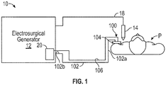
FIG. 1 is a schematic illustration of a monopolar electrosurgical system including an electrosurgical generator, an electrosurgical instrument, and a patient return pad; -
FIG. 2 is a perspective view illustrating the patient return pad ofFIG. 1 ; -
FIG. 3 is a partial bottom view of the patient return pad ofFIG. 1 ; -
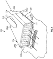
FIG. 4 is a perspective view illustrating another embodiment of a patient return pad for use in the monopolar electrosurgical system; -
FIG. 5 is a front, perspective view illustrating a patient return pad with a foam pad removed; -
FIG. 6 is a bottom view of a return electrode of the patient return pad ofFIG. 4 ; and -
FIG. 7 is a perspective view of yet another embodiment of a patient return pad for use in the monopolar electrosurgical system. - Particular embodiments of the present disclosure are described hereinbelow with reference to the accompanying drawings. In the following description, well-known functions or constructions are not described in detail to avoid obscuring the present disclosure in unnecessary detail.
- A combination patient return pad and surgical smoke evacuator is provided and includes a sheet of material configured to be positioned on a surface adjacent a surgical site, a return electrode formed with or otherwise coupled to the sheet of material, and a suction tube coupled to the sheet of material. The return electrode receives electrosurgical energy from an active electrode and the suction tube removes surgical smoke from the surgical site.
-
FIG. 1 illustrates anelectrosurgical system 10 including an electrosurgical energy source, such as, for example, anelectrosurgical generator 12, anelectrosurgical instrument 14 coupled to thegenerator 12, and apatient return pad 100 coupled to thegenerator 12 via areturn cable 102. Theelectrosurgical generator 12 may be any suitable type of generator and may include a plurality of connectors to accommodate various types of electrosurgical instruments (e.g., monopolar, bipolar, and/or the like). Theelectrosurgical generator 12 may also include avacuum source 20 for drawing surgical smoke from a surgical site. In aspects, thevacuum source 20 andelectrosurgical generator 12 may be separate components. - The
electrosurgical instrument 14 has one or more active electrodes (not explicitly shown) for treating tissue of a patient P. Theinstrument 14 may be a monopolar instrument including one or more active electrodes (such as, for example, an electrosurgical cutting probe, ablation electrode(s), and/or the like). Electrosurgical RF energy is supplied to theinstrument 14 by thegenerator 12 via an activeelectrosurgical cable 18, which is connected to an active output terminal, allowing theinstrument 14 to coagulate, ablate and/or otherwise treat tissue. - With reference to
FIGS. 1-3 , thepatient return pad 100 is a combination patient return pad and smoke evacuator and generally includes ahead 104, thereturn cable 102, and asuction tube 106 supported by thehead 104. Thehead 104 may have a square shape, a triangular shape, or any other suitable shape. Thehead 104 has an openedfront end 104a and an openedrear end 104b. A vacuum pathway V is defined between thefront 104a andrear ends 104b of thehead 104 and extends in the direction toward therear end 104b. - The
head 104 includes apliable sheet 108 or surface, such as, for example, fabric, plastic, or any other suitable material to facilitate return pad operation. Thepliable sheet 108 of thehead 104 has atop surface 108a, and abottom surface 108b configured to face and attach to a tissue surface of a patient located adjacent a surgical site. Thebottom surface 108b of thepliable sheet 108 has aninterior section 110 and an outerperipheral section 112 partially surrounding theinterior section 110. Theinterior section 110 may be recessed relative to the outerperipheral section 112 to define acavity 114. As such, upon attaching the outerperipheral section 112 of thebottom surface 108b to a tissue surface (e.g., skin of a patient), theinterior section 110 of thebottom surface 108b is elevated above the tissue surface to allow air (e.g., surgical smoke) to pass from the openedfront end 104a of thehead 104 to the openedrear end 104b of thehead 104. - In aspects, the
head 104 may include apad 116, such as, for example, a foam pad, received in thecavity 114 to assist in maintaining thecavity 114 open when thebottom surface 108b is attached to a surface. In aspects, thepad 116 may be fabricated from any suitable material and may be conductive or non-conductive. Thepad 116 may be coated with an adherent film, such as, for example, polyethylene. The outerperipheral section 112 of thebottom surface 108b of thepliable sheet 108 has an electrically-conductive adhesive coating 118 (FIG. 3 ) disposed thereon. In aspects, the adhesive 118 may be a liquid, a gel, a film, or the like. - The
head 104 includes areturn electrode 120 attached to the outerperipheral section 112 of thebottom surface 108b and may have the same shape as the outerperipheral section 112 or may extend over the outerperipheral section 112 and the entire bottom surface of thepad 116. In some aspects, thepad 116 may be fabricated from a conductive material so as to act as the return electrode. Thereturn electrode 120 may be a sheet, a wire, or a coating and may be made from materials that include aluminum, copper, mylar, metalized mylar or other suitable conductive material. Thereturn electrode 120 may also include an insulator, glue, a conductive adhesive, gel or other material that is configured to attach thereturn electrode 120 to tissue and/or to facilitate the transfer of electrosurgical energy to the patient's skin. It is contemplated that thereturn electrode 120 and the outerperipheral section 112 have a sufficient surface area to conduct electrosurgical energy to the patient's skin without causing damage to the skin. Thehead 104 may further include a backing 122 (FIG. 2 ) that covers thebottom surface 108b of thepliable sheet 108. Thebacking 122 may be selectively removed (e.g., peeled) from thebottom surface 108b to expose the adhesive 118. - The
return electrode 120 has thereturn lead 102 extending therefrom. In particular, thereturn lead 102, which may be a wire or a cable, has afirst end portion 102a attached to thereturn electrode 120, and asecond end portion 102b (FIG. 1 ) attached to theelectrosurgical generator 12. Thereturn lead 102 transfers electrosurgical energy received by thereturn electrode 120 to theelectrosurgical generator 12. - The
suction tube 106 of thepatient return pad 100 has afirst end portion 106a configured to be coupled to the vacuum source 20 (FIG. 1 ) and asecond end portion 106b configured to be either permanently coupled or detachably coupled to therear end 104b of thehead 104. Thesuction tube 106 defines alongitudinal channel 124 therethrough to allow for the passage of surgical smoke. Thesecond end portion 106b of thesuction tube 106 may have aconnector 126 attached thereto that couples thesuction tube 106 to thehead 104. In aspects, thesecond end portion 106b of thesuction tube 106 may be received in therear end 104b of thehead 104. Theconnector 126 extends through the openrear end 104b of thehead 104 and defines anopening 128 in fluid communication with thecavity 114, such that surgical smoke may pass from thecavity 114 and into thesuction tube 106 via theopening 128. Theconnector 126 may have aflat bottom surface 130 that is coplanar with the outerperipheral section 112 of thebottom surface 108b of thepliable sheet 108 to prevent air gaps from forming between thebottom surface 108b and a tissue surface. Thereturn lead 102 may extend through thechannel 124 of thesuction tube 106, around thesuction tube 106, or run alongside of and separate from thesuction tube 106. - During an electrosurgical procedure, the backing 122 of the
head 104 of thepatient return pad 100 is removed and thebottom surface 108b of thepliable sheet 108 of thehead 104 is placed at a location adjacent the surgical site and in contact with tissue of a patient P (e.g., skin). In aspects where only the vacuum function of thehead 104 is desired, thebottom surface 108b of thepliable sheet 108 may be placed on a surgical drape or other suitable surface adjacent the surgical site. The adhesive 118 on the outerperipheral section 112 of thebottom surface 108b fixes the outerperipheral section 112 to the patient's skin. Thepad 116 of thehead 104 also contacts the skin surface, whereby theinterior section 110 is maintained in spaced relation from the skin surface and thefront end 104a of thehead 104 is maintained in an opened state. Due to thereturn electrode 120 being attached to the outerperipheral section 112, thereturn electrode 120 is placed in contact with or otherwise electrically connected to the skin via the adhesive 118 (e.g., conductive adhesive). - The monopolar electrode of the
surgical instrument 14 may be activated to treat tissue. During treatment, the electrosurgical energy passes from thegenerator 12, through theelectrosurgical instrument 14 and into the patient P to treat the tissue. The electrosurgical energy then travels from the tissue back to theelectrosurgical generator 12 via thereturn electrode 120 in thepatient return pad 100. During the procedure, thevacuum source 20 may be activated to clear any smoke or debris from the surgical field while thefoam pad 116 prevents debris from entering thecavity 114. In aspects, thevacuum source 20 may be activated prior to treating tissue and the generation of smoke. Upon activating thevacuum source 20, a suction pathway is generated and carries the surgical smoke from the surgical field and into thecavity 114 via thefront end 104a of thehead 104. The surgical smoke passes into thesuction tube 106 via theopening 128 in theconnector 126. In this way, thepatient return pad 100 functions both as a return electrode for receiving electrosurgical energy from the active electrode and as a surgical smoke evacuator. Thevacuum source 20 may remain on for a selected period of time after activation of thegenerator 12 has ceased. - With reference to
FIGS. 4-6 , another embodiment of a combination patient return pad andsmoke evacuator 200 is illustrated and generally includes a head, such as, for example, ahousing 204, areturn electrode 220 attached to thehousing 204, and a suction tube, such as, for example, the suction tube 106 (FIG. 2 ) supported by thehousing 204. Thehousing 204 may have a box-shape or any other suitable shape and has an openedfront end 204a and a closedrear end 204b. In aspects, thefront end 204a may be planar (FIG. 4 ) or have a curved or scooped configuration (FIG. 5 ) to better allow for thefront end 204a to surround a surgical opening. - A vacuum pathway is defined between the front 204a and
rear ends 204b of thehousing 204 and extends in the direction toward therear end 204b. Thehousing 204 has atop surface 208a, abottom surface 208b configured to face a tissue surface of a patient, and a pair ofside walls housing 204 may include apad 216, such as, for example, a foam pad, received in a cavity 214 (FIG. 5 ) defined by thehousing 204 to prevent debris from entering thecavity 214. Thehousing 204 has avacuum connector 216 coupled to thetop surface 208a and in fluid communication with thecavity 214. The suction tube 106 (FIG. 2 ) is configured to couple to thevacuum connector 218 to fluidly communicate with the openedfront end 204a of thehousing 204. - The
return electrode 220 may be a split return electrode pad and is attached to thebottom surface 208b of thehousing 204. Thereturn electrode 220 may be a sheet, a wire, or a coating and may be made from materials that include aluminum, copper, mylar, metalized mylar or other suitable conductive material. Thereturn electrode 220 has abottom surface 222 having coated thereon an electrically-conductive adhesive (e.g., a conductive adhesive hydrogel) or other material that is configured to attach thereturn electrode 220 to tissue. A backing (not explicitly shown) may be provided that covers thebottom surface 222 of thereturn electrode 220. The backing may be selectively removed (e.g., peeled) from thebottom surface 222 to expose the adhesive. - The
return electrode 222 has a pair of return leads 224, 226 extending therefrom. In particular, the return leads 224, 226, which may be wires or cables, have a first end portion attached to thereturn electrode 220, and a second end portion attached to the electrosurgical generator 12 (FIG. 1 ). The return leads 224, 226 transfer electrosurgical energy received by thereturn electrode 220 to theelectrosurgical generator 12. In aspects, only one return lead may be provided. - With reference to
FIG. 7 , yet another embodiment of a combination return pad andsmoke evacuator 300 is illustrated and generally includes a head, such as, for example, ahousing 304, areturn electrode 320 attached to thehousing 304, a suction tube, such as, for example, the suction tube 106 (FIG. 2 ) supported by thehousing 304, and aperforated foam pad 316 supported on thereturn electrode 320. Thehousing 304 has an openedfront end portion 304a and a closedrear end portion 304b. Thehousing 304 defines a cavity (not explicitly shown) therein configured to be in communication with the suction tube 106 (FIG. 2 ) via avacuum connector 318. In aspects, thevacuum connector 318 may be directly attached to thefoam pad 316. In aspects, thehousing 304 may cover an upper surface and lateral sides of thefoam pad 316. - The
return electrode 320 may be a flat sheet of material covering abottom surface 319 of thehousing 304 and extending distally from thefront end portion 304a. Thefoam pad 316 is supported on thereturn electrode 320 and covers the openedfront end portion 304a of thehousing 304. Thefoam pad 316 has a plurality ofperforations 324 defining a plurality ofremovable sections 323 to allow for the customization of thefoam pad 316. Theremovable sections 323 may include acorresponding section 325 of thereturn electrode 320, such that upon removing theremovable sections 323, anopening 327 may be formed in thesmoke evacuator 300. Theopening 327 may be positioned over a surgical site or access opening to surround the outer periphery of the access opening with thesmoke evacuator 300. - It should be understood that the foregoing description is only illustrative of the present disclosure. Various alternatives and modifications can be devised by those skilled in the art without departing from the disclosure. Accordingly, the present disclosure is intended to embrace all such alternatives, modifications and variances. The embodiments described with reference to the attached drawing figures are presented only to demonstrate certain examples of the disclosure. Other elements, steps, methods, and techniques that are insubstantially different from those described above and/or in the appended claims are also intended to be within the scope of the disclosure.
- The invention may be described by reference to the following numbered paragraphs: -
- 1. A patient return pad, comprising:
- a sheet having a bottom surface;
- a return electrode coupled to the bottom surface of the sheet and configured to receive electrosurgical energy from an active electrode; and
- a suction tube configured to be coupled to the sheet for vacuuming surgical smoke.
- 2. The patient return pad according to paragraph 1, wherein the bottom surface of the sheet includes an interior section and an outer peripheral section at least partially surrounding the interior section, the return electrode coupled to the outer peripheral section of the bottom surface.
- 3. The patient return pad according to paragraph 2, wherein the suction tube has an end portion attached to the sheet and defining an opening in communication with the interior section of the sheet.
- 4. The patient return pad according to paragraph 3, wherein the interior section is recessed relative to the outer peripheral section, such that the bottom surface of the sheet defines a cavity therein, the opening of the end portion in fluid communication with the cavity.
- 5. The patient return pad according to paragraph 4, further comprising a foam pad received in the cavity.
- 6. The patient return pad according to paragraph 2, wherein the bottom surface of the sheet is configured to form a cavity between the interior section of the bottom surface and a tissue surface upon attaching the outer peripheral section of the bottom surface to the tissue surface.
- 7. The patient return pad according to paragraph 2, further comprising a conductive adhesive disposed on the outer peripheral section.
- 8. The patient return pad according to paragraph 1, wherein the sheet has a front end and a rear end and defines a vacuum path from the front end toward the rear end, the suction tube coupled to the rear end.
- 9. The patient return pad according to paragraph 1, further comprising a return lead having a first end portion coupled to the return electrode and a second end portion configured to electrically couple the return electrode to an electrosurgical energy source.
- 10. The patient return pad according to paragraph 9, wherein the return lead extends through or over the suction tube.
- 11. A combination patient return pad and surgical smoke evacuator, comprising:
- a housing defining a cavity therein configured to receive suction, the housing having a bottom surface; and
- a return electrode coupled to the bottom surface of the housing, the return electrode having an adherent and conductive bottom surface configured to receive electrosurgical energy from an active electrode.
- 12. The combination patient return pad and surgical smoke evacuator according to paragraph 11, further comprising a suction tube having a first end portion configured to be coupled to a vacuum source and a second end portion coupled to the housing and in fluid communication with the cavity for vacuuming surgical smoke through the cavity.
- 13. The combination patient return pad and surgical smoke evacuator according to paragraph 11, further comprising a foam pad received in the cavity.
- 14. The combination patient return pad and surgical smoke evacuator according to paragraph 11, wherein the housing has an opened front end and a rear end and defines a vacuum path from the front end toward the rear end.
- 15. The combination patient return pad and surgical smoke evacuator according to paragraph 11, further comprising a return lead having a first end portion coupled to the return electrode and a second end portion configured to electrically couple the return electrode to an electrosurgical energy source.
Claims (15)
- A patient return pad, comprising:a sheet having a bottom surface;a return electrode coupled to the bottom surface of the sheet and configured to receive electrosurgical energy from an active electrode; anda suction tube configured to be coupled to the sheet for vacuuming surgical smoke.
- The patient return pad according to claim 1, wherein the bottom surface of the sheet includes an interior section and an outer peripheral section at least partially surrounding the interior section, the return electrode coupled to the outer peripheral section of the bottom surface.
- The patient return pad according to claim 2, wherein the suction tube has an end portion attached to the sheet and defining an opening in communication with the interior section of the sheet.
- The patient return pad according to claim 3, wherein the interior section is recessed relative to the outer peripheral section, such that the bottom surface of the sheet defines a cavity therein, the opening of the end portion in fluid communication with the cavity.
- The patient return pad according to claim 4, further comprising a foam pad received in the cavity.
- The patient return pad according to any of claims 2 to 5, wherein the bottom surface of the sheet is configured to form a cavity between the interior section of the bottom surface and a tissue surface upon attaching the outer peripheral section of the bottom surface to the tissue surface.
- The patient return pad according to any of claims 2 to 6, further comprising a conductive adhesive disposed on the outer peripheral section.
- The patient return pad according to any preceding claim, wherein the sheet has a front end and a rear end and defines a vacuum path from the front end toward the rear end, the suction tube coupled to the rear end.
- The patient return pad according to any preceding claim, further comprising a return lead having a first end portion coupled to the return electrode and a second end portion configured to electrically couple the return electrode to an electrosurgical energy source.
- The patient return pad according to claim 9, wherein the return lead extends through or over the suction tube.
- A combination patient return pad and surgical smoke evacuator, comprising:a housing defining a cavity therein configured to receive suction, the housing having a bottom surface; anda return electrode coupled to the bottom surface of the housing, the return electrode having an adherent and conductive bottom surface configured to receive electrosurgical energy from an active electrode.
- The combination patient return pad and surgical smoke evacuator according to claim 11, further comprising a suction tube having a first end portion configured to be coupled to a vacuum source and a second end portion coupled to the housing and in fluid communication with the cavity for vacuuming surgical smoke through the cavity.
- The combination patient return pad and surgical smoke evacuator according to claim 11 or 12, further comprising a foam pad received in the cavity.
- The combination patient return pad and surgical smoke evacuator according to claim 11, 12 or 13 wherein the housing has an opened front end and a rear end and defines a vacuum path from the front end toward the rear end.
- The combination patient return pad and surgical smoke evacuator according to claim 11, 12, 13 or 14 further comprising a return lead having a first end portion coupled to the return electrode and a second end portion configured to electrically couple the return electrode to an electrosurgical energy source.
Applications Claiming Priority (1)
| Application Number | Priority Date | Filing Date | Title |
|---|---|---|---|
| US16/711,603 US11364076B2 (en) | 2019-12-12 | 2019-12-12 | Monopolar return pad |
Publications (2)
| Publication Number | Publication Date |
|---|---|
| EP3834760A2 true EP3834760A2 (en) | 2021-06-16 |
| EP3834760A3 EP3834760A3 (en) | 2021-08-18 |
Family
ID=73740248
Family Applications (1)
| Application Number | Title | Priority Date | Filing Date |
|---|---|---|---|
| EP20212152.1A Withdrawn EP3834760A3 (en) | 2019-12-12 | 2020-12-07 | Monopolar return pad |
Country Status (2)
| Country | Link |
|---|---|
| US (2) | US11364076B2 (en) |
| EP (1) | EP3834760A3 (en) |
Families Citing this family (1)
| Publication number | Priority date | Publication date | Assignee | Title |
|---|---|---|---|---|
| US11364076B2 (en) | 2019-12-12 | 2022-06-21 | Covidien Lp | Monopolar return pad |
Family Cites Families (104)
| Publication number | Priority date | Publication date | Assignee | Title |
|---|---|---|---|---|
| US3122171A (en) | 1960-10-19 | 1964-02-25 | Carlon Products Corp | Flexible plastic tubing |
| US3720209A (en) * | 1968-03-11 | 1973-03-13 | Medical Plastics Inc | Plate electrode |
| US3913583A (en) | 1974-06-03 | 1975-10-21 | Sybron Corp | Control circuit for electrosurgical units |
| FR2276027A1 (en) | 1974-06-25 | 1976-01-23 | Medical Plastics Inc | ELECTRICAL CONNECTION FOR FLAT ELECTRODE |
| US3923063A (en) | 1974-07-15 | 1975-12-02 | Sybron Corp | Pulse control circuit for electrosurgical units |
| US4126137A (en) | 1977-01-21 | 1978-11-21 | Minnesota Mining And Manufacturing Company | Electrosurgical unit |
| US4166465A (en) | 1977-10-17 | 1979-09-04 | Neomed Incorporated | Electrosurgical dispersive electrode |
| US4200104A (en) | 1977-11-17 | 1980-04-29 | Valleylab, Inc. | Contact area measurement apparatus for use in electrosurgery |
| US4188927A (en) | 1978-01-12 | 1980-02-19 | Valleylab, Inc. | Multiple source electrosurgical generator |
| CA1105565A (en) | 1978-09-12 | 1981-07-21 | Kaufman (John G.) Hospital Products Ltd. | Electrosurgical electrode |
| US4267840A (en) * | 1979-01-08 | 1981-05-19 | Johnson & Johnson | Electrosurgical grounding pad |
| ZA803166B (en) | 1979-06-15 | 1981-05-27 | Ndm Corp | Capacitively coupled indifferent electrode |
| US4669468A (en) | 1979-06-15 | 1987-06-02 | American Hospital Supply Corporation | Capacitively coupled indifferent electrode |
| US4303073A (en) | 1980-01-17 | 1981-12-01 | Medical Plastics, Inc. | Electrosurgery safety monitor |
| US4494541A (en) | 1980-01-17 | 1985-01-22 | Medical Plastics, Inc. | Electrosurgery safety monitor |
| US4387714A (en) | 1981-05-13 | 1983-06-14 | Purdue Research Foundation | Electrosurgical dispersive electrode |
| FR2516782B1 (en) | 1981-11-20 | 1985-09-27 | Alm | HIGH FREQUENCY CURRENT ELECTRO-SURGICAL APPARATUS AND METHOD OF IMPLEMENTING |
| DE3206947A1 (en) | 1982-02-26 | 1983-09-15 | Erbe Elektromedizin GmbH, 7400 Tübingen | Neutral electrode for radio-frequency surgery |
| CA1219642A (en) | 1984-04-18 | 1987-03-24 | Monique Frize | Multi-element electrosurgical indifferent electrode with temperature balancing resistors |
| DE3523871C3 (en) | 1985-07-04 | 1994-07-28 | Erbe Elektromedizin | High frequency surgical device |
| DE3544443C2 (en) | 1985-12-16 | 1994-02-17 | Siemens Ag | HF surgery device |
| ES8800028A1 (en) | 1986-06-25 | 1987-11-01 | Fuchelman Sa | Contour type electrosurgical dispersive electrode. |
| EP0262888A3 (en) | 1986-09-27 | 1989-10-18 | Ronald Davidson Clark | Surgical diathermy apparatus |
| US4799480A (en) | 1987-08-04 | 1989-01-24 | Conmed | Electrode for electrosurgical apparatus |
| DE3728906A1 (en) | 1987-08-29 | 1989-03-09 | Asea Brown Boveri | METHOD FOR DETECTING A CURRENT FLOWS CURRENTLY FLOWING FROM THE HUMAN BODY AND CIRCUIT ARRANGEMENT FOR IMPLEMENTING THE METHOD |
| DE58908600D1 (en) | 1989-04-01 | 1994-12-08 | Erbe Elektromedizin | Device for monitoring the application of neutral electrodes in high-frequency surgery. |
| US5015243A (en) | 1989-06-30 | 1991-05-14 | Michael Schifano | Means for removing smoke from an operative site |
| US5312401A (en) | 1991-07-10 | 1994-05-17 | Electroscope, Inc. | Electrosurgical apparatus for laparoscopic and like procedures |
| US5688269A (en) | 1991-07-10 | 1997-11-18 | Electroscope, Inc. | Electrosurgical apparatus for laparoscopic and like procedures |
| GB9119695D0 (en) | 1991-09-14 | 1991-10-30 | Smiths Industries Plc | Electrosurgery equipment |
| DE4238263A1 (en) | 1991-11-15 | 1993-05-19 | Minnesota Mining & Mfg | Adhesive comprising hydrogel and crosslinked polyvinyl:lactam - is used in electrodes for biomedical application providing low impedance and good mechanical properties when water and/or moisture is absorbed from skin |
| EP0558051B1 (en) | 1992-02-27 | 1996-10-16 | FISHER & PAYKEL LIMITED | Cable termination status detection |
| DE4231236C2 (en) | 1992-09-18 | 1995-08-31 | Aesculap Ag | Flat electrode for high-frequency surgery |
| US5370645A (en) | 1993-04-19 | 1994-12-06 | Valleylab Inc. | Electrosurgical processor and method of use |
| US5695494A (en) | 1994-12-22 | 1997-12-09 | Valleylab Inc | Rem output stage topology |
| US5678545A (en) | 1995-05-04 | 1997-10-21 | Stratbucker; Robert A. | Anisotropic adhesive multiple electrode system, and method of use |
| US5720744A (en) | 1995-06-06 | 1998-02-24 | Valleylab Inc | Control system for neurosurgery |
| US5868742A (en) | 1995-10-18 | 1999-02-09 | Conmed Corporation | Auxiliary reference electrode and potential referencing technique for endoscopic electrosurgical instruments |
| US7267675B2 (en) | 1996-01-05 | 2007-09-11 | Thermage, Inc. | RF device with thermo-electric cooler |
| US5836942A (en) | 1996-04-04 | 1998-11-17 | Minnesota Mining And Manufacturing Company | Biomedical electrode with lossy dielectric properties |
| US5947961A (en) | 1996-05-10 | 1999-09-07 | Minnesota Mining And Manufacturing Company | Biomedical electrode having skin-equilibrating adhesive at its perimeter and method for using same |
| DE19643127A1 (en) | 1996-10-18 | 1998-04-23 | Berchtold Gmbh & Co Geb | High frequency surgical device and method for its operation |
| US5830212A (en) | 1996-10-21 | 1998-11-03 | Ndm, Inc. | Electrosurgical generator and electrode |
| US6454764B1 (en) | 1996-10-30 | 2002-09-24 | Richard P. Fleenor | Self-limiting electrosurgical return electrode |
| US6544258B2 (en) * | 1996-10-30 | 2003-04-08 | Mega-Dyne Medical Products, Inc. | Pressure sore pad having self-limiting electrosurgical return electrode properties and optional heating/cooling capabilities |
| US7166102B2 (en) | 1996-10-30 | 2007-01-23 | Megadyne Medical Products, Inc. | Self-limiting electrosurgical return electrode |
| AU731933B2 (en) | 1996-10-30 | 2001-04-05 | Megadyne Medical Products, Inc. | Reusable electrosurgical return pad |
| US6053910A (en) | 1996-10-30 | 2000-04-25 | Megadyne Medical Products, Inc. | Capacitive reusable electrosurgical return electrode |
| US6582424B2 (en) | 1996-10-30 | 2003-06-24 | Megadyne Medical Products, Inc. | Capacitive reusable electrosurgical return electrode |
| ATE295629T1 (en) | 1996-12-10 | 2005-05-15 | David W Caldwell | DIFFERENTIAL TOUCH SENSOR AND CONTROL CIRCUIT THEREOF |
| CA2285469A1 (en) | 1997-04-04 | 1998-10-15 | Samuel G. Netherly | Method and apparatus for controlling contact of biomedical electrodes with patient skin |
| US5846254A (en) | 1997-04-08 | 1998-12-08 | Ethicon Endo-Surgery, Inc. | Surgical instrument for forming a knot |
| DE19717411A1 (en) | 1997-04-25 | 1998-11-05 | Aesculap Ag & Co Kg | Monitoring of thermal loading of patient tissue in contact region of neutral electrode of HF treatment unit |
| US6007532A (en) | 1997-08-29 | 1999-12-28 | 3M Innovative Properties Company | Method and apparatus for detecting loss of contact of biomedical electrodes with patient skin |
| DE19801173C1 (en) | 1998-01-15 | 1999-07-15 | Kendall Med Erzeugnisse Gmbh | Clamp connector for film electrodes |
| US6942650B1 (en) * | 1998-04-17 | 2005-09-13 | Innovative Surgical Technologies, Inc. | Evacuator |
| ATE288709T1 (en) | 1998-11-16 | 2005-02-15 | Ioan Cosmescu | MULTIFUNCTIONAL TELESCOPIC ELECTROSURGICAL DEVICE |
| EP1135073A4 (en) | 1998-11-30 | 2003-01-15 | Megadyne Med Prod Inc | Resistive reusable electrosurgical return electrode |
| WO2000053113A1 (en) | 1999-03-09 | 2000-09-14 | Thermage, Inc. | Apparatus and method for treatment of tissue |
| AT407486B (en) | 1999-04-29 | 2001-03-26 | Leonhard Lang Kg | MEDICAL ELECTRODE |
| US6258085B1 (en) | 1999-05-11 | 2001-07-10 | Sherwood Services Ag | Electrosurgical return electrode monitor |
| US6342826B1 (en) | 1999-08-11 | 2002-01-29 | Therm-O-Disc, Incorporated | Pressure and temperature responsive switch assembly |
| US7771422B2 (en) | 2002-06-06 | 2010-08-10 | Nuortho Surgical, Inc. | Methods and devices for electrosurgery |
| US20030139741A1 (en) | 2000-10-31 | 2003-07-24 | Gyrus Medical Limited | Surgical instrument |
| GB2374532B (en) | 2001-02-23 | 2004-10-06 | Smiths Group Plc | Electrosurgery apparatus |
| US6695838B2 (en) * | 2001-09-28 | 2004-02-24 | Ethicon, Inc. | System and method for performing cardiac tissue ablation |
| US6860881B2 (en) | 2002-09-25 | 2005-03-01 | Sherwood Services Ag | Multiple RF return pad contact detection system |
| US7105000B2 (en) | 2003-03-25 | 2006-09-12 | Ethicon Endo-Surgery, Inc. | Surgical jaw assembly with increased mechanical advantage |
| DE10328514B3 (en) | 2003-06-20 | 2005-03-03 | Aesculap Ag & Co. Kg | Endoscopic surgical scissor instrument has internal pushrod terminating at distal end in transverse cylindrical head |
| US6891488B1 (en) | 2003-10-30 | 2005-05-10 | Intel Corporation | Sigma-delta conversion with analog, nonvolatile trimmed quantized feedback |
| US7169145B2 (en) | 2003-11-21 | 2007-01-30 | Megadyne Medical Products, Inc. | Tuned return electrode with matching inductor |
| DE102004010940B4 (en) | 2004-03-05 | 2012-01-26 | Erbe Elektromedizin Gmbh | Neutral electrode for HF surgery |
| EP1744695B1 (en) | 2004-04-16 | 2012-03-21 | Sydney West Area Health Service | Biomedical return electrode having thermochromic layer |
| DE102004025613B4 (en) | 2004-05-25 | 2008-08-07 | Erbe Elektromedizin Gmbh | Method and measuring device for determining the transition impedance between two partial electrodes of a divided neutral electrode |
| US7422589B2 (en) | 2004-08-17 | 2008-09-09 | Encision, Inc. | System and method for performing an electrosurgical procedure |
| US7465302B2 (en) | 2004-08-17 | 2008-12-16 | Encision, Inc. | System and method for performing an electrosurgical procedure |
| US20060041252A1 (en) | 2004-08-17 | 2006-02-23 | Odell Roger C | System and method for monitoring electrosurgical instruments |
| US7771419B2 (en) | 2004-10-05 | 2010-08-10 | Granite Advisory Services, Inc. | Biomedical dispersive electrode |
| US20060079872A1 (en) | 2004-10-08 | 2006-04-13 | Eggleston Jeffrey L | Devices for detecting heating under a patient return electrode |
| CA2541037A1 (en) | 2005-03-31 | 2006-09-30 | Sherwood Services Ag | Temperature regulating patient return electrode and return electrode monitoring system |
| US7736359B2 (en) | 2006-01-12 | 2010-06-15 | Covidien Ag | RF return pad current detection system |
| US20070167942A1 (en) | 2006-01-18 | 2007-07-19 | Sherwood Services Ag | RF return pad current distribution system |
| US20070244478A1 (en) | 2006-04-18 | 2007-10-18 | Sherwood Services Ag | System and method for reducing patient return electrode current concentrations |
| DE102007020583B4 (en) | 2006-07-19 | 2012-10-11 | Erbe Elektromedizin Gmbh | Electrode device with an impedance measuring device and method for producing such an electrode device |
| US20080047064A1 (en) * | 2006-08-02 | 2008-02-28 | Theran Michael E | Surgical equipment supporting frames and attachments for same |
| US7637907B2 (en) | 2006-09-19 | 2009-12-29 | Covidien Ag | System and method for return electrode monitoring |
| US8080007B2 (en) | 2007-05-07 | 2011-12-20 | Tyco Healthcare Group Lp | Capacitive electrosurgical return pad with contact quality monitoring |
| US8231614B2 (en) | 2007-05-11 | 2012-07-31 | Tyco Healthcare Group Lp | Temperature monitoring return electrode |
| US8388612B2 (en) | 2007-05-11 | 2013-03-05 | Covidien Lp | Temperature monitoring return electrode |
| US8187263B2 (en) | 2008-02-04 | 2012-05-29 | Tyco Healthcare Group Lp | System and method for return electrode monitoring |
| US8523853B2 (en) | 2008-02-05 | 2013-09-03 | Covidien Lp | Hybrid contact quality monitoring return electrode |
| US8342459B2 (en) | 2008-03-06 | 2013-01-01 | Covidien Lp | Wire organizer |
| US20090234352A1 (en) | 2008-03-17 | 2009-09-17 | Tyco Healthcare Group Lp | Variable Capacitive Electrode Pad |
| US9987072B2 (en) | 2008-03-17 | 2018-06-05 | Covidien Lp | System and method for detecting a fault in a capacitive return electrode for use in electrosurgery |
| US7699395B1 (en) | 2008-12-15 | 2010-04-20 | Bozarth John V | High chair apparatus |
| US8298225B2 (en) | 2009-03-19 | 2012-10-30 | Tyco Healthcare Group Lp | System and method for return electrode monitoring |
| US8882767B2 (en) * | 2009-04-24 | 2014-11-11 | Megadyne Medical Products, Inc. | Electrosurgical instrument with adjustable utility conduit |
| US10010693B2 (en) | 2011-06-28 | 2018-07-03 | Fisher & Paykel Healthcare Limited | Medical tubing |
| GB201308904D0 (en) * | 2013-05-17 | 2013-07-03 | Gyrus Medical Ltd | Electrosurgical instrument and system |
| US11076909B2 (en) | 2015-09-25 | 2021-08-03 | Gyrus Acmi, Inc. | Multifunctional medical device |
| US11617611B2 (en) | 2016-06-17 | 2023-04-04 | Megadayne Medical Products, Inc. | Hand-held instrument with dual zone fluid removal |
| US11389225B2 (en) | 2017-11-29 | 2022-07-19 | Megadyne Medical Products, Inc. | Smoke evacuation device remote activation system |
| US11553959B2 (en) * | 2018-03-29 | 2023-01-17 | Boston Scientific Scimed, Inc. | Methods and devices for performing electrosurgery |
| US11364076B2 (en) | 2019-12-12 | 2022-06-21 | Covidien Lp | Monopolar return pad |
-
2019
- 2019-12-12 US US16/711,603 patent/US11364076B2/en active Active
-
2020
- 2020-12-07 EP EP20212152.1A patent/EP3834760A3/en not_active Withdrawn
-
2022
- 2022-06-03 US US17/831,681 patent/US12186014B2/en active Active
Also Published As
| Publication number | Publication date |
|---|---|
| US11364076B2 (en) | 2022-06-21 |
| US20210177513A1 (en) | 2021-06-17 |
| US12186014B2 (en) | 2025-01-07 |
| EP3834760A3 (en) | 2021-08-18 |
| US20220287771A1 (en) | 2022-09-15 |
Similar Documents
| Publication | Publication Date | Title |
|---|---|---|
| EP1852080B1 (en) | Soft tissue RF transection and resection device | |
| US7879034B2 (en) | Internally located return electrode electrosurgical apparatus, system and method | |
| US7223267B2 (en) | Ultrasonic probe with detachable slidable cauterization forceps | |
| US7066936B2 (en) | Surgical cutting and tissue vaporizing instrument | |
| US6692445B2 (en) | Biopsy sampler | |
| US8277445B2 (en) | Ablation device | |
| US5261905A (en) | Spatula-hook instrument for laparoscopic cholecystectomy | |
| EP1439793B1 (en) | Self-wetting, dry-field bipolar electrodes for endoscopic surgery | |
| US7611511B2 (en) | Bipolar medical instrument and electrosurgical system comprising such an instrument | |
| US20050143730A1 (en) | RF cauterization and ultrasonic ablation instrument with multi-hole collar and electrode mounting sleeve | |
| US8845576B2 (en) | Electrosurgical tool | |
| JPS6459B2 (en) | ||
| JPH04221539A (en) | Bipolar surgical scalpel for sampling internal mammary artery | |
| WO2002053049A2 (en) | Shapeable electrosurgical scalpel | |
| JPH01195850A (en) | Freely extensible type electric knife surgical apparatus and method | |
| US5741250A (en) | Electrosurgical instrument for ear surgery | |
| US12186014B2 (en) | Monopolar return pad including a pathway for evacuating surgical smoke | |
| JPH119610A (en) | Endoscope cautery | |
| JP3244648B2 (en) | Endoscope cautery | |
| JP5011527B2 (en) | Microwave surgical device | |
| JPH0380847A (en) | Patient electrode for high frequency treatment | |
| JPH06327695A (en) | Device for high frequency electric scalpel |
Legal Events
| Date | Code | Title | Description |
|---|---|---|---|
| PUAI | Public reference made under article 153(3) epc to a published international application that has entered the european phase |
Free format text: ORIGINAL CODE: 0009012 |
|
| STAA | Information on the status of an ep patent application or granted ep patent |
Free format text: STATUS: THE APPLICATION HAS BEEN PUBLISHED |
|
| AK | Designated contracting states |
Kind code of ref document: A2 Designated state(s): AL AT BE BG CH CY CZ DE DK EE ES FI FR GB GR HR HU IE IS IT LI LT LU LV MC MK MT NL NO PL PT RO RS SE SI SK SM TR |
|
| PUAL | Search report despatched |
Free format text: ORIGINAL CODE: 0009013 |
|
| AK | Designated contracting states |
Kind code of ref document: A3 Designated state(s): AL AT BE BG CH CY CZ DE DK EE ES FI FR GB GR HR HU IE IS IT LI LT LU LV MC MK MT NL NO PL PT RO RS SE SI SK SM TR |
|
| RIC1 | Information provided on ipc code assigned before grant |
Ipc: A61B 18/16 20060101AFI20210709BHEP Ipc: A61M 1/00 20060101ALN20210709BHEP |
|
| STAA | Information on the status of an ep patent application or granted ep patent |
Free format text: STATUS: REQUEST FOR EXAMINATION WAS MADE |
|
| 17P | Request for examination filed |
Effective date: 20220121 |
|
| RBV | Designated contracting states (corrected) |
Designated state(s): AL AT BE BG CH CY CZ DE DK EE ES FI FR GB GR HR HU IE IS IT LI LT LU LV MC MK MT NL NO PL PT RO RS SE SI SK SM TR |
|
| STAA | Information on the status of an ep patent application or granted ep patent |
Free format text: STATUS: THE APPLICATION HAS BEEN WITHDRAWN |
|
| 18W | Application withdrawn |
Effective date: 20240520 |