EP3833943B1 - Auf extinktionsverhältnisfreiem phasenempfindlichem optischem zeitbereichsreflektometer basierendes verteiltes schallerfassungssystem - Google Patents
Auf extinktionsverhältnisfreiem phasenempfindlichem optischem zeitbereichsreflektometer basierendes verteiltes schallerfassungssystem Download PDFInfo
- Publication number
- EP3833943B1 EP3833943B1 EP18869466.5A EP18869466A EP3833943B1 EP 3833943 B1 EP3833943 B1 EP 3833943B1 EP 18869466 A EP18869466 A EP 18869466A EP 3833943 B1 EP3833943 B1 EP 3833943B1
- Authority
- EP
- European Patent Office
- Prior art keywords
- optic
- signal
- power
- cable
- laser
- Prior art date
- Legal status (The legal status is an assumption and is not a legal conclusion. Google has not performed a legal analysis and makes no representation as to the accuracy of the status listed.)
- Active
Links
Images

Classifications
-
- G—PHYSICS
- G01—MEASURING; TESTING
- G01H—MEASUREMENT OF MECHANICAL VIBRATIONS OR ULTRASONIC, SONIC OR INFRASONIC WAVES
- G01H9/00—Measuring mechanical vibrations or ultrasonic, sonic or infrasonic waves by using radiation-sensitive means, e.g. optical means
- G01H9/004—Measuring mechanical vibrations or ultrasonic, sonic or infrasonic waves by using radiation-sensitive means, e.g. optical means using fibre optic sensors
- G01H9/006—Measuring mechanical vibrations or ultrasonic, sonic or infrasonic waves by using radiation-sensitive means, e.g. optical means using fibre optic sensors the vibrations causing a variation in the relative position of the end of a fibre and another element
-
- G—PHYSICS
- G01—MEASURING; TESTING
- G01H—MEASUREMENT OF MECHANICAL VIBRATIONS OR ULTRASONIC, SONIC OR INFRASONIC WAVES
- G01H9/00—Measuring mechanical vibrations or ultrasonic, sonic or infrasonic waves by using radiation-sensitive means, e.g. optical means
-
- G—PHYSICS
- G01—MEASURING; TESTING
- G01D—MEASURING NOT SPECIALLY ADAPTED FOR A SPECIFIC VARIABLE; ARRANGEMENTS FOR MEASURING TWO OR MORE VARIABLES NOT COVERED IN A SINGLE OTHER SUBCLASS; TARIFF METERING APPARATUS; MEASURING OR TESTING NOT OTHERWISE PROVIDED FOR
- G01D5/00—Mechanical means for transferring the output of a sensing member; Means for converting the output of a sensing member to another variable where the form or nature of the sensing member does not constrain the means for converting; Transducers not specially adapted for a specific variable
- G01D5/26—Mechanical means for transferring the output of a sensing member; Means for converting the output of a sensing member to another variable where the form or nature of the sensing member does not constrain the means for converting; Transducers not specially adapted for a specific variable characterised by optical transfer means, i.e. using infrared, visible, or ultraviolet light
- G01D5/32—Mechanical means for transferring the output of a sensing member; Means for converting the output of a sensing member to another variable where the form or nature of the sensing member does not constrain the means for converting; Transducers not specially adapted for a specific variable characterised by optical transfer means, i.e. using infrared, visible, or ultraviolet light with attenuation or whole or partial obturation of beams of light
- G01D5/34—Mechanical means for transferring the output of a sensing member; Means for converting the output of a sensing member to another variable where the form or nature of the sensing member does not constrain the means for converting; Transducers not specially adapted for a specific variable characterised by optical transfer means, i.e. using infrared, visible, or ultraviolet light with attenuation or whole or partial obturation of beams of light the beams of light being detected by photocells
- G01D5/353—Mechanical means for transferring the output of a sensing member; Means for converting the output of a sensing member to another variable where the form or nature of the sensing member does not constrain the means for converting; Transducers not specially adapted for a specific variable characterised by optical transfer means, i.e. using infrared, visible, or ultraviolet light with attenuation or whole or partial obturation of beams of light the beams of light being detected by photocells influencing the transmission properties of an optical fibre
- G01D5/35338—Mechanical means for transferring the output of a sensing member; Means for converting the output of a sensing member to another variable where the form or nature of the sensing member does not constrain the means for converting; Transducers not specially adapted for a specific variable characterised by optical transfer means, i.e. using infrared, visible, or ultraviolet light with attenuation or whole or partial obturation of beams of light the beams of light being detected by photocells influencing the transmission properties of an optical fibre using other arrangements than interferometer arrangements
- G01D5/35354—Sensor working in reflection
- G01D5/35358—Sensor working in reflection using backscattering to detect the measured quantity
- G01D5/35361—Sensor working in reflection using backscattering to detect the measured quantity using elastic backscattering to detect the measured quantity, e.g. using Rayleigh backscattering
Definitions
- the present disclosure relates to a distributed acoustic sensing system structure to eliminate the degradation in distributed acoustic sensing performance encountered due to the finite extinction ratio of the optical elements that are used to generate optical pulses.
- Fiber-optic distributed acoustic sensing based on the phase-OTDR (Optical Time Domain Reflectometer) technique offers a robust and cost-effective solution for monitoring long linear assets, such as oil/gas pipelines, powerlines, railroad tracks and boundaries of medium to large size facilities.
- Fiber-optic DAS can use telecommunication grade fiber optic cables as both the sensing and transmission medium, making it immune to electromagnetic radiation and jamming. As these cables are typically buried underground, DAS based monitoring solutions are robust against manual tampering as well. Furthermore, unlike active sensing solutions such as day-light or IR-cameras, DAS does not require additional power lines to be deployed along the asset.
- Phase-OTDR (or phase sensitive OTDR) is based on precise measurement of a physical phenomenon called Rayleigh scattering that is naturally observed in fiber optic cables [1].
- Rayleigh scattering can be thought of as the partial backscattering of light traveling in the fiber optic cable due to molecular level imperfections that act as micro mirrors, also known as scattering centers.
- Mechanical waves in proximity of a fiber optic cable can physically interact with the cable and cause small but measurable alterations in the naturally observed levels of Rayleigh scattering. By sensing and interpreting these fluctuations in the backscattered light, physical activities such as digging or walking in proximity of a buried fiber optic cable can be detected, and with proper signal processing even be classified [2], [3].
- OTDR is based on sending pulses of incoherent light into a fiber optic cable and measuring the back reflected light intensity at the same cable end.
- Today, OTDR is widely used for distributed measurement of signal loss and detection of broken points along fiber optic cables.
- Traditional OTDR uses incoherent light and therefore can only measure intensity variations along the fiber; it cannot be used for detecting vibrations near the fiber optic cable unless vibrations cause physical damage on the fiber optic cable structure.
- phase sensitive OTDR however, a highly coherent light source is used and reflections from different scattering centers interfere coherently to produce the detected optical power trace [4], [5], [6], [7].
- a mechanical vibration source physically interacts with a fiber optic cable, physical locations of the previously mentioned scattering centers are slightly changed.
- phase shifts affect the cumulative interference pattern for the portion of the fiber optic cable, where mechanical vibrations are applied. As the interference pattern changes so does the resulting light intensity and this change is measured, hence the term phase sensitive OTDR.
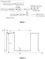
- a typical phase-OTDR DAS system is shown in Figure 1 .
- the light source is a narrow linewidth continuous wave (CW) laser with a specific wavelength selected based on the used fiber optic cable loss characteristics.
- the output of the laser is amplified by an Erbium doped fiber amplifier (EDFA).
- EDFA Erbium doped fiber amplifier
- the amplified optical signal is then sent to the acousto-optic modulator (AOM), which is driven by the RF pulse signal generated by the pulse generator and pulse driver blocks, to create very narrow ( ⁇ 100 ns) optical pulses.
- the generated optic pulses are sent into the sensing fiber through a circulator.
- the optical pulses traveling in the sensing fiber experience random Rayleigh scattering.
- the scattering signals with very similar frequency interfere coherently, which results in a random intensity optical signal.
- Any external acoustic disturbances acting on the fiber that may be caused by walking, digging etc.
- These optical phase changes modulate the optic light intensity, which is detected by the photodetector (PD).
- the photodetected signal is digitized and processed.
- electro-optic modulators EOM
- AOM acousto-optic modulators
- ER Extinction Ratio
- phase-OTDR the aim of using short duration pulses is independently interrogating specific portions of the cable, where the length of the actively interrogated cable portion is specified by the optic pulse width. This is only possible when no light is injected into the fiber optic cable outside of the input light pulse.
- the unwanted leakage optical signal (pulse OFF state or P min in Figure 2 ) invalidates the phase-OTDR sensing principal.
- the interrogated portions of the fiber optic cable cannot be independent, the activities on different portions of the cable may affect each other.
- the backscattered signals coming from the whole fiber optic cable interfere with each other, which affects the overall sensing performance, especially for long cables.
- ER is an inherent limiting factor that has a direct effect on the detection performance of phase-OTDR based DAS systems [8], [9].
- [8] proposes to use the nonlinear Kerr effect for optic pulse generation with extremely high extinction ratio. In this work, it is also theoretically shown that at least 90 dB extinction ratio is required for satisfying sensing performance at long fiber optic cables (> 40 km).
- a high extinction ratio periodic pulse signal generating system based on a feedback structure is introduced.
- a feedback circuit formed by an optical phase shifter, an optical amplifier, a time delay optical fiber, and an adjustable optical fiber delay line is used to feed a part of light output by a modulator back to the input end of the modulator.
- the optical couplers are used to couple optical signals output by a CW laser with the optical modulator, and then repeated modulation is realized.
- Shutter mechanism for reducing optical noise in distributed acoustic sensing system that will be used in wellbore.
- Shutter mechanism is derived by a controller operable to transmit a signal to the shutter to open the shutter for allowing an optical pulse to transmit through the shutter, and close the shutter for preventing an extraneous optical waveform. In that way, the unwanted leakage light due to finite extinction ratio values can be reduced.
- the shutter can be considered as cascading mechanism of multiple optic pulse generator and has the same limitations of EOMs or AOMs.
- GB patent no. GB2442745A multiple groups of pulses with different frequencies are transmitted into the fiber optic cable to detect acoustic waves in the vicinity of buried optical fibers.
- the aim of using multiple pulses with different carrier frequencies is to mitigate the coherence fading problem, which is observed when the coherence length of the laser source is much larger than the pulse length.
- Multiple pulses provide redundancy and increase the probability that at least some of carriers are in a good condition for vibration sensing. This work requires careful selection of the carrier frequency differences between optic pulses and filter design to select the specific optic pulse pair at the receiver side.
- a sequence of optical pulses along an optical fiber of at least two different widths are used for interrogation to obtain a set of fade-resistant phase measurements.
- the proposed interrogation system transmits a sequence of M simultaneously propagating light pulses through the optical fiber using a spatial mode selected from a set of N spatial modes.
- the receiver side detects an environmental perturbation in the optical fiber based on an evaluation of a propagation of the sequence of M light pulses through the optical fiber.
- a modulated pulse is used in interrogation process to realize accurate location and measurement of broadband vibration in a long-distance range. This work does not address the effects of leakage light on the system performance.
- the invention relates to a phase sensitive optical time domain reflectometry based acoustic sensing system according to claim 1 and a phase sensitive optical time domain reflectometry based acoustic sensing method according to claim 14.
- Advantageous embodiments of the invention are described in the dependent claims.
- the invention aims to eliminate the degradation in sensing performance encountered due to the finite extinction ratio of the optical elements that are used to generate optical pulses.
- the classical OTDR and phase-OTDR concepts are merged to generate a modified optic pulse for interrogation with commercially available AOMs or EOMs.
- the characteristics of the light inside the fiber optic cable carry the properties of both classical OTDR and phase-OTDR systems.
- the proposed solution does not require any modifications in the receiver part of the phase-OTDR systems and can easily be used for any type of phase-OTDR system structure.
- the incoherent laser source used in classical OTDR system is suitable for measuring intensity variations along the fiber optic cable.
- this system is not appropriate to sense small variations near or on the fiber optic cable. This type of activities result in very small changes ( ⁇ 50nm) on the positions of the scattering centers, which are simply the imperfections in the fiber optic cable core. The changes in the positions of the scattering centers result in phase shifts in the received backscattered signals.
- the signals coherently interfering on the photodetector are not limited to those coming from section of the fiber optic cable that is illuminated by the ON state of the optic pulse. Potentially, back reflected light coming from anywhere on the fiber optic cable can coherently interfere on the photodetector, causing varying optical background noise.
- the highly coherent laser source used in phase-OTDR applications is over sensitive to the small changes at the outside the area of interest and the sensitivity level depends on the value of the extinction ratio and the length of the fiber optic cable. Therefore, the optimum solution for developing a better distributed acoustic sensing system is to use both incoherent and coherent laser sources in a joint manner at phase-OTDR system architecture.
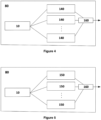
- the key point of this invention is to integrate the incoherent laser source into the pulse generation mechanism of the phase-OTDR system to make the system insensitive to the activities outside of the point of interest without decreasing the sensitivity at the point of interest.
- the present invention differs from the existing solutions with:
- the invention is a phase sensitive optical time domain reflectometry based distributed acoustic sensing system that eliminates the degradation in sensing performance encountered due to the finite extinction ratio of the optical elements.
- a coherent laser source (10) generates CW laser with narrow linewidth (smaller than 100 Hz) for detecting vibration sources near a sensing cable (70).
- the phase-OTDR systems are based on measuring the changes in phase of the returned Rayleigh scattering signal and this measurement is possible when the light injected into the sensing cable (70) is coherent.
- Sensing cable (70) is a telecommunications grade fiber optic cable or any other type of fiber optic cable that can be used for remote sensing applications.
- the first gain and filter block (20) amplifies and filters the laser in order to satisfy the power and coherency criteria of the light to be injected into the cable (70).
- the block (20) contains an optical amplifier/attenuator to adjust the power of the light to be injected into the cable (70). Optic power can be adjusted by using EDFA.
- the amplified signal is then filtered to remove undesired signal components that are due to the non-ideal behavior of the amplifier.
- Several different optical filter designs can be used in this block (20).
- the optic pulse generator (30) shapes the CW laser into the narrow optic pulses ( ⁇ 100 ns) with the desired pulse shape generated by RF signal pulse generator (40) for interrogation.
- the critical point in pulse generation is to obtain high extinction ratio, which is the ratio of the optic power within pulse (the ON state) and the optic power outside pulse (the OFF state).
- Optic pulse can be generated by using Acousto-optic Modulator (AOM) or Electro-optic Modulator (EOM) or any other optical component such as Kerr medium.
- AOM Acousto-optic Modulator
- EOM Electro-optic Modulator
- the shape of the optic pulse can vary based on the application, i.e. rectangular pulse, saw tooth pulse, etc.
- an incoherent laser source (80) generates CW laser with large linewidth for degrading the undesired coherent interference effect for the leakage light injected into the cable when optic pulse generator (30) is in OFF state.
- the incoherent laser source (80) can be constructed with:
- the second gain and filter block (90) amplifies/attenuates and filters the incoherent CW laser coming from the incoherent laser source (80) to satisfy the power and incoherency criteria.
- This part contains an optical amplifier/attenuator to adjust the power of the incoherent light injected into the sensing cable (70) such that its power is similar to the power of the coherent leakage light injected when the optic pulse generator (30) is in OFF state.
- Several different optical filter designs can be used in this block (90).
- This filter block should shape the frequency spectrum of the light injected into the sensing cable (70) such that the resulting incoherent light has a wide linewidth with a total power that is similar to the power of the coherent leakage light injected when the optic pulse generator (30) is in OFF state.
- gain and filter block (90) can be constructed as a combination of first gain and filter block (20) combined with optic pulse generator (30) and RF signal pulse generator (40), where RF signal pulse generator (40) is always in OFF state.
- the combiner (50) combines the optic signal coming from the optic pulse generator (30) and the second gain and filter block (90) and forwards the combined optic signal to a circulator (60).
- the circulator (60) injects the combined optic signal to the sensing cable (70) and forwards back reflected Rayleigh scattering signals coming from the sensing cable (70) to the third gain and filter block (100).
- the third gain and filter block (100) adjusts the power level of the returned Rayleigh backscattered signal and filters out the undesired frequency components in the returned Rayleigh backscattered signal for obtaining the best performance in the receiver block.
- the receiver block consists of a photo detector (110), an ADC (120) and a processor (130).
- the receiver block can be in the form of direct detection, heterodyne detection, homodyne detection or any other receiver format that can be used in distributed acoustic sensing applications.
- the photo detector (110) measures the optic power of the returned Rayleigh backscattered signal as an electrical signal (voltage or current).
- the photo detector block (110) may consist of a single photo detector or multiple photo detectors for measuring the returned Rayleigh backscattered optical signal based on the preferred embodiment.
- the ADC (120) digitizes the measured analog optic power to be processed by the processor (130). The single or multiple ADC (120) may be used for measuring based on the preferred embodiment.
- the optic pulse generation mechanism of the phase-OTDR architecture is modified and the receiver side is not changed as shown in Figure 3 .
- a second path is added into the transmitter side to change the characteristics of the optical pulse injected into the sensing cable (70) for interrogation.
- incoherent laser source (80) is used instead of the highly coherent one with the center frequency same as the coherent laser source (10) in the first path.
- the other optical and electronic parts may be kept identical to the first path.
- the optical signals generated at these two paths are combined by the combiner (50) and fed into the sensing cable (70).
- the AOM in the first path is driven by very narrow ( ⁇ 100 ns) electronic pulse with ON and OFF state and the AOM in the second path is driven continuously with OFF state. Therefore, while the first path generates optical pulse, the second path generates only the leakage optical signal with a much higher linewidth as compared to the optic signal in the first path.
- inserting incoherent laser signal g(t) to the normal phase-OTDR signal can be interpreted as contaminating the coherent leakage light with incoherent light. Since ⁇ ⁇ 1, the incoherent contamination does not alter the sensing performance of the system in the ON state of the optic pulse.
- the back reflected signal due to the leakage light injected into the fiber optic cable in the OFF state of the optic pulse.
- the OFF state while all the back reflected signals are almost the same frequency when g(t) does not exist, the back reflected signals are in random frequencies in a wide range when the g(t) is also injected.
- our proposed system architecture becomes an interrogation unit using optic pulse with two states, i.e., coherent ON state and incoherent OFF state.
- the coherent ON state is the desired optic signal that is highly sensitive to the small vibrations near or on the fiber optic cable.
- the incoherent OFF state is unavoidable and the undesired leakage signal due to the AOMs or EOMs with finite extinction ratio that is insensitive to the small vibrations near or on the fiber optic cable. Therefore, in the proposed system configuration, the small vibrations that are on the outside the area of the interrogating region with ON state of the optic pulse do not affect the sensing performance as compared to the fully coherent phase-OTDR system.
Landscapes
- Physics & Mathematics (AREA)
- General Physics & Mathematics (AREA)
- Measurement Of Mechanical Vibrations Or Ultrasonic Waves (AREA)
- Investigating Or Analysing Materials By Optical Means (AREA)
Claims (14)
- Phasenempfindliches, auf optischer Zeitbereichsreflektometrie basierendes verteiltes akustisches Abtastsystem, das die Verringerung einer Abtastleistung beseitigt, die auf das finite Extinktionsverhältnis der optischen Elemente zurückzuführen ist, das mit Folgendem versehen ist:• einem Sensorkabel (70), das für entfernte Abtastanwendungen verwendet wird,• einer kohärenten Laserquelle (10), die konfiguriert ist, um einen CW-Laser mit schmaler Linienbreite zu erzeugen, um Vibrationsquellen in der Nähe eines Sensorkabels (70) zu erfassen,• einem ersten Verstärkungs- und Filterblock (20), der konfiguriert ist, um den kohärenten CW-Laser zu verstärken, um die Leistung anzupassen, und den in das Kabel einzuspeisenden Laser zu filtern, um mögliche unerwünschte Frequenzkomponenten zu beseitigen, die während einer Leistungsanpassung eingeführt werden,• einem optischen Impulsgenerator (30), der konfiguriert ist, um den CW-Laser in die schmalen optischen Impulse mit der gewünschten Impulsform zu formen, die von dem HF-Signalimpulsgenerator (40) erzeugt wird,• einem Zirkulator (60), der konfiguriert ist, um das optische Signal in das Sensorkabel (70) einzuspeisen und die von dem Kabel stammenden reflektierten Rayleigh-Streusignale an den dritten Verstärkungs- und Filterblock (100) weiterzuleiten,• wobei der dritte Verstärkungs- und Filterblock (100) konfiguriert ist, um den Leistungspegel des Signals anzupassen und die unerwünschten Frequenzkomponenten des zurückgestreuten Rayleigh-Signals herauszufiltern,• einem Empfängerblock, der konfiguriert ist, um die optische Leistung des zurückgestreuten Rayleigh-Signals zu messen, die gemessene analoge optische Leistung zu digitalisieren und die digitalisierte optische Signalleistung zu verarbeiten,
wobei das System ist dadurch gekennzeichnet, dass es Folgendes umfasst;• eine inkohärente Laserquelle (80), die konfiguriert ist, um einen CW-Laser mit großer Linienbreite zu erzeugen, um den Kohärenzinterferenzeffekt oder die Kohärenzlänge für das in das Kabel eingespeiste Licht zu verringern, wenn der optische Impulsgenerator (30) in einem AUS-Zustand ist,• einen zweiten Verstärkungs- und Filterblock (90), der konfiguriert ist, um die Leistung des inkohärenten Lichts anzupassen und zu filtern, sodass das resultierende inkohärente Licht eine große Linienbreite aufweist und seine Leistung der Leistung des kohärenten Streulichts ähnlich ist, das eingespeist wird, wenn der optische Impulsgenerator (30) in einem AUS-Zustand ist,• einen Kombinierer (50), der konfiguriert ist, um das von dem optischen Impulsgenerator (30) und dem zweiten Verstärkungs- und Filterblock (90) stammende optische Signal zu kombinieren und das kombinierte optische Signal an den Zirkulator (60) weiterzuleiten. - System nach Anspruch 1, wobei der in das Lichtwellenleiterkabel eingespeiste optische Impuls p(t) wie folgt dargestellt werden kann
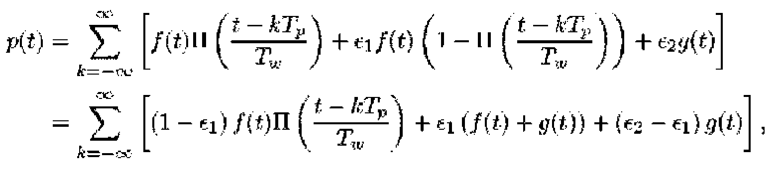

- System nach Anspruch 2, wobei das eingespeiste optische Signal p(t) vereinfacht werden kann als

- System nach Anspruch 1, wobei der optische Impulsgenerator (30) ein akusto-optischer Modulator oder ein elektro-optischer Modulator oder ein Kerr-Medium ist.
- System nach Anspruch 1, wobei die optische Leistung durch Verwendung von Erbiumdotierten Faserverstärkern in Verstärkungs- und Filterblöcken (20, 90, 100) angepasst wird.
- System nach Anspruch 1, wobei der Empfängerblock aus einem Fotodetektor (110), der die optische Leistung misst, einem Analog-Digital-Wandler (120) und einem Prozessor (130), der die digitalisierte optische Signalleistung verarbeitet, besteht.
- System nach Anspruch 1 oder 6, umfassend einen Fotodetektorblock, der aus einem einzelnen Fotodetektor (110) oder mehreren Fotodetektoren (110) zum Messen des zurückgestreuten optischen Rayleigh-Signals besteht.
- System nach Anspruch 1, wobei der Empfängerblock die Form von direkter Erfassung, Heterodyn-Erfassung, Homodyn-Erfassung oder eines anderen Empfängerformats ist, das bei verteilter akustischer Abtastung verwendet werden kann.
- System nach Anspruch 1, wobei die inkohärente Laserquelle (80) eine Kombination mehrerer CW-Laser mit schmaler Linienbreite ist, die mit optischen Frequenzschiebern (140) verschoben werden.
- System nach Anspruch 1, wobei die inkohärente Laserquelle (80) eine Kombination mehrerer CW-Laser mit schmaler Linienbreite ist, die mit optischen Phasenschiebern (150) verschoben werden.
- System nach Anspruch 9 oder 10, wobei die Frequenz-/Phasenschieber (140, 150) die Laserfrequenz / Phase mit einem festen Wert oder einem mit einer externen Signalquelle veränderten Verschiebungswert verschieben.
- System nach Anspruch 1, wobei das Sensorkabel (70) ein Lichtwellenleiterkabel ist.
- System nach Anspruch 1, wobei der zweite Verstärkungs- und Filterblock (90) mit dem ersten Verstärkungs- und Filterblock (20) in Kombination mit einem optischen Impulsgenerator (30) und einem Signalimpulsgenerator (40) realisiert ist, wobei der Signalimpulsgenerator (40) immer in einem AUS-Zustand ist.
- Phasenempfindliches, auf optischer Zeitbereichsreflektometrie basierendes verteiltes akustisches Abtastverfahren, das die Verringerung einer Abtastleistung beseitigt, die auf das finite Extinktionsverhältnis der optischen Elemente zurückzuführen ist, umfassend die folgenden Verarbeitungsschritte;• Erzeugen eines CW-Lasers mit schmaler Linienbreite durch eine kohärente Laserquelle zur Erfassung von Vibrationsquellen in der Nähe eines Lichtwellenleiterkabels,• Anpassen der Leistung des CW-Lasers und Filtern zur Beseitigung möglicher unerwünschter Frequenzkomponenten, die bei einer Leistungsanpassung eingeführt werden,• Formen des CW-Lasers in schmale optische Impulse durch einen optischen Impulsgenerator mit der gewünschten Impulsform,• Erzeugen eines CW-Lasers mit großer Linienbreite durch eine inkohärente Laserquelle zum Verringern des Kohärenz-Interferenz-Effekts oder der Kohärenzlänge für das in das Kabel eingespeiste Licht, wenn der optische Impulsgenerator in einem AUS-Zustand ist,• Anpassen der Leistung des inkohärenten Lichts und Filtern, sodass das resultierende inkohärente Licht eine große Linienbreite aufweist und seine Leistung der Leistung des kohärenten Streulichts ähnlich ist, das eingespeist wird, wenn der optische Impulsgenerator in einem AUS-Zustand ist,• Kombinieren der von den optischen Pfaden stammenden optischen Signale mit einem Kombinierer und Weiterleiten des kombinierten optischen Signals an einen Zirkulator,• Einspeisen des optischen Signals in das Kabel und Weiterleiten der von dem Kabel reflektierten Rayleigh-Streusignale an einen Verstärkungs- und Filterblock,• Anpassen des Leistungspegels des Signals und Herausfiltern der unerwünschten Frequenzkomponenten aus dem zurückgestreuten Rayleigh-Signal,• Messen der optischen Leistung des zurückgestreuten Rayleigh-Signals,• Digitalisieren der gemessenen analogen optischen Leistung und Verarbeiten der digitalisierten optischen Signalleistung.
Applications Claiming Priority (1)
| Application Number | Priority Date | Filing Date | Title |
|---|---|---|---|
| PCT/TR2018/050423 WO2020032878A1 (en) | 2018-08-08 | 2018-08-08 | Extinction ratio free phase sensitive optical time domain reflectometry based distributed acoustic sensing system |
Publications (2)
| Publication Number | Publication Date |
|---|---|
| EP3833943A1 EP3833943A1 (de) | 2021-06-16 |
| EP3833943B1 true EP3833943B1 (de) | 2023-10-04 |
Family
ID=66240187
Family Applications (1)
| Application Number | Title | Priority Date | Filing Date |
|---|---|---|---|
| EP18869466.5A Active EP3833943B1 (de) | 2018-08-08 | 2018-08-08 | Auf extinktionsverhältnisfreiem phasenempfindlichem optischem zeitbereichsreflektometer basierendes verteiltes schallerfassungssystem |
Country Status (4)
| Country | Link |
|---|---|
| US (1) | US11959799B2 (de) |
| EP (1) | EP3833943B1 (de) |
| CA (1) | CA3104086C (de) |
| WO (1) | WO2020032878A1 (de) |
Families Citing this family (15)
| Publication number | Priority date | Publication date | Assignee | Title |
|---|---|---|---|---|
| US11681042B2 (en) * | 2020-04-07 | 2023-06-20 | Nec Corporation | Sparse excitation method for 3-dimensional underground cable localization by fiber optic sensing |
| CN111912513B (zh) * | 2020-07-14 | 2022-03-22 | 国家电网有限公司 | 一种基于φ-otdr的光缆沿线挖掘机施工事件的识别方法 |
| CN112504430B (zh) * | 2020-11-26 | 2022-03-01 | 南京大学 | 一种基于振动敏感型光纤传感技术的杆塔结构健康监测的方法 |
| CN113418539B (zh) * | 2021-06-21 | 2022-03-25 | 南京大学 | 具有自由多空间分辨率的自外差式的φ-OTDR系统 |
| US12078528B2 (en) * | 2021-07-22 | 2024-09-03 | Nec Corporation | Fiber sensing using supervisory path of submarine cables |
| CN116707628A (zh) * | 2022-02-24 | 2023-09-05 | 华为技术有限公司 | 一种传输信号的方法和装置 |
| CN114543851B (zh) * | 2022-02-28 | 2024-06-21 | 宁夏回族自治区水利工程建设中心 | 提高信噪比与细节特征的相敏光时域反射仪信号调理方法 |
| CN114719955B (zh) * | 2022-04-15 | 2023-04-07 | 北京理工大学 | 光频域反射仪分布式光纤测量中的相干衰落噪声抑制方法 |
| US20240012167A1 (en) * | 2022-07-05 | 2024-01-11 | Exfo Inc. | Method and apparatus of distributed acoustic sensing |
| CN115452011B (zh) * | 2022-08-02 | 2025-09-30 | 南方科技大学 | 用于相敏光时域反射仪的探测数据存储、读取方法及系统 |
| CN116295782B (zh) * | 2023-03-08 | 2023-10-03 | 浙江信测通信股份有限公司 | 一种基于φ-otdr的分布式光纤振动传感系统及相位解调方法 |
| CN116338388A (zh) * | 2023-03-15 | 2023-06-27 | 南京大学 | 基于高频率响应das系统的变压器局部放电监测方法 |
| CN117590300A (zh) * | 2023-11-21 | 2024-02-23 | 兰州大学 | 基于分布式光纤声波传感的超导磁体失超检测系统及方法 |
| CN118464093B (zh) * | 2024-05-14 | 2026-04-21 | 北京理工大学 | 多芯光纤的抗衰落光频域反射分布式测量方法及装置 |
| CN118623997A (zh) * | 2024-07-03 | 2024-09-10 | 南京大学 | 一种基于光子集成的长距离宽频响分布式光纤声波传感系统及方法 |
Family Cites Families (12)
| Publication number | Priority date | Publication date | Assignee | Title |
|---|---|---|---|---|
| GB2442745B (en) | 2006-10-13 | 2011-04-06 | At & T Corp | Method and apparatus for acoustic sensing using multiple optical pulses |
| GB2469709B (en) * | 2009-02-17 | 2013-09-25 | Schlumberger Holdings | Optical monitoring of fluid flow |
| GB2517614B (en) * | 2009-05-27 | 2015-06-24 | Silixa Ltd | Fibre arrangement for distributed acoustic sensing |
| GB0917150D0 (en) * | 2009-09-30 | 2009-11-11 | Qinetiq Ltd | Phase based sensing |
| US10309825B2 (en) * | 2015-04-07 | 2019-06-04 | Halliburton Energy Services, Inc. | Reducing noise in a distributed acoustic sensing system downhole |
| WO2017069724A1 (en) | 2015-10-19 | 2017-04-27 | Halliburton Energy Service, Inc. | Distributed acoustic sensing systems and methods employing multiple pulse widths |
| US11002594B2 (en) * | 2015-11-20 | 2021-05-11 | Sentek Instrument, Llc | Method and apparatus for distributed sensing |
| US10345138B2 (en) | 2016-01-22 | 2019-07-09 | Nec Corporation | Method to increase the signal to noise ratio of distributed acoustic sensing by spatial averaging |
| US10466172B2 (en) | 2016-08-22 | 2019-11-05 | Nec Corporation | Distributed acoustic sensing in a multimode optical fiber using distributed mode coupling and delay |
| CN106961069B (zh) | 2017-04-25 | 2019-02-01 | 电子科技大学 | 基于反馈结构的高消光比周期脉冲信号产生系统及方法 |
| CN107144339A (zh) | 2017-05-17 | 2017-09-08 | 长沙理工大学 | 一种基于调制脉冲技术的分布式光纤传感系统 |
| JP6989703B2 (ja) * | 2017-07-26 | 2022-01-05 | テッラ15 プロプライエタリー リミテッド | 分布光学センシングシステム及び方法 |
-
2018
- 2018-08-08 EP EP18869466.5A patent/EP3833943B1/de active Active
- 2018-08-08 US US17/259,686 patent/US11959799B2/en active Active
- 2018-08-08 CA CA3104086A patent/CA3104086C/en active Active
- 2018-08-08 WO PCT/TR2018/050423 patent/WO2020032878A1/en not_active Ceased
Also Published As
| Publication number | Publication date |
|---|---|
| CA3104086C (en) | 2023-08-01 |
| CA3104086A1 (en) | 2020-02-13 |
| US11959799B2 (en) | 2024-04-16 |
| EP3833943A1 (de) | 2021-06-16 |
| RU2768226C1 (ru) | 2022-03-23 |
| US20210140814A1 (en) | 2021-05-13 |
| WO2020032878A1 (en) | 2020-02-13 |
Similar Documents
| Publication | Publication Date | Title |
|---|---|---|
| EP3833943B1 (de) | Auf extinktionsverhältnisfreiem phasenempfindlichem optischem zeitbereichsreflektometer basierendes verteiltes schallerfassungssystem | |
| EP2084505B1 (de) | Detektieren einer störung in der phase von sich in einem optischen wellenleiter ausbreitendem licht | |
| CN111373613B (zh) | 用于纤维感测的定制分布式放大 | |
| EP0944813B1 (de) | Verteilte spannung- und temperaturmesssystem | |
| KR100930342B1 (ko) | 분포 광섬유 센서 시스템 | |
| US11320302B2 (en) | High-rate distributed acoustic sensing using high-power light pulses | |
| JP5322184B2 (ja) | 分布型光ファイバセンサ | |
| JP5322162B2 (ja) | 分布型光ファイバ圧力センサ | |
| CN103597328B (zh) | 一种用于传感的传感器和方法 | |
| EP1338876A2 (de) | Optische Reflexionsmessung im Zeitbereich | |
| CA2247293A1 (en) | Distributed sensing apparatus | |
| US12345585B2 (en) | Few-mode Rayleigh-based distributed fiber sensor for simultaneous temperature and strain sensing | |
| WO2004102840A1 (en) | Optic communication or transmission media sensing | |
| KR20180010049A (ko) | 유효 측정점 개수가 확대된 공간선택적 브릴루앙 분포형 광섬유 센서 및 브릴루앙 산란을 이용한 센싱 방법 | |
| CA2615327C (en) | Optical fiber characteristic measuring system | |
| Liu et al. | Monitoring distance enhancement with chaotic laser for OTDR system | |
| Peng et al. | 106km fully-distributed fiber-optic fence based on P-OTDR with 2nd-order Raman amplification | |
| RU2768226C9 (ru) | Система распределенного акустического зондирования, основанная на фазочувствительной оптической рефлектометрии во временной области без влияния коэффициента ослабления | |
| Sandah et al. | Spectral Shadowing Compensation in Double-pulse FBG-assisted φ-OTDR | |
| CN116707628A (zh) | 一种传输信号的方法和装置 | |
| CN117092715A (zh) | 光纤传感系统和检测方法 | |
| KR102644918B1 (ko) | 감도 향상형 광섬유 음향 분포센서 | |
| Mu et al. | Laser-Frequency-Drift Compensation in Φ-OTDR Using Linear Fitting Intercepts Method | |
| Aktas et al. | A model-based analysis of extinction ratio effects on phase-OTDR distributed acoustic sensing system performance | |
| Ryu et al. | 50 km range BOCDA assisted by Raman amplification |
Legal Events
| Date | Code | Title | Description |
|---|---|---|---|
| STAA | Information on the status of an ep patent application or granted ep patent |
Free format text: STATUS: UNKNOWN |
|
| STAA | Information on the status of an ep patent application or granted ep patent |
Free format text: STATUS: THE INTERNATIONAL PUBLICATION HAS BEEN MADE |
|
| PUAI | Public reference made under article 153(3) epc to a published international application that has entered the european phase |
Free format text: ORIGINAL CODE: 0009012 |
|
| STAA | Information on the status of an ep patent application or granted ep patent |
Free format text: STATUS: REQUEST FOR EXAMINATION WAS MADE |
|
| 17P | Request for examination filed |
Effective date: 20210212 |
|
| AK | Designated contracting states |
Kind code of ref document: A1 Designated state(s): AL AT BE BG CH CY CZ DE DK EE ES FI FR GB GR HR HU IE IS IT LI LT LU LV MC MK MT NL NO PL PT RO RS SE SI SK SM TR |
|
| DAV | Request for validation of the european patent (deleted) | ||
| DAX | Request for extension of the european patent (deleted) | ||
| GRAP | Despatch of communication of intention to grant a patent |
Free format text: ORIGINAL CODE: EPIDOSNIGR1 |
|
| STAA | Information on the status of an ep patent application or granted ep patent |
Free format text: STATUS: GRANT OF PATENT IS INTENDED |
|
| INTG | Intention to grant announced |
Effective date: 20230504 |
|
| P01 | Opt-out of the competence of the unified patent court (upc) registered |
Effective date: 20230529 |
|
| GRAS | Grant fee paid |
Free format text: ORIGINAL CODE: EPIDOSNIGR3 |
|
| GRAA | (expected) grant |
Free format text: ORIGINAL CODE: 0009210 |
|
| STAA | Information on the status of an ep patent application or granted ep patent |
Free format text: STATUS: THE PATENT HAS BEEN GRANTED |
|
| AK | Designated contracting states |
Kind code of ref document: B1 Designated state(s): AL AT BE BG CH CY CZ DE DK EE ES FI FR GB GR HR HU IE IS IT LI LT LU LV MC MK MT NL NO PL PT RO RS SE SI SK SM TR |
|
| REG | Reference to a national code |
Ref country code: GB Ref legal event code: FG4D |
|
| REG | Reference to a national code |
Ref country code: CH Ref legal event code: EP |
|
| REG | Reference to a national code |
Ref country code: DE Ref legal event code: R096 Ref document number: 602018058900 Country of ref document: DE |
|
| REG | Reference to a national code |
Ref country code: IE Ref legal event code: FG4D |
|
| REG | Reference to a national code |
Ref country code: LT Ref legal event code: MG9D |
|
| REG | Reference to a national code |
Ref country code: NL Ref legal event code: MP Effective date: 20231004 |
|
| PG25 | Lapsed in a contracting state [announced via postgrant information from national office to epo] |
Ref country code: NL Free format text: LAPSE BECAUSE OF FAILURE TO SUBMIT A TRANSLATION OF THE DESCRIPTION OR TO PAY THE FEE WITHIN THE PRESCRIBED TIME-LIMIT Effective date: 20231004 |
|
| PG25 | Lapsed in a contracting state [announced via postgrant information from national office to epo] |
Ref country code: GR Free format text: LAPSE BECAUSE OF FAILURE TO SUBMIT A TRANSLATION OF THE DESCRIPTION OR TO PAY THE FEE WITHIN THE PRESCRIBED TIME-LIMIT Effective date: 20240105 |
|
| PG25 | Lapsed in a contracting state [announced via postgrant information from national office to epo] |
Ref country code: IS Free format text: LAPSE BECAUSE OF FAILURE TO SUBMIT A TRANSLATION OF THE DESCRIPTION OR TO PAY THE FEE WITHIN THE PRESCRIBED TIME-LIMIT Effective date: 20240204 |
|
| PG25 | Lapsed in a contracting state [announced via postgrant information from national office to epo] |
Ref country code: LT Free format text: LAPSE BECAUSE OF FAILURE TO SUBMIT A TRANSLATION OF THE DESCRIPTION OR TO PAY THE FEE WITHIN THE PRESCRIBED TIME-LIMIT Effective date: 20231004 |
|
| REG | Reference to a national code |
Ref country code: AT Ref legal event code: UEP Ref document number: 1618172 Country of ref document: AT Kind code of ref document: T Effective date: 20231004 |
|
| PG25 | Lapsed in a contracting state [announced via postgrant information from national office to epo] |
Ref country code: ES Free format text: LAPSE BECAUSE OF FAILURE TO SUBMIT A TRANSLATION OF THE DESCRIPTION OR TO PAY THE FEE WITHIN THE PRESCRIBED TIME-LIMIT Effective date: 20231004 |
|
| PG25 | Lapsed in a contracting state [announced via postgrant information from national office to epo] |
Ref country code: LT Free format text: LAPSE BECAUSE OF FAILURE TO SUBMIT A TRANSLATION OF THE DESCRIPTION OR TO PAY THE FEE WITHIN THE PRESCRIBED TIME-LIMIT Effective date: 20231004 Ref country code: IS Free format text: LAPSE BECAUSE OF FAILURE TO SUBMIT A TRANSLATION OF THE DESCRIPTION OR TO PAY THE FEE WITHIN THE PRESCRIBED TIME-LIMIT Effective date: 20240204 Ref country code: GR Free format text: LAPSE BECAUSE OF FAILURE TO SUBMIT A TRANSLATION OF THE DESCRIPTION OR TO PAY THE FEE WITHIN THE PRESCRIBED TIME-LIMIT Effective date: 20240105 Ref country code: ES Free format text: LAPSE BECAUSE OF FAILURE TO SUBMIT A TRANSLATION OF THE DESCRIPTION OR TO PAY THE FEE WITHIN THE PRESCRIBED TIME-LIMIT Effective date: 20231004 Ref country code: BG Free format text: LAPSE BECAUSE OF FAILURE TO SUBMIT A TRANSLATION OF THE DESCRIPTION OR TO PAY THE FEE WITHIN THE PRESCRIBED TIME-LIMIT Effective date: 20240104 Ref country code: PT Free format text: LAPSE BECAUSE OF FAILURE TO SUBMIT A TRANSLATION OF THE DESCRIPTION OR TO PAY THE FEE WITHIN THE PRESCRIBED TIME-LIMIT Effective date: 20240205 |
|
| PG25 | Lapsed in a contracting state [announced via postgrant information from national office to epo] |
Ref country code: SE Free format text: LAPSE BECAUSE OF FAILURE TO SUBMIT A TRANSLATION OF THE DESCRIPTION OR TO PAY THE FEE WITHIN THE PRESCRIBED TIME-LIMIT Effective date: 20231004 Ref country code: RS Free format text: LAPSE BECAUSE OF FAILURE TO SUBMIT A TRANSLATION OF THE DESCRIPTION OR TO PAY THE FEE WITHIN THE PRESCRIBED TIME-LIMIT Effective date: 20231004 Ref country code: PL Free format text: LAPSE BECAUSE OF FAILURE TO SUBMIT A TRANSLATION OF THE DESCRIPTION OR TO PAY THE FEE WITHIN THE PRESCRIBED TIME-LIMIT Effective date: 20231004 Ref country code: NO Free format text: LAPSE BECAUSE OF FAILURE TO SUBMIT A TRANSLATION OF THE DESCRIPTION OR TO PAY THE FEE WITHIN THE PRESCRIBED TIME-LIMIT Effective date: 20240104 Ref country code: LV Free format text: LAPSE BECAUSE OF FAILURE TO SUBMIT A TRANSLATION OF THE DESCRIPTION OR TO PAY THE FEE WITHIN THE PRESCRIBED TIME-LIMIT Effective date: 20231004 Ref country code: HR Free format text: LAPSE BECAUSE OF FAILURE TO SUBMIT A TRANSLATION OF THE DESCRIPTION OR TO PAY THE FEE WITHIN THE PRESCRIBED TIME-LIMIT Effective date: 20231004 |
|
| REG | Reference to a national code |
Ref country code: DE Ref legal event code: R097 Ref document number: 602018058900 Country of ref document: DE |
|
| PG25 | Lapsed in a contracting state [announced via postgrant information from national office to epo] |
Ref country code: DK Free format text: LAPSE BECAUSE OF FAILURE TO SUBMIT A TRANSLATION OF THE DESCRIPTION OR TO PAY THE FEE WITHIN THE PRESCRIBED TIME-LIMIT Effective date: 20231004 |
|
| PG25 | Lapsed in a contracting state [announced via postgrant information from national office to epo] |
Ref country code: CZ Free format text: LAPSE BECAUSE OF FAILURE TO SUBMIT A TRANSLATION OF THE DESCRIPTION OR TO PAY THE FEE WITHIN THE PRESCRIBED TIME-LIMIT Effective date: 20231004 |
|
| PG25 | Lapsed in a contracting state [announced via postgrant information from national office to epo] |
Ref country code: SK Free format text: LAPSE BECAUSE OF FAILURE TO SUBMIT A TRANSLATION OF THE DESCRIPTION OR TO PAY THE FEE WITHIN THE PRESCRIBED TIME-LIMIT Effective date: 20231004 |
|
| PG25 | Lapsed in a contracting state [announced via postgrant information from national office to epo] |
Ref country code: SM Free format text: LAPSE BECAUSE OF FAILURE TO SUBMIT A TRANSLATION OF THE DESCRIPTION OR TO PAY THE FEE WITHIN THE PRESCRIBED TIME-LIMIT Effective date: 20231004 Ref country code: SK Free format text: LAPSE BECAUSE OF FAILURE TO SUBMIT A TRANSLATION OF THE DESCRIPTION OR TO PAY THE FEE WITHIN THE PRESCRIBED TIME-LIMIT Effective date: 20231004 Ref country code: RO Free format text: LAPSE BECAUSE OF FAILURE TO SUBMIT A TRANSLATION OF THE DESCRIPTION OR TO PAY THE FEE WITHIN THE PRESCRIBED TIME-LIMIT Effective date: 20231004 Ref country code: IT Free format text: LAPSE BECAUSE OF FAILURE TO SUBMIT A TRANSLATION OF THE DESCRIPTION OR TO PAY THE FEE WITHIN THE PRESCRIBED TIME-LIMIT Effective date: 20231004 Ref country code: EE Free format text: LAPSE BECAUSE OF FAILURE TO SUBMIT A TRANSLATION OF THE DESCRIPTION OR TO PAY THE FEE WITHIN THE PRESCRIBED TIME-LIMIT Effective date: 20231004 Ref country code: DK Free format text: LAPSE BECAUSE OF FAILURE TO SUBMIT A TRANSLATION OF THE DESCRIPTION OR TO PAY THE FEE WITHIN THE PRESCRIBED TIME-LIMIT Effective date: 20231004 Ref country code: CZ Free format text: LAPSE BECAUSE OF FAILURE TO SUBMIT A TRANSLATION OF THE DESCRIPTION OR TO PAY THE FEE WITHIN THE PRESCRIBED TIME-LIMIT Effective date: 20231004 |
|
| PLBE | No opposition filed within time limit |
Free format text: ORIGINAL CODE: 0009261 |
|
| STAA | Information on the status of an ep patent application or granted ep patent |
Free format text: STATUS: NO OPPOSITION FILED WITHIN TIME LIMIT |
|
| 26N | No opposition filed |
Effective date: 20240705 |
|
| PG25 | Lapsed in a contracting state [announced via postgrant information from national office to epo] |
Ref country code: SI Free format text: LAPSE BECAUSE OF FAILURE TO SUBMIT A TRANSLATION OF THE DESCRIPTION OR TO PAY THE FEE WITHIN THE PRESCRIBED TIME-LIMIT Effective date: 20231004 |
|
| PG25 | Lapsed in a contracting state [announced via postgrant information from national office to epo] |
Ref country code: SI Free format text: LAPSE BECAUSE OF FAILURE TO SUBMIT A TRANSLATION OF THE DESCRIPTION OR TO PAY THE FEE WITHIN THE PRESCRIBED TIME-LIMIT Effective date: 20231004 |
|
| REG | Reference to a national code |
Ref country code: CH Ref legal event code: PL |
|
| PG25 | Lapsed in a contracting state [announced via postgrant information from national office to epo] |
Ref country code: LU Free format text: LAPSE BECAUSE OF NON-PAYMENT OF DUE FEES Effective date: 20240808 |
|
| PG25 | Lapsed in a contracting state [announced via postgrant information from national office to epo] |
Ref country code: MC Free format text: LAPSE BECAUSE OF FAILURE TO SUBMIT A TRANSLATION OF THE DESCRIPTION OR TO PAY THE FEE WITHIN THE PRESCRIBED TIME-LIMIT Effective date: 20231004 Ref country code: CH Free format text: LAPSE BECAUSE OF NON-PAYMENT OF DUE FEES Effective date: 20240831 |
|
| REG | Reference to a national code |
Ref country code: BE Ref legal event code: MM Effective date: 20240831 |
|
| PG25 | Lapsed in a contracting state [announced via postgrant information from national office to epo] |
Ref country code: BE Free format text: LAPSE BECAUSE OF NON-PAYMENT OF DUE FEES Effective date: 20240831 |
|
| PG25 | Lapsed in a contracting state [announced via postgrant information from national office to epo] |
Ref country code: FR Free format text: LAPSE BECAUSE OF NON-PAYMENT OF DUE FEES Effective date: 20240831 |
|
| PG25 | Lapsed in a contracting state [announced via postgrant information from national office to epo] |
Ref country code: IE Free format text: LAPSE BECAUSE OF NON-PAYMENT OF DUE FEES Effective date: 20240808 |
|
| PG25 | Lapsed in a contracting state [announced via postgrant information from national office to epo] |
Ref country code: FI Free format text: LAPSE BECAUSE OF FAILURE TO SUBMIT A TRANSLATION OF THE DESCRIPTION OR TO PAY THE FEE WITHIN THE PRESCRIBED TIME-LIMIT Effective date: 20231004 |
|
| PGFP | Annual fee paid to national office [announced via postgrant information from national office to epo] |
Ref country code: DE Payment date: 20250828 Year of fee payment: 8 |
|
| PGFP | Annual fee paid to national office [announced via postgrant information from national office to epo] |
Ref country code: TR Payment date: 20250711 Year of fee payment: 8 |
|
| PGFP | Annual fee paid to national office [announced via postgrant information from national office to epo] |
Ref country code: GB Payment date: 20250729 Year of fee payment: 8 |
|
| PGFP | Annual fee paid to national office [announced via postgrant information from national office to epo] |
Ref country code: AT Payment date: 20250826 Year of fee payment: 8 |
|
| PG25 | Lapsed in a contracting state [announced via postgrant information from national office to epo] |
Ref country code: CY Free format text: LAPSE BECAUSE OF FAILURE TO SUBMIT A TRANSLATION OF THE DESCRIPTION OR TO PAY THE FEE WITHIN THE PRESCRIBED TIME-LIMIT; INVALID AB INITIO Effective date: 20180808 |
|
| PG25 | Lapsed in a contracting state [announced via postgrant information from national office to epo] |
Ref country code: HU Free format text: LAPSE BECAUSE OF FAILURE TO SUBMIT A TRANSLATION OF THE DESCRIPTION OR TO PAY THE FEE WITHIN THE PRESCRIBED TIME-LIMIT; INVALID AB INITIO Effective date: 20180808 |