EP3833943B1 - Extinction ratio free phase sensitive optical time domain reflectometry based distributed acoustic sensing system - Google Patents
Extinction ratio free phase sensitive optical time domain reflectometry based distributed acoustic sensing system Download PDFInfo
- Publication number
- EP3833943B1 EP3833943B1 EP18869466.5A EP18869466A EP3833943B1 EP 3833943 B1 EP3833943 B1 EP 3833943B1 EP 18869466 A EP18869466 A EP 18869466A EP 3833943 B1 EP3833943 B1 EP 3833943B1
- Authority
- EP
- European Patent Office
- Prior art keywords
- optic
- signal
- power
- cable
- laser
- Prior art date
- Legal status (The legal status is an assumption and is not a legal conclusion. Google has not performed a legal analysis and makes no representation as to the accuracy of the status listed.)
- Active
Links
- 238000000253 optical time-domain reflectometry Methods 0.000 title claims description 51
- 230000008033 biological extinction Effects 0.000 title claims description 30
- 239000000835 fiber Substances 0.000 claims description 53
- 230000003287 optical effect Effects 0.000 claims description 50
- 230000001427 coherent effect Effects 0.000 claims description 27
- 230000000694 effects Effects 0.000 claims description 11
- 238000000034 method Methods 0.000 claims description 9
- 238000001514 detection method Methods 0.000 claims description 8
- 230000015556 catabolic process Effects 0.000 claims description 6
- 238000006731 degradation reaction Methods 0.000 claims description 6
- 230000000593 degrading effect Effects 0.000 claims description 4
- 238000012545 processing Methods 0.000 claims description 4
- 229910052691 Erbium Inorganic materials 0.000 claims description 2
- UYAHIZSMUZPPFV-UHFFFAOYSA-N erbium Chemical compound [Er] UYAHIZSMUZPPFV-UHFFFAOYSA-N 0.000 claims description 2
- 238000001914 filtration Methods 0.000 claims 6
- 238000007493 shaping process Methods 0.000 claims 1
- 238000013461 design Methods 0.000 description 8
- 230000007246 mechanism Effects 0.000 description 8
- 239000013307 optical fiber Substances 0.000 description 7
- 230000008859 change Effects 0.000 description 6
- 238000005259 measurement Methods 0.000 description 6
- 230000010363 phase shift Effects 0.000 description 5
- 230000004048 modification Effects 0.000 description 3
- 230000008569 process Effects 0.000 description 3
- 230000035945 sensitivity Effects 0.000 description 3
- 238000010586 diagram Methods 0.000 description 2
- 230000002452 interceptive effect Effects 0.000 description 2
- 238000012986 modification Methods 0.000 description 2
- 238000012544 monitoring process Methods 0.000 description 2
- 230000000737 periodic effect Effects 0.000 description 2
- 238000012935 Averaging Methods 0.000 description 1
- 230000005374 Kerr effect Effects 0.000 description 1
- 230000004075 alteration Effects 0.000 description 1
- 238000013459 approach Methods 0.000 description 1
- 230000006399 behavior Effects 0.000 description 1
- 230000005540 biological transmission Effects 0.000 description 1
- 239000000969 carrier Substances 0.000 description 1
- 238000011109 contamination Methods 0.000 description 1
- 230000001186 cumulative effect Effects 0.000 description 1
- 230000003247 decreasing effect Effects 0.000 description 1
- 230000003111 delayed effect Effects 0.000 description 1
- 230000001419 dependent effect Effects 0.000 description 1
- 230000005670 electromagnetic radiation Effects 0.000 description 1
- 238000005516 engineering process Methods 0.000 description 1
- 230000007613 environmental effect Effects 0.000 description 1
- 238000011156 evaluation Methods 0.000 description 1
- 238000005562 fading Methods 0.000 description 1
- 230000000670 limiting effect Effects 0.000 description 1
- 238000004519 manufacturing process Methods 0.000 description 1
- 230000036961 partial effect Effects 0.000 description 1
- 230000037081 physical activity Effects 0.000 description 1
- 230000001902 propagating effect Effects 0.000 description 1
- 230000002829 reductive effect Effects 0.000 description 1
- 230000004044 response Effects 0.000 description 1
- 238000001228 spectrum Methods 0.000 description 1
- 230000002123 temporal effect Effects 0.000 description 1
Images

Classifications
-
- G—PHYSICS
- G01—MEASURING; TESTING
- G01H—MEASUREMENT OF MECHANICAL VIBRATIONS OR ULTRASONIC, SONIC OR INFRASONIC WAVES
- G01H9/00—Measuring mechanical vibrations or ultrasonic, sonic or infrasonic waves by using radiation-sensitive means, e.g. optical means
- G01H9/004—Measuring mechanical vibrations or ultrasonic, sonic or infrasonic waves by using radiation-sensitive means, e.g. optical means using fibre optic sensors
- G01H9/006—Measuring mechanical vibrations or ultrasonic, sonic or infrasonic waves by using radiation-sensitive means, e.g. optical means using fibre optic sensors the vibrations causing a variation in the relative position of the end of a fibre and another element
-
- G—PHYSICS
- G01—MEASURING; TESTING
- G01H—MEASUREMENT OF MECHANICAL VIBRATIONS OR ULTRASONIC, SONIC OR INFRASONIC WAVES
- G01H9/00—Measuring mechanical vibrations or ultrasonic, sonic or infrasonic waves by using radiation-sensitive means, e.g. optical means
-
- G—PHYSICS
- G01—MEASURING; TESTING
- G01D—MEASURING NOT SPECIALLY ADAPTED FOR A SPECIFIC VARIABLE; ARRANGEMENTS FOR MEASURING TWO OR MORE VARIABLES NOT COVERED IN A SINGLE OTHER SUBCLASS; TARIFF METERING APPARATUS; MEASURING OR TESTING NOT OTHERWISE PROVIDED FOR
- G01D5/00—Mechanical means for transferring the output of a sensing member; Means for converting the output of a sensing member to another variable where the form or nature of the sensing member does not constrain the means for converting; Transducers not specially adapted for a specific variable
- G01D5/26—Mechanical means for transferring the output of a sensing member; Means for converting the output of a sensing member to another variable where the form or nature of the sensing member does not constrain the means for converting; Transducers not specially adapted for a specific variable characterised by optical transfer means, i.e. using infrared, visible, or ultraviolet light
- G01D5/32—Mechanical means for transferring the output of a sensing member; Means for converting the output of a sensing member to another variable where the form or nature of the sensing member does not constrain the means for converting; Transducers not specially adapted for a specific variable characterised by optical transfer means, i.e. using infrared, visible, or ultraviolet light with attenuation or whole or partial obturation of beams of light
- G01D5/34—Mechanical means for transferring the output of a sensing member; Means for converting the output of a sensing member to another variable where the form or nature of the sensing member does not constrain the means for converting; Transducers not specially adapted for a specific variable characterised by optical transfer means, i.e. using infrared, visible, or ultraviolet light with attenuation or whole or partial obturation of beams of light the beams of light being detected by photocells
- G01D5/353—Mechanical means for transferring the output of a sensing member; Means for converting the output of a sensing member to another variable where the form or nature of the sensing member does not constrain the means for converting; Transducers not specially adapted for a specific variable characterised by optical transfer means, i.e. using infrared, visible, or ultraviolet light with attenuation or whole or partial obturation of beams of light the beams of light being detected by photocells influencing the transmission properties of an optical fibre
- G01D5/35338—Mechanical means for transferring the output of a sensing member; Means for converting the output of a sensing member to another variable where the form or nature of the sensing member does not constrain the means for converting; Transducers not specially adapted for a specific variable characterised by optical transfer means, i.e. using infrared, visible, or ultraviolet light with attenuation or whole or partial obturation of beams of light the beams of light being detected by photocells influencing the transmission properties of an optical fibre using other arrangements than interferometer arrangements
- G01D5/35354—Sensor working in reflection
- G01D5/35358—Sensor working in reflection using backscattering to detect the measured quantity
- G01D5/35361—Sensor working in reflection using backscattering to detect the measured quantity using elastic backscattering to detect the measured quantity, e.g. using Rayleigh backscattering
Definitions
- the present disclosure relates to a distributed acoustic sensing system structure to eliminate the degradation in distributed acoustic sensing performance encountered due to the finite extinction ratio of the optical elements that are used to generate optical pulses.
- Fiber-optic distributed acoustic sensing based on the phase-OTDR (Optical Time Domain Reflectometer) technique offers a robust and cost-effective solution for monitoring long linear assets, such as oil/gas pipelines, powerlines, railroad tracks and boundaries of medium to large size facilities.
- Fiber-optic DAS can use telecommunication grade fiber optic cables as both the sensing and transmission medium, making it immune to electromagnetic radiation and jamming. As these cables are typically buried underground, DAS based monitoring solutions are robust against manual tampering as well. Furthermore, unlike active sensing solutions such as day-light or IR-cameras, DAS does not require additional power lines to be deployed along the asset.
- Phase-OTDR (or phase sensitive OTDR) is based on precise measurement of a physical phenomenon called Rayleigh scattering that is naturally observed in fiber optic cables [1].
- Rayleigh scattering can be thought of as the partial backscattering of light traveling in the fiber optic cable due to molecular level imperfections that act as micro mirrors, also known as scattering centers.
- Mechanical waves in proximity of a fiber optic cable can physically interact with the cable and cause small but measurable alterations in the naturally observed levels of Rayleigh scattering. By sensing and interpreting these fluctuations in the backscattered light, physical activities such as digging or walking in proximity of a buried fiber optic cable can be detected, and with proper signal processing even be classified [2], [3].
- OTDR is based on sending pulses of incoherent light into a fiber optic cable and measuring the back reflected light intensity at the same cable end.
- Today, OTDR is widely used for distributed measurement of signal loss and detection of broken points along fiber optic cables.
- Traditional OTDR uses incoherent light and therefore can only measure intensity variations along the fiber; it cannot be used for detecting vibrations near the fiber optic cable unless vibrations cause physical damage on the fiber optic cable structure.
- phase sensitive OTDR however, a highly coherent light source is used and reflections from different scattering centers interfere coherently to produce the detected optical power trace [4], [5], [6], [7].
- a mechanical vibration source physically interacts with a fiber optic cable, physical locations of the previously mentioned scattering centers are slightly changed.
- phase shifts affect the cumulative interference pattern for the portion of the fiber optic cable, where mechanical vibrations are applied. As the interference pattern changes so does the resulting light intensity and this change is measured, hence the term phase sensitive OTDR.
- a typical phase-OTDR DAS system is shown in Figure 1 .
- the light source is a narrow linewidth continuous wave (CW) laser with a specific wavelength selected based on the used fiber optic cable loss characteristics.
- the output of the laser is amplified by an Erbium doped fiber amplifier (EDFA).
- EDFA Erbium doped fiber amplifier
- the amplified optical signal is then sent to the acousto-optic modulator (AOM), which is driven by the RF pulse signal generated by the pulse generator and pulse driver blocks, to create very narrow ( ⁇ 100 ns) optical pulses.
- the generated optic pulses are sent into the sensing fiber through a circulator.
- the optical pulses traveling in the sensing fiber experience random Rayleigh scattering.
- the scattering signals with very similar frequency interfere coherently, which results in a random intensity optical signal.
- Any external acoustic disturbances acting on the fiber that may be caused by walking, digging etc.
- These optical phase changes modulate the optic light intensity, which is detected by the photodetector (PD).
- the photodetected signal is digitized and processed.
- electro-optic modulators EOM
- AOM acousto-optic modulators
- ER Extinction Ratio
- phase-OTDR the aim of using short duration pulses is independently interrogating specific portions of the cable, where the length of the actively interrogated cable portion is specified by the optic pulse width. This is only possible when no light is injected into the fiber optic cable outside of the input light pulse.
- the unwanted leakage optical signal (pulse OFF state or P min in Figure 2 ) invalidates the phase-OTDR sensing principal.
- the interrogated portions of the fiber optic cable cannot be independent, the activities on different portions of the cable may affect each other.
- the backscattered signals coming from the whole fiber optic cable interfere with each other, which affects the overall sensing performance, especially for long cables.
- ER is an inherent limiting factor that has a direct effect on the detection performance of phase-OTDR based DAS systems [8], [9].
- [8] proposes to use the nonlinear Kerr effect for optic pulse generation with extremely high extinction ratio. In this work, it is also theoretically shown that at least 90 dB extinction ratio is required for satisfying sensing performance at long fiber optic cables (> 40 km).
- a high extinction ratio periodic pulse signal generating system based on a feedback structure is introduced.
- a feedback circuit formed by an optical phase shifter, an optical amplifier, a time delay optical fiber, and an adjustable optical fiber delay line is used to feed a part of light output by a modulator back to the input end of the modulator.
- the optical couplers are used to couple optical signals output by a CW laser with the optical modulator, and then repeated modulation is realized.
- Shutter mechanism for reducing optical noise in distributed acoustic sensing system that will be used in wellbore.
- Shutter mechanism is derived by a controller operable to transmit a signal to the shutter to open the shutter for allowing an optical pulse to transmit through the shutter, and close the shutter for preventing an extraneous optical waveform. In that way, the unwanted leakage light due to finite extinction ratio values can be reduced.
- the shutter can be considered as cascading mechanism of multiple optic pulse generator and has the same limitations of EOMs or AOMs.
- GB patent no. GB2442745A multiple groups of pulses with different frequencies are transmitted into the fiber optic cable to detect acoustic waves in the vicinity of buried optical fibers.
- the aim of using multiple pulses with different carrier frequencies is to mitigate the coherence fading problem, which is observed when the coherence length of the laser source is much larger than the pulse length.
- Multiple pulses provide redundancy and increase the probability that at least some of carriers are in a good condition for vibration sensing. This work requires careful selection of the carrier frequency differences between optic pulses and filter design to select the specific optic pulse pair at the receiver side.
- a sequence of optical pulses along an optical fiber of at least two different widths are used for interrogation to obtain a set of fade-resistant phase measurements.
- the proposed interrogation system transmits a sequence of M simultaneously propagating light pulses through the optical fiber using a spatial mode selected from a set of N spatial modes.
- the receiver side detects an environmental perturbation in the optical fiber based on an evaluation of a propagation of the sequence of M light pulses through the optical fiber.
- a modulated pulse is used in interrogation process to realize accurate location and measurement of broadband vibration in a long-distance range. This work does not address the effects of leakage light on the system performance.
- the invention relates to a phase sensitive optical time domain reflectometry based acoustic sensing system according to claim 1 and a phase sensitive optical time domain reflectometry based acoustic sensing method according to claim 14.
- Advantageous embodiments of the invention are described in the dependent claims.
- the invention aims to eliminate the degradation in sensing performance encountered due to the finite extinction ratio of the optical elements that are used to generate optical pulses.
- the classical OTDR and phase-OTDR concepts are merged to generate a modified optic pulse for interrogation with commercially available AOMs or EOMs.
- the characteristics of the light inside the fiber optic cable carry the properties of both classical OTDR and phase-OTDR systems.
- the proposed solution does not require any modifications in the receiver part of the phase-OTDR systems and can easily be used for any type of phase-OTDR system structure.
- the incoherent laser source used in classical OTDR system is suitable for measuring intensity variations along the fiber optic cable.
- this system is not appropriate to sense small variations near or on the fiber optic cable. This type of activities result in very small changes ( ⁇ 50nm) on the positions of the scattering centers, which are simply the imperfections in the fiber optic cable core. The changes in the positions of the scattering centers result in phase shifts in the received backscattered signals.
- the signals coherently interfering on the photodetector are not limited to those coming from section of the fiber optic cable that is illuminated by the ON state of the optic pulse. Potentially, back reflected light coming from anywhere on the fiber optic cable can coherently interfere on the photodetector, causing varying optical background noise.
- the highly coherent laser source used in phase-OTDR applications is over sensitive to the small changes at the outside the area of interest and the sensitivity level depends on the value of the extinction ratio and the length of the fiber optic cable. Therefore, the optimum solution for developing a better distributed acoustic sensing system is to use both incoherent and coherent laser sources in a joint manner at phase-OTDR system architecture.
- the key point of this invention is to integrate the incoherent laser source into the pulse generation mechanism of the phase-OTDR system to make the system insensitive to the activities outside of the point of interest without decreasing the sensitivity at the point of interest.
- the present invention differs from the existing solutions with:
- the invention is a phase sensitive optical time domain reflectometry based distributed acoustic sensing system that eliminates the degradation in sensing performance encountered due to the finite extinction ratio of the optical elements.
- a coherent laser source (10) generates CW laser with narrow linewidth (smaller than 100 Hz) for detecting vibration sources near a sensing cable (70).
- the phase-OTDR systems are based on measuring the changes in phase of the returned Rayleigh scattering signal and this measurement is possible when the light injected into the sensing cable (70) is coherent.
- Sensing cable (70) is a telecommunications grade fiber optic cable or any other type of fiber optic cable that can be used for remote sensing applications.
- the first gain and filter block (20) amplifies and filters the laser in order to satisfy the power and coherency criteria of the light to be injected into the cable (70).
- the block (20) contains an optical amplifier/attenuator to adjust the power of the light to be injected into the cable (70). Optic power can be adjusted by using EDFA.
- the amplified signal is then filtered to remove undesired signal components that are due to the non-ideal behavior of the amplifier.
- Several different optical filter designs can be used in this block (20).
- the optic pulse generator (30) shapes the CW laser into the narrow optic pulses ( ⁇ 100 ns) with the desired pulse shape generated by RF signal pulse generator (40) for interrogation.
- the critical point in pulse generation is to obtain high extinction ratio, which is the ratio of the optic power within pulse (the ON state) and the optic power outside pulse (the OFF state).
- Optic pulse can be generated by using Acousto-optic Modulator (AOM) or Electro-optic Modulator (EOM) or any other optical component such as Kerr medium.
- AOM Acousto-optic Modulator
- EOM Electro-optic Modulator
- the shape of the optic pulse can vary based on the application, i.e. rectangular pulse, saw tooth pulse, etc.
- an incoherent laser source (80) generates CW laser with large linewidth for degrading the undesired coherent interference effect for the leakage light injected into the cable when optic pulse generator (30) is in OFF state.
- the incoherent laser source (80) can be constructed with:
- the second gain and filter block (90) amplifies/attenuates and filters the incoherent CW laser coming from the incoherent laser source (80) to satisfy the power and incoherency criteria.
- This part contains an optical amplifier/attenuator to adjust the power of the incoherent light injected into the sensing cable (70) such that its power is similar to the power of the coherent leakage light injected when the optic pulse generator (30) is in OFF state.
- Several different optical filter designs can be used in this block (90).
- This filter block should shape the frequency spectrum of the light injected into the sensing cable (70) such that the resulting incoherent light has a wide linewidth with a total power that is similar to the power of the coherent leakage light injected when the optic pulse generator (30) is in OFF state.
- gain and filter block (90) can be constructed as a combination of first gain and filter block (20) combined with optic pulse generator (30) and RF signal pulse generator (40), where RF signal pulse generator (40) is always in OFF state.
- the combiner (50) combines the optic signal coming from the optic pulse generator (30) and the second gain and filter block (90) and forwards the combined optic signal to a circulator (60).
- the circulator (60) injects the combined optic signal to the sensing cable (70) and forwards back reflected Rayleigh scattering signals coming from the sensing cable (70) to the third gain and filter block (100).
- the third gain and filter block (100) adjusts the power level of the returned Rayleigh backscattered signal and filters out the undesired frequency components in the returned Rayleigh backscattered signal for obtaining the best performance in the receiver block.
- the receiver block consists of a photo detector (110), an ADC (120) and a processor (130).
- the receiver block can be in the form of direct detection, heterodyne detection, homodyne detection or any other receiver format that can be used in distributed acoustic sensing applications.
- the photo detector (110) measures the optic power of the returned Rayleigh backscattered signal as an electrical signal (voltage or current).
- the photo detector block (110) may consist of a single photo detector or multiple photo detectors for measuring the returned Rayleigh backscattered optical signal based on the preferred embodiment.
- the ADC (120) digitizes the measured analog optic power to be processed by the processor (130). The single or multiple ADC (120) may be used for measuring based on the preferred embodiment.
- the optic pulse generation mechanism of the phase-OTDR architecture is modified and the receiver side is not changed as shown in Figure 3 .
- a second path is added into the transmitter side to change the characteristics of the optical pulse injected into the sensing cable (70) for interrogation.
- incoherent laser source (80) is used instead of the highly coherent one with the center frequency same as the coherent laser source (10) in the first path.
- the other optical and electronic parts may be kept identical to the first path.
- the optical signals generated at these two paths are combined by the combiner (50) and fed into the sensing cable (70).
- the AOM in the first path is driven by very narrow ( ⁇ 100 ns) electronic pulse with ON and OFF state and the AOM in the second path is driven continuously with OFF state. Therefore, while the first path generates optical pulse, the second path generates only the leakage optical signal with a much higher linewidth as compared to the optic signal in the first path.
- inserting incoherent laser signal g(t) to the normal phase-OTDR signal can be interpreted as contaminating the coherent leakage light with incoherent light. Since ⁇ ⁇ 1, the incoherent contamination does not alter the sensing performance of the system in the ON state of the optic pulse.
- the back reflected signal due to the leakage light injected into the fiber optic cable in the OFF state of the optic pulse.
- the OFF state while all the back reflected signals are almost the same frequency when g(t) does not exist, the back reflected signals are in random frequencies in a wide range when the g(t) is also injected.
- our proposed system architecture becomes an interrogation unit using optic pulse with two states, i.e., coherent ON state and incoherent OFF state.
- the coherent ON state is the desired optic signal that is highly sensitive to the small vibrations near or on the fiber optic cable.
- the incoherent OFF state is unavoidable and the undesired leakage signal due to the AOMs or EOMs with finite extinction ratio that is insensitive to the small vibrations near or on the fiber optic cable. Therefore, in the proposed system configuration, the small vibrations that are on the outside the area of the interrogating region with ON state of the optic pulse do not affect the sensing performance as compared to the fully coherent phase-OTDR system.
Description
- The present disclosure relates to a distributed acoustic sensing system structure to eliminate the degradation in distributed acoustic sensing performance encountered due to the finite extinction ratio of the optical elements that are used to generate optical pulses.
- Fiber-optic distributed acoustic sensing (DAS) based on the phase-OTDR (Optical Time Domain Reflectometer) technique offers a robust and cost-effective solution for monitoring long linear assets, such as oil/gas pipelines, powerlines, railroad tracks and boundaries of medium to large size facilities. Fiber-optic DAS can use telecommunication grade fiber optic cables as both the sensing and transmission medium, making it immune to electromagnetic radiation and jamming. As these cables are typically buried underground, DAS based monitoring solutions are robust against manual tampering as well. Furthermore, unlike active sensing solutions such as day-light or IR-cameras, DAS does not require additional power lines to be deployed along the asset.
- Phase-OTDR (or phase sensitive OTDR) is based on precise measurement of a physical phenomenon called Rayleigh scattering that is naturally observed in fiber optic cables [1]. In its simplest form, Rayleigh scattering can be thought of as the partial backscattering of light traveling in the fiber optic cable due to molecular level imperfections that act as micro mirrors, also known as scattering centers. Mechanical waves in proximity of a fiber optic cable can physically interact with the cable and cause small but measurable alterations in the naturally observed levels of Rayleigh scattering. By sensing and interpreting these fluctuations in the backscattered light, physical activities such as digging or walking in proximity of a buried fiber optic cable can be detected, and with proper signal processing even be classified [2], [3].
- OTDR is based on sending pulses of incoherent light into a fiber optic cable and measuring the back reflected light intensity at the same cable end. Today, OTDR is widely used for distributed measurement of signal loss and detection of broken points along fiber optic cables. Traditional OTDR uses incoherent light and therefore can only measure intensity variations along the fiber; it cannot be used for detecting vibrations near the fiber optic cable unless vibrations cause physical damage on the fiber optic cable structure. In phase sensitive OTDR however, a highly coherent light source is used and reflections from different scattering centers interfere coherently to produce the detected optical power trace [4], [5], [6], [7]. When a mechanical vibration source physically interacts with a fiber optic cable, physical locations of the previously mentioned scattering centers are slightly changed. With the help of highly coherent laser source, mechanical vibration introduces varying phase shifts to light that is backscattered from different scattering centers. These phase shifts affect the cumulative interference pattern for the portion of the fiber optic cable, where mechanical vibrations are applied. As the interference pattern changes so does the resulting light intensity and this change is measured, hence the term phase sensitive OTDR.
- A typical phase-OTDR DAS system is shown in
Figure 1 . The light source is a narrow linewidth continuous wave (CW) laser with a specific wavelength selected based on the used fiber optic cable loss characteristics. The output of the laser is amplified by an Erbium doped fiber amplifier (EDFA). The amplified optical signal is then sent to the acousto-optic modulator (AOM), which is driven by the RF pulse signal generated by the pulse generator and pulse driver blocks, to create very narrow (≈ 100 ns) optical pulses. Then, the generated optic pulses are sent into the sensing fiber through a circulator. The optical pulses traveling in the sensing fiber experience random Rayleigh scattering. Due to the high coherency of the laser source, the scattering signals with very similar frequency interfere coherently, which results in a random intensity optical signal. Any external acoustic disturbances acting on the fiber (that may be caused by walking, digging etc.) result in small optical phase changes on the backscattered light. These optical phase changes modulate the optic light intensity, which is detected by the photodetector (PD). The photodetected signal is digitized and processed. - In the commonly used phase-OTDR structure shown in
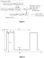
Figure 1 , electro-optic modulators (EOM) can also be used instead of acousto-optic modulators (AOM) to obtain the interrogation pulses out of a continuous wave light source. In an ideal case, it is assumed that the parts of fiber optic cable that do not lie within the input light pulse are completely dark and there is no backscattered signal from the dark regions. On the other hand, both AOMs and EOMs do not satisfy this perfect shut-off assumption and there is always a small amount of the light at every point of the fiber optic cable at any time. In literature, this phenomenon is defined as the Extinction Ratio (ER), which is measured as the ratio of the maximum optical power level that is injected into the fiber optic cable (pulse ON) to the minimum optical power level (pulse OFF) as illustrated inFigure 2 . - In phase-OTDR, the aim of using short duration pulses is independently interrogating specific portions of the cable, where the length of the actively interrogated cable portion is specified by the optic pulse width. This is only possible when no light is injected into the fiber optic cable outside of the input light pulse. The unwanted leakage optical signal (pulse OFF state or Pmin in
Figure 2 ) invalidates the phase-OTDR sensing principal. In this case, the interrogated portions of the fiber optic cable cannot be independent, the activities on different portions of the cable may affect each other. In other words, at any time, the backscattered signals coming from the whole fiber optic cable interfere with each other, which affects the overall sensing performance, especially for long cables. As a result, ER is an inherent limiting factor that has a direct effect on the detection performance of phase-OTDR based DAS systems [8], [9]. - In prior art, researchers try to solve the performance degradation problems in phase-OTDR systems encountered due to the finite Extinction Ratio (ER) in two different ways. Some researchers try to design better optical pulse generation mechanisms, in which the optic signal power in OFF state of the injected pulse is much lower than the commercially available EOMs or AOMs as stated in [8] and patent applications numbered
CN106961069A andGB2550789A GB2442745A US8537345B2 ,WO2017069724A1 ,WO2018039046A1 andWO2017127212A1 . Details of those methods will be given under the following sections. - In the first solution camp, there are some works that propose to use more than one commercially available EOM and/or AOM in a cascaded manner to decrease the Extinction Ratio. While cascading two EOMs (or AOMs) with 30 dB extinction ratio can result in 60 dB extinction ratio, it cannot be guaranteed to obtain extremely low extinction ratio (i.e. 120 dB), which is required for a good performance for long fiber optic cable [9]. Indeed, there is no manufacturer that produces EOMs or AOMs with a guaranteed higher than 70 dB extinction ratio.
- Instead of EOMs or AOMs, [8] proposes to use the nonlinear Kerr effect for optic pulse generation with extremely high extinction ratio. In this work, it is also theoretically shown that at least 90 dB extinction ratio is required for satisfying sensing performance at long fiber optic cables (> 40 km).
- In patent document numbered
CN106961069A , a high extinction ratio periodic pulse signal generating system based on a feedback structure is introduced. A feedback circuit formed by an optical phase shifter, an optical amplifier, a time delay optical fiber, and an adjustable optical fiber delay line is used to feed a part of light output by a modulator back to the input end of the modulator. The optical couplers are used to couple optical signals output by a CW laser with the optical modulator, and then repeated modulation is realized. By changing the intensities and the phases of the feedback signals of the feedback circuit and the splitting ratios of the two optical couplers, the output of the periodic pulse signals satisfying peak power and extinction ratio requirements is realized. - In UK patent document no.
GB2550789A - In the second solution camp, researchers make an effort to change the mechanisms in the transmitter and/or receiver parts of the classical phase-OTDR sensing system in such a way that, the unavoidable leakage light does not affect the sensing performance. In these solutions, the commercially available EOMs or AOMs are used in an optical pulse generation mechanism with different approaches as compared to classical ones.
- In GB patent no.
GB2442745A - In US patent numbered
US8537345B2 , temporally spaced multiple optic pulses possibly with different wavelengths are injected into the fiber optic cable. On the receiver side, the return signal is received in three different paths with different optical processes, which are two frequency shifted versions obtained with two different AOMs, and a delayed version obtained by a delay coil, before photodetectors. In this case, optic signals with different characteristics, i.e. normal phase-OTDR signal and the derivative of phase-OTDR signal, can be obtained with different carrier frequencies. Then, the derivative sensing technique can be applied to distributed acoustic sensing to increase the sensitivity as stated in the patent document. To apply the proposed solution, both the transmitter and receiver sides of the classical phase-OTDR system have to be changed. Also, the adjustment of temporal differences between injected pulses and the delay coil length can be very critical to obtain satisfying sensing performance. This work requires a careful selection of the carrier frequency differences between optic pulses and filter design to select the specific optic pulse pair at the receiver side. - In patent document no.
WO2017069724A1 , a sequence of optical pulses along an optical fiber of at least two different widths are used for interrogation to obtain a set of fade-resistant phase measurements. In another patent numberedWO2018039046A1 , the proposed interrogation system transmits a sequence of M simultaneously propagating light pulses through the optical fiber using a spatial mode selected from a set of N spatial modes. The receiver side detects an environmental perturbation in the optical fiber based on an evaluation of a propagation of the sequence of M light pulses through the optical fiber. - The application numbered
CN107144339A , a modulated pulse is used in interrogation process to realize accurate location and measurement of broadband vibration in a long-distance range. This work does not address the effects of leakage light on the system performance. - In patent
WO2017127212A1 , multiple optic pulses are transmitted into the multiple bundled fiber optic cables and spatial averaging of the back reflected signals received from these cables are computed to increase the signal to noise ratio (SNR). In this work, it is assumed that each spatial channel has an identical response to the acoustic vibrations and experiences the same phase of the acoustic vibrations. This assumption cannot be guaranteed. - All the works that use multiple optic pulses with different frequency/mode characteristics require careful selection of the carrier frequency/mode differences between optic pulses and filter designs to select the specific optic pulses at the receiver side.
- The invention relates to a phase sensitive optical time domain reflectometry based acoustic sensing system according to claim 1 and a phase sensitive optical time domain reflectometry based acoustic sensing method according to claim 14. Advantageous embodiments of the invention are described in the dependent claims.
- The invention aims to eliminate the degradation in sensing performance encountered due to the finite extinction ratio of the optical elements that are used to generate optical pulses. To do this, the classical OTDR and phase-OTDR concepts are merged to generate a modified optic pulse for interrogation with commercially available AOMs or EOMs. The characteristics of the light inside the fiber optic cable carry the properties of both classical OTDR and phase-OTDR systems. The proposed solution does not require any modifications in the receiver part of the phase-OTDR systems and can easily be used for any type of phase-OTDR system structure.
- For a better understanding of the present invention, the basic characteristics of the laser source used in classical OTDR and phase-OTDR applications should be understood clearly. In a chronological order, at first classical OTDR was demonstrated for measuring signal loss and detecting broken points along fiber optic cables. It uses optic pulses generated from an incoherent continuous wave (CW) laser source for interrogation with a very similar system architecture as the phase-OTDR system that is shown in
Figure 1 . Since the incoherent laser source has a large linewidth, the interfering back reflected optic signals due to the Rayleigh backscattering are at different frequencies. When there is a specific deformation on the fiber optic cable, the power of Rayleigh backscattered signal reflected back from that point is much larger than the power of Rayleigh backscattered signals reflected back from the other points. This is true regardless of the frequency of the reflected signal. Therefore, the incoherent laser source used in classical OTDR system is suitable for measuring intensity variations along the fiber optic cable. On the other hand, this system is not appropriate to sense small variations near or on the fiber optic cable. This type of activities result in very small changes (≈ 50nm) on the positions of the scattering centers, which are simply the imperfections in the fiber optic cable core. The changes in the positions of the scattering centers result in phase shifts in the received backscattered signals. When the input laser source is incoherent, a change in the position of a single scattering center is observed as multiple phase shifts due to the multiple frequencies in the reflected signal. The interference of back reflected signals with varying random phases cancels out and the small vibration near or on the fiber optic cable cannot be sensed. - As the laser source manufacturing technology improved, it became possible to produce laser sources with very narrow linewidth (highly coherent laser source). Using a highly coherent laser source solves the signal cancellation problem due to incoherent interference, since all the back reflected signals are almost at the same frequency. In that case, a change in the position of a single scattering center can be measured as a single phase shift, making it possible to sense small vibrations. As a result, using a highly coherent laser source instead of an incoherent laser source makes the interrogation process sensitive to small vibrations along the fiber optic cable.
- In practical use cases, there are always small vibrations along the fiber optic cable, apart from the target activity to be sensed. Under the infinite Extinction Ratio assumption, these spurious vibrations do not corrupt the measurements taken for the target activity. However, when the infinite Extinction Ratio assumption is violated, the undesired leakage light fills the full length of the fiber optic cable. As a result, the signals coherently interfering on the photodetector are not limited to those coming from section of the fiber optic cable that is illuminated by the ON state of the optic pulse. Potentially, back reflected light coming from anywhere on the fiber optic cable can coherently interfere on the photodetector, causing varying optical background noise.
- While incoherent laser source used in classical OTDR applications is insensitive to the small changes along the fiber optic cable, the highly coherent laser source used in phase-OTDR applications is over sensitive to the small changes at the outside the area of interest and the sensitivity level depends on the value of the extinction ratio and the length of the fiber optic cable. Therefore, the optimum solution for developing a better distributed acoustic sensing system is to use both incoherent and coherent laser sources in a joint manner at phase-OTDR system architecture. The key point of this invention is to integrate the incoherent laser source into the pulse generation mechanism of the phase-OTDR system to make the system insensitive to the activities outside of the point of interest without decreasing the sensitivity at the point of interest.
- The present invention differs from the existing solutions with:
- It is simple to apply to the existent various phase-OTDR system architectures.
- No modifications are required for the receiver side of the normal phase-OTDR systems.
- There is no required strict timing accuracies as compared to the multiple optic pulses scenario.
- There is no required algorithmic/software modifications to be used in the existent phase-OTDR systems.
- There is no required electronic re-design in the existent phase-OTDR systems. It is realized with fully optic elements.
-
-
Figure 1 illustrates the flow diagram of currently used classical phase-OTDR architecture in prior art. -
Figure 2 shows optical pulses injected into the fiber optic cable, where Pmax and Pmin are the maximum and minimum optical power level that is injected into the fiber optic cable, respectively and TW and TP are pulse width and pulse repetition period, respectively. -
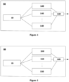
Figure 3 is the diagram of extinction ratio free phase sensitive optical time domain reflectometry based distributed acoustic sensing system. -
Figure 4 shows CW laser with large linewidth constructed by multiple optic frequency shifters. -
Figure 5 shows CW laser with large linewidth constructed by multiple optic phase shifters. -
- 10. Coherent laser source
- 20. First gain and filter block
- 30. Optic pulse generator
- 40. Radio frequency (RF) signal pulse generator
- 50. Combiner
- 60. Circulator
- 70. Sensing cable
- 80. Incoherent laser source
- 90. Second gain and filter block
- 100. Third gain and filter block
- 110. Photo detector
- 120. Analog to digital converter (ADC)
- 130. Processor
- 140. Frequency shifter
- 150. Phase shifter
- 160. Shifted signal combiner
- The invention is a phase sensitive optical time domain reflectometry based distributed acoustic sensing system that eliminates the degradation in sensing performance encountered due to the finite extinction ratio of the optical elements. In the system, a coherent laser source (10) generates CW laser with narrow linewidth (smaller than 100 Hz) for detecting vibration sources near a sensing cable (70). The phase-OTDR systems are based on measuring the changes in phase of the returned Rayleigh scattering signal and this measurement is possible when the light injected into the sensing cable (70) is coherent. Sensing cable (70) is a telecommunications grade fiber optic cable or any other type of fiber optic cable that can be used for remote sensing applications.
- The first gain and filter block (20) amplifies and filters the laser in order to satisfy the power and coherency criteria of the light to be injected into the cable (70). The block (20) contains an optical amplifier/attenuator to adjust the power of the light to be injected into the cable (70). Optic power can be adjusted by using EDFA. The amplified signal is then filtered to remove undesired signal components that are due to the non-ideal behavior of the amplifier. Several different optical filter designs can be used in this block (20).
- The optic pulse generator (30) shapes the CW laser into the narrow optic pulses (≈ 100 ns) with the desired pulse shape generated by RF signal pulse generator (40) for interrogation. The critical point in pulse generation is to obtain high extinction ratio, which is the ratio of the optic power within pulse (the ON state) and the optic power outside pulse (the OFF state). Optic pulse can be generated by using Acousto-optic Modulator (AOM) or Electro-optic Modulator (EOM) or any other optical component such as Kerr medium. The shape of the optic pulse can vary based on the application, i.e. rectangular pulse, saw tooth pulse, etc.
- On the other path, an incoherent laser source (80) generates CW laser with large linewidth for degrading the undesired coherent interference effect for the leakage light injected into the cable when optic pulse generator (30) is in OFF state. The incoherent laser source (80) can be constructed with:
- Laser sources that are commonly used in classical OTDR applications but not used in phase-OTDR applications due to the large linewidth,
- The combined multiple CW lasers with narrow linewidth as shown in
Figure 4 . Frequency shifters (140) can shift the source laser frequency with a fixed value or shifting value can be changed with an external signal source. - The combination of multiple different phase shifted versions of a single CW laser with narrow linewidth such in
Figure 5 . Phase shifters (150) can shift the source laser phase with a fixed value or shifting value can be changed with an external signal source. - All of the other possibilities for generating large linewidth laser can also be used throughout this design.
- The second gain and filter block (90) amplifies/attenuates and filters the incoherent CW laser coming from the incoherent laser source (80) to satisfy the power and incoherency criteria. This part contains an optical amplifier/attenuator to adjust the power of the incoherent light injected into the sensing cable (70) such that its power is similar to the power of the coherent leakage light injected when the optic pulse generator (30) is in OFF state. Several different optical filter designs can be used in this block (90). This filter block should shape the frequency spectrum of the light injected into the sensing cable (70) such that the resulting incoherent light has a wide linewidth with a total power that is similar to the power of the coherent leakage light injected when the optic pulse generator (30) is in OFF state. For example, gain and filter block (90) can be constructed as a combination of first gain and filter block (20) combined with optic pulse generator (30) and RF signal pulse generator (40), where RF signal pulse generator (40) is always in OFF state.
- The combiner (50) combines the optic signal coming from the optic pulse generator (30) and the second gain and filter block (90) and forwards the combined optic signal to a circulator (60). The circulator (60) injects the combined optic signal to the sensing cable (70) and forwards back reflected Rayleigh scattering signals coming from the sensing cable (70) to the third gain and filter block (100). The third gain and filter block (100) adjusts the power level of the returned Rayleigh backscattered signal and filters out the undesired frequency components in the returned Rayleigh backscattered signal for obtaining the best performance in the receiver block. The receiver block consists of a photo detector (110), an ADC (120) and a processor (130). The receiver block can be in the form of direct detection, heterodyne detection, homodyne detection or any other receiver format that can be used in distributed acoustic sensing applications. The photo detector (110) measures the optic power of the returned Rayleigh backscattered signal as an electrical signal (voltage or current). The photo detector block (110) may consist of a single photo detector or multiple photo detectors for measuring the returned Rayleigh backscattered optical signal based on the preferred embodiment. The ADC (120) digitizes the measured analog optic power to be processed by the processor (130). The single or multiple ADC (120) may be used for measuring based on the preferred embodiment.
- In the present invention, only the optic pulse generation mechanism of the phase-OTDR architecture is modified and the receiver side is not changed as shown in
Figure 3 . A second path is added into the transmitter side to change the characteristics of the optical pulse injected into the sensing cable (70) for interrogation. On the second path, incoherent laser source (80) is used instead of the highly coherent one with the center frequency same as the coherent laser source (10) in the first path. In a possible implementation, the other optical and electronic parts may be kept identical to the first path. The optical signals generated at these two paths are combined by the combiner (50) and fed into the sensing cable (70). In this configuration, the AOM in the first path is driven by very narrow (≈ 100 ns) electronic pulse with ON and OFF state and the AOM in the second path is driven continuously with OFF state. Therefore, while the first path generates optical pulse, the second path generates only the leakage optical signal with a much higher linewidth as compared to the optic signal in the first path. - The optic pulse injected into the sensing cable (70) can be represented as


- Note that, when the AOMs have similar low extinction ratios, i.e., ε1 ≈ ε2 ≪ 1, the injected optic signal p(t) can be simplified as

-
- [1] Hill, D., "Distributed acoustic sensing (das): Theory and applications," in [Frontiers in Optics 2015], Frontiers in Optics 2015, FTh4E.1, Optical Society of America (2015).
- [2] Makarenko, A. V., "Deep learning algorithms for signal recognition in long perimeter monitoring distributed fiber optic sensors," IEEE 26th Int. Workshop on Machine Learning for Signal Processing (MLSP), 1-11 (2016).
- [3] Aktas, M., Akgun, T., Demircin, M. U., and Buyukaydin, D., "Deep learning based multi-thread classification for phase-otdr fiber optic distributed acoustic sensing applications," in [Fiber Optic Sensors and Applications XIV], Proc. SPIE 10208 (2017).
- [4] Juarez, J. C., Maier, E. W., Choi, K. N., and Taylor, H. F., "Distributed fiberoptic intrusion sensor system," J. Lightw. Technol. 23, 2081-2087 (2005).
- [5] Juarez, J. C. and Taylor, H. F., "Field test of a distributed fiber-optic intrusion sensor system for long perimeters," Applied Optics 46, 1968-1971 (2007).
- [6] Qin, Z., Chen, L., and Bao, X., "Wavelet denoising method for improving detection performance of distributed vibration sensor," IEEE Photonic Tech. Lett. 24, 542-544 (2012).
- [7] Koyamada, Y., Imahama, M., Kubota, K., and Hogari, K., "Fiber-optic distributed strain and temperature sensing with very high measurand resolution over long range using coherent otdr," J. Lightw. Technol. 27, 1142-1146 (2009).
- [8] Baker, C., Vanus, B., Wuilpart, M., Chen, L., and Bao, X., "Enhancement of optical pulse extinction-ratio using the nonlinear Kerr effect for phase-otdr," Optics Express 24, 19424-19434 (2016).
- [9] M. Aktas, H. M. and Akgun, T., "A model-based analysis of extinction ratio effects on phase-OTDR distributed acoustic sensing system performance," SPIE Photonics West (2018).
Claims (14)
- A phase sensitive optical time domain reflectometry based distributed acoustic sensing system eliminating the degradation in sensing performance encountered due to the finite extinction ratio of the optical elements, provided with:• a sensing cable (70) used for remote sensing applications,• a coherent laser source (10) configured to generate CW laser with narrow linewidth for detecting vibration sources near a sensing cable (70),• first gain and filter block (20) configured to amplify the coherent CW laser to adjust the power and filtering the laser to be injected into the cable to eliminate possible undesired frequency components introduced during power adjustment,• an optic pulse generator (30) configured to shape the CW laser into the narrow optic pulses with the desired pulse shape generated by RF signal pulse generator (40),• a circulator (60) configured to inject the optic signal to the sensing cable (70) and forwarding back reflected Rayleigh scattering signals coming from cable to third gain and filter block (100),• the third gain and filter block (100) configured to adjust the power level of the signal and filtering out the undesired frequency components on the returned Rayleigh backscattered signal,• a receiver block configured to measure the optic power of the returned Rayleigh backscattered signal, digitizing the measured analog optic power and processing the digitized optic signal power, the system characterised by comprising;• an incoherent laser source (80) configured to generate CW laser with large linewidth for degrading the coherence interference effect or coherence length for the light injected into the cable when optic pulse generator (30) is in OFF state,• second gain and filter block (90) configured to adjust the power of the incoherent light and filtering it such that the resulting incoherent light has a wide linewidth with its power is similar to the power of the coherent leakage light injected when the optic pulse generator (30) is in OFF state,• a combiner (50) configured to combine the optic signal coming from optic pulse generator (30) and second gain and filter block (90) and forwarding the combined optic signal to the circulator (60).
- The system according to the claim 1, the optic pulse, p(t), injected into the fiber optic cable can be represented as


- The system according to the claim 2, wherein the injected optic signal p(t) can be simplified as

- The system according to the claim 1, wherein the optic pulse generator (30) is an acousto-optic modulator or a electro-optic modulator or a Kerr medium.
- The system according to the claim 1, wherein the optic power is adjusted by using Erbium Doped Fiber Amplifier in gain and filter blocks (20, 90, 100).
- The system according to the claim 1, wherein the receiver block consists of a photo detector (110) measuring the optic power, an analog to digital converter (120) and a processor (130) processing the digitized optic signal power.
- The system according to the claim 1 or 6, comprising a photo detector block consists of a single photo detector (110) or multiple photo detectors (110) for measuring the returned Rayleigh backscattered optical signal.
- The system according to the claim 1, wherein the receiver block is in the form of direct detection, heterodyne detection, homodyne detection or any other receiver format that can be used in distributed acoustic sensing.
- The system according to the claim 1, wherein the incoherent laser source (80) is a combined multiple CW lasers with narrow linewidth shifted with optical frequency shifters (140).
- The system according to the claim 1, wherein the incoherent laser source (80) is a combined multiple CW lasers with narrow linewidth shifted with optical phase shifters (150).
- The system according to the claim 9 or 10, wherein the frequency / phase shifters (140, 150) shift laser frequency / phase with a fixed value or shifting value changed with an external signal source.
- The system according to the claim 1, wherein the sensing cable (70) is a fiber optic cable.
- The system according to the claim 1, wherein the second gain and filter block (90) is realized with the first gain and filter block (20) combined with optic pulse generator (30) and signal pulse generator (40), where signal pulse generator (40) is always in OFF state.
- A phase sensitive optical time domain reflectometry based distributed acoustic sensing method eliminating the degradation in sensing performance encountered due to the finite extinction ratio of the optical elements, comprising the process steps of;• generating CW laser with narrow linewidth by a coherent laser source for detecting vibration sources near a fiber optic cable,• adjusting the power of the CW laser and filtering to eliminate possible undesired frequency components introduced during power adjustment,• shaping the CW laser into the narrow optic pulses by a optic pulse generator with the desired pulse shape,• generating CW laser with large linewidth by an incoherent laser source for degrading the coherence interference effect or coherence length for the light injected into the cable when optic pulse generator is in OFF state,• adjusting the power of the incoherent light and filtering it such that the resulting incoherent light has a wide linewidth with its power is similar to the power of the coherent leakage light injected when the optic pulse generator is in OFF state,• combining the optic signals coming from optic paths with a combiner and forwarding the combined optic signal to a circulator,• injecting optic signal to cable and forwarding back reflected Rayleigh scattering signals coming from cable to a gain and filter block,• adjusting the power level of the signal and filtering out the undesired frequency components on the returned Rayleigh backscattered signal,• measuring the optic power of the returned Rayleigh backscattered signal,• digitizing the measured analog optic power and processing the digitized optic signal power.
Applications Claiming Priority (1)
| Application Number | Priority Date | Filing Date | Title |
|---|---|---|---|
| PCT/TR2018/050423 WO2020032878A1 (en) | 2018-08-08 | 2018-08-08 | Extinction ratio free phase sensitive optical time domain reflectometry based distributed acoustic sensing system |
Publications (2)
| Publication Number | Publication Date |
|---|---|
| EP3833943A1 EP3833943A1 (en) | 2021-06-16 |
| EP3833943B1 true EP3833943B1 (en) | 2023-10-04 |
Family
ID=66240187
Family Applications (1)
| Application Number | Title | Priority Date | Filing Date |
|---|---|---|---|
| EP18869466.5A Active EP3833943B1 (en) | 2018-08-08 | 2018-08-08 | Extinction ratio free phase sensitive optical time domain reflectometry based distributed acoustic sensing system |
Country Status (3)
| Country | Link |
|---|---|
| EP (1) | EP3833943B1 (en) |
| CA (1) | CA3104086C (en) |
| WO (1) | WO2020032878A1 (en) |
Families Citing this family (3)
| Publication number | Priority date | Publication date | Assignee | Title |
|---|---|---|---|---|
| CN111912513B (en) * | 2020-07-14 | 2022-03-22 | 国家电网有限公司 | Identification method of excavator construction event along optical cable based on phi-OTDR |
| CN112504430B (en) * | 2020-11-26 | 2022-03-01 | 南京大学 | Tower structure health monitoring method based on vibration sensitive optical fiber sensing technology |
| US20240012167A1 (en) * | 2022-07-05 | 2024-01-11 | Exfo Inc. | Method and apparatus of distributed acoustic sensing |
Family Cites Families (8)
| Publication number | Priority date | Publication date | Assignee | Title |
|---|---|---|---|---|
| GB2442745B (en) | 2006-10-13 | 2011-04-06 | At & T Corp | Method and apparatus for acoustic sensing using multiple optical pulses |
| GB0917150D0 (en) * | 2009-09-30 | 2009-11-11 | Qinetiq Ltd | Phase based sensing |
| GB2550789B (en) | 2015-04-07 | 2021-03-03 | Halliburton Energy Services Inc | Reducing noise in a distributed acoustic sensing system downhole |
| US10775230B2 (en) | 2015-10-19 | 2020-09-15 | Halliburton Energy Services, Inc. | Distributed acoustic sensing systems and methods employing multiple pulse widths |
| US10345138B2 (en) | 2016-01-22 | 2019-07-09 | Nec Corporation | Method to increase the signal to noise ratio of distributed acoustic sensing by spatial averaging |
| US10466172B2 (en) | 2016-08-22 | 2019-11-05 | Nec Corporation | Distributed acoustic sensing in a multimode optical fiber using distributed mode coupling and delay |
| CN106961069B (en) | 2017-04-25 | 2019-02-01 | 电子科技大学 | High Extinction Ratio periodic pulse signal generation system and method based on feedback arrangement |
| CN107144339A (en) | 2017-05-17 | 2017-09-08 | 长沙理工大学 | A kind of distributed optical fiber sensing system based on modulation pulse technique |
-
2018
- 2018-08-08 CA CA3104086A patent/CA3104086C/en active Active
- 2018-08-08 WO PCT/TR2018/050423 patent/WO2020032878A1/en unknown
- 2018-08-08 EP EP18869466.5A patent/EP3833943B1/en active Active
Also Published As
| Publication number | Publication date |
|---|---|
| CA3104086A1 (en) | 2020-02-13 |
| US20210140814A1 (en) | 2021-05-13 |
| EP3833943A1 (en) | 2021-06-16 |
| CA3104086C (en) | 2023-08-01 |
| RU2768226C1 (en) | 2022-03-23 |
| WO2020032878A1 (en) | 2020-02-13 |
Similar Documents
| Publication | Publication Date | Title |
|---|---|---|
| EP2084505B1 (en) | Detecting a disturbance in the phase of light propagating in an optical waveguide | |
| KR100930342B1 (en) | Distribution fiber optic sensor system | |
| CN102227615B (en) | Distributed optical fiber sensor | |
| JP3780322B2 (en) | Distributed strain and temperature sensing system | |
| CN113405577B (en) | Measuring method and measuring device | |
| EP3833943B1 (en) | Extinction ratio free phase sensitive optical time domain reflectometry based distributed acoustic sensing system | |
| JP5322162B2 (en) | Distributed fiber optic pressure sensor | |
| EP1338876A2 (en) | Optical time domain reflectometry | |
| CN111373613A (en) | Customized distributed amplification for fiber sensing | |
| RU2573614C2 (en) | Sensor and method of measurement | |
| US11320302B2 (en) | High-rate distributed acoustic sensing using high-power light pulses | |
| CA2247293A1 (en) | Distributed sensing apparatus | |
| WO2004102840A1 (en) | Optic communication or transmission media sensing | |
| US20230125375A1 (en) | Few-mode rayleigh-based distributed fiber sensor for simultaneous temperature and strain sensing | |
| CA2615327C (en) | Optical fiber characteristic measuring system | |
| Peng et al. | 106km fully-distributed fiber-optic fence based on P-OTDR with 2nd-order Raman amplification | |
| US11959799B2 (en) | Extinction ratio free phase sensitive optical time domain reflectometry based distributed acoustic sensing system | |
| RU2768226C9 (en) | Distributed acoustic probing system based on phase-sensitive optical reflectometry in time domain without effect of attenuation coefficient | |
| CN112118043B (en) | COTDR (coherent optical time domain reflectometry) measuring method and device based on PSK (phase Shift keying) pulse coding | |
| Sandah et al. | Spectral Shadowing Compensation in Double-pulse FBG-assisted φ-OTDR | |
| Liu et al. | Monitoring Distance Enhancement with Chaotic Laser for OTDR System | |
| KR102644918B1 (en) | sensitiveness improvement type distributed acostic sensor | |
| Ryu et al. | Enhanced measurement range of single end accessible Brillouin optical correlation domain analysis incorporating time-domain data processing | |
| Lu et al. | Dual functionality of wavelength scanning coherent optical time domain reflectometer | |
| CN116707628A (en) | Method and device for transmitting signals |
Legal Events
| Date | Code | Title | Description |
|---|---|---|---|
| STAA | Information on the status of an ep patent application or granted ep patent |
Free format text: STATUS: UNKNOWN |
|
| STAA | Information on the status of an ep patent application or granted ep patent |
Free format text: STATUS: THE INTERNATIONAL PUBLICATION HAS BEEN MADE |
|
| STAA | Information on the status of an ep patent application or granted ep patent |
Free format text: STATUS: THE INTERNATIONAL PUBLICATION HAS BEEN MADE |
|
| PUAI | Public reference made under article 153(3) epc to a published international application that has entered the european phase |
Free format text: ORIGINAL CODE: 0009012 |
|
| STAA | Information on the status of an ep patent application or granted ep patent |
Free format text: STATUS: REQUEST FOR EXAMINATION WAS MADE |
|
| 17P | Request for examination filed |
Effective date: 20210212 |
|
| AK | Designated contracting states |
Kind code of ref document: A1 Designated state(s): AL AT BE BG CH CY CZ DE DK EE ES FI FR GB GR HR HU IE IS IT LI LT LU LV MC MK MT NL NO PL PT RO RS SE SI SK SM TR |
|
| DAV | Request for validation of the european patent (deleted) | ||
| DAX | Request for extension of the european patent (deleted) | ||
| GRAP | Despatch of communication of intention to grant a patent |
Free format text: ORIGINAL CODE: EPIDOSNIGR1 |
|
| STAA | Information on the status of an ep patent application or granted ep patent |
Free format text: STATUS: GRANT OF PATENT IS INTENDED |
|
| INTG | Intention to grant announced |
Effective date: 20230504 |
|
| P01 | Opt-out of the competence of the unified patent court (upc) registered |
Effective date: 20230529 |
|
| GRAS | Grant fee paid |
Free format text: ORIGINAL CODE: EPIDOSNIGR3 |
|
| GRAA | (expected) grant |
Free format text: ORIGINAL CODE: 0009210 |
|
| STAA | Information on the status of an ep patent application or granted ep patent |
Free format text: STATUS: THE PATENT HAS BEEN GRANTED |
|
| AK | Designated contracting states |
Kind code of ref document: B1 Designated state(s): AL AT BE BG CH CY CZ DE DK EE ES FI FR GB GR HR HU IE IS IT LI LT LU LV MC MK MT NL NO PL PT RO RS SE SI SK SM TR |
|
| REG | Reference to a national code |
Ref country code: GB Ref legal event code: FG4D |
|
| REG | Reference to a national code |
Ref country code: CH Ref legal event code: EP |
|
| REG | Reference to a national code |
Ref country code: DE Ref legal event code: R096 Ref document number: 602018058900 Country of ref document: DE |
|
| REG | Reference to a national code |
Ref country code: IE Ref legal event code: FG4D |
|
| REG | Reference to a national code |
Ref country code: LT Ref legal event code: MG9D |
|
| REG | Reference to a national code |
Ref country code: NL Ref legal event code: MP Effective date: 20231004 |
|
| PG25 | Lapsed in a contracting state [announced via postgrant information from national office to epo] |
Ref country code: NL Free format text: LAPSE BECAUSE OF FAILURE TO SUBMIT A TRANSLATION OF THE DESCRIPTION OR TO PAY THE FEE WITHIN THE PRESCRIBED TIME-LIMIT Effective date: 20231004 |
|
| PG25 | Lapsed in a contracting state [announced via postgrant information from national office to epo] |
Ref country code: GR Free format text: LAPSE BECAUSE OF FAILURE TO SUBMIT A TRANSLATION OF THE DESCRIPTION OR TO PAY THE FEE WITHIN THE PRESCRIBED TIME-LIMIT Effective date: 20240105 |
|
| PG25 | Lapsed in a contracting state [announced via postgrant information from national office to epo] |
Ref country code: IS Free format text: LAPSE BECAUSE OF FAILURE TO SUBMIT A TRANSLATION OF THE DESCRIPTION OR TO PAY THE FEE WITHIN THE PRESCRIBED TIME-LIMIT Effective date: 20240204 |