EP3832986B1 - Gestion des balises d'appareils d'éclairage distribués - Google Patents
Gestion des balises d'appareils d'éclairage distribués Download PDFInfo
- Publication number
- EP3832986B1 EP3832986B1 EP20217863.8A EP20217863A EP3832986B1 EP 3832986 B1 EP3832986 B1 EP 3832986B1 EP 20217863 A EP20217863 A EP 20217863A EP 3832986 B1 EP3832986 B1 EP 3832986B1
- Authority
- EP
- European Patent Office
- Prior art keywords
- light fixture
- beacons
- location
- light
- rssi
- Prior art date
- Legal status (The legal status is an assumption and is not a legal conclusion. Google has not performed a legal analysis and makes no representation as to the accuracy of the status listed.)
- Active
Links
- 238000004891 communication Methods 0.000 claims description 68
- 230000005540 biological transmission Effects 0.000 claims description 52
- 230000033001 locomotion Effects 0.000 claims description 50
- 238000000034 method Methods 0.000 claims description 22
- 230000001133 acceleration Effects 0.000 claims description 17
- 238000005259 measurement Methods 0.000 claims description 4
- 238000001914 filtration Methods 0.000 claims description 3
- 238000005070 sampling Methods 0.000 claims description 3
- 230000001413 cellular effect Effects 0.000 description 3
- 238000012544 monitoring process Methods 0.000 description 3
- 230000002457 bidirectional effect Effects 0.000 description 2
- 238000001514 detection method Methods 0.000 description 2
- 230000000694 effects Effects 0.000 description 2
- 230000010354 integration Effects 0.000 description 2
- 230000004044 response Effects 0.000 description 2
- 240000007320 Pinus strobus Species 0.000 description 1
- 238000013459 approach Methods 0.000 description 1
- 230000015572 biosynthetic process Effects 0.000 description 1
- 230000001351 cycling effect Effects 0.000 description 1
- 230000001419 dependent effect Effects 0.000 description 1
- 238000009429 electrical wiring Methods 0.000 description 1
- 238000005516 engineering process Methods 0.000 description 1
- 230000007613 environmental effect Effects 0.000 description 1
- 238000005755 formation reaction Methods 0.000 description 1
- 230000005484 gravity Effects 0.000 description 1
- 230000000977 initiatory effect Effects 0.000 description 1
- 230000002452 interceptive effect Effects 0.000 description 1
- 230000004807 localization Effects 0.000 description 1
- 238000012545 processing Methods 0.000 description 1
- 239000013589 supplement Substances 0.000 description 1
- 230000001502 supplementing effect Effects 0.000 description 1
- 230000001360 synchronised effect Effects 0.000 description 1
- 238000012360 testing method Methods 0.000 description 1
- 230000001960 triggered effect Effects 0.000 description 1
- 230000000007 visual effect Effects 0.000 description 1
Images


Classifications
-
- G—PHYSICS
- G01—MEASURING; TESTING
- G01S—RADIO DIRECTION-FINDING; RADIO NAVIGATION; DETERMINING DISTANCE OR VELOCITY BY USE OF RADIO WAVES; LOCATING OR PRESENCE-DETECTING BY USE OF THE REFLECTION OR RERADIATION OF RADIO WAVES; ANALOGOUS ARRANGEMENTS USING OTHER WAVES
- G01S1/00—Beacons or beacon systems transmitting signals having a characteristic or characteristics capable of being detected by non-directional receivers and defining directions, positions, or position lines fixed relatively to the beacon transmitters; Receivers co-operating therewith
- G01S1/02—Beacons or beacon systems transmitting signals having a characteristic or characteristics capable of being detected by non-directional receivers and defining directions, positions, or position lines fixed relatively to the beacon transmitters; Receivers co-operating therewith using radio waves
- G01S1/04—Details
- G01S1/042—Transmitters
- G01S1/0423—Mounting or deployment thereof
- G01S1/0426—Collocated with electrical equipment other than beacons
-
- G—PHYSICS
- G01—MEASURING; TESTING
- G01S—RADIO DIRECTION-FINDING; RADIO NAVIGATION; DETERMINING DISTANCE OR VELOCITY BY USE OF RADIO WAVES; LOCATING OR PRESENCE-DETECTING BY USE OF THE REFLECTION OR RERADIATION OF RADIO WAVES; ANALOGOUS ARRANGEMENTS USING OTHER WAVES
- G01S1/00—Beacons or beacon systems transmitting signals having a characteristic or characteristics capable of being detected by non-directional receivers and defining directions, positions, or position lines fixed relatively to the beacon transmitters; Receivers co-operating therewith
- G01S1/02—Beacons or beacon systems transmitting signals having a characteristic or characteristics capable of being detected by non-directional receivers and defining directions, positions, or position lines fixed relatively to the beacon transmitters; Receivers co-operating therewith using radio waves
- G01S1/68—Marker, boundary, call-sign, or like beacons transmitting signals not carrying directional information
-
- G—PHYSICS
- G01—MEASURING; TESTING
- G01S—RADIO DIRECTION-FINDING; RADIO NAVIGATION; DETERMINING DISTANCE OR VELOCITY BY USE OF RADIO WAVES; LOCATING OR PRESENCE-DETECTING BY USE OF THE REFLECTION OR RERADIATION OF RADIO WAVES; ANALOGOUS ARRANGEMENTS USING OTHER WAVES
- G01S5/00—Position-fixing by co-ordinating two or more direction or position line determinations; Position-fixing by co-ordinating two or more distance determinations
- G01S5/02—Position-fixing by co-ordinating two or more direction or position line determinations; Position-fixing by co-ordinating two or more distance determinations using radio waves
- G01S5/14—Determining absolute distances from a plurality of spaced points of known location
-
- G—PHYSICS
- G08—SIGNALLING
- G08C—TRANSMISSION SYSTEMS FOR MEASURED VALUES, CONTROL OR SIMILAR SIGNALS
- G08C17/00—Arrangements for transmitting signals characterised by the use of a wireless electrical link
- G08C17/02—Arrangements for transmitting signals characterised by the use of a wireless electrical link using a radio link
-
- H—ELECTRICITY
- H04—ELECTRIC COMMUNICATION TECHNIQUE
- H04L—TRANSMISSION OF DIGITAL INFORMATION, e.g. TELEGRAPHIC COMMUNICATION
- H04L67/00—Network arrangements or protocols for supporting network services or applications
- H04L67/01—Protocols
- H04L67/12—Protocols specially adapted for proprietary or special-purpose networking environments, e.g. medical networks, sensor networks, networks in vehicles or remote metering networks
-
- H—ELECTRICITY
- H04—ELECTRIC COMMUNICATION TECHNIQUE
- H04W—WIRELESS COMMUNICATION NETWORKS
- H04W4/00—Services specially adapted for wireless communication networks; Facilities therefor
- H04W4/02—Services making use of location information
- H04W4/025—Services making use of location information using location based information parameters
-
- H—ELECTRICITY
- H04—ELECTRIC COMMUNICATION TECHNIQUE
- H04W—WIRELESS COMMUNICATION NETWORKS
- H04W4/00—Services specially adapted for wireless communication networks; Facilities therefor
- H04W4/02—Services making use of location information
- H04W4/029—Location-based management or tracking services
-
- H—ELECTRICITY
- H04—ELECTRIC COMMUNICATION TECHNIQUE
- H04W—WIRELESS COMMUNICATION NETWORKS
- H04W4/00—Services specially adapted for wireless communication networks; Facilities therefor
- H04W4/06—Selective distribution of broadcast services, e.g. multimedia broadcast multicast service [MBMS]; Services to user groups; One-way selective calling services
-
- H—ELECTRICITY
- H04—ELECTRIC COMMUNICATION TECHNIQUE
- H04W—WIRELESS COMMUNICATION NETWORKS
- H04W4/00—Services specially adapted for wireless communication networks; Facilities therefor
- H04W4/80—Services using short range communication, e.g. near-field communication [NFC], radio-frequency identification [RFID] or low energy communication
-
- H—ELECTRICITY
- H05—ELECTRIC TECHNIQUES NOT OTHERWISE PROVIDED FOR
- H05B—ELECTRIC HEATING; ELECTRIC LIGHT SOURCES NOT OTHERWISE PROVIDED FOR; CIRCUIT ARRANGEMENTS FOR ELECTRIC LIGHT SOURCES, IN GENERAL
- H05B47/00—Circuit arrangements for operating light sources in general, i.e. where the type of light source is not relevant
- H05B47/10—Controlling the light source
- H05B47/105—Controlling the light source in response to determined parameters
- H05B47/11—Controlling the light source in response to determined parameters by determining the brightness or colour temperature of ambient light
-
- H—ELECTRICITY
- H05—ELECTRIC TECHNIQUES NOT OTHERWISE PROVIDED FOR
- H05B—ELECTRIC HEATING; ELECTRIC LIGHT SOURCES NOT OTHERWISE PROVIDED FOR; CIRCUIT ARRANGEMENTS FOR ELECTRIC LIGHT SOURCES, IN GENERAL
- H05B47/00—Circuit arrangements for operating light sources in general, i.e. where the type of light source is not relevant
- H05B47/10—Controlling the light source
- H05B47/105—Controlling the light source in response to determined parameters
- H05B47/115—Controlling the light source in response to determined parameters by determining the presence or movement of objects or living beings
- H05B47/125—Controlling the light source in response to determined parameters by determining the presence or movement of objects or living beings by using cameras
-
- H—ELECTRICITY
- H05—ELECTRIC TECHNIQUES NOT OTHERWISE PROVIDED FOR
- H05B—ELECTRIC HEATING; ELECTRIC LIGHT SOURCES NOT OTHERWISE PROVIDED FOR; CIRCUIT ARRANGEMENTS FOR ELECTRIC LIGHT SOURCES, IN GENERAL
- H05B47/00—Circuit arrangements for operating light sources in general, i.e. where the type of light source is not relevant
- H05B47/10—Controlling the light source
- H05B47/175—Controlling the light source by remote control
- H05B47/19—Controlling the light source by remote control via wireless transmission
-
- H—ELECTRICITY
- H05—ELECTRIC TECHNIQUES NOT OTHERWISE PROVIDED FOR
- H05B—ELECTRIC HEATING; ELECTRIC LIGHT SOURCES NOT OTHERWISE PROVIDED FOR; CIRCUIT ARRANGEMENTS FOR ELECTRIC LIGHT SOURCES, IN GENERAL
- H05B47/00—Circuit arrangements for operating light sources in general, i.e. where the type of light source is not relevant
- H05B47/10—Controlling the light source
- H05B47/175—Controlling the light source by remote control
- H05B47/196—Controlling the light source by remote control characterised by user interface arrangements
- H05B47/1965—Controlling the light source by remote control characterised by user interface arrangements using handheld communication devices
-
- G—PHYSICS
- G01—MEASURING; TESTING
- G01S—RADIO DIRECTION-FINDING; RADIO NAVIGATION; DETERMINING DISTANCE OR VELOCITY BY USE OF RADIO WAVES; LOCATING OR PRESENCE-DETECTING BY USE OF THE REFLECTION OR RERADIATION OF RADIO WAVES; ANALOGOUS ARRANGEMENTS USING OTHER WAVES
- G01S2201/00—Indexing scheme relating to beacons or beacon systems transmitting signals capable of being detected by non-directional receivers and defining directions, positions, or position lines fixed relatively to the beacon transmitters
- G01S2201/01—Indexing scheme relating to beacons or beacon systems transmitting signals capable of being detected by non-directional receivers and defining directions, positions, or position lines fixed relatively to the beacon transmitters adapted for specific applications or environments
- G01S2201/02—Indoor positioning, e.g. in covered car-parks, mining facilities, warehouses
-
- G—PHYSICS
- G08—SIGNALLING
- G08C—TRANSMISSION SYSTEMS FOR MEASURED VALUES, CONTROL OR SIMILAR SIGNALS
- G08C2201/00—Transmission systems of control signals via wireless link
- G08C2201/50—Receiving or transmitting feedback, e.g. replies, status updates, acknowledgements, from the controlled devices
- G08C2201/51—Remote controlling of devices based on replies, status thereof
-
- G—PHYSICS
- G08—SIGNALLING
- G08C—TRANSMISSION SYSTEMS FOR MEASURED VALUES, CONTROL OR SIMILAR SIGNALS
- G08C2201/00—Transmission systems of control signals via wireless link
- G08C2201/90—Additional features
- G08C2201/93—Remote control using other portable devices, e.g. mobile phone, PDA, laptop
-
- H—ELECTRICITY
- H05—ELECTRIC TECHNIQUES NOT OTHERWISE PROVIDED FOR
- H05B—ELECTRIC HEATING; ELECTRIC LIGHT SOURCES NOT OTHERWISE PROVIDED FOR; CIRCUIT ARRANGEMENTS FOR ELECTRIC LIGHT SOURCES, IN GENERAL
- H05B47/00—Circuit arrangements for operating light sources in general, i.e. where the type of light source is not relevant
- H05B47/10—Controlling the light source
- H05B47/105—Controlling the light source in response to determined parameters
-
- H—ELECTRICITY
- H05—ELECTRIC TECHNIQUES NOT OTHERWISE PROVIDED FOR
- H05B—ELECTRIC HEATING; ELECTRIC LIGHT SOURCES NOT OTHERWISE PROVIDED FOR; CIRCUIT ARRANGEMENTS FOR ELECTRIC LIGHT SOURCES, IN GENERAL
- H05B47/00—Circuit arrangements for operating light sources in general, i.e. where the type of light source is not relevant
- H05B47/10—Controlling the light source
- H05B47/165—Controlling the light source following a pre-assigned programmed sequence; Logic control [LC]
-
- Y—GENERAL TAGGING OF NEW TECHNOLOGICAL DEVELOPMENTS; GENERAL TAGGING OF CROSS-SECTIONAL TECHNOLOGIES SPANNING OVER SEVERAL SECTIONS OF THE IPC; TECHNICAL SUBJECTS COVERED BY FORMER USPC CROSS-REFERENCE ART COLLECTIONS [XRACs] AND DIGESTS
- Y02—TECHNOLOGIES OR APPLICATIONS FOR MITIGATION OR ADAPTATION AGAINST CLIMATE CHANGE
- Y02B—CLIMATE CHANGE MITIGATION TECHNOLOGIES RELATED TO BUILDINGS, e.g. HOUSING, HOUSE APPLIANCES OR RELATED END-USER APPLICATIONS
- Y02B20/00—Energy efficient lighting technologies, e.g. halogen lamps or gas discharge lamps
- Y02B20/40—Control techniques providing energy savings, e.g. smart controller or presence detection
Definitions
- the described embodiments relate generally to lighting. More particularly, the described embodiments relate to distributed light fixture beacon management.
- CN 104 869 536 A (UNIV TSINGHUA), 26 August 2015 (2015-08-26), relates to a method of automatically updating wireless indoor positioning fingerprint map and device.
- the lighting systems are advantageous because they typically reduce energy costs by automatically lowering light levels or turning off devices and appliances when not needed, and they can allow all devices in the system to be controlled from one location.
- Decentralized lighting systems address many of the above-described issues. However, decentralized lighting systems require commissioning of lighting devices associated with the lighting systems.
- a plurality of other light fixtures transmit beacons at a transmission signal power level of less than the threshold, enabling a mobile device to receive beacons from the light fixture and the other light fixtures and estimate a location of the mobile device, wherein estimating the location of the mobile device includes measuring a receive signal strength of the received beacons, estimating a distance between the mobile device and the light fixture and between the mobile device and each of the other light fixtures, and estimating the location by triangulating the estimated distances.
- each of the light fixture and the other light fixtures transmit the beacons after sensing motion, thereby limiting how many light fixtures transmit beacons.
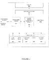
- Figure 7 shows a commissioning a gateway of a lighting control system, according to an embodiment.
- the embodiments for commissioning a light fixture can be extended to further include commissioning of other devices of the lighting system, such as, gateways (such as, gateway 740), sensors (such as, sensor system 780), which can themselves by standalone devices, and switches.
- gateways such as, gateway 740
- sensors such as, sensor system 780
- the light fixtures 821, 822, 823, 824, 825, 826 can be organized, or they can organize themselves into logical groups. Once included as a part of a logical group, a light fixture can be controlled based on state or sense information of other light fixtures within the logical group. Additionally, the logical group can be commonly controlled. For an embodiment, at least one of the logical groups includes a motion sensing group. For an embodiment, at least one of the logical groups includes an ambient light group. For an embodiment, at least one of the logical groups includes a logical switch group. For an embodiment, at least one of the logical groups includes a logical temperature group. Further, logical groups can be defined by attributes of a structure in which the light fixtures are located. For example, light fixture located within a hallway of a structure may be grouped, light fixtures within a conference room, a bath room or a storage room may be grouped into logical groups.
- establishing the communication link includes the light fixture providing the user with an indicator that the light fixture has received an initial communication from the user.
- the communication is established between the light fixture and the user through a strobing light.
- the communication is established between the light fixture and the user through an RF signal, such as, 802.15.4 or Zigbee.
- An embodiment further includes the user communicating the location of the light fixture directly to the central controller.
- This communication can be one or more of several different forms.
- the user directly enters the location information to the central controller.
- the user communicates (for example, via mobile device to mobile device through either a cellular or WiFi network) the location information to a second user who manually enters the location.
- the user wirelessly communicates the location information through a network that is connected to the central controller. Again, the wireless communication can be cellular or WiFi.
- the mobile device and the central controller are the same device.
- the light fixture communicates the location of the light fixture directly to the central controller.
- an embodiment includes a plurality of other light fixtures automatically determining their location based on the location of the light fixture. That is, once locations of several light fixtures have been determine, these light fixtures and their location can be used to allow other fixtures to automatically determined their own locations based off of the reception of messages from the known-location light fixtures. For example, the other light fixtures can triangulate based on estimated distances between the other light fixtures and the known-location fixtures. The messages include the location of the known-location fixture, and the distance can be estimated based on the received signal strength of the messages.
- Maps or floor plans of a structure in which the light fixtures are located can be utilized to aid the automatic location determination and grouping process.
- the maps can be photos or graphical illustrations of the floor plan which highlight relative locations of the light fixtures.
- the mapped locations can be used to make the trilateration process more accurate.
- a "snap-to-grid" process can be utilized to align the estimated location to the known fixture locations.
- the maps and determined locations can also be used to provide more information about space within the structure, for example, whether a space is an office, hallway, open area, etc.
- the unique ID, a portion of the unique ID, or the manufacturer ID can be used to filter or ignore some received beacons. Filtering the received beacons based on manufacturer ID can have an advantage that filtering can be done without querying a database of unique ID data. Such a database would either require memory space on the controller, or take time to query if it were stored in a separate controller.
- one or more controllers associated with the light fixtures are operative to detect an orientation of the object at rest based on the magnitude and direction of acceleration in a three axis coordinate system. If the device is stationary, the force of gravity acts on the accelerometer in a direction perpendicular to the ground, producing a measurement equivalent 1G, whereas the other two perpendicular directions will have acceleration close to zero.
- Device orientation can be valuable in interpreting RSSI in the context of an antenna that causes transmission strength to vary with orientation. If the device is rigidly attached to an object of interest which has a preferred orientation, device orientation information can be operative to indicate an alarm condition.
- the information associated with the object includes at least one of gyroscope data, magnetometer data, temperature data, air quality measurements.
- one or more controllers associated with one or more light fixtures is operative to estimate a distance between the light fixture and the object based in part by an RSSI of the received beacons and a transmission power of the beacons, and wherein at least one of the controller and another controller is operative to estimate a location of the object based on the estimated distance. That is, for example, each of a plurality of light fixtures receives beacons and each light fixture estimates a distance between the object and the receiving light fixture. The location of the object can be estimated based on known locations of each of the receiving light fixtures, and trilateration based on the estimated distances between each receiving light fixture and the object.
- RSSI Receiveived Signal Strength Indicator
- RSSI fingerprinting the signal strength for a number of receivers is measured at a sampling of locations and stored.
- location determination the stored values are compared to currently measured values to find the best matching location.
- the stored RSSI values at a given location can be to be updated as the environment changes, for instance, furniture is moved. This update process can be performed from data captured while tracking a mobile device. The tracked device will follow a connected smooth path in most cases. The most likely path can provide location data and RSSI records at sample locations on that path.
- the sensed acceleration includes a magnitude and direction of acceleration of the object along one or more directions. Integration of acceleration can be used to provide estimates of velocity, and integration of velocity and be used to provide estimates of position. The error accumulates quickly however, so these estimates are used over short movements. These estimates can also be used in combination with RSSI based position estimates to reduce overall estimation error for moving targets.
- Gyroscope data which measures device rotation
- magnetometer data which acts as a compass to measure absolute orientation
- the light fixture is further operative to sense motion, and wherein location of the object is determined only after sensing the motion. That is, for example, a motion sensor of the fixture can sense motion, which provides sensing of occupancy of a room or structure in which the light fixture is located.
- the one or more controllers receives the occupancy data and the received beacon data and uses the data together to produce a location estimate for the beacon.
- the beacon data sensors at the beacon, RSSI data for all sensors receiving the beacon
- produces a new position estimate that corresponds to a location in which a fixture has not sensed motion will be considered a lower probability estimate compared to a location where the fixture has sensed motion.
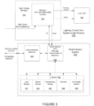
- Figure 11 shows a light fixture, according to another embodiment. This embodiment is similar to the embodiment of Figure 2 , but includes the controller 1135 of the light fixture 1102 managing the reception of beacons rather that transmission of beacons.
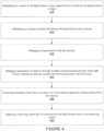
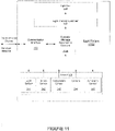
- Figure 13 is a flow chart that includes steps of a method of controlling a light fixture, according to another embodiment.
- a first step 1310 includes generating, by a sensor of the light fixture, a sense signal base on at least one of sensed motion or light.
- a second step 1320 includes maintaining a communications link between the light fixture and a network.
- a third step 1330 includes managing communication with the network.
- a fourth step 1340 includes managing manage reception of beacons through the wireless communication circuitry, wherein the beacons are received from an object, and the beacons include information associated with the object.
- a fifth step 1350 includes generating dimming control base on at least one of the sensed signal and communication from the network.
- a sixth step 1360 includes adjusting a dimming control line of a luminaire of the light fixture based on the dimming control.
- the information associated with the object includes at least one of a transmission power of the beacons, a unique ID of the object, or remaining battery power of the object.
- the light fixture is operative to determine a received signal strength indicator (RSSI) of the received beacons, wherein the information associated with the object includes at least transmission power of the beacons, and wherein the controller is operative to estimate a distance between the light fixture and the object based on the RSSI of the received beacons and the transmission power of the beacons.
- RSSI received signal strength indicator
- the information associated with the object includes sensed motion of the object, wherein the sensed motion includes sensed acceleration of the object.
- the sensed acceleration of the object influences a rate at which the object transmits the beacons.
- estimating a distance between the light fixture and the object based on an RSSI of the received beacons and a transmission power of the beacons, and estimating a location of the object based on the estimated distance.
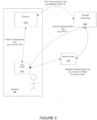
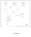
- Figure 14 shows a plurality of light fixtures 1410, 1411, 1412, 1413 that transmit beacons that are received by a device 1430, and the plurality of fixtures 1410, 1411, 1412, 1413 receive beacons that are transmitted by the device 1430, according to an embodiment.
- fixture 1410 transmits downlink (DL) beacons to the device 1430 and receives uplink (UL) beacons transmitted by the device 1430.
- Fixture 1411 transmits downlink (DL) beacons to the device 1430 and receives uplink (UL) beacons transmitted by the device 1430.
- Fixture 1413 transmits downlink (DL) beacons to the device 1430 and receives uplink (UL) beacons transmitted by the device 1430.
- Fixture 1412 transmits downlink (DL) beacons to the device 1430, but does not receive uplink (UL) beacons transmitted by the device 1430 because, for example, the device 1430 is too far away from the fixture 1412.
- the transmission power level of beacons transmitted in one direction may be more reliably received than beacons transmitted in the opposite direction.
- the beacons transmitted in the downlink direction may be more reliable than beacons transmitted in the uplink direction.
- At least some embodiments include adaptively determining which of the uplink and downlink beacons provide the better distance estimates, and adaptively calculating the distances accordingly. That is, one direction may be selected to be exclusively used for location determination, or the location determination may adaptively adjust how much of an influence either the uplink or downlink beacons have in the determination.
- the light fixtures 1410, 1411, 1412, 1413 are interfaced with a central of cloud controller or server 1475.
- the distance calculations are at least partially performed by the cloud server 1475.
Landscapes
- Engineering & Computer Science (AREA)
- Computer Networks & Wireless Communication (AREA)
- Physics & Mathematics (AREA)
- General Physics & Mathematics (AREA)
- Signal Processing (AREA)
- Remote Sensing (AREA)
- Radar, Positioning & Navigation (AREA)
- Multimedia (AREA)
- Health & Medical Sciences (AREA)
- Computing Systems (AREA)
- General Health & Medical Sciences (AREA)
- Medical Informatics (AREA)
- Circuit Arrangement For Electric Light Sources In General (AREA)
- Position Fixing By Use Of Radio Waves (AREA)
- Optical Communication System (AREA)
Claims (15)
- Appareil d'éclairage (202) comprenant :une unité de capteur (230) et un dispositif de commande d'intensité lumineuse (232) ;l'unité de capteur (230) comprenant :un capteur (241, 242, 243, 244, 245), le capteur pouvant être utilisé pour générer un signal de détection basé sur au moins un mouvement ou une lumière détectés ;un circuit de communication (250), le circuit de communication pouvant être utilisé pour maintenir une liaison avec un réseau ;un dispositif de commande (235), le dispositif de commande pouvant être utilisé pour :gérer la communication avec le réseau ;gérer la réception de balises au moyen du circuit de communication sans fil (250), les balises étant reçues à partir d'un objet, et les balises comprenant des informations associées à l'objet ;générer une commande de gradation basée sur au moins un élément parmi le signal détecté et la communication provenant du réseau ; et le dispositif de commande d'intensité lumineuse (232) étant configuré pour recevoir la commande de gradation et pouvant être utilisé pour ajuster une intensité lumineuse émise d'un luminaire (240) de l'appareil d'éclairage,les informations associées à l'objet comprenant au moins une puissance de transmission des balises,l'appareil d'éclairage (202) pouvant être utilisé pour déterminer un indicateur d'intensité de signal reçu, RSSI, des balises reçues, et le dispositif de commande (235) pouvant être utilisé pour estimer une distance entre l'appareil d'éclairage (202) et l'objet sur la base du RSSI des balises reçues et de la puissance de transmission des balises,et le RSSI de la balise reçue à un emplacement de l'objet étant comparé à une empreinte RSSI, l'empreinte RSSI comprenant des valeurs stockées de l'intensité de signal à des emplacements d'échantillonnage qui sont comparées au RSSI des balises reçues à l'emplacement de l'objet afin de trouver le meilleur emplacement correspondant.
- Appareil d'éclairage (202) selon la revendication 1, le RSSI à un emplacement donné stocké dans l'empreinte RSSI pouvant être mis à jour lorsque l'environnement change.
- Appareil d'éclairage (202) selon la revendication 2, la mise à jour du RSSI pouvant être effectuée à partir de données capturées lors du suivi d'un dispositif mobile.
- Appareil d'éclairage (202) selon la revendication 1, les informations associées à l'objet comprenant en outre un identifiant unique de l'objet, l'identifiant unique de l'objet permettant de filtrer les balises reçues.
- Appareil d'éclairage (202) selon la revendication 1, les informations associées à l'objet comprenant en outre le mouvement détecté de l'objet.
- Appareil d'éclairage (202) selon la revendication 5, le mouvement détecté comprenant l'accélération détectée de l'objet.
- Appareil d'éclairage (202) selon la revendication 6, l'accélération détectée comprenant une amplitude et une direction d'accélération de l'objet le long d'une ou plusieurs directions.
- Appareil d'éclairage (202) selon la revendication 7, le dispositif de commande pouvant être utilisé en outre pour détecter une orientation de l'objet au repos et une direction et une amplitude de mouvement de l'objet sur la base de l'amplitude et de la direction de l'accélération de l'objet le long d'une ou plusieurs directions.
- Appareil d'éclairage (202) selon la revendication 6, l'accélération détectée de l'objet influençant une vitesse à laquelle l'objet transmet les balises.
- Appareil d'éclairage (202) selon la revendication 1, les informations associées à l'objet comprenant au moins l'une des données du gyroscope, des données du magnétomètre, des données de température, des mesures de la qualité de l'air.
- Appareil d'éclairage (202) selon la revendication 1, le dispositif de commande pouvant être utilisé pour estimer une distance entre l'appareil d'éclairage (202) et l'objet sur la base d'un RSSI des balises reçues et d'une puissance de transmission des balises, et au moins un du dispositif de commande (235) et d'un autre dispositif de commande pouvant être utilisé pour estimer un emplacement de l'objet sur la base de la distance estimée.
- Appareil d'éclairage (202) selon la revendication 11, l'estimation de l'emplacement de l'objet étant en outre basée sur des données de mouvement détectées dans les balises.
- Appareil d'éclairage (202) selon la revendication 1, le dispositif de commande pouvant être utilisé en outre pour détecter le mouvement, et l'emplacement de l'objet étant déterminé seulement après avoir détecté le mouvement.
- Appareil d'éclairage (202) selon la revendication 1, un levier de puissance de transmission des balises à partir de l'objet étant limité en dessous d'un seuil.
- Procédé de fonctionnement d'un appareil d'éclairage (202) comprenant :la génération, par un capteur (241, 242, 243, 244, 245) de l'appareil d'éclairage (202), d'un signal de détection basé sur au moins un mouvement ou une lumière détectés ;le maintien d'un lien de communication entre l'appareil d'éclairage (202) et un réseau ;la gestion de la communication avec le réseau ;la gestion de la réception de balises à travers un circuit de communication sans fil (250), les balises étant reçues à partir d'un objet, et les balises comprenant des informations associées à l'objet ;la génération d'une commande de gradation basée sur au moins l'un du signal détecté et de la communication provenant du réseau ; etl'ajustement d'une ligne de commande de gradation d'un luminaire (240) de l'appareil d'éclairage (202) sur la base de la commande de gradation,les informations associées à l'objet comprenant au moins une puissance de transmission des balises,l'appareil d'éclairage (202) pouvant être utilisé pour déterminer un indicateur d'intensité de signal reçu, RSSI, des balises reçues, les informations associées à l'objet comprenant au moins une puissance de transmission des balises, et le dispositif de commande pouvant être utilisé pour estimer une distance entre l'appareil d'éclairage et l'objet sur la base du RSSI des balises reçues et de la puissance de transmission des balises,et le RSSI de la balise reçue à un emplacement de l'objet étant comparé à une empreinte RSSI, l'empreinte RSSI comprenant des valeurs stockées de l'intensité de signal à des emplacements d'échantillonnage qui sont comparées au RSSI des balises reçues à l'emplacement de l'objet afin de trouver le meilleur emplacement correspondant.
Applications Claiming Priority (3)
| Application Number | Priority Date | Filing Date | Title |
|---|---|---|---|
| US15/089,497 US9585227B2 (en) | 2009-09-05 | 2016-04-02 | Distributed light fixture beacon management |
| EP17776711.8A EP3437438B1 (fr) | 2016-04-02 | 2017-03-30 | Gestion de balise de luminaire distribué |
| PCT/US2017/025187 WO2017173170A1 (fr) | 2016-04-02 | 2017-03-30 | Gestion de balise de luminaire distribué |
Related Parent Applications (1)
| Application Number | Title | Priority Date | Filing Date |
|---|---|---|---|
| EP17776711.8A Division EP3437438B1 (fr) | 2016-04-02 | 2017-03-30 | Gestion de balise de luminaire distribué |
Publications (2)
| Publication Number | Publication Date |
|---|---|
| EP3832986A1 EP3832986A1 (fr) | 2021-06-09 |
| EP3832986B1 true EP3832986B1 (fr) | 2023-03-01 |
Family
ID=59966511
Family Applications (2)
| Application Number | Title | Priority Date | Filing Date |
|---|---|---|---|
| EP17776711.8A Active EP3437438B1 (fr) | 2016-04-02 | 2017-03-30 | Gestion de balise de luminaire distribué |
| EP20217863.8A Active EP3832986B1 (fr) | 2016-04-02 | 2017-03-30 | Gestion des balises d'appareils d'éclairage distribués |
Family Applications Before (1)
| Application Number | Title | Priority Date | Filing Date |
|---|---|---|---|
| EP17776711.8A Active EP3437438B1 (fr) | 2016-04-02 | 2017-03-30 | Gestion de balise de luminaire distribué |
Country Status (6)
| Country | Link |
|---|---|
| EP (2) | EP3437438B1 (fr) |
| JP (1) | JP6930999B2 (fr) |
| CN (2) | CN109644538A (fr) |
| AU (1) | AU2017241824B2 (fr) |
| SG (2) | SG10202100384UA (fr) |
| WO (1) | WO2017173170A1 (fr) |
Families Citing this family (5)
| Publication number | Priority date | Publication date | Assignee | Title |
|---|---|---|---|---|
| US11134556B2 (en) * | 2016-04-21 | 2021-09-28 | Signify Holding B.V. | Systems and methods for sensic device localization |
| FR3079316B1 (fr) * | 2018-03-23 | 2021-06-04 | Hager Controls | Procede de pilotage d'un dispositif domotique |
| JP7411917B2 (ja) * | 2021-11-11 | 2024-01-12 | パナソニックIpマネジメント株式会社 | 照明制御システム、照明負荷、決定装置、制御方法及びプログラム |
| CN114245525A (zh) * | 2021-11-16 | 2022-03-25 | 深圳市合信达控制系统有限公司 | 一种带夜灯的温控器 |
| CN117939757A (zh) * | 2024-03-25 | 2024-04-26 | 厦门普为光电科技有限公司 | 哨兵装置及包括此哨兵装置的照明系统 |
Family Cites Families (21)
| Publication number | Priority date | Publication date | Assignee | Title |
|---|---|---|---|---|
| JPH0965195A (ja) * | 1995-08-25 | 1997-03-07 | Fujitsu Ltd | 動き検出方法、動き検出装置及び動き検出撮像装置 |
| JP2002334793A (ja) * | 2001-05-08 | 2002-11-22 | Nec Corp | 照明灯点灯制御システム及び照明灯点灯制御方法 |
| US20030218537A1 (en) * | 2002-05-21 | 2003-11-27 | Lightspace Corporation | Interactive modular system |
| US6975614B2 (en) * | 2002-09-04 | 2005-12-13 | Harris Corporation | Intelligent communication node object beacon framework in a mobile ad hoc network |
| US9575478B2 (en) * | 2009-09-05 | 2017-02-21 | Enlighted, Inc. | Configuring a set of devices of a structure |
| US9345115B2 (en) * | 2009-09-05 | 2016-05-17 | Enlighted, Inc. | Distributed light fixture beacon transmission |
| KR101689887B1 (ko) * | 2010-07-09 | 2016-12-26 | 삼성전자주식회사 | 보행자의 보폭 추정 방법 및 이를 위한 휴대 단말 |
| US8532706B2 (en) * | 2010-10-30 | 2013-09-10 | Palm, Inc. | Techniques to manage a subscriber identity module for a mobile wireless device |
| US9287976B2 (en) * | 2011-07-26 | 2016-03-15 | Abl Ip Holding Llc | Independent beacon based light position system |
| KR20130116406A (ko) * | 2012-03-12 | 2013-10-24 | 한국전자통신연구원 | 가시광무선통신을 기반으로 한 led 조명 제어장치 및 그 방법 |
| WO2014018234A1 (fr) * | 2012-07-24 | 2014-01-30 | Enlighted, Inc. | Commande d'éclairage répartie |
| JP2014078398A (ja) * | 2012-10-10 | 2014-05-01 | Ricoh Co Ltd | 照明制御装置、照明制御システムおよびプログラム |
| US9544978B2 (en) * | 2012-11-30 | 2017-01-10 | Enlighted, Inc. | Beacon transmission of a fixture that includes sensed information |
| KR20140112918A (ko) * | 2013-03-14 | 2014-09-24 | 삼성전자주식회사 | 온도 및 습도를 이용한 화면 표시 제어 장치 및 방법 |
| US9210682B2 (en) * | 2013-04-15 | 2015-12-08 | Qualcomm Incorporated | Varying processes to control transmission characteristics for position determination operations |
| AU2014285027B2 (en) | 2013-07-03 | 2018-09-13 | Bright Light Systems, Inc. | Systems and methods for providing high-mast lighting |
| CN104023247B (zh) * | 2014-05-29 | 2015-07-29 | 腾讯科技(深圳)有限公司 | 获取、推送信息的方法和装置以及信息交互系统 |
| CA2952856A1 (fr) | 2014-06-18 | 2015-12-23 | Sensity Systems Inc. | Ossature d'application pour des reseaux de capteurs de lumiere interactifs |
| CN203916022U (zh) * | 2014-06-19 | 2014-11-05 | 青岛喵星信息科技有限公司 | 一种智能运动手镯 |
| WO2016026979A1 (fr) * | 2014-08-22 | 2016-02-25 | Philips Lighting Holding B.V. | Système de localisation comprenant de multiples balises et un système d'attribution |
| CN104869536B (zh) * | 2014-12-25 | 2018-10-16 | 清华大学 | 无线室内定位指纹地图的自动更新方法及装置 |
-
2017
- 2017-03-30 EP EP17776711.8A patent/EP3437438B1/fr active Active
- 2017-03-30 JP JP2018551786A patent/JP6930999B2/ja active Active
- 2017-03-30 CN CN201780030677.1A patent/CN109644538A/zh active Pending
- 2017-03-30 AU AU2017241824A patent/AU2017241824B2/en active Active
- 2017-03-30 SG SG10202100384UA patent/SG10202100384UA/en unknown
- 2017-03-30 SG SG11201808638VA patent/SG11201808638VA/en unknown
- 2017-03-30 CN CN202210712049.4A patent/CN115190676A/zh active Pending
- 2017-03-30 EP EP20217863.8A patent/EP3832986B1/fr active Active
- 2017-03-30 WO PCT/US2017/025187 patent/WO2017173170A1/fr active Application Filing
Also Published As
| Publication number | Publication date |
|---|---|
| JP6930999B2 (ja) | 2021-09-01 |
| AU2017241824A1 (en) | 2018-10-25 |
| EP3437438A1 (fr) | 2019-02-06 |
| SG10202100384UA (en) | 2021-02-25 |
| AU2017241824B2 (en) | 2021-05-27 |
| CN115190676A (zh) | 2022-10-14 |
| EP3437438B1 (fr) | 2021-01-13 |
| SG11201808638VA (en) | 2018-10-30 |
| JP2019511821A (ja) | 2019-04-25 |
| EP3437438A4 (fr) | 2019-07-31 |
| WO2017173170A1 (fr) | 2017-10-05 |
| CN109644538A (zh) | 2019-04-16 |
| EP3832986A1 (fr) | 2021-06-09 |
Similar Documents
| Publication | Publication Date | Title |
|---|---|---|
| US9585227B2 (en) | Distributed light fixture beacon management | |
| US10182487B2 (en) | Distributed fixture beacon management | |
| US9345115B2 (en) | Distributed light fixture beacon transmission | |
| US8994295B2 (en) | Commission of distributed light fixtures of a lighting system | |
| EP3832986B1 (fr) | Gestion des balises d'appareils d'éclairage distribués | |
| US10117308B2 (en) | Associating information with an asset or a physical space | |
| AU2017278675B2 (en) | Associating information with an asset or a physical space | |
| CA3012026C (fr) | Detection d'occupation et d'inoccupation dans le systeme d'eclairage | |
| US11105886B2 (en) | Three-dimensional asset tracking using radio frequency-enabled nodes | |
| CN109964515B (zh) | 用于定位系统的电子信标 | |
| US11170296B2 (en) | System level occupancy counting in a lighting system | |
| US20190220728A1 (en) | System level occupancy counting in a lighting system with a single transmitter and multiple receivers | |
| US20210314867A1 (en) | Extension of beacon operational life using integral photocell | |
| US11468333B2 (en) | System level occupancy counting in a lighting system with multiple transmitters and a single receiver | |
| US10477655B2 (en) | Lighting system with automatic beacon configuration |
Legal Events
| Date | Code | Title | Description |
|---|---|---|---|
| PUAI | Public reference made under article 153(3) epc to a published international application that has entered the european phase |
Free format text: ORIGINAL CODE: 0009012 |
|
| STAA | Information on the status of an ep patent application or granted ep patent |
Free format text: STATUS: THE APPLICATION HAS BEEN PUBLISHED |
|
| AC | Divisional application: reference to earlier application |
Ref document number: 3437438 Country of ref document: EP Kind code of ref document: P |
|
| AK | Designated contracting states |
Kind code of ref document: A1 Designated state(s): AL AT BE BG CH CY CZ DE DK EE ES FI FR GB GR HR HU IE IS IT LI LT LU LV MC MK MT NL NO PL PT RO RS SE SI SK SM TR |
|
| STAA | Information on the status of an ep patent application or granted ep patent |
Free format text: STATUS: REQUEST FOR EXAMINATION WAS MADE |
|
| 17P | Request for examination filed |
Effective date: 20210818 |
|
| RBV | Designated contracting states (corrected) |
Designated state(s): AL AT BE BG CH CY CZ DE DK EE ES FI FR GB GR HR HU IE IS IT LI LT LU LV MC MK MT NL NO PL PT RO RS SE SI SK SM TR |
|
| RAP3 | Party data changed (applicant data changed or rights of an application transferred) |
Owner name: ENLIGHTED INC. |
|
| RAP1 | Party data changed (applicant data changed or rights of an application transferred) |
Owner name: BUILDING ROBOTICS, INC. |
|
| REG | Reference to a national code |
Ref country code: DE Ref legal event code: R079 Ref document number: 602017066547 Country of ref document: DE Free format text: PREVIOUS MAIN CLASS: H04L0029080000 Ipc: H04L0067120000 |
|
| RIC1 | Information provided on ipc code assigned before grant |
Ipc: H04W 4/06 20090101ALI20220922BHEP Ipc: H04W 4/029 20180101ALI20220922BHEP Ipc: H04W 4/02 20180101ALI20220922BHEP Ipc: G08C 17/02 20060101ALI20220922BHEP Ipc: G01S 5/14 20060101ALI20220922BHEP Ipc: G01S 1/68 20060101ALI20220922BHEP Ipc: G01S 1/04 20060101ALI20220922BHEP Ipc: H04L 67/12 20220101AFI20220922BHEP |
|
| GRAP | Despatch of communication of intention to grant a patent |
Free format text: ORIGINAL CODE: EPIDOSNIGR1 |
|
| STAA | Information on the status of an ep patent application or granted ep patent |
Free format text: STATUS: GRANT OF PATENT IS INTENDED |
|
| INTG | Intention to grant announced |
Effective date: 20221116 |
|
| GRAS | Grant fee paid |
Free format text: ORIGINAL CODE: EPIDOSNIGR3 |
|
| GRAA | (expected) grant |
Free format text: ORIGINAL CODE: 0009210 |
|
| STAA | Information on the status of an ep patent application or granted ep patent |
Free format text: STATUS: THE PATENT HAS BEEN GRANTED |
|
| AC | Divisional application: reference to earlier application |
Ref document number: 3437438 Country of ref document: EP Kind code of ref document: P |
|
| AK | Designated contracting states |
Kind code of ref document: B1 Designated state(s): AL AT BE BG CH CY CZ DE DK EE ES FI FR GB GR HR HU IE IS IT LI LT LU LV MC MK MT NL NO PL PT RO RS SE SI SK SM TR |
|
| REG | Reference to a national code |
Ref country code: GB Ref legal event code: FG4D |
|
| REG | Reference to a national code |
Ref country code: CH Ref legal event code: EP Ref country code: AT Ref legal event code: REF Ref document number: 1551806 Country of ref document: AT Kind code of ref document: T Effective date: 20230315 |
|
| REG | Reference to a national code |
Ref country code: DE Ref legal event code: R096 Ref document number: 602017066547 Country of ref document: DE |
|
| REG | Reference to a national code |
Ref country code: IE Ref legal event code: FG4D |
|
| REG | Reference to a national code |
Ref country code: LT Ref legal event code: MG9D |
|
| REG | Reference to a national code |
Ref country code: NL Ref legal event code: MP Effective date: 20230301 |
|
| PG25 | Lapsed in a contracting state [announced via postgrant information from national office to epo] |
Ref country code: RS Free format text: LAPSE BECAUSE OF FAILURE TO SUBMIT A TRANSLATION OF THE DESCRIPTION OR TO PAY THE FEE WITHIN THE PRESCRIBED TIME-LIMIT Effective date: 20230301 Ref country code: NO Free format text: LAPSE BECAUSE OF FAILURE TO SUBMIT A TRANSLATION OF THE DESCRIPTION OR TO PAY THE FEE WITHIN THE PRESCRIBED TIME-LIMIT Effective date: 20230601 Ref country code: LV Free format text: LAPSE BECAUSE OF FAILURE TO SUBMIT A TRANSLATION OF THE DESCRIPTION OR TO PAY THE FEE WITHIN THE PRESCRIBED TIME-LIMIT Effective date: 20230301 Ref country code: LT Free format text: LAPSE BECAUSE OF FAILURE TO SUBMIT A TRANSLATION OF THE DESCRIPTION OR TO PAY THE FEE WITHIN THE PRESCRIBED TIME-LIMIT Effective date: 20230301 Ref country code: HR Free format text: LAPSE BECAUSE OF FAILURE TO SUBMIT A TRANSLATION OF THE DESCRIPTION OR TO PAY THE FEE WITHIN THE PRESCRIBED TIME-LIMIT Effective date: 20230301 Ref country code: ES Free format text: LAPSE BECAUSE OF FAILURE TO SUBMIT A TRANSLATION OF THE DESCRIPTION OR TO PAY THE FEE WITHIN THE PRESCRIBED TIME-LIMIT Effective date: 20230301 |
|
| PGFP | Annual fee paid to national office [announced via postgrant information from national office to epo] |
Ref country code: DE Payment date: 20230519 Year of fee payment: 7 Ref country code: CH Payment date: 20230613 Year of fee payment: 7 |
|
| REG | Reference to a national code |
Ref country code: AT Ref legal event code: MK05 Ref document number: 1551806 Country of ref document: AT Kind code of ref document: T Effective date: 20230301 |
|
| PG25 | Lapsed in a contracting state [announced via postgrant information from national office to epo] |
Ref country code: SE Free format text: LAPSE BECAUSE OF FAILURE TO SUBMIT A TRANSLATION OF THE DESCRIPTION OR TO PAY THE FEE WITHIN THE PRESCRIBED TIME-LIMIT Effective date: 20230301 Ref country code: PL Free format text: LAPSE BECAUSE OF FAILURE TO SUBMIT A TRANSLATION OF THE DESCRIPTION OR TO PAY THE FEE WITHIN THE PRESCRIBED TIME-LIMIT Effective date: 20230301 Ref country code: NL Free format text: LAPSE BECAUSE OF FAILURE TO SUBMIT A TRANSLATION OF THE DESCRIPTION OR TO PAY THE FEE WITHIN THE PRESCRIBED TIME-LIMIT Effective date: 20230301 Ref country code: GR Free format text: LAPSE BECAUSE OF FAILURE TO SUBMIT A TRANSLATION OF THE DESCRIPTION OR TO PAY THE FEE WITHIN THE PRESCRIBED TIME-LIMIT Effective date: 20230602 Ref country code: FI Free format text: LAPSE BECAUSE OF FAILURE TO SUBMIT A TRANSLATION OF THE DESCRIPTION OR TO PAY THE FEE WITHIN THE PRESCRIBED TIME-LIMIT Effective date: 20230301 |
|
| PG25 | Lapsed in a contracting state [announced via postgrant information from national office to epo] |
Ref country code: SM Free format text: LAPSE BECAUSE OF FAILURE TO SUBMIT A TRANSLATION OF THE DESCRIPTION OR TO PAY THE FEE WITHIN THE PRESCRIBED TIME-LIMIT Effective date: 20230301 Ref country code: RO Free format text: LAPSE BECAUSE OF FAILURE TO SUBMIT A TRANSLATION OF THE DESCRIPTION OR TO PAY THE FEE WITHIN THE PRESCRIBED TIME-LIMIT Effective date: 20230301 Ref country code: PT Free format text: LAPSE BECAUSE OF FAILURE TO SUBMIT A TRANSLATION OF THE DESCRIPTION OR TO PAY THE FEE WITHIN THE PRESCRIBED TIME-LIMIT Effective date: 20230703 Ref country code: EE Free format text: LAPSE BECAUSE OF FAILURE TO SUBMIT A TRANSLATION OF THE DESCRIPTION OR TO PAY THE FEE WITHIN THE PRESCRIBED TIME-LIMIT Effective date: 20230301 Ref country code: CZ Free format text: LAPSE BECAUSE OF FAILURE TO SUBMIT A TRANSLATION OF THE DESCRIPTION OR TO PAY THE FEE WITHIN THE PRESCRIBED TIME-LIMIT Effective date: 20230301 Ref country code: AT Free format text: LAPSE BECAUSE OF FAILURE TO SUBMIT A TRANSLATION OF THE DESCRIPTION OR TO PAY THE FEE WITHIN THE PRESCRIBED TIME-LIMIT Effective date: 20230301 |
|
| PGFP | Annual fee paid to national office [announced via postgrant information from national office to epo] |
Ref country code: GB Payment date: 20230403 Year of fee payment: 7 |
|
| PG25 | Lapsed in a contracting state [announced via postgrant information from national office to epo] |
Ref country code: SK Free format text: LAPSE BECAUSE OF FAILURE TO SUBMIT A TRANSLATION OF THE DESCRIPTION OR TO PAY THE FEE WITHIN THE PRESCRIBED TIME-LIMIT Effective date: 20230301 Ref country code: IS Free format text: LAPSE BECAUSE OF FAILURE TO SUBMIT A TRANSLATION OF THE DESCRIPTION OR TO PAY THE FEE WITHIN THE PRESCRIBED TIME-LIMIT Effective date: 20230701 |
|
| REG | Reference to a national code |
Ref country code: BE Ref legal event code: MM Effective date: 20230331 |
|
| REG | Reference to a national code |
Ref country code: DE Ref legal event code: R097 Ref document number: 602017066547 Country of ref document: DE |
|
| PG25 | Lapsed in a contracting state [announced via postgrant information from national office to epo] |
Ref country code: LU Free format text: LAPSE BECAUSE OF NON-PAYMENT OF DUE FEES Effective date: 20230330 |
|
| PLBE | No opposition filed within time limit |
Free format text: ORIGINAL CODE: 0009261 |
|
| STAA | Information on the status of an ep patent application or granted ep patent |
Free format text: STATUS: NO OPPOSITION FILED WITHIN TIME LIMIT |
|
| PG25 | Lapsed in a contracting state [announced via postgrant information from national office to epo] |
Ref country code: MC Free format text: LAPSE BECAUSE OF FAILURE TO SUBMIT A TRANSLATION OF THE DESCRIPTION OR TO PAY THE FEE WITHIN THE PRESCRIBED TIME-LIMIT Effective date: 20230301 |
|
| REG | Reference to a national code |
Ref country code: IE Ref legal event code: MM4A |
|
| PG25 | Lapsed in a contracting state [announced via postgrant information from national office to epo] |
Ref country code: SI Free format text: LAPSE BECAUSE OF FAILURE TO SUBMIT A TRANSLATION OF THE DESCRIPTION OR TO PAY THE FEE WITHIN THE PRESCRIBED TIME-LIMIT Effective date: 20230301 Ref country code: MC Free format text: LAPSE BECAUSE OF FAILURE TO SUBMIT A TRANSLATION OF THE DESCRIPTION OR TO PAY THE FEE WITHIN THE PRESCRIBED TIME-LIMIT Effective date: 20230301 Ref country code: IE Free format text: LAPSE BECAUSE OF NON-PAYMENT OF DUE FEES Effective date: 20230330 Ref country code: FR Free format text: LAPSE BECAUSE OF NON-PAYMENT OF DUE FEES Effective date: 20230501 Ref country code: DK Free format text: LAPSE BECAUSE OF FAILURE TO SUBMIT A TRANSLATION OF THE DESCRIPTION OR TO PAY THE FEE WITHIN THE PRESCRIBED TIME-LIMIT Effective date: 20230301 |
|
| 26N | No opposition filed |
Effective date: 20231204 |
|
| PG25 | Lapsed in a contracting state [announced via postgrant information from national office to epo] |
Ref country code: BE Free format text: LAPSE BECAUSE OF NON-PAYMENT OF DUE FEES Effective date: 20230331 |