EP3832912B1 - Antenna calibration method and device - Google Patents
Antenna calibration method and device Download PDFInfo
- Publication number
- EP3832912B1 EP3832912B1 EP19844459.8A EP19844459A EP3832912B1 EP 3832912 B1 EP3832912 B1 EP 3832912B1 EP 19844459 A EP19844459 A EP 19844459A EP 3832912 B1 EP3832912 B1 EP 3832912B1
- Authority
- EP
- European Patent Office
- Prior art keywords
- transmission
- beam direction
- transmission channel
- calibration signal
- gain
- Prior art date
- Legal status (The legal status is an assumption and is not a legal conclusion. Google has not performed a legal analysis and makes no representation as to the accuracy of the status listed.)
- Active
Links
Images



Classifications
-
- H—ELECTRICITY
- H04—ELECTRIC COMMUNICATION TECHNIQUE
- H04B—TRANSMISSION
- H04B7/00—Radio transmission systems, i.e. using radiation field
- H04B7/02—Diversity systems; Multi-antenna system, i.e. transmission or reception using multiple antennas
- H04B7/04—Diversity systems; Multi-antenna system, i.e. transmission or reception using multiple antennas using two or more spaced independent antennas
- H04B7/08—Diversity systems; Multi-antenna system, i.e. transmission or reception using multiple antennas using two or more spaced independent antennas at the receiving station
- H04B7/0891—Space-time diversity
- H04B7/0897—Space-time diversity using beamforming per multi-path, e.g. to cope with different directions of arrival [DOA] at different multi-paths
-
- H—ELECTRICITY
- H01—ELECTRIC ELEMENTS
- H01Q—ANTENNAS, i.e. RADIO AERIALS
- H01Q3/00—Arrangements for changing or varying the orientation or the shape of the directional pattern of the waves radiated from an antenna or antenna system
- H01Q3/26—Arrangements for changing or varying the orientation or the shape of the directional pattern of the waves radiated from an antenna or antenna system varying the relative phase or relative amplitude of energisation between two or more active radiating elements; varying the distribution of energy across a radiating aperture
- H01Q3/267—Phased-array testing or checking devices
-
- G—PHYSICS
- G01—MEASURING; TESTING
- G01R—MEASURING ELECTRIC VARIABLES; MEASURING MAGNETIC VARIABLES
- G01R29/00—Arrangements for measuring or indicating electric quantities not covered by groups G01R19/00 - G01R27/00
- G01R29/08—Measuring electromagnetic field characteristics
- G01R29/10—Radiation diagrams of antennas
-
- H—ELECTRICITY
- H04—ELECTRIC COMMUNICATION TECHNIQUE
- H04B—TRANSMISSION
- H04B17/00—Monitoring; Testing
- H04B17/10—Monitoring; Testing of transmitters
- H04B17/11—Monitoring; Testing of transmitters for calibration
- H04B17/12—Monitoring; Testing of transmitters for calibration of transmit antennas, e.g. of the amplitude or phase
-
- H—ELECTRICITY
- H04—ELECTRIC COMMUNICATION TECHNIQUE
- H04B—TRANSMISSION
- H04B17/00—Monitoring; Testing
- H04B17/20—Monitoring; Testing of receivers
- H04B17/21—Monitoring; Testing of receivers for calibration; for correcting measurements
- H04B17/22—Monitoring; Testing of receivers for calibration; for correcting measurements for calibration of the receiver components
- H04B17/221—Monitoring; Testing of receivers for calibration; for correcting measurements for calibration of the receiver components of receiver antennas, e.g. as to amplitude or phase
-
- H—ELECTRICITY
- H04—ELECTRIC COMMUNICATION TECHNIQUE
- H04B—TRANSMISSION
- H04B17/00—Monitoring; Testing
- H04B17/20—Monitoring; Testing of receivers
- H04B17/29—Performance testing
- H04B17/295—Detection of non-compliance or faulty performance, e.g. response deviations
-
- H—ELECTRICITY
- H04—ELECTRIC COMMUNICATION TECHNIQUE
- H04B—TRANSMISSION
- H04B7/00—Radio transmission systems, i.e. using radiation field
- H04B7/02—Diversity systems; Multi-antenna system, i.e. transmission or reception using multiple antennas
- H04B7/04—Diversity systems; Multi-antenna system, i.e. transmission or reception using multiple antennas using two or more spaced independent antennas
- H04B7/06—Diversity systems; Multi-antenna system, i.e. transmission or reception using multiple antennas using two or more spaced independent antennas at the transmitting station
- H04B7/0613—Diversity systems; Multi-antenna system, i.e. transmission or reception using multiple antennas using two or more spaced independent antennas at the transmitting station using simultaneous transmission
- H04B7/0615—Diversity systems; Multi-antenna system, i.e. transmission or reception using multiple antennas using two or more spaced independent antennas at the transmitting station using simultaneous transmission of weighted versions of same signal
- H04B7/0617—Diversity systems; Multi-antenna system, i.e. transmission or reception using multiple antennas using two or more spaced independent antennas at the transmitting station using simultaneous transmission of weighted versions of same signal for beam forming
-
- H—ELECTRICITY
- H04—ELECTRIC COMMUNICATION TECHNIQUE
- H04B—TRANSMISSION
- H04B7/00—Radio transmission systems, i.e. using radiation field
- H04B7/02—Diversity systems; Multi-antenna system, i.e. transmission or reception using multiple antennas
- H04B7/04—Diversity systems; Multi-antenna system, i.e. transmission or reception using multiple antennas using two or more spaced independent antennas
- H04B7/06—Diversity systems; Multi-antenna system, i.e. transmission or reception using multiple antennas using two or more spaced independent antennas at the transmitting station
- H04B7/0613—Diversity systems; Multi-antenna system, i.e. transmission or reception using multiple antennas using two or more spaced independent antennas at the transmitting station using simultaneous transmission
- H04B7/0615—Diversity systems; Multi-antenna system, i.e. transmission or reception using multiple antennas using two or more spaced independent antennas at the transmitting station using simultaneous transmission of weighted versions of same signal
- H04B7/0619—Diversity systems; Multi-antenna system, i.e. transmission or reception using multiple antennas using two or more spaced independent antennas at the transmitting station using simultaneous transmission of weighted versions of same signal using feedback from receiving side
- H04B7/0621—Feedback content
- H04B7/0634—Antenna weights or vector/matrix coefficients
-
- H—ELECTRICITY
- H04—ELECTRIC COMMUNICATION TECHNIQUE
- H04B—TRANSMISSION
- H04B7/00—Radio transmission systems, i.e. using radiation field
- H04B7/02—Diversity systems; Multi-antenna system, i.e. transmission or reception using multiple antennas
- H04B7/04—Diversity systems; Multi-antenna system, i.e. transmission or reception using multiple antennas using two or more spaced independent antennas
- H04B7/06—Diversity systems; Multi-antenna system, i.e. transmission or reception using multiple antennas using two or more spaced independent antennas at the transmitting station
- H04B7/0613—Diversity systems; Multi-antenna system, i.e. transmission or reception using multiple antennas using two or more spaced independent antennas at the transmitting station using simultaneous transmission
- H04B7/0682—Diversity systems; Multi-antenna system, i.e. transmission or reception using multiple antennas using two or more spaced independent antennas at the transmitting station using simultaneous transmission using phase diversity (e.g. phase sweeping)
-
- H—ELECTRICITY
- H04—ELECTRIC COMMUNICATION TECHNIQUE
- H04B—TRANSMISSION
- H04B7/00—Radio transmission systems, i.e. using radiation field
- H04B7/02—Diversity systems; Multi-antenna system, i.e. transmission or reception using multiple antennas
- H04B7/04—Diversity systems; Multi-antenna system, i.e. transmission or reception using multiple antennas using two or more spaced independent antennas
- H04B7/08—Diversity systems; Multi-antenna system, i.e. transmission or reception using multiple antennas using two or more spaced independent antennas at the receiving station
- H04B7/0837—Diversity systems; Multi-antenna system, i.e. transmission or reception using multiple antennas using two or more spaced independent antennas at the receiving station using pre-detection combining
- H04B7/0842—Weighted combining
- H04B7/086—Weighted combining using weights depending on external parameters, e.g. direction of arrival [DOA], predetermined weights or beamforming
-
- H—ELECTRICITY
- H04—ELECTRIC COMMUNICATION TECHNIQUE
- H04B—TRANSMISSION
- H04B7/00—Radio transmission systems, i.e. using radiation field
- H04B7/02—Diversity systems; Multi-antenna system, i.e. transmission or reception using multiple antennas
- H04B7/04—Diversity systems; Multi-antenna system, i.e. transmission or reception using multiple antennas using two or more spaced independent antennas
- H04B7/08—Diversity systems; Multi-antenna system, i.e. transmission or reception using multiple antennas using two or more spaced independent antennas at the receiving station
- H04B7/0882—Diversity systems; Multi-antenna system, i.e. transmission or reception using multiple antennas using two or more spaced independent antennas at the receiving station using post-detection diversity
Definitions
- the present disclosure relates to the technical field of wireless communications, and more particularly relates to a method and an apparatus for calibrating an antenna.
- a large-scale active antenna array technology is a key enabling technology for 5G communications, which ensures the consistency of the amplitudes and phases of respective active channels and is a prerequisite for the effective realization of an array beamforming function.
- the large-scale active antenna array technology has become a key enabling technology.
- calibration often needs to be performed under a closed anechoic chamber environment, and a single-tone signal (a signal with a single frequency) is generally used to complete a calibration test.
- a single-tone signal (a signal with a single frequency) is generally used to complete a calibration test.
- large-scale active antenna arrays need to switch test frequency points in a dark room for calibration testing, which is costly and is not suitable for production and factory calibration.
- OTA over-the-airtechnology
- a prior right document discloses an array antenna calibration method and device, which is used for calibrating an array antenna in real time in an open calibration environment.
- Said method comprises: determining, on the basis of a preset direction angle of each preset beam direction, an initial beam weight vector matrix of an array antenna to be calibrated, and emitting, by means of a test antenna in a standard beam direction, a first calibration signal to the array antenna to be calibrated; determining, on the basis of the first calibration signal received by each channel of the array antenna to be calibrated, a magnitude-phase error between the first calibration signal received by means of a center channel and the first calibration signal received by means of each channel; and using the magnitude-phase error to calibrate the initial beam weight vector matrix, so as to obtain a compensation beam weight vector matrix.
- the beam forming of an array antenna can be effectively detected in an open scenario, so as to calibrate the magnitude-phase error of each channel of the array antenna.
- a document discloses a method for performing beamforming.
- the method includes initiating a first signal transmitted from a target second device to be received by a first device having an antenna array.
- a first beamforming weight matrix is generated by the first device that automatically corrects amplitude and phase errors of the antenna array and maximizes antenna gain toward the target second device using a covariance matrix derived from the received first signal.
- An enhanced second beamforming weight matrix is then generated by the first device using a mask window or a jointly optimized algorithm to further suppress interference to and from other active second devices.
- the enhancement is computed and applied based on the distribution of multiple active second devices.
- the antenna array is steered using the second beamforming weight matrix to transmit to and receive from the target second device with an optimized antenna beam pattern.
- the embodiments of the present disclosure provide a method and an apparatus for calibrating an antenna.
- F -1 [] represents fourier inverse transform
- [ ⁇ ] T represents matrix transposition operation
- K represents the number of single-frequency signal components included in a signal
- f k represents the frequency of the kth single-frequency signal component
- s ( f k ) represents a frequency spectrum of the kth single-frequency signal component
- the dimension of a ( ⁇ , ⁇ ,f k ) is N ⁇ 1 that represents an amplitude and phase response of the kth single-frequency signal component and used to be called an array guide vector of a signal
- the dimension of n(t) is N ⁇ 1 that represents a noise vector of an array and is generally supposed to be additive white gaussian noise for the convenience of analysis.
- a ( ⁇ , ⁇ ,f k ) is recorded to be a k ( ⁇ , ⁇ ).
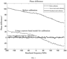
- FIG. 1 illustrates phase difference characteristics of two channels before and after a large-scale antenna array system uses a narrow-band model for calibration under a 400 MHz working bandwidth. It can be seen that only the phase difference at a center frequency point is relatively small, and the phase difference at an edge frequency point of the working bandwidth is relatively large.
- [ ⁇ ] H represents a conjugate transpose operation; and the beamforming gain may be expressed by
- the embodiments of the present disclosure provide a method for calibrating an antenna which may perform multi-channel broadband calibration for a large-scale active antenna array.
- the method compensates, based on a test environment of an OTA, an amplitude and phase error of a channel antenna within a relatively large frequency bandwidth range.
- the full line in FIG. 1 represents a phase difference characteristic of two channels after the calibration method according to the embodiments of the present disclosure is used for calibration.
- the method according to the embodiments of the present disclosure can keep amplitude and phase differences of channels consistent within the working bandwidth of the whole system, thereby effectively ensuring a beamforming effect of the large-scale antenna array for a large-bandwidth signal and ensuring the effectiveness and integrity of a forming function of a device during production detection.
- a phase difference between channels is mainly composed of two parts: the first part is that a channel difference causes an initial phase difference of the center frequency point, i.e., a phase difference compensated by a narrow-band calibration model; and the second part is that a frequency bandwidth causes a phase difference varying with phases, and the phase difference can be effectively compensated through a broadband calibration model.
- the embodiments of the present disclosure compensate and calibrate the amplitude and phase differences of the channels in two parts.
- An initial phase difference corresponding to the center frequency point is compensated to an original theoretical beam weight table, and a phase difference caused by a signal frequency bandwidth is calibrated and compensated via amplitude and phase equalization of a single channel.
- a calibration environment is built at first based on a production scene of a device; an active antenna array is then calibrated under the built calibration environment.
- a production environment of the device may be appropriately transformed to make an electromagnetic environment relatively stable and meet a far field test condition, thereby obtaining the calibration environment used in the embodiments of the present disclosure.
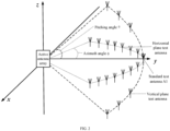
- FIG. 2 exemplarily shows a calibration environment used in the embodiments of the present disclosure.
- the calibration environment includes an active antenna array to be tested, and also includes a test antenna used for calibrating the active antenna array. A distance between the test antenna and the active antenna array meets the far field test condition.
- the test antenna may also be replaced by a terminal.
- the embodiments of the present disclosure are described by taking the test antenna as an example.
- a reception channel beam weight matrix W of the active antenna array includes beam weight vectors corresponding to a plurality of received beam directions (i.e., a plurality of direction angles).
- the beam weight vector of one received beam direction includes beam weights of N reception channels corresponding to the one received beam direction.
- N is the number of the reception channels of the active antenna array, and N is an integer greater than 1.
- test antennas are placed on the X-Y horizontal plane, and correspond to 14 azimuth angles; and 6 test antennas are placed on the Y-Z vertical plane, and correspond to 6 pitching angles.
- One test antenna corresponds to one beam direction region, and one beam direction region corresponds to one direction angle.
- the direction angle is the direction angle of the corresponding test antenna.
- a reception channel initial beam weight matrix may be formed based on active antenna array characteristics.
- q is an integer, 1 ⁇ q ⁇ Q ;
- Q represents the number of received beam directions in the reception channel beam weight matrix, and
- w ( ⁇ q , ⁇ q ) represents a beam weight vector corresponding to the qth received beam direction.
- w ( ⁇ 1 , ⁇ 1 ) represents a beam weight vector corresponding to the received beam direction 1
- w ( ⁇ 2 , ⁇ 2 ) represents a beam weight vector corresponding to the beam direction 2
- the rest can be done in the same manner.
- the dimension number of the beam weight vector w ( ⁇ q , ⁇ q ) in the reception channel initial beam weight matrix W indicates the number of channels.
- FIG. 3 it is a schematic diagram of a reception channel calibration flow for an active antenna array not in accordance with the invention.
- a sequence of a reception calibration signal may be generated at first.
- the reception calibration signal is transmitted by a test antenna to the active antenna array for calibrating the reception channels of the active antenna array.
- F ⁇ ⁇ ⁇ represents fast fourier transform
- F ⁇ 1 ⁇ ⁇ ⁇ represents inverse fast fourier transform
- the flow may include the following.
- the active antenna array receives a reception calibration signal transmitted by a test antenna from a reference beam direction, obtains an amplitude and phase error of each reception channel in the active antenna array, and updates a reception channel beam weight matrix according to the amplitude and phase error of each reception channel.
- N is the number of the reception channels of the active antenna array
- x n ( t ) in the received signal matrix x ( t ) represents the baseband data received by the nth reception channel.
- the amplitudes and the phases between the data (i.e., the above-mentioned N pieces of data) received by the respective reception channels in the active antenna array shall be completely consistent.
- a difference value is a reception channel amplitude and phase error corresponding to the reference beam direction.
- h n E s t x n ⁇ t E x n t x n ⁇ t
- the active antenna array performs multi-channel amplitude and phase error compensation on the reception channel beam weight matrix to obtain an updated reception channel beam weight matrix:
- ⁇ represents a point multiplication operation of respective elements in a vector.
- the active antenna array performs, according to the updated reception channel beam weight matrix, beamforming on the reception calibration signal of the reference beam direction to obtain a reception channel beam gain corresponding to the reference beam direction.
- the active antenna array receives a reception calibration signal transmitted by a test antenna in a first beam direction region, and uses, according to a direction angle of the reception calibration signal from the first beam direction region, a beam weight vector corresponding to the direction angle in the reception channel beam weight matrix to perform beamforming on the reception calibration signal from the first beam direction region to obtain a reception channel beam gain corresponding to the first beam direction region.
- the "first beam direction region” may be any beam region in L beam regions obtained by division.
- the direction angle corresponding to the first beam direction region is different from a direction angle corresponding to the reference beam direction.
- G RXl represents the reception channel beam gain corresponding to the lth beam region
- w ⁇ RX H ⁇ l ⁇ l represents the beam weight vector corresponding to the direction angle ( ⁇ l , ⁇ l ) in the reception channel weight matrix.
- the active antenna array determines a difference value between the reception channel beam gain corresponding to the first beam direction region and the reception channel beam gain corresponding to the reference beam direction, and proceeds to S306 if the difference value is greater than a set gain error threshold, otherwise, proceeds to S305.
- the gain error threshold may be preset.
- the value of the gain error threshold may be determined according to a requirement for the calibration accuracy. If the calibration accuracy is higher, the gain error threshold is smaller.
- the active antenna array determines that the calibration for the beam weight vector corresponding to the first beam direction region in the reception channel beam weight matrix is completed.
- the difference value between the reception channel beam gain corresponding to the first beam region and the reception channel beam gain corresponding to the reference beam direction is less than the set gain error threshold at S304, it is indicated that a reception channel error of the active antenna array is relatively small in all received beam directions corresponding to the first beam direction region, so that the reception beam weight vector corresponding to the first beam direction region in the reception channel beam weight matrix may be kept unchanged, that is, there is no need to perform error calibration for the reception channels in the received beam directions corresponding to the first beam direction region.
- the active antenna array performs at most K reception channel calibration iteration processes, so as to update the beam weight vector, corresponding to the direction angle of the reception calibration signal that is from the first beam direction region, in the reception channel beam weight matrix, thereby realizing calibration for the reception channels of the active antenna array in the received beam directions corresponding to the first beam direction region.
- the reception channel calibration iteration process may refer to FIG. 4 .
- the reception channels of the active antenna array may be all calibrated according to S303 to S306 in the foregoing flow, thereby realizing the calibration for the reception channels of the active antenna array in all the received beam directions.
- FIG. 4 it is a flow diagram of a reception channel calibration iteration process not in accordance with the invention. As shown in the figure, the flow may include the following.
- the active antenna array obtains, according to the reception calibration signal from the first beam direction region, an amplitude and phase error vector of N reception channels of the active antenna array in the first beam direction region.
- the lth beam direction region is taken as an example.
- the active antenna array updates, according to the amplitude and phase error determined in the current iteration process, a received beam weight vector in a received beam direction in the first beam direction region in the reception channel beam weight matrix.
- the lth beam direction region is taken as an example.
- the direction angle of the reception calibration signal of the test antenna from the lth beam direction region is ( ⁇ l , ⁇ l ) .
- the lth beam direction region corresponds to all received beam directions in the following direction angle range: the azimuth angle range is ⁇ l ⁇ P 2 , ⁇ l + P 2 , and the pitching angle range is ⁇ l ⁇ P 2 , ⁇ l + P 2 , where P is the step size.
- the active antenna array updates, according to the amplitude and phase error vector determined in the current iteration process, the beam weight vectors of all the received beams in the direction angle range in the reception beam weight matrix.
- the beam weight vector of beam l i is expressed as w ⁇ l i ⁇ l i .
- the active antenna array uses, according to the direction angle of the reception calibration signal from the first beam direction region, the updated beam weight vector of the corresponding direction angle in the reception channel beam weight matrix to perform beamforming on the reception calibration signal from the first beam direction region to obtain a reception channel beam gain corresponding to the first beam direction region.
- S404 The active antenna array determines whether a gain error between the reception channel beam gain determined in the current iteration process and the reception channel beam gain corresponding to the reference beam direction is greater than a gain error threshold, and proceeds to S406 if the gain error is greater than the gain error threshold, otherwise, S405 is executed.
- S406 It is determined whether the maximum number of iterations has been reached; S407 is executed if the maximum number of iterations has been reached, otherwise, S408 is executed.
- S408 The active antenna array receives a reception calibration signal from the first beam direction region, and S401 is executed to perform the next iteration process.
- a scenario shown in FIG. 2 is taken as an example.
- the active antenna array determines, according to S303 to S304 in FIG. 3 , whether to update the several beam weight vectors within the direction angle range of ( ⁇ , ⁇ ) ⁇ [ ⁇ l -2.5°, ⁇ l +2.5°] ⁇ [ ⁇ l -2.5°, ⁇ l +2.5°] corresponding to this direction angle; and executes, according to the flow shown in FIG.
- a reception channel calibration iteration process if updating is needed until the several beam weight vectors in the direction angle range of ( ⁇ , ⁇ ) ⁇ [ ⁇ l -2.5°, ⁇ l +2.5°] ⁇ [ ⁇ l - 2.5°, ⁇ l +2.5°] are completely updated, or until the updating fails. If updating is not needed, the several beam weight vectors in the direction angle range of ( ⁇ , ⁇ ) ⁇ [ ⁇ l -2.5°, ⁇ l +2.5°] ⁇ [ ⁇ l -2.5° , ⁇ l +2.5°] are kept unchanged.
- reception calibration signals are transmitted in sequence through the corresponding test antennas; and the reception calibration signal transmitted by each test antenna is processed according to the processing flow of reception channel calibration for the calibration signal transmitted by the test antenna 1 until the reception channel calibration is completed for all the beam direction regions.
- the reception calibration signal in the reference beam direction is used to initially update the reception channel beam weight matrix, that is, to initially calibrate the reception channels; then, the beam weight vectors in a plurality of beam directions in a corresponding beam direction region range are updated respectively for different beam direction regions, so as to regionally update the beam weight vectors corresponding to the corresponding regions in the reception channel beam weight matrix, that is, to regionally calibrate the reception channels.
- the method for calibrating the reception channel By adopting the method for calibrating the reception channel according to the above embodiments of the present disclosure, the beamforming functions of related devices of a large-scale active antenna array can be calibrated and detected under a production environment. Compared with the prior art, the method for calibrating the reception channel mainly has the following several advantages.
- the method for calibrating the reception channel according to the embodiments of the present disclosure performs limited detection in vertical and horizontal spatial dimensions only, so that the production detection efficiency is improved.
- the method for calibrating the reception channel according to the embodiments of the present disclosure is independent of a transmission channel calibration process, and can compensate an amplitude-phase error between a transmission channel and a reception channel and improve the beamforming functionality.
- the method for calibrating the reception channel according to the embodiments of the present disclosure is convenient for algorithm realization, and is favorable for being used in an actual production environment.
- the embodiments of the present disclosure also provide a method for calibrating transmission channels for an active antenna array.
- a transmission channel calibration process and the reception channel calibration process of the active antenna array may use the same calibration environment.
- a building method for the calibration environment may refer to the foregoing embodiment, and no more repeated descriptions will be provided here.
- a transmission channel beam weight matrix W of the active antenna array includes beam weight vectors corresponding to a plurality of transmitted beam directions (i.e., a plurality of direction angles).
- the beam weight vector of one transmitted beam direction includes beam weights of N transmission channels corresponding to the one transmitted beam direction.
- N is the number of the transmission channels of the active antenna array, and N is an integer greater than 1.
- a space range corresponding to the Q transmitted beam directions may be divided into L (L is an integer greater than 1, L ⁇ Q) beam direction regions according to the placement positions and the number of the test antennas.
- Each beam direction region corresponds to at least one beam direction
- at least one beam direction region in the L beam direction regions corresponds to a plurality of beam directions.
- the active antenna array may store a correspondence between each beam direction region and the transmitted beam directions.
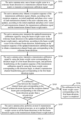
- FIG. 5 it is a schematic diagram of a transmission channel calibration flow for an active antenna array according to the embodiment of the present disclosure.
- a sequence of a transmission calibration signal may be generated at first.
- the transmission calibration signal is transmitted by the active antenna array to a test antenna to calibrate the transmission channels of the active antenna array.
- F[ ⁇ ] represents fast fourier transform
- F -1 [ ⁇ ] represents inverse fast fourier transform
- the flow may include the following.
- the active antenna array uses a beam weight vector in a reference beam direction in the transmission channel beam weight matrix to transmit a transmission calibration signal.
- the active antenna array obtains a reception sequence of the transmission calibration signal, obtains, according to the reception sequence, an initial amplitude and phase error vector of each transmission channel in the active antenna array, and updates, according to the initial amplitude and phase error vector of each transmission channel, the transmission calibration signal and the transmission channel beam weight matrix.
- the process of performing the synchronization and time-frequency domain transformation processing and transmitting the processed frequency domain calibration sequence to the active antenna array may be executed by the test antenna, or executed by other devices. The embodiments of the present disclosure do not limit this.
- An updated time domain sequence of each transmission channel is obtained through inverse fourier transform.
- the active antenna array transmits the updated transmission calibration signal by using the beam weight vector in the reference beam direction in the updated transmission channel beam weight matrix, and performs, according to the beam weight vector in the reference beam direction in the transmission channel beam weight matrix, beamforming on the reception sequence of the updated transmission calibration signal to obtain a transmission channel beam gain corresponding to the reference beam direction.
- the active antenna array transmits the updated transmission calibration signal at the rated nominal power P TX 0 by using the beam weight vector w ⁇ TX (0°,0°), and the time domain sequence of the transmission calibration signal of each transmission channel is s 1 AC , s 2 AC , ... , s N AC .
- the time domain sequence used as a reception sequence of the transmission calibration signal is returned to the active antenna array.
- the active antenna array transmits a transmission calibration signal by using the beam weight vector corresponding to a direction angle of a first beam direction region, and performs beamforming on the reception sequence of the transmission calibration signal by using the beam weight vector corresponding to the direction angle in the transmission channel beam weight matrix, to obtain a transmission channel beamforming gain corresponding to the first beam direction region.
- the "first beam direction region” may be any beam region in L beam regions obtained by division.
- the direction angle corresponding to the first beam direction region is different from a direction angle corresponding to the reference beam direction.
- the lth beam region is taken as an example.
- the active antenna array transmits the updated transmission calibration signal by using the beam weight vector w ⁇ TX ( ⁇ l , ⁇ l ) corresponding to the direction angle ( ⁇ l , ⁇ l ).
- the test antenna corresponding to the direction angle ( ⁇ l , ⁇ l ) receives the transmission calibration signal, and the time domain sequence of the transmission calibration signal received by the test antenna is x TX l t .
- the time domain sequence used as an end sequence of the transmission calibration signal is transmitted to the active antenna array.
- the active antenna array performs beamforming on x TX l t by using the beam weight vector w ⁇ TX ( ⁇ l , ⁇ l ) corresponding to the direction angle ( ⁇ l , ⁇ l ) according to the reception sequence x TX l t of the transmission calibration signal, to obtain a reception channel beam gain corresponding to the lth beam region:
- G TXl 10 log 10 E w ⁇ TX H ⁇ l ⁇ l x TX l t 2 P TX 0
- G TXl represents the transmission channel beam gain corresponding to the lth beam region
- w ⁇ TX H ⁇ l ⁇ l represents the beam weight vector in the direction angle ( ⁇ l , ⁇ l ) in the reception channel weight matrix.
- the test antenna 1 receives the transmission calibration signal, and the time domain sequence of the transmission calibration signal received by the test antenna 1 is transmitted to the active antenna array.
- the active antenna array determines a difference value between the transmission channel beam gain corresponding to the first beam direction region and the transmission channel beam gain corresponding to the reference beam direction, and proceeds to S506 if the difference value is less than or equal to a set gain error threshold, otherwise, proceeds to S507.
- the gain error threshold may be preset.
- the value of the gain error threshold may be determined according to a requirement for the calibration accuracy. If the calibration accuracy is higher, the gain error threshold is smaller.
- the active antenna array determines that the calibration for the beam weight vector corresponding to the first beam direction region in the transmission channel beam weight matrix is completed.
- the difference value between the transmission channel beam gain corresponding to the first beam region and the transmission channel beam gain corresponding to the reference beam direction is less than the set gain error threshold at S505, it is indicated that a transmission channel error of the active antenna array in all transmitted beam directions corresponding to the first beam direction region is relatively small, so that all the beam weight vectors corresponding to the first beam direction region in the transmission channel beam weight matrix may be kept unchanged, that is, there is no need to perform error calibration for the reception channels in the beam directions corresponding to the first beam direction region.
- the active antenna array performs at most K transmission channel calibration iteration processes, so as to update the beam weight vectors in all beam directions in the first beam direction region in the transmission channel beam weight matrix, thereby realizing calibration for the transmission channels of the active antenna array in the beam directions corresponding to the first beam direction region.
- the transmission channel calibration iteration process may refer to FIG. 6 .
- the transmission channels of the active antenna array may be all calibrated according to S504 to S507 in the foregoing flow, thereby realizing the calibration for the transmission channels of the active antenna array in all the transmitted beam directions.
- FIG. 6 it is a flow diagram of a transmission channel calibration iteration process according to the embodiment of the present disclosure. As shown in the figure, the flow may include the following.
- the active antenna array obtains, according to the reception sequence of the transmission calibration signal transmitted by using the beam weight vector corresponding to the direction angle in the first beam direction region, an amplitude and phase error vector of the N transmission channels of the active antenna array in the first beam direction region.
- the lth beam direction region is taken as an example.
- the active antenna array updates, according to the amplitude and phase error vector determined in the current iteration process, the transmission calibration signal and the beam weight vector in the beam direction in the first beam direction region in the transmission channel beam weight matrix.
- the active antenna array may update, according to the formula (22), the transmission calibration signal.
- the time domain sequence of the updated transmission calibration signal of each transmission channel is s 1 ACl , s 2 ACl , ... , s N ACl . Since the first beam direction region corresponds to the beam weight vectors in a plurality of beam directions in the transmission channel beam weight matrix, the active antenna array updates the beam weight vectors in all the beam directions corresponding to the first beam direction region.
- the lth beam direction region is taken as an example, and the direction angle corresponding the lth beam direction region is ( ⁇ l , ⁇ l ) .
- the beam direction region corresponds to all the beam directions in the following direction angle range: the azimuth angle range is ⁇ l ⁇ P 2 , ⁇ l + P 2 , and the pitching angle range is ⁇ l ⁇ P 2 , ⁇ l + P 2 , where P is the step size.
- the active antenna array updates, according to the amplitude and phase error vector determined in the current iteration process, the beam weight vectors in all the beam directions in the direction angle range in the transmission channel beam weight matrix.
- the beam weight vector of beam l i is expressed as w ⁇ l i ⁇ l i .
- the beam weight vector of each beam direction in the direction angle range is updated.
- the active antenna array transmits the updated transmission calibration signal by using the beam weight vector corresponding to the direction angle of the first beam direction region, and performs beamforming on the reception sequence of the transmission calibration signal by using the updated beam weight vector corresponding to the direction angle in the transmission channel beam weight matrix, to obtain a transmission channel beamforming gain corresponding to the first beam direction region.
- the active antenna array determines whether a gain error between the transmission channel beam gain determined in the current iteration process and a transmission beamforming gain corresponding to the reference beam direction is greater than a gain error threshold, and proceeds to S605 if the gain error is less than or equal to the gain error threshold, otherwise, proceeds to S606.
- S606 It is determined whether the maximum number of iterations has been reached; and S607 is executed if the maximum number of iterations has been reached.
- the active antenna array transmits a transmission calibration signal by using the beam weight vector of the direction angle corresponding to the first beam direction region, and obtains a reception sequence of the transmission calibration signal, and proceeds to S601 to enter the next iteration process.
- a scenario shown in FIG. 2 is taken as an example.
- the active antenna array determines, according to S503 to S504 in FIG. 5 , whether to update the several beam weight vectors within the direction angle range of ( ⁇ , ⁇ ) ⁇ [ ⁇ l -2.5°, ⁇ l +2.5°] ⁇ [ ⁇ l - 2.5° , ⁇ l +2.5°] corresponding to this direction angle, and executes, according to the flow shown in FIG.
- a transmission channel calibration iteration process if updating is needed until the several beam weight vectors in the direction angle range of ( ⁇ , ⁇ ) ⁇ [ ⁇ l -2.5°, ⁇ l +2.5°] ⁇ [ ⁇ l - 2.5°, ⁇ l +2.5°] are completely updated, or until the updating fails. If updating is not needed, the several beam weight vectors in the direction angle range of ( ⁇ , ⁇ ) ⁇ [ ⁇ l -2.5°, ⁇ l +2.5°] ⁇ [ ⁇ l -2.5°, ⁇ l +2.5°] are kept unchanged.
- the beam weight vectors corresponding to the direction angles of the corresponding beam direction regions are used to transmit transmission calibration signals in sequence; and according to the reception sequence of the transmission calibration signal, the transmission calibration signal is processed according to the transmission channel calibration flow for the beam direction region 1 in the above flow until the transmission channel calibration is completed for all the beam direction regions.
- the reception sequence of the transmission calibration signal in the reference beam direction is used to initially update the transmission channel beam weight matrix, that is, to initially calibrate the transmission channels; and then, the beam weight vectors in a plurality of beam directions in a corresponding beam direction region range are updated respectively for different beam direction regions, so as to regionally update the beam weight vectors corresponding to the corresponding regions in the transmission channel beam weight matrix, that is, to regionally calibrate the transmission channels.
- the method for calibrating the transmission channel By adopting the method for calibrating the transmission channel according to the above embodiments of the present disclosure, the beamforming functions of related devices of a large-scale active antenna array can be calibrated and detected under a production environment. Compared with the prior art, the method for calibrating the transmission channel mainly has the following several advantages.
- the method for calibrating the transmission channel according to the embodiments of the present disclosure does not need to be carried out in an anechoic chamber, so that the requirement standard and a heavy investment for a test site are lowered.
- the method for calibrating the transmission channel according to the embodiments of the present disclosure performs limited detection in vertical and horizontal spatial dimensions only, so that the production detection efficiency is improved.
- the method for calibrating the transmission channel according to the embodiments of the present disclosure is independent of a reception channel calibration process, and can compensate an amplitude-phase error between a transmission channel and a reception channel and improve the beamforming functionality.
- the method for calibrating the transmission channel according to the embodiments of the present disclosure is convenient for algorithm realization, and is favorable for being used in an actual production environment.
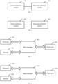
- the embodiments of the present disclosure also provide an apparatus for calibrating an antenna used for calibrating reception channels of an active antenna array.
- FIG. 7 it is a schematic structural diagram of an apparatus for calibrating an antenna used for realizing reception channel calibration not in accordance with the invention.
- the apparatus is applied to an active antenna array.
- a received beam direction range corresponding to a reception channel beam weight matrix of the active antenna array is divided into a plurality of beam direction regions; and one beam direction region corresponds to at least one received beam direction, and at least one beam direction region corresponds to a plurality of received beam directions.
- both an azimuth angle and a pitching angle of the reference beam direction are zero.
- the direction angle of the reference beam direction is different from an azimuth angle corresponding to any beam direction region.
- the apparatus may include: an initial calibration module 701 and a regional calibration module 702
- the initial calibration module 701 is configured to obtain, according to a reception calibration signal received by the active antenna array from the reference beam direction, an initial amplitude and phase error vector of N reception channels of the active antenna array in the reference beam direction, update, according to the initial amplitude and phase error vector, a beam weight vector in each beam direction in the reception channel beam weight matrix, and perform, according to the updated beam weight vector in the reference beam direction in the reception channel beam weight matrix, beamforming on the reception calibration signal in the reference beam direction to obtain a first reception channel beam gain corresponding to the reference beam direction, where the beam weight vector of one received beam direction includes beam weights of the N reception channels corresponding to the one received beam direction, and N is an integer greater than 1.
- the regional calibration module 702 is configured to perform beamforming on a reception calibration signal in a first beam direction region by using a beam weight vector in a corresponding direction angle in the reception channel beam weight matrix according to the reception calibration signal received by the active antenna array from the first beam direction region and a direction angle corresponding to the first beam direction region, to obtain a second reception channel beam gain corresponding to the first beam direction region; and if a gain error between the second reception channel beam gain and the first reception channel beam gain is greater than a gain error threshold, perform at most K reception channel calibration iteration processes according to the reception calibration signal from the first beam direction region, where K is the maximum number of iterations, and the first beam direction region is one of the plurality of beam direction regions.
- the regional calibration module 702 executes:
- the embodiments of the present disclosure also provide an antenna calibration apparatus used for calibrating transmission channels of an active antenna array.
- FIG. 8 it is a schematic structural diagram of an apparatus for calibrating an antenna used for realizing transmission channel calibration according to the embodiment of the present disclosure.
- the apparatus is applied to an active antenna array.
- a transmitted beam direction range corresponding to a transmission channel beam weight matrix of the active antenna array is divided into a plurality of beam direction regions; and one beam direction region corresponds to at least one transmitted beam direction, and at least one beam direction region corresponds to a plurality of transmitted beam directions.
- both an azimuth angle and a pitching angle of the reference beam direction are zero.
- the direction angle of the reference beam direction is different from an azimuth angle corresponding to any beam direction region.
- the apparatus may include: an initial calibration module 801 and a regional calibration module 802.
- the initial calibration module 801 is configured to: obtain an initial amplitude and phase error vector of N transmission channels of the active antenna array according to a reception sequence of a transmission calibration signal transmitted by the active antenna array by using a beam weight vector in a reference beam direction in the transmission channel beam weight matrix, update, according to the initial amplitude and phase error vector, the transmission calibration signal and the beam weight vector in each beam direction in the transmission channel beam weight matrix, transmit the updated transmission calibration signal by using the updated beam weight vector of the reference beam direction in the transmission channel beam weight matrix, and perform, according to the beam weight vector in the reference beam direction, beamforming on the reception sequence of the updated transmission calibration signal to obtain a first transmission channel beam gain corresponding to the reference beam direction, where a beam weight vector of one transmitted beam direction includes beam weights of the N transmission channels corresponding to the one transmitted beam direction, and N is an integer greater than 1.
- the regional calibration module 802 is configured to: after the active antenna array transmits a transmission calibration signal by using a beam weight vector corresponding to a direction angle of a first beam direction region, perform beamforming on a reception sequence of the transmitted transmission calibration signal by using the beam weight vector of the corresponding direction angle in the transmission channel beam weight matrix to obtain a second transmission channel beam gain corresponding to the first beam direction region; and if a gain error between the second transmission channel beam gain and the first transmission channel beam gain is greater than a gain error threshold, perform at most K transmission channel calibration iteration processes, where K is the maximum number of iterations, and the first beam direction region is one of the plurality of beam direction regions.
- the regional calibration module 802 executes:
- the embodiments of the present disclosure also provide a communication apparatus.
- the communication apparatus can realize the reception channel calibration flow in the foregoing embodiment.
- the communication apparatus may include: a processor 901, a memory 902, a transceiver 903 and a bus interface 904.
- the processor 901 is responsible for managing the bus architecture and performing usual processing, and the memory 902 may store data used when the processor 901 performs operations.
- the transceiver 903 is configured to receive and transmit data under the control of the processor 901.
- a bus architecture may include any number of interconnected buses and bridges, and is particularly formed by linking one or more of processors represented by the processor 901 and the various circuits of memories represented by the memory 902 together.
- the bus architecture may also link various other circuits such as peripherals, voltage regulators and power management circuits, which are well known in the art and, therefore, will not be further described herein.
- a bus interface 904 provides an interface.
- the processor 901 is responsible for managing the bus architecture and performing usual processing, and the memory 902 may store data used when the processor 901 performs operations.
- a flow disclosed by the embodiment of the present disclosure may be applied to the processor 901, or implemented by the processor 901.
- each step of a signal processing flow may be completed by integrated logic circuits of hardware in the processor 901 or instructions in the form of software.
- the processor 901 may be a general-purpose processor, a digital signal processor, an application specific integrated circuit, a field programmable gate array or other programmable logic device, a discrete gate or transistor logic device, and a discrete hardware component, and may implement or execute the various methods, steps and logic block diagrams disclosed in the embodiments of the present disclosure.
- the general-purpose processor may be a microprocessor or any conventional processor.
- the steps of the method disclosed in conjunction with the embodiment of the present disclosure may be directly embodied as being executed by a hardware processor, or may be executed and completed by a combination of hardware and software modules in the processor.
- the software module may be located in a mature storage medium in the art, such as a random access memory, a flash memory, a read-only memory, a programmable read-only memory, an electrically erasable programmable memory, and a register.
- the storage medium is located in the memory 902, and the processor 901 reads information in the memory 902 and completes the steps of the signal processing flow in combination with its hardware.
- the processor 901 is used for reading programs in the memory 902 to execute the reception channel calibration flow described in the foregoing embodiments.
- the specific implementation of the flow may refer to the related descriptions of the foregoing embodiments, and no more repeated descriptions will be provided here.
- the embodiments of the present disclosure also provide a communication apparatus.
- the communication apparatus can realize the transmission channel calibration flow in the foregoing embodiment.
- the communication apparatus may include: a processor 1001, a memory 1002, a transceiver 1003 and a bus interface 1004.
- the processor 1001 is responsible for managing the bus architecture and performing usual processing, and the memory 1002 may store data used when the processor 1001 performs operations.
- the transceiver 1003 is configured to receive and transmit data under the control of the processor 1001.
- a bus architecture may include any number of interconnected buses and bridges, and is particularly formed by linking one or more of processors represented by the processor 1001 and the various circuits of memories represented by the memory 1002 together.
- the bus architecture may also link various other circuits such as peripherals, voltage regulators and power management circuits, which are well known in the art and, therefore, will not be further described herein.
- a bus interface 1004 provides an interface.
- the processor 1001 is responsible for managing the bus architecture and performing usual processing, and the memory 1002 may store data used when the processor 1001 performs operations.
- a flow disclosed by the embodiment of the present disclosure may be applied to the processor 1001, or implemented by the processor 1001.
- each step of a signal processing flow may be completed by integrated logic circuits of hardware in the processor 1001 or instructions in the form of software.
- the processor 1001 may be a general-purpose processor, a digital signal processor, an application specific integrated circuit, a field programmable gate array or other programmable logic device, a discrete gate or transistor logic device, and a discrete hardware component, and may implement or execute the various methods, steps and logic block diagrams disclosed in the embodiments of the present disclosure.
- the general-purpose processor may be a microprocessor or any conventional processor.
- the steps of the method disclosed in conjunction with the embodiment of the present disclosure may be directly embodied as being executed by a hardware processor, or may be executed and completed by a combination of hardware and software modules in the processor.
- the software module may be located in a mature storage medium in the art, such as a random access memory, a flash memory, a read-only memory, a programmable read-only memory, an electrically erasable programmable memory, and a register.
- the storage medium is located in the memory 1002, and the processor 1001 reads information in the memory 1002 and completes the steps of the signal processing flow in combination with its hardware.
- the processor 1001 is used for reading programs in the memory 1002 to execute the transmission channel calibration flow described in the foregoing embodiments.
- the specific implementation of the flow may refer to the related descriptions of the foregoing embodiments, and no more repeated descriptions will be provided here.
- the embodiments of the present disclosure further provide a computer-readable storage medium.
- the computer-readable storage medium stores computer-executable instructions.
- the computer-executable instructions are configured to cause a computer to execute the flows executed in the foregoing embodiments.
- These computer program instructions may also be stored in a computer readable memory capable of guiding the computer or other programmable data processing devices to work in a specific manner, thereby making the instructions that are stored in the computer readable memory generate manufactured products that include instruction apparatuses.
- the instruction apparatuses realize the specified functions in one or multiple flows of the flow diagrams and/or one or multiple blocks of the block diagrams.
- These computer program instructions also may be loaded onto the computer or other programmable data processing devices to execute a series of operation steps on the computer or other programmable data processing devices to generate computer implemented processing, so that the instructions executed on the computer or other programmable data processing devices provide steps for realizing the specified functions in one or multiple flows of the flow diagrams and/or one or multiple blocks of the block diagrams.
Landscapes
- Engineering & Computer Science (AREA)
- Computer Networks & Wireless Communication (AREA)
- Signal Processing (AREA)
- Physics & Mathematics (AREA)
- Electromagnetism (AREA)
- General Physics & Mathematics (AREA)
- Mathematical Physics (AREA)
- Variable-Direction Aerials And Aerial Arrays (AREA)
- Radio Transmission System (AREA)
Description
- This application claims priority to
China Patent Application No. 201810872421.1, filed on August 02, 2018 - The present disclosure relates to the technical field of wireless communications, and more particularly relates to a method and an apparatus for calibrating an antenna.
- A large-scale active antenna array technology is a key enabling technology for 5G communications, which ensures the consistency of the amplitudes and phases of respective active channels and is a prerequisite for the effective realization of an array beamforming function.
- In the 5G communication era, the large-scale active antenna array technology has become a key enabling technology. For the amplitude and phase calibration and beamforming function verification of an existing large-scale active antenna array system, calibration often needs to be performed under a closed anechoic chamber environment, and a single-tone signal (a signal with a single frequency) is generally used to complete a calibration test. Under an application background that a 5G communication system covers a larger bandwidth, large-scale active antenna arrays need to switch test frequency points in a dark room for calibration testing, which is costly and is not suitable for production and factory calibration. For the production and manufacturing process, there is no better solution for how to carry out rapid calibration test of the system.
- Existing testing for calibration and beamforming functions and other functions of a large-scale active antenna array system can only be carried out in a closed anechoic chamber. The test is costly and high in calibration cost. Generally, this is only suitable for laboratory tests in research and development procedures, and cannot be applied to a manufacturing environment of productized production. In addition, an existing over-the-airtechnology (OTA) calibration test solution is generally single-frequency-point calibration test, which is low in test efficiency, and due to the multiplexing of antenna transmission and reception, the OTA calibration generally also performs the same compensation for transmission and reception, without considering that amplitude and phase differences on transmission and reception channel analog links will produce certain errors and affect the beamforming performance.
- A prior right document (
WO 2019/047831 A1 ) discloses an array antenna calibration method and device, which is used for calibrating an array antenna in real time in an open calibration environment. Said method comprises: determining, on the basis of a preset direction angle of each preset beam direction, an initial beam weight vector matrix of an array antenna to be calibrated, and emitting, by means of a test antenna in a standard beam direction, a first calibration signal to the array antenna to be calibrated; determining, on the basis of the first calibration signal received by each channel of the array antenna to be calibrated, a magnitude-phase error between the first calibration signal received by means of a center channel and the first calibration signal received by means of each channel; and using the magnitude-phase error to calibrate the initial beam weight vector matrix, so as to obtain a compensation beam weight vector matrix. In this way, the beam forming of an array antenna can be effectively detected in an open scenario, so as to calibrate the magnitude-phase error of each channel of the array antenna. - A document (
US 9967081 B2 - The embodiments of the present disclosure provide a method and an apparatus for calibrating an antenna.
- The invention is defined by the appended independent claims. Dependent claims constitute embodiments of the invention.
-
-
FIG. 1 is a comparative schematic diagram of antenna calibration between the prior art and the embodiment of the present disclosure. -
FIG. 2 is a schematic diagram of an antenna calibration environment in the embodiment of the present disclosure. -
FIG. 3 is a schematic diagram of a reception channel calibration flow not in accordance with the invention. -
FIG. 4 is a flow diagram of a reception channel calibration iteration process in a reception channel calibration flow not in accordance with the invention. -
FIG. 5 is a schematic diagram of a transmission channel calibration flow according to the embodiment of the present disclosure. -
FIG. 6 is a flow diagram of a transmission channel calibration iteration process in a transmission channel calibration flow according to the embodiment of the present disclosure. -
FIG. 7 is a schematic structural diagram of an apparatus for calibrating an antenna used for realizing reception channel calibration not in accordance with the invention. -
FIG. 8 is a schematic structural diagram of an apparatus for calibrating an antenna used for realizing transmission channel calibration according to the embodiment of the present disclosure. -
FIG. 9 is a schematic structural diagram of a communication apparatus according to the embodiments of the present disclosure. -
FIG. 10 is a schematic structural diagram of a communication apparatus according to other embodiments of the present disclosure. - Reception models of an N-channel large-scale active antenna array for bandwidth signals s(t) for an azimuth angle ϕ and a pitching angle θ can be expressed by the following formulas:


- F -1[] represents fourier inverse transform; [·] T represents matrix transposition operation; K represents the number of single-frequency signal components included in a signal; fk represents the frequency of the kth single-frequency signal component; s(fk ) represents a frequency spectrum of the kth single-frequency signal component; the dimension of a (θ,ϕ,fk ) is N×1 that represents an amplitude and phase response of the kth single-frequency signal component and used to be called an array guide vector of a signal; and the dimension of n(t) is N×1 that represents a noise vector of an array and is generally supposed to be additive white gaussian noise for the convenience of analysis. For the convenience of expression of the formulas, a(θ,ϕ,fk ) is recorded to be a k (θ,ϕ). When a signal is a narrow-band signal, i.e., when K in the formula (1) is equal to 1, f0 represents a center carrier frequency of the signal, and the formula (1) is transformed into:

- The existing beamforming is generally performing, based on a narrow-band model shown by the formula (3), phase adjustment of a corresponding beam position on each channel, that is, a beam weight vector is set to be w = a 0(θ,ϕ).
- An absolute signal bandwidth used in a 5G communication system is much greater than a signal bandwidth used in a conventional communication system.
FIG. 1 illustrates phase difference characteristics of two channels before and after a large-scale antenna array system uses a narrow-band model for calibration under a 400 MHz working bandwidth. It can be seen that only the phase difference at a center frequency point is relatively small, and the phase difference at an edge frequency point of the working bandwidth is relatively large. [·] H represents a conjugate transpose operation; and the beamforming gain may be expressed by | w H a (θ,ϕ)|l|wHw|. Due to | w H a k (θ,ϕ)|<| w H a 0(θ,ϕ)|, fk ≠ f 0, the beamforming gain may be greatly affected. - The embodiments of the present disclosure provide a method for calibrating an antenna which may perform multi-channel broadband calibration for a large-scale active antenna array. The method compensates, based on a test environment of an OTA, an amplitude and phase error of a channel antenna within a relatively large frequency bandwidth range. The full line in
FIG. 1 represents a phase difference characteristic of two channels after the calibration method according to the embodiments of the present disclosure is used for calibration. Compared with single-tone calibration, the method according to the embodiments of the present disclosure can keep amplitude and phase differences of channels consistent within the working bandwidth of the whole system, thereby effectively ensuring a beamforming effect of the large-scale antenna array for a large-bandwidth signal and ensuring the effectiveness and integrity of a forming function of a device during production detection. - It can be found from the comparison, shown in
FIG. 1 , of the phase difference characteristics before and after the calibration that a phase difference between channels is mainly composed of two parts: the first part is that a channel difference causes an initial phase difference of the center frequency point, i.e., a phase difference compensated by a narrow-band calibration model; and the second part is that a frequency bandwidth causes a phase difference varying with phases, and the phase difference can be effectively compensated through a broadband calibration model. - The embodiments of the present disclosure compensate and calibrate the amplitude and phase differences of the channels in two parts. An initial phase difference corresponding to the center frequency point is compensated to an original theoretical beam weight table, and a phase difference caused by a signal frequency bandwidth is calibrated and compensated via amplitude and phase equalization of a single channel.
- The embodiments of the present disclosure are described in detail below in combination with the drawings.
- In the embodiments of the present disclosure, a calibration environment is built at first based on a production scene of a device; an active antenna array is then calibrated under the built calibration environment.
- Optionally, a production environment of the device may be appropriately transformed to make an electromagnetic environment relatively stable and meet a far field test condition, thereby obtaining the calibration environment used in the embodiments of the present disclosure.
-
FIG. 2 exemplarily shows a calibration environment used in the embodiments of the present disclosure. As shown inFIG. 2 , the calibration environment includes an active antenna array to be tested, and also includes a test antenna used for calibrating the active antenna array. A distance between the test antenna and the active antenna array meets the far field test condition. The test antenna may also be replaced by a terminal. The embodiments of the present disclosure are described by taking the test antenna as an example. - There may be a plurality of test antennas, and the plurality of test antennas may be placed at different positions on different planes. The test antennas connected by dash-dotted lines in
FIG. 2 are placed on a horizontal plane (such as an X-Y plane in the figure), and the test antennas connected by dotted lines are placed on a vertical plane (such as a Y-Z plane in the figure). A direction angle of a test antenna may be expressed by an azimuth angle ϕ on the horizontal plane and a pitching angle θ on the vertical plane. - A reception channel beam weight matrix W of the active antenna array includes beam weight vectors corresponding to a plurality of received beam directions (i.e., a plurality of direction angles). The beam weight vector of one received beam direction includes beam weights of N reception channels corresponding to the one received beam direction. N is the number of the reception channels of the active antenna array, and N is an integer greater than 1.
- Supposing that the reception channel beam weight matrix W includes beam weight vectors corresponding to Q (Q is an integer greater than 1) received beam directions (i.e., Q direction angles), a space range corresponding to the Q received beam directions may be divided into L (L is an integer greater than 1, L<Q) beam direction regions according to the placement positions and the number of the test antennas. Each beam direction region corresponds to at least one beam direction, and at least one beam direction region in the L beam direction regions corresponds to a plurality of received beam directions. The active antenna array may store a correspondence between each beam direction region and the received beam directions.
- For example, if a total range of the received beam directions corresponding to the reception channel beam weight matrix W is that: in case of an azimuth angle range ϕ ∈[-35°,35°] of a horizontal direction, a pitching angle range θ ∈[-15°,15°] of a vertical direction, and the received beam direction taking 0.5° as a step size, the reception channel beam weight matrix W includes 200 received beam directions. As shown in
FIG. 2 , one test antenna 0 (i.e., a standard test antenna A1 in the figure) placed at the position at the azimuth angle ϕq = 0° and the pitching angle θq = 0° is used as a test antenna corresponding to a reference beam direction. Taking 0.5° as a step size, 14 test antennas are placed on the X-Y horizontal plane, and correspond to 14 azimuth angles; and 6 test antennas are placed on the Y-Z vertical plane, and correspond to 6 pitching angles. In this way, the whole direction angle range corresponding to Q=200 received beam directions can be divided into 20 beam direction regions, i.e., L=20. One test antenna corresponds to one beam direction region, and one beam direction region corresponds to one direction angle. The direction angle is the direction angle of the corresponding test antenna. The direction angle of a signal transmitted by the test antenna located in the beam direction region l is (θl , ϕl ), and this beam direction region corresponds to all received beam directions in the following direction angle range: the azimuth angle range is

- For example, the direction angle of the
test antenna 1 inFIG. 2 is (ϕ 1 = 5°, θ 1 = 0°), the azimuth angle range of the corresponding beam region is [2.5° , 7.5°], and the pitching angle range of the corresponding beam region is [-2.5° ,2.5°]. That is, all the received beam directions in the direction angle range correspond to this region. - Before the active antenna array is calibrated, a reception channel initial beam weight matrix may be formed based on active antenna array characteristics. The reception channel initial beam weight matrix may be expressed as:

- Where q is an integer, 1 ≤ q ≤ Q; Q represents the number of received beam directions in the reception channel beam weight matrix, and w (θq ,ϕq ) represents a beam weight vector corresponding to the qth received beam direction. For example, w (θ 1 ,ϕ 1) represents a beam weight vector corresponding to the received
beam direction 1, and w (θ 2 ,ϕ2 ) represents a beam weight vector corresponding to the beam direction 2, and the rest can be done in the same manner. - The dimension number of the beam weight vector w (θq,ϕq ) in the reception channel initial beam weight matrix W indicates the number of channels.
- Theoretically, there is:

- That is, theoretically, for a terminal (test antenna) having both the azimuth angle and the pitching angle being zero, its beam weight vector is a vector of full 1, and beamforming realizes data addition operation of channels.
- Before calibration, the reception channel beam weight matrix of the active antenna array is represented as WRX = W . That is, before the calibration, the reception channel beam weight matrix of the active antenna array is set to be the same as the initial beam weight matrix W.
- Referring to
FIG. 3 , it is a schematic diagram of a reception channel calibration flow for an active antenna array not in accordance with the invention. - Before the reception channels are calibrated, a sequence of a reception calibration signal may be generated at first. The reception calibration signal is transmitted by a test antenna to the active antenna array for calibrating the reception channels of the active antenna array.
- During specific implementation, a frequency domain sequence SRX (k), k = 1,2,···K of the reception calibration signal and a time domain sequence sRX (m) , m = 1,2,···M of the reception calibration signal may be generated according to a working bandwidth BW of the system.
- A transformation relation between the time domain sequence and the frequency domain sequence of the reception calibration signal is:


- Where


- In order to realize simplicity and convenience of operation of the fast fourier transform for the time domain and the frequency domain in the process of realizing calibration, the length of the time domain sequence of the calibration signal may be set to be M = 2 floor[log
2 K]+1. Due to K<M, the frequency domain sequence SRX (k) of the reception calibration signal needs to be zero-padded to a length M. - As shown in the
FIG. 3 , the flow may include the following. - S301: The active antenna array receives a reception calibration signal transmitted by a test antenna from a reference beam direction, obtains an amplitude and phase error of each reception channel in the active antenna array, and updates a reception channel beam weight matrix according to the amplitude and phase error of each reception channel.
- The reference beam direction may correspond to a direction angle (θq = 0°, ϕq = 0°), and the direction angle (θq = 0°, ϕq = 0°) represents an azimuth angle ϕq = 0° and a pitching angle θq = 0°. The embodiment of the present disclosure is described by taking the reference beam direction corresponding to the azimuth angle ϕq = 0° and the pitching angle θq = 0° as an example.
- In this step, a time domain sequence sRX (m), m = 1,2,...M of the reception calibration signal is transmitted at a rated power P RX 0 by means of a test antenna placed at a position with the azimuth angle ϕq = 0° and the pitching angle θq = 0°. Reception channels of the active antenna array receive N pieces of baseband data, and the N pieces of baseband data may be expressed by a received signal matrix x(t) = [x 1(t), x 2(t), ···xN (t)] T . Where N is the number of the reception channels of the active antenna array, and xn (t) in the received signal matrix x(t) represents the baseband data received by the nth reception channel.
- Theoretically, after the time domain is synchronized, the amplitudes and the phases between the data (i.e., the above-mentioned N pieces of data) received by the respective reception channels in the active antenna array shall be completely consistent. However, since amplitude and phase errors between the reception channels cause the data actually received by the reception channels to be different, a difference value is a reception channel amplitude and phase error corresponding to the reference beam direction.
- Based on above, according to the data received by the reception channels, the active antenna array determines an amplitude and phase difference matrix between the reception channels as:

- Where a amplitude and phase difference hn may be obtained through the following method:

- Where E{·} represents a mathematical expectation operation, and [·]* represents conjugate calculation.
- According to the reception channel amplitude and phase error matrix h RX corresponding to the reference beam direction (the azimuth angle ϕq = 0° and the pitching angle θq = 0°), the active antenna array performs multi-channel amplitude and phase error compensation on the reception channel beam weight matrix to obtain an updated reception channel beam weight matrix:


- Where ⊗ represents a point multiplication operation of respective elements in a vector.
- S302: The active antenna array performs, according to the updated reception channel beam weight matrix, beamforming on the reception calibration signal of the reference beam direction to obtain a reception channel beam gain corresponding to the reference beam direction.
- In this step, the active antenna array may determine the reception channel beam gain according to the following formula:

- Where G RX 0 represents the reception channel beam gain corresponding to the reference beam direction (the azimuth angle ϕq = 0° and the pitching angle θq = 0°), and

- S303: The active antenna array receives a reception calibration signal transmitted by a test antenna in a first beam direction region, and uses, according to a direction angle of the reception calibration signal from the first beam direction region, a beam weight vector corresponding to the direction angle in the reception channel beam weight matrix to perform beamforming on the reception calibration signal from the first beam direction region to obtain a reception channel beam gain corresponding to the first beam direction region.
- The "first beam direction region" may be any beam region in L beam regions obtained by division. The direction angle corresponding to the first beam direction region is different from a direction angle corresponding to the reference beam direction.
- In this step, the lth beam region is taken as an example. If the direction angle of the reception calibration signal transmitted by the test antenna is (θl,ϕl ), the reception channel beam gain corresponding to the lth beam region is:

- Where GRXl represents the reception channel beam gain corresponding to the lth beam region; and
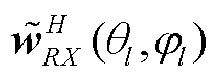
- Taking
FIG. 2 as an example, in case of l=1, thetest antenna 1 transmits a reception calibration signal, and the direction angle of the reception calibration signal is (θq = 0°,ϕq = 5°). The active antenna array performs, according to the beam weight vector corresponding to the direction angle (θq = 0°, ϕq = 5°) in the reception channel beam weight matrix, received beamforming on the reception calibration signal transmitted by thetest antenna 1, and performs calculation to obtain the reception channel beam gain corresponding to the beam direction region l. - S304: The active antenna array determines a difference value between the reception channel beam gain corresponding to the first beam direction region and the reception channel beam gain corresponding to the reference beam direction, and proceeds to S306 if the difference value is greater than a set gain error threshold, otherwise, proceeds to S305.
- The gain error threshold may be preset. The value of the gain error threshold may be determined according to a requirement for the calibration accuracy. If the calibration accuracy is higher, the gain error threshold is smaller.
- S305: The active antenna array determines that the calibration for the beam weight vector corresponding to the first beam direction region in the reception channel beam weight matrix is completed.
- If the difference value between the reception channel beam gain corresponding to the first beam region and the reception channel beam gain corresponding to the reference beam direction is less than the set gain error threshold at S304, it is indicated that a reception channel error of the active antenna array is relatively small in all received beam directions corresponding to the first beam direction region, so that the reception beam weight vector corresponding to the first beam direction region in the reception channel beam weight matrix may be kept unchanged, that is, there is no need to perform error calibration for the reception channels in the received beam directions corresponding to the first beam direction region.
- S306: The active antenna array performs at most K reception channel calibration iteration processes, so as to update the beam weight vector, corresponding to the direction angle of the reception calibration signal that is from the first beam direction region, in the reception channel beam weight matrix, thereby realizing calibration for the reception channels of the active antenna array in the received beam directions corresponding to the first beam direction region.
- The reception channel calibration iteration process may refer to
FIG. 4 . - For each beam direction region, the reception channels of the active antenna array may be all calibrated according to S303 to S306 in the foregoing flow, thereby realizing the calibration for the reception channels of the active antenna array in all the received beam directions.
- Referring to
FIG. 4 , it is a flow diagram of a reception channel calibration iteration process not in accordance with the invention. As shown in the figure, the flow may include the following. - S401: The active antenna array obtains, according to the reception calibration signal from the first beam direction region, an amplitude and phase error vector of N reception channels of the active antenna array in the first beam direction region.
- The lth beam direction region is taken as an example. The amplitude and phase error vector of the N reception channels of the active antenna array in the lth beam direction region is:


- S402: The active antenna array updates, according to the amplitude and phase error determined in the current iteration process, a received beam weight vector in a received beam direction in the first beam direction region in the reception channel beam weight matrix.
- The lth beam direction region is taken as an example. The direction angle of the reception calibration signal of the test antenna from the lth beam direction region is (θl , ϕl ) . The lth beam direction region corresponds to all received beam directions in the following direction angle range: the azimuth angle range is
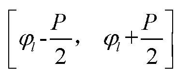
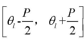
- If the received beam direction corresponding to the azimuth angle range


- S403: The active antenna array uses, according to the direction angle of the reception calibration signal from the first beam direction region, the updated beam weight vector of the corresponding direction angle in the reception channel beam weight matrix to perform beamforming on the reception calibration signal from the first beam direction region to obtain a reception channel beam gain corresponding to the first beam direction region.
- S404: The active antenna array determines whether a gain error between the reception channel beam gain determined in the current iteration process and the reception channel beam gain corresponding to the reference beam direction is greater than a gain error threshold, and proceeds to S406 if the gain error is greater than the gain error threshold, otherwise, S405 is executed.
- S405: The current iteration process is ended, and the calibration for the beam weight vector corresponding to the first beam direction region is completed.
- S406: It is determined whether the maximum number of iterations has been reached; S407 is executed if the maximum number of iterations has been reached, otherwise, S408 is executed.
- S407: The current iteration process is ended to further end the reception channel calibration flow, and warning information indicating that the reception channel calibration is abnormal may be sent.
- S408: The active antenna array receives a reception calibration signal from the first beam direction region, and S401 is executed to perform the next iteration process.
- A scenario shown in
FIG. 2 is taken as an example. In the process of calibrating the reception channels of the active antenna array, a reception calibration signal is transmitted through thetest antenna 0 at first, and the direction angle of the signal is (θq = 0°,ϕq = 0°). The active antenna array updates, according to S301 to S302 inFIG. 3 , each beam weight vector in the reception channel beam weight matrix, and then uses the reception calibration signal with the direction angle of (θq = 0°,ϕq = 0°) to perform initial calibration on the reception channels. - Later, the reception calibration signal is transmitted through the
test antenna 1, and the direction angle of this signal is (θq = 0°,ϕq = 5°). The active antenna array determines, according to S303 to S304 inFIG. 3 , whether to update the several beam weight vectors within the direction angle range of (θ,ϕ)∈[θl -2.5°,θl +2.5°]∩[ϕl -2.5°,ϕl +2.5°] corresponding to this direction angle; and executes, according to the flow shown inFIG. 4 , a reception channel calibration iteration process if updating is needed until the several beam weight vectors in the direction angle range of (θ,ϕ)∈ [θl -2.5°,θ l+2.5°]∩[ϕl-2.5°,ϕl +2.5°] are completely updated, or until the updating fails. If updating is not needed, the several beam weight vectors in the direction angle range of (θ,ϕ)∈[θl -2.5°,θl +2.5°]∩[ϕl -2.5°,ϕl +2.5°] are kept unchanged. - Hereafter, for other beam direction regions, reception calibration signals are transmitted in sequence through the corresponding test antennas; and the reception calibration signal transmitted by each test antenna is processed according to the processing flow of reception channel calibration for the calibration signal transmitted by the
test antenna 1 until the reception channel calibration is completed for all the beam direction regions. - It can been seen through the embodiments of the above reception channel calibration that: at first, the reception calibration signal in the reference beam direction is used to initially update the reception channel beam weight matrix, that is, to initially calibrate the reception channels; then, the beam weight vectors in a plurality of beam directions in a corresponding beam direction region range are updated respectively for different beam direction regions, so as to regionally update the beam weight vectors corresponding to the corresponding regions in the reception channel beam weight matrix, that is, to regionally calibrate the reception channels.
- By adopting the method for calibrating the reception channel according to the above embodiments of the present disclosure, the beamforming functions of related devices of a large-scale active antenna array can be calibrated and detected under a production environment. Compared with the prior art, the method for calibrating the reception channel mainly has the following several advantages.
- (1) The method for calibrating the reception channel according to the embodiments of the present disclosure does not need to be carried out in an anechoic chamber, so that the requirement standard and a heavy investment for a test site are lowered.
- (2) The method for calibrating the reception channel according to the embodiments of the present disclosure performs limited detection in vertical and horizontal spatial dimensions only, so that the production detection efficiency is improved.
- (3) The method for calibrating the reception channel according to the embodiments of the present disclosure is independent of a transmission channel calibration process, and can compensate an amplitude-phase error between a transmission channel and a reception channel and improve the beamforming functionality.
- (4) The method for calibrating the reception channel according to the embodiments of the present disclosure is convenient for algorithm realization, and is favorable for being used in an actual production environment.
- The embodiments of the present disclosure also provide a method for calibrating transmission channels for an active antenna array.
- A transmission channel calibration process and the reception channel calibration process of the active antenna array may use the same calibration environment. A building method for the calibration environment may refer to the foregoing embodiment, and no more repeated descriptions will be provided here.
- A transmission channel beam weight matrix W of the active antenna array includes beam weight vectors corresponding to a plurality of transmitted beam directions (i.e., a plurality of direction angles). Where the beam weight vector of one transmitted beam direction includes beam weights of N transmission channels corresponding to the one transmitted beam direction. N is the number of the transmission channels of the active antenna array, and N is an integer greater than 1.
- Supposing that the transmission channel beam weight matrix W includes beam weight vectors corresponding to Q (Q is an integer greater than 1) transmitted beam directions (i.e., Q direction angles), a space range corresponding to the Q transmitted beam directions may be divided into L (L is an integer greater than 1, L<Q) beam direction regions according to the placement positions and the number of the test antennas. Each beam direction region corresponds to at least one beam direction, and at least one beam direction region in the L beam direction regions corresponds to a plurality of beam directions. The active antenna array may store a correspondence between each beam direction region and the transmitted beam directions.
- Before calibration, the transmission channel beam weight matrix of the active antenna array is represented as W TX = W . That is, before the calibration, the transmission channel beam weight matrix of the active antenna array is set to be the same as the initial beam weight matrix W.
- Referring to
FIG. 5 , it is a schematic diagram of a transmission channel calibration flow for an active antenna array according to the embodiment of the present disclosure. - Before the transmission channels are calibrated, a sequence of a transmission calibration signal may be generated at first. The transmission calibration signal is transmitted by the active antenna array to a test antenna to calibrate the transmission channels of the active antenna array.
- During specific implementation, a frequency domain sequence Sn (k) , k = 1,2,···K' , n = 1,2,···N of the transmission calibration signal and a time domain sequence sn (m), m = 1,2,···M , n =1,2,···N of the transmission calibration signal may be generated for each transmission channel according to a working bandwidth BW of the system, and N is the number of the transmission channels.
- A transformation relation between the time domain sequence and the frequency domain sequence of the transmission calibration signal is:


- Where F[·] represents fast fourier transform, and F -1[·] represents inverse fast fourier transform.
- In order to realize simplicity and convenience of operation of the fast fourier transform for the time domain and the frequency domain in the process for realizing calibration, the length of the time domain sequence of the transmission calibration signal may be set to be M = 2 floor[log
2 K]+1 . - As shown in the
FIG. 5 , the flow may include the following. - S501: The active antenna array uses a beam weight vector in a reference beam direction in the transmission channel beam weight matrix to transmit a transmission calibration signal.
- The reference beam direction may correspond to a direction angle (θq = 0°,ϕq = 0°), and the direction angle (θq = 0°,ϕq = 0°) represents an azimuth angle ϕq = 0° and a pitching angle θq = 0°. The embodiments of the present disclosure are described by taking the reference beam direction corresponding to an azimuth angle ϕq = 0° and a pitching angle θq = 0° as an example.
- In this step, the reference beam direction having the direction angle (θq = 0°,ϕq = 0°) is taken as an example. Each transmission channel of the active antenna array uses a beam weight in the direction angle (θq = 0°,ϕq = 0°) to transmit a time domain sequence sn (m), m = 1,2,···M, n = 1,2,···N of a transmission calibration sequence corresponding to the corresponding transmission channel at a rated nominal power P TX 0. The test antenna corresponding to the direction angle (θq = 0°,ϕq = 0°) receives the transmission calibration signal, and the received signal is expressed as xTX (m), m = 1,2,···M .
- S502: The active antenna array obtains a reception sequence of the transmission calibration signal, obtains, according to the reception sequence, an initial amplitude and phase error vector of each transmission channel in the active antenna array, and updates, according to the initial amplitude and phase error vector of each transmission channel, the transmission calibration signal and the transmission channel beam weight matrix.
- After synchronization and time-frequency domain transformation processing is performed on a signal received by the test antenna, a frequency domain calibration sequence Xn(k), k = 1,2,···K',n = 1,2,···N corresponding to each transmission channel of the active antenna array is obtained, and the frequency domain calibration sequence used as a reception sequence is transmitted to the active antenna array. The process of performing the synchronization and time-frequency domain transformation processing and transmitting the processed frequency domain calibration sequence to the active antenna array may be executed by the test antenna, or executed by other devices. The embodiments of the present disclosure do not limit this.
- The active antenna array determines, according to the reception sequence of the nth transmission channel, that an amplitude and phase error needing to be compensated of the nth transmission channel at a center frequency point f0 is:


- Since the length of the transmission calibration frequency domain sequence of each transmission channel is K, N-times linear interpolation fitting needs to be performed on hn (k), to obtain an amplitude and phase error calibration vector, needing to be compensated within a frequency domain bandwidth, of each transmission channel:

- The active antenna array may use the following formula to update, according to the amplitude and phase error of each transmission channel, the transmission calibration signal: a point multiplication operation is performed on the frequency domain sequence of the transmission calibration signal transmitted by each transmission channel and each element in the amplitude and phase error calibration vector H n , needing to be compensated within a frequency domain bandwidth, of each transmission channel:

- An updated time domain sequence of each transmission channel is obtained through inverse fourier transform. The time domain sequence of the nth transmission channel is expressed as:

- The active antenna array compensates for the channel amplitude and phase error at the center frequency point f0 on the transmission channel beam weight matrix W TX , that is, it is set that:


- Where W TX is an updated transmission channel beam weight matrix after the amplitude and phase error is calibrated in the reference beam direction (such as a beam direction at θq = 0°, ϕq = 0°), and hTX is an error vector, needing to be compensated at the center frequency point f0, of the N transmission channels.
- S503: The active antenna array transmits the updated transmission calibration signal by using the beam weight vector in the reference beam direction in the updated transmission channel beam weight matrix, and performs, according to the beam weight vector in the reference beam direction in the transmission channel beam weight matrix, beamforming on the reception sequence of the updated transmission calibration signal to obtain a transmission channel beam gain corresponding to the reference beam direction.
- The direction angle (θq = 0°,ϕq = 0°) corresponding to the reference beam direction is taken as an example. The active antenna array transmits the updated transmission calibration signal at the rated nominal power P TX 0 by using the beam weight vector w̃TX (0°,0°), and the time domain sequence of the transmission calibration signal of each transmission channel is

- The time domain sequence of the signal received by the test antenna corresponding to the direction angle (θq = 0°, ϕq = 0°) is


- Where G TX 0 represents the transmission channel beam gain corresponding to the reference beam direction (the azimuth angle is ϕq = 0° and the pitching angle is θq = 0°), and

- S504: The active antenna array transmits a transmission calibration signal by using the beam weight vector corresponding to a direction angle of a first beam direction region, and performs beamforming on the reception sequence of the transmission calibration signal by using the beam weight vector corresponding to the direction angle in the transmission channel beam weight matrix, to obtain a transmission channel beamforming gain corresponding to the first beam direction region.
- The "first beam direction region" may be any beam region in L beam regions obtained by division. The direction angle corresponding to the first beam direction region is different from a direction angle corresponding to the reference beam direction.
- In this step, the lth beam region is taken as an example. The active antenna array transmits the updated transmission calibration signal by using the beam weight vector w̃TX (θl ,ϕl ) corresponding to the direction angle (θl ,ϕl ). The test antenna corresponding to the direction angle (θl ,ϕl ) receives the transmission calibration signal, and the time domain sequence of the transmission calibration signal received by the test antenna is

- The active antenna array performs beamforming on


- Where GTXl represents the transmission channel beam gain corresponding to the lth beam region; and

- Taking
FIG. 2 as an example, in case of l=1, the active antenna array transmits the transmission calibration signal, and the direction angle of the transmission calibration signal is (θq = 0°,ϕq = 5°). Thetest antenna 1 receives the transmission calibration signal, and the time domain sequence of the transmission calibration signal received by thetest antenna 1 is transmitted to the active antenna array. The active antenna array performs, according to the beam weight vector in the direction angle (θq = 0°,ϕq = 5°) in the reception channel beam weight matrix, received beamforming on the reception sequence of the transmission calibration signal, and performs calculation to obtain the reception channel beam gain corresponding to the beam direction region l. - S505: The active antenna array determines a difference value between the transmission channel beam gain corresponding to the first beam direction region and the transmission channel beam gain corresponding to the reference beam direction, and proceeds to S506 if the difference value is less than or equal to a set gain error threshold, otherwise, proceeds to S507.
- The gain error threshold may be preset. The value of the gain error threshold may be determined according to a requirement for the calibration accuracy. If the calibration accuracy is higher, the gain error threshold is smaller.
- S506: The active antenna array determines that the calibration for the beam weight vector corresponding to the first beam direction region in the transmission channel beam weight matrix is completed.
- If the difference value between the transmission channel beam gain corresponding to the first beam region and the transmission channel beam gain corresponding to the reference beam direction is less than the set gain error threshold at S505, it is indicated that a transmission channel error of the active antenna array in all transmitted beam directions corresponding to the first beam direction region is relatively small, so that all the beam weight vectors corresponding to the first beam direction region in the transmission channel beam weight matrix may be kept unchanged, that is, there is no need to perform error calibration for the reception channels in the beam directions corresponding to the first beam direction region.
- S507: The active antenna array performs at most K transmission channel calibration iteration processes, so as to update the beam weight vectors in all beam directions in the first beam direction region in the transmission channel beam weight matrix, thereby realizing calibration for the transmission channels of the active antenna array in the beam directions corresponding to the first beam direction region.
- The transmission channel calibration iteration process may refer to
FIG. 6 . - For each beam direction region, the transmission channels of the active antenna array may be all calibrated according to S504 to S507 in the foregoing flow, thereby realizing the calibration for the transmission channels of the active antenna array in all the transmitted beam directions.
- Referring to
FIG. 6 , it is a flow diagram of a transmission channel calibration iteration process according to the embodiment of the present disclosure. As shown in the figure, the flow may include the following. - S601: The active antenna array obtains, according to the reception sequence of the transmission calibration signal transmitted by using the beam weight vector corresponding to the direction angle in the first beam direction region, an amplitude and phase error vector of the N transmission channels of the active antenna array in the first beam direction region.
- The lth beam direction region is taken as an example. The active antenna array determines, according to the reception sequence of the nth transmission channel, that an amplitude and phase error needing to be compensated of the nth transmission channel at a center frequency point f0 corresponding to the direction angle (θl ,ϕl ) is:


- S602: The active antenna array updates, according to the amplitude and phase error vector determined in the current iteration process, the transmission calibration signal and the beam weight vector in the beam direction in the first beam direction region in the transmission channel beam weight matrix.
- In this step, the active antenna array may update, according to the formula (22), the transmission calibration signal. The time domain sequence of the updated transmission calibration signal of each transmission channel is

- The lth beam direction region is taken as an example, and the direction angle corresponding the lth beam direction region is (θ l , ϕl ) . The beam direction region corresponds to all the beam directions in the following direction angle range: the azimuth angle range is


- If the beam direction corresponding to the azimuth angle range


- S603: The active antenna array transmits the updated transmission calibration signal by using the beam weight vector corresponding to the direction angle of the first beam direction region, and performs beamforming on the reception sequence of the transmission calibration signal by using the updated beam weight vector corresponding to the direction angle in the transmission channel beam weight matrix, to obtain a transmission channel beamforming gain corresponding to the first beam direction region.
- S604: The active antenna array determines whether a gain error between the transmission channel beam gain determined in the current iteration process and a transmission beamforming gain corresponding to the reference beam direction is greater than a gain error threshold, and proceeds to S605 if the gain error is less than or equal to the gain error threshold, otherwise, proceeds to S606.
- S605: The calibration for the beam weight vector corresponding to the first beam direction region is completed.
- S606: It is determined whether the maximum number of iterations has been reached; and S607 is executed if the maximum number of iterations has been reached.
- S607: The current iteration process is ended to further end the transmission channel calibration flow, and warning information indicating that the transmission channel calibration is abnormal may be sent.
- S608: The active antenna array transmits a transmission calibration signal by using the beam weight vector of the direction angle corresponding to the first beam direction region, and obtains a reception sequence of the transmission calibration signal, and proceeds to S601 to enter the next iteration process.
- A scenario shown in
FIG. 2 is taken as an example. In the process of calibrating the transmission channels of the active antenna array, the active antenna array firstly transmits a transmission calibration signal by using the beam weight vector corresponding to the direction angle (θq = 0°,ϕq = 0°), updates, according to S501 to S502 inFIG. 5 , each beam weight vector in the transmission channel beam weight matrix, and then initially calibrates the transmission channels by using the reception sequence of the transmission calibration signal with the direction angle (θq = 0°,ϕq = 0°). - Later, the transmission calibration signal is transmitted through the
test antenna 1, and the direction angle of this signal is (θq = 0°,ϕq = 5°). The active antenna array determines, according to S503 to S504 inFIG. 5 , whether to update the several beam weight vectors within the direction angle range of (θ,ϕ)∈[θl -2.5°,θl +2.5°]∩[ϕl-2.5°,ϕl +2.5°] corresponding to this direction angle, and executes, according to the flow shown inFIG. 6 , a transmission channel calibration iteration process if updating is needed until the several beam weight vectors in the direction angle range of (θ,ϕ)∈[θl -2.5°,θl +2.5°]∩[ϕl-2.5°,ϕl +2.5°] are completely updated, or until the updating fails. If updating is not needed, the several beam weight vectors in the direction angle range of (θ,ϕ)∈[θl -2.5°,θl +2.5°]∩[ϕl -2.5°,ϕl +2.5°] are kept unchanged. - Hereafter, for other beam direction regions, the beam weight vectors corresponding to the direction angles of the corresponding beam direction regions are used to transmit transmission calibration signals in sequence; and according to the reception sequence of the transmission calibration signal, the transmission calibration signal is processed according to the transmission channel calibration flow for the
beam direction region 1 in the above flow until the transmission channel calibration is completed for all the beam direction regions. - It can been seen through the embodiments of the above transmission channel calibration that: at first, the reception sequence of the transmission calibration signal in the reference beam direction is used to initially update the transmission channel beam weight matrix, that is, to initially calibrate the transmission channels; and then, the beam weight vectors in a plurality of beam directions in a corresponding beam direction region range are updated respectively for different beam direction regions, so as to regionally update the beam weight vectors corresponding to the corresponding regions in the transmission channel beam weight matrix, that is, to regionally calibrate the transmission channels.
- By adopting the method for calibrating the transmission channel according to the above embodiments of the present disclosure, the beamforming functions of related devices of a large-scale active antenna array can be calibrated and detected under a production environment. Compared with the prior art, the method for calibrating the transmission channel mainly has the following several advantages.
- (1) The method for calibrating the transmission channel according to the embodiments of the present disclosure does not need to be carried out in an anechoic chamber, so that the requirement standard and a heavy investment for a test site are lowered.
- (2) The method for calibrating the transmission channel according to the embodiments of the present disclosure performs limited detection in vertical and horizontal spatial dimensions only, so that the production detection efficiency is improved.
- (3) The method for calibrating the transmission channel according to the embodiments of the present disclosure is independent of a reception channel calibration process, and can compensate an amplitude-phase error between a transmission channel and a reception channel and improve the beamforming functionality.
- (4) The method for calibrating the transmission channel according to the embodiments of the present disclosure is convenient for algorithm realization, and is favorable for being used in an actual production environment.
- Based on the same technical concept, the embodiments of the present disclosure also provide an apparatus for calibrating an antenna used for calibrating reception channels of an active antenna array.
- Referring to
FIG. 7 , it is a schematic structural diagram of an apparatus for calibrating an antenna used for realizing reception channel calibration not in accordance with the invention. The apparatus is applied to an active antenna array. A received beam direction range corresponding to a reception channel beam weight matrix of the active antenna array is divided into a plurality of beam direction regions; and one beam direction region corresponds to at least one received beam direction, and at least one beam direction region corresponds to a plurality of received beam directions. - Optionally, both an azimuth angle and a pitching angle of the reference beam direction are zero.
- Optionally, the direction angle of the reference beam direction is different from an azimuth angle corresponding to any beam direction region.
- The apparatus may include: an
initial calibration module 701 and aregional calibration module 702 - The
initial calibration module 701 is configured to obtain, according to a reception calibration signal received by the active antenna array from the reference beam direction, an initial amplitude and phase error vector of N reception channels of the active antenna array in the reference beam direction, update, according to the initial amplitude and phase error vector, a beam weight vector in each beam direction in the reception channel beam weight matrix, and perform, according to the updated beam weight vector in the reference beam direction in the reception channel beam weight matrix, beamforming on the reception calibration signal in the reference beam direction to obtain a first reception channel beam gain corresponding to the reference beam direction, where the beam weight vector of one received beam direction includes beam weights of the N reception channels corresponding to the one received beam direction, and N is an integer greater than 1. - The
regional calibration module 702 is configured to perform beamforming on a reception calibration signal in a first beam direction region by using a beam weight vector in a corresponding direction angle in the reception channel beam weight matrix according to the reception calibration signal received by the active antenna array from the first beam direction region and a direction angle corresponding to the first beam direction region, to obtain a second reception channel beam gain corresponding to the first beam direction region; and if a gain error between the second reception channel beam gain and the first reception channel beam gain is greater than a gain error threshold, perform at most K reception channel calibration iteration processes according to the reception calibration signal from the first beam direction region, where K is the maximum number of iterations, and the first beam direction region is one of the plurality of beam direction regions. - In some embodiments, in each iteration process in the at most K reception channel calibration iteration processes, the
regional calibration module 702 executes: - obtaining, according to the reception calibration signal from the first beam direction region, an amplitude and phase error vector of the N reception channels of the active antenna array in the first beam direction region;
- updating the beam weight vector in the beam direction in the first beam direction region in the reception channel beam weight matrix according to the amplitude and phase error vector determined in a current iteration process;
- performing beamforming on the reception calibration signal from the first beam direction region by using the updated beam weight vector in the corresponding direction angle in the reception channel beam weight matrix according to the direction angle of the reception calibration signal from the first beam direction region, to obtain a reception channel beam gain corresponding to the first beam direction region;
- determining whether a gain error between the reception channel beam gain determined in the current iteration process and the first reception channel beam gain is greater than the gain error threshold; if the gain error is greater than the gain error threshold, receiving the reception calibration signal from the first beam direction region in the case of not reaching the maximum number of iterations, and performing a next iteration process; otherwise, ending the current iteration process.
- Based on the same technical concept, the embodiments of the present disclosure also provide an antenna calibration apparatus used for calibrating transmission channels of an active antenna array.
- Referring to
FIG. 8 , it is a schematic structural diagram of an apparatus for calibrating an antenna used for realizing transmission channel calibration according to the embodiment of the present disclosure. The apparatus is applied to an active antenna array. A transmitted beam direction range corresponding to a transmission channel beam weight matrix of the active antenna array is divided into a plurality of beam direction regions; and one beam direction region corresponds to at least one transmitted beam direction, and at least one beam direction region corresponds to a plurality of transmitted beam directions. - Optionally, both an azimuth angle and a pitching angle of the reference beam direction are zero.
- Optionally, the direction angle of the reference beam direction is different from an azimuth angle corresponding to any beam direction region.
- The apparatus may include: an
initial calibration module 801 and aregional calibration module 802. - The
initial calibration module 801 is configured to: obtain an initial amplitude and phase error vector of N transmission channels of the active antenna array according to a reception sequence of a transmission calibration signal transmitted by the active antenna array by using a beam weight vector in a reference beam direction in the transmission channel beam weight matrix, update, according to the initial amplitude and phase error vector, the transmission calibration signal and the beam weight vector in each beam direction in the transmission channel beam weight matrix, transmit the updated transmission calibration signal by using the updated beam weight vector of the reference beam direction in the transmission channel beam weight matrix, and perform, according to the beam weight vector in the reference beam direction, beamforming on the reception sequence of the updated transmission calibration signal to obtain a first transmission channel beam gain corresponding to the reference beam direction, where a beam weight vector of one transmitted beam direction includes beam weights of the N transmission channels corresponding to the one transmitted beam direction, and N is an integer greater than 1. - The
regional calibration module 802 is configured to: after the active antenna array transmits a transmission calibration signal by using a beam weight vector corresponding to a direction angle of a first beam direction region, perform beamforming on a reception sequence of the transmitted transmission calibration signal by using the beam weight vector of the corresponding direction angle in the transmission channel beam weight matrix to obtain a second transmission channel beam gain corresponding to the first beam direction region; and if a gain error between the second transmission channel beam gain and the first transmission channel beam gain is greater than a gain error threshold, perform at most K transmission channel calibration iteration processes, where K is the maximum number of iterations, and the first beam direction region is one of the plurality of beam direction regions. - In some embodiments, in each iteration process in the at most K reception channel calibration iteration processes, the
regional calibration module 802 executes: - obtaining, according to the reception sequence of the transmission calibration signal transmitted by using the beam weight vector corresponding to the direction angle of the first beam direction region, an amplitude and phase error vector of the N transmission channels of the active antenna array in the first beam direction region;
- updating the transmission calibration signal and the beam weight vector of the beam direction in the first beam direction region in the transmission channel beam weight matrix according to the amplitude and phase error vector determined in a current iteration process;
- transmitting the updated transmission calibration signal by using the beam weight vector corresponding to the direction angle in the first beam direction region;
- performing beamforming on the reception sequence of the transmission calibration signal by using the beam weight vector corresponding to the direction angle, to obtain a transmission channel beam gain corresponding to the first beam direction region;
- determining whether a gain error between the transmission channel beam gain determined in the current iteration process and the first transmission channel beam gain is greater than the gain error threshold; if the gain error is greater than the gain error threshold, transmitting the transmission calibration signal by using the beam weight vector of the direction angle corresponding to the first beam direction region in the case of not reaching the maximum number of iterations, and performing a next iteration process; otherwise, ending the current iteration process.
- Based on the same technical concept, the embodiments of the present disclosure also provide a communication apparatus. The communication apparatus can realize the reception channel calibration flow in the foregoing embodiment.
- Referring to
FIG. 9 , it is a schematic structural diagram of a communication apparatus according to the embodiments of the present disclosure. As shown in figure, the communication apparatus may include: aprocessor 901, amemory 902, atransceiver 903 and abus interface 904. - The
processor 901 is responsible for managing the bus architecture and performing usual processing, and thememory 902 may store data used when theprocessor 901 performs operations. Thetransceiver 903 is configured to receive and transmit data under the control of theprocessor 901. - A bus architecture may include any number of interconnected buses and bridges, and is particularly formed by linking one or more of processors represented by the
processor 901 and the various circuits of memories represented by thememory 902 together. The bus architecture may also link various other circuits such as peripherals, voltage regulators and power management circuits, which are well known in the art and, therefore, will not be further described herein. Abus interface 904 provides an interface. Theprocessor 901 is responsible for managing the bus architecture and performing usual processing, and thememory 902 may store data used when theprocessor 901 performs operations. - A flow disclosed by the embodiment of the present disclosure may be applied to the
processor 901, or implemented by theprocessor 901. In the implementation process, each step of a signal processing flow may be completed by integrated logic circuits of hardware in theprocessor 901 or instructions in the form of software. Theprocessor 901 may be a general-purpose processor, a digital signal processor, an application specific integrated circuit, a field programmable gate array or other programmable logic device, a discrete gate or transistor logic device, and a discrete hardware component, and may implement or execute the various methods, steps and logic block diagrams disclosed in the embodiments of the present disclosure. The general-purpose processor may be a microprocessor or any conventional processor. The steps of the method disclosed in conjunction with the embodiment of the present disclosure may be directly embodied as being executed by a hardware processor, or may be executed and completed by a combination of hardware and software modules in the processor. The software module may be located in a mature storage medium in the art, such as a random access memory, a flash memory, a read-only memory, a programmable read-only memory, an electrically erasable programmable memory, and a register. The storage medium is located in thememory 902, and theprocessor 901 reads information in thememory 902 and completes the steps of the signal processing flow in combination with its hardware. - Specifically, the
processor 901 is used for reading programs in thememory 902 to execute the reception channel calibration flow described in the foregoing embodiments. The specific implementation of the flow may refer to the related descriptions of the foregoing embodiments, and no more repeated descriptions will be provided here. - Based on the same technical concept, the embodiments of the present disclosure also provide a communication apparatus. The communication apparatus can realize the transmission channel calibration flow in the foregoing embodiment.
- Referring to
FIG. 10 , it is a schematic structural diagram of a communication apparatus according to the embodiments of the present disclosure. As shown in figure, the communication apparatus may include: aprocessor 1001, amemory 1002, atransceiver 1003 and abus interface 1004. - The
processor 1001 is responsible for managing the bus architecture and performing usual processing, and thememory 1002 may store data used when theprocessor 1001 performs operations. Thetransceiver 1003 is configured to receive and transmit data under the control of theprocessor 1001. - A bus architecture may include any number of interconnected buses and bridges, and is particularly formed by linking one or more of processors represented by the
processor 1001 and the various circuits of memories represented by thememory 1002 together. The bus architecture may also link various other circuits such as peripherals, voltage regulators and power management circuits, which are well known in the art and, therefore, will not be further described herein. Abus interface 1004 provides an interface. Theprocessor 1001 is responsible for managing the bus architecture and performing usual processing, and thememory 1002 may store data used when theprocessor 1001 performs operations. - A flow disclosed by the embodiment of the present disclosure may be applied to the
processor 1001, or implemented by theprocessor 1001. In the implementation process, each step of a signal processing flow may be completed by integrated logic circuits of hardware in theprocessor 1001 or instructions in the form of software. Theprocessor 1001 may be a general-purpose processor, a digital signal processor, an application specific integrated circuit, a field programmable gate array or other programmable logic device, a discrete gate or transistor logic device, and a discrete hardware component, and may implement or execute the various methods, steps and logic block diagrams disclosed in the embodiments of the present disclosure. The general-purpose processor may be a microprocessor or any conventional processor. The steps of the method disclosed in conjunction with the embodiment of the present disclosure may be directly embodied as being executed by a hardware processor, or may be executed and completed by a combination of hardware and software modules in the processor. The software module may be located in a mature storage medium in the art, such as a random access memory, a flash memory, a read-only memory, a programmable read-only memory, an electrically erasable programmable memory, and a register. The storage medium is located in thememory 1002, and theprocessor 1001 reads information in thememory 1002 and completes the steps of the signal processing flow in combination with its hardware. - Specifically, the
processor 1001 is used for reading programs in thememory 1002 to execute the transmission channel calibration flow described in the foregoing embodiments. The specific implementation of the flow may refer to the related descriptions of the foregoing embodiments, and no more repeated descriptions will be provided here. - Based on the same technical concept, the embodiments of the present disclosure further provide a computer-readable storage medium. The computer-readable storage medium stores computer-executable instructions. The computer-executable instructions are configured to cause a computer to execute the flows executed in the foregoing embodiments.
- The present disclosure is described by referring to flowcharts and/or block diagrams of methods, devices (systems) and computer program products according to the embodiments of the present application. It should be understood that computer program instructions may implement each flow and/or each block in the flowcharts and/or the block diagrams and combination of the flows and/or the blocks in the flow diagrams and/or the block diagrams. These computer program instructions may be provided for a general computer, a dedicated computer, an embedded processor or processing units of other programmable data processing devices to generate a machine, thereby making the instructions that are executed by the computer or the processing units of other programmable data processing devices generate apparatuses for realizing specified functions in one or multiple flows of the flow diagrams and/or one or multiple blocks of the block diagrams.
- These computer program instructions may also be stored in a computer readable memory capable of guiding the computer or other programmable data processing devices to work in a specific manner, thereby making the instructions that are stored in the computer readable memory generate manufactured products that include instruction apparatuses. The instruction apparatuses realize the specified functions in one or multiple flows of the flow diagrams and/or one or multiple blocks of the block diagrams.
- These computer program instructions also may be loaded onto the computer or other programmable data processing devices to execute a series of operation steps on the computer or other programmable data processing devices to generate computer implemented processing, so that the instructions executed on the computer or other programmable data processing devices provide steps for realizing the specified functions in one or multiple flows of the flow diagrams and/or one or multiple blocks of the block diagrams.
- Although the preferred embodiments of the present disclosure have been described, those skilled in the art can make other changes and modifications to these embodiments once they acquire the basic creative concept. Therefore, attached claims is intended to be explained as including the preferred embodiments and all the changes and modifications that fall within the scope of the present invention.
- Apparently, those skilled in the art can make various changes and modifications to the present disclosure without departing from the scope of the present invention.
- Therefore, if these changes and modifications of the present disclosure fall within the scope of the claims of the present disclosure, the present disclosure is intended to include these changes and modifications.
Claims (5)
- A method for calibrating an active antenna array, wherein a transmitted beam direction range corresponding to a transmission channel beam weight matrix of an active antenna array is divided into a plurality of beam direction regions; one beam direction region corresponds to at least one transmitted beam direction, and a plurality of beam direction regions correspond to a plurality of transmitted beam directions; and the method comprises:transmitting (S501), by the active antenna array, a transmission calibration signal to a test antenna by using a beam weight vector in a reference beam direction in a transmission channel beam weight matrix; obtaining (S502), according to a reception sequence of the transmission calibration signal, an initial amplitude and phase error vector of N transmission channels of the active antenna array; updating (S502), according to the initial amplitude and phase error vector, the transmission calibration signal and a beam weight vector in each beam direction in the transmission channel beam weight matrix; transmitting (S503) the updated transmission calibration signal to the test antenna by using the updated beam weight vector of the reference beam direction in the transmission channel beam weight matrix; and performing (S503), according to the beam weight vector in the reference beam direction, beamforming on the reception sequence of the updated transmission calibration signal for obtaining a first transmission channel beam gain corresponding to the reference beam direction; wherein a beam weight vector of one transmitted beam direction comprises beam weights of the N transmission channels corresponding to the one transmitted beam direction, and N is an integer greater than 1;transmitting (S504), by the active antenna array, a transmission calibration signal to the test antenna by using a beam weight vector corresponding to a direction angle of a first beam direction region, and performing (S504) beamforming on a reception sequence of the transmitted transmission calibration signal by using the beam weight vector of the corresponding direction angle in the transmission channel beam weight matrix, for obtaining a second transmission channel beam gain corresponding to the first beam direction region; andif a gain error between the second transmission channel beam gain and the first transmission channel beam gain is greater than a gain error threshold, performing (S507) at most K transmission channel calibration iteration processes; wherein K is the maximum number of iterations, and the first beam direction region is one of the plurality of beam direction regions;wherein in each iteration process in the at most K transmission channel calibration iteration processes, the active antenna array executes:obtaining (S601), according to the reception sequence of the transmission calibration signal transmitted by using the beam weight vector corresponding to the direction angle of the first beam direction region, an amplitude and phase error vector of the N transmission channels of the active antenna array in the first beam direction region;updating (S602) the transmission calibration signal and the beam weight vector of the beam direction in the first beam direction region in the transmission channel beam weight matrix according to the amplitude and phase error vector determined in a current iteration process;transmitting (S603) the updated transmission calibration signal to the test antenna by using the beam weight vector corresponding to the direction angle in the first beam direction region;performing (S603) beamforming on the reception sequence of the transmission calibration signal by using the beam weight vector corresponding to the direction angle, for obtaining a transmission channel beam gain corresponding to the first beam direction region; anddetermining (S604) whether a gain error between the transmission channel beam gain determined in the current iteration process and the first transmission channel beam gain is greater than the gain error threshold; if the gain error is greater than the gain error threshold, transmitting (S608) the transmission calibration signal to the test antenna by using the beam weight vector of the direction angle corresponding to the first beam direction region in the case of not reaching the maximum number of iterations, and performing a next iteration process; otherwise, ending (S607) the current iteration process.
- The method according to claim 1, wherein both an azimuth angle and a pitching angle of the reference beam direction are zero.
- The method according to claim 1, wherein the direction angle of the reference beam direction is different from an azimuth angle of any beam direction region.
- An apparatus for calibrating an antenna, applied to an active antenna array, wherein a transmitted beam direction range corresponding to a transmission channel beam weight matrix of the active antenna array is divided into a plurality of beam direction regions; one beam direction region corresponds to at least one transmitted beam direction, and a plurality of beam direction regions correspond to a plurality of transmitted beam directions; and the apparatus comprises:an initial calibration module (801), configured to:obtain an initial amplitude and phase error vector of N transmission channels of the active antenna array according to a reception sequence of a transmission calibration signal transmitted by the active antenna array by using a beam weight vector in a reference beam direction in the transmission channel beam weight matrix,update, according to the initial amplitude and phase error vector, the transmission calibration signal and the beam weight vector in each beam direction in the transmission channel beam weight matrix,transmit the updated transmission calibration signal to a test antenna by using the updated beam weight vector of the reference beam direction in the transmission channel beam weight matrix, andperform, according to the beam weight vector in the reference beam direction, beamforming on the reception sequence of the updated transmission calibration signal for obtaining a first transmission channel beam gain corresponding to the reference beam direction, wherein a beam weight vector of one transmitted beam direction comprises beam weights of the N transmission channels corresponding to the one transmitted beam direction, and N is an integer greater than 1; anda regional calibration module (802), configured to:after the active antenna array transmits a transmission calibration signal to the test antenna by using a beam weight vector corresponding to a direction angle of a first beam direction region, perform beamforming on a reception sequence of the transmitted transmission calibration signal by using the beam weight vector of the corresponding direction angle in the transmission channel beam weight matrix, for obtaining a second transmission channel beam gain corresponding to the first beam direction region; andif a gain error between the second transmission channel beam gain and the first transmission channel beam gain is greater than a gain error threshold, perform at most K transmission channel calibration iteration processes; wherein K is the maximum number of iterations, and the first beam direction region is one of the plurality of beam direction regions;wherein in each iteration process in the at most K transmission channel calibration iteration processes, the regional calibration module (802) executes:obtaining, according to the reception sequence of the transmission calibration signal transmitted by using the beam weight vector corresponding to the direction angle of the first beam direction region, an amplitude and phase error vector of the N transmission channels of the active antenna array in the first beam direction region;updating the transmission calibration signal and the beam weight vector of the beam direction in the first beam direction region in the transmission channel beam weight matrix according to the amplitude and phase error vector determined in a current iteration process;transmitting the updated transmission calibration signal to the test antenna by using the beam weight vector corresponding to the direction angle in the first beam direction region;performing beamforming on the reception sequence of the transmission calibration signal by using the beam weight vector corresponding to the direction angle, for obtaining a transmission channel beam gain corresponding to the first beam direction region; anddetermining whether a gain error between the transmission channel beam gain determined in the current iteration process and the first transmission channel beam gain is greater than the gain error threshold; if the gain error is greater than the gain error threshold, transmitting the transmission calibration signal to the test antenna by using the beam weight vector of the direction angle corresponding to the first beam direction region in the case of not reaching the maximum number of iterations, and performing a next iteration process; otherwise, ending the current iteration process.
- The apparatus according to claim 4, wherein both an azimuth angle and a pitching angle of the reference beam direction are zero; or wherein the direction angle of the reference beam direction is different from an azimuth angle corresponding to any beam direction region.
Applications Claiming Priority (2)
| Application Number | Priority Date | Filing Date | Title |
|---|---|---|---|
| CN201810872421.1A CN110798253B (en) | 2018-08-02 | 2018-08-02 | Antenna calibration method and device |
| PCT/CN2019/097551 WO2020024861A1 (en) | 2018-08-02 | 2019-07-24 | Antenna calibration method and device |
Publications (3)
| Publication Number | Publication Date |
|---|---|
| EP3832912A1 EP3832912A1 (en) | 2021-06-09 |
| EP3832912A4 EP3832912A4 (en) | 2021-08-25 |
| EP3832912B1 true EP3832912B1 (en) | 2024-10-30 |
Family
ID=69231390
Family Applications (1)
| Application Number | Title | Priority Date | Filing Date |
|---|---|---|---|
| EP19844459.8A Active EP3832912B1 (en) | 2018-08-02 | 2019-07-24 | Antenna calibration method and device |
Country Status (6)
| Country | Link |
|---|---|
| US (1) | US11171417B2 (en) |
| EP (1) | EP3832912B1 (en) |
| JP (1) | JP7038899B2 (en) |
| KR (1) | KR102363700B1 (en) |
| CN (1) | CN110798253B (en) |
| WO (1) | WO2020024861A1 (en) |
Families Citing this family (15)
| Publication number | Priority date | Publication date | Assignee | Title |
|---|---|---|---|---|
| CN109309533B (en) * | 2018-09-04 | 2021-05-18 | 华为技术有限公司 | A calibration method and equipment |
| GB2579175B (en) * | 2018-11-01 | 2021-01-06 | Leonardo Mw Ltd | An active array antenna with sub-arrays and a method for its calibration |
| CN111447017B (en) * | 2020-04-09 | 2021-04-30 | 广州通则康威智能科技有限公司 | Array antenna beamforming fast test device and test method |
| CN111463575B (en) * | 2020-04-20 | 2022-02-11 | 上海磐启微电子有限公司 | Amplitude-phase error self-correction device and method based on uniform rectangular planar array |
| US11789118B2 (en) * | 2020-10-23 | 2023-10-17 | Nxp Usa, Inc. | Calibration of a phased array |
| CN112491455B (en) * | 2021-02-05 | 2021-06-01 | 电子科技大学 | Robust beam forming method based on array unit position correction |
| US11984659B2 (en) * | 2021-06-23 | 2024-05-14 | Qualcomm Incorporated | Phase pre-compensation for misalignment |
| US11777618B2 (en) * | 2021-09-14 | 2023-10-03 | Hughes Network Systems, Llc | Amplitude and phase calibration for phased array antennas |
| CN115884210A (en) * | 2021-09-28 | 2023-03-31 | 中国移动通信集团广东有限公司 | Weak coverage cell optimization method and device |
| US12074670B2 (en) * | 2022-02-25 | 2024-08-27 | Qualcomm Incorporated | Methods for beam coordination in a near-field operation with multiple transmission and reception points (TRPS) |
| CN117156451A (en) * | 2022-05-23 | 2023-12-01 | 大唐移动通信设备有限公司 | Beam weight adjustment method, device, access network equipment and storage medium |
| CN115060984B (en) * | 2022-06-13 | 2025-01-14 | 成都华兴大地科技有限公司 | Phased array antenna pointing calibration method suitable for antenna housing with any shape |
| CN115765812B (en) * | 2022-09-29 | 2026-03-31 | 苏州博海创业微系统有限公司 | A method for preprocessing amplitude weights of a large-scale beamforming matrix |
| CN115588851B (en) * | 2022-12-12 | 2023-04-11 | 中国电子科技集团公司第十研究所 | Validity verification method for array element channel phase calibration of spherical phased array antenna |
| CN115833972B (en) * | 2023-02-17 | 2023-04-28 | 华清瑞达(天津)科技有限公司 | System and method for calibrating target angular position output by array feed system |
Family Cites Families (19)
| Publication number | Priority date | Publication date | Assignee | Title |
|---|---|---|---|---|
| SE522563C2 (en) * | 2000-02-01 | 2004-02-17 | Ericsson Telefon Ab L M | Calibration method for an adaptive group antenna |
| US7272364B2 (en) * | 2002-12-30 | 2007-09-18 | Motorola, Inc. | Method and system for minimizing overlap nulling in switched beams |
| US20090093222A1 (en) | 2007-10-03 | 2009-04-09 | Qualcomm Incorporated | Calibration and beamforming in a wireless communication system |
| US20090288344A1 (en) * | 2008-05-23 | 2009-11-26 | Napoleon Springworks, Inc. | Cable Brake Bracket |
| CN103188009B (en) * | 2011-12-31 | 2018-01-09 | 中兴通讯股份有限公司 | Signal acceptance method and device |
| US10164334B2 (en) * | 2013-04-15 | 2018-12-25 | Nokia Solutions And Networks Oy | Antenna system calibration |
| GB2517218B (en) * | 2013-08-16 | 2017-10-04 | Analog Devices Global | Communication unit and method of antenna array calibration |
| KR20170137074A (en) | 2015-04-10 | 2017-12-12 | 미쓰비시덴키 가부시키가이샤 | Communication system |
| US9967081B2 (en) | 2015-12-04 | 2018-05-08 | Hon Hai Precision Industry Co., Ltd. | System and method for beamforming wth automatic amplitude and phase error calibration |
| CN106324573A (en) * | 2016-08-24 | 2017-01-11 | 中国电子科技集团公司第三十八研究所 | Amplitude-phase error correction method suitable for tablet end-fire array antenna |
| US20180062260A1 (en) * | 2016-08-26 | 2018-03-01 | Analog Devices Global | Antenna array calibration systems and methods |
| CN107809273A (en) * | 2016-09-05 | 2018-03-16 | 中兴通讯股份有限公司 | A kind of multiple antennas compensation method and its device, radio-frequency apparatus |
| CN106371055B (en) * | 2016-10-26 | 2018-11-09 | 黑龙江大学 | Far and near field width band mixed signal super-resolution direction finding array amplitude phase error method of estimation |
| US10680689B2 (en) | 2017-01-05 | 2020-06-09 | Futurewei Technologies, Inc. | Beam management techniques for beam calibration |
| CN109495189B (en) | 2017-09-11 | 2020-08-28 | 大唐移动通信设备有限公司 | Array antenna calibration method and device |
| CN109802818B (en) * | 2017-11-17 | 2022-05-10 | 华为技术有限公司 | Communication method and device |
| CN108155958A (en) * | 2017-11-22 | 2018-06-12 | 西南电子技术研究所(中国电子科技集团公司第十研究所) | Extensive mimo antenna array far field calibration system |
| US11177567B2 (en) * | 2018-02-23 | 2021-11-16 | Analog Devices Global Unlimited Company | Antenna array calibration systems and methods |
| JP7731672B2 (en) * | 2018-06-22 | 2025-09-01 | フラウンホーファー-ゲゼルシャフト・ツール・フェルデルング・デル・アンゲヴァンテン・フォルシュング・アインゲトラーゲネル・フェライン | Method, measurement environment and device under test |
-
2018
- 2018-08-02 CN CN201810872421.1A patent/CN110798253B/en active Active
-
2019
- 2019-07-24 KR KR1020217006394A patent/KR102363700B1/en active Active
- 2019-07-24 US US17/265,360 patent/US11171417B2/en active Active
- 2019-07-24 JP JP2021505832A patent/JP7038899B2/en active Active
- 2019-07-24 WO PCT/CN2019/097551 patent/WO2020024861A1/en not_active Ceased
- 2019-07-24 EP EP19844459.8A patent/EP3832912B1/en active Active
Also Published As
| Publication number | Publication date |
|---|---|
| US20210257730A1 (en) | 2021-08-19 |
| US11171417B2 (en) | 2021-11-09 |
| JP2021524721A (en) | 2021-09-13 |
| KR20210040113A (en) | 2021-04-12 |
| EP3832912A1 (en) | 2021-06-09 |
| WO2020024861A1 (en) | 2020-02-06 |
| CN110798253B (en) | 2021-03-12 |
| CN110798253A (en) | 2020-02-14 |
| JP7038899B2 (en) | 2022-03-18 |
| EP3832912A4 (en) | 2021-08-25 |
| KR102363700B1 (en) | 2022-02-15 |
Similar Documents
| Publication | Publication Date | Title |
|---|---|---|
| US11171417B2 (en) | Method and apparatus for calibrating antenna | |
| EP3683984B1 (en) | Array antenna calibration method and device | |
| US10684318B1 (en) | System and method for testing analog beamforming device | |
| EP3349367B1 (en) | Method of determining communication beam, and corresponding device | |
| US11962357B2 (en) | Method and system for testing wireless performance of wireless terminal | |
| EP3565134B1 (en) | Antenna correction method and device | |
| EP2533360A1 (en) | Method and device for antenna calibration | |
| EP3905553A1 (en) | Radio frequency performance testing method and apparatus of wireless device, and tester | |
| EP3280168A1 (en) | Method, device and communication system for obtaining beam information | |
| Choi et al. | Channel extrapolation for FDD massive MIMO: Procedure and experimental results | |
| Wang et al. | On efficient non-stationary channel emulation in conductive phase matrix setup for massive MIMO performance testing | |
| US12034504B2 (en) | PIM downlink subspace acquisition method | |
| EP3796568B1 (en) | Antenna connection detection method, network side device and computer-readable storage medium | |
| US20220182156A1 (en) | Antenna calibration apparatus and antenna calibration method | |
| US20250240103A1 (en) | Calibration of a phase shift matrix for cable-connected testing of a massive multiple-input multiple-output base station | |
| CN102271349B (en) | System and method for function test of uplink IRC (Interference Restraint Combination) algorithm | |
| Wang et al. | Faulty RIS-aided integrated sensing and communication: Modeling and optimization | |
| Martinez-Ingles et al. | Initial experimental characterization of the millimeter-wave radio channel | |
| WO2024234373A1 (en) | A test method for ecc calculation based on ota 2 tx trp measurement | |
| CN104218983B (en) | Joint channel bearing calibration and device | |
| CN119483778A (en) | Virtual Cable Calibration for Over-the-Air Conformance Testing | |
| US20260066965A1 (en) | Creating channels for network testing using network beam information | |
| WO2009089990A1 (en) | Method for determining the position of an object using a mimo wlan radio network | |
| CN121985350A (en) | Methods, apparatus, systems and storage media for probe layout optimization in air interface testing | |
| CN117639965A (en) | Multi-channel correction method, device, electronic equipment and storage medium |
Legal Events
| Date | Code | Title | Description |
|---|---|---|---|
| STAA | Information on the status of an ep patent application or granted ep patent |
Free format text: STATUS: THE INTERNATIONAL PUBLICATION HAS BEEN MADE |
|
| PUAI | Public reference made under article 153(3) epc to a published international application that has entered the european phase |
Free format text: ORIGINAL CODE: 0009012 |
|
| STAA | Information on the status of an ep patent application or granted ep patent |
Free format text: STATUS: REQUEST FOR EXAMINATION WAS MADE |
|
| 17P | Request for examination filed |
Effective date: 20210210 |
|
| AK | Designated contracting states |
Kind code of ref document: A1 Designated state(s): AL AT BE BG CH CY CZ DE DK EE ES FI FR GB GR HR HU IE IS IT LI LT LU LV MC MK MT NL NO PL PT RO RS SE SI SK SM TR |
|
| A4 | Supplementary search report drawn up and despatched |
Effective date: 20210726 |
|
| RIC1 | Information provided on ipc code assigned before grant |
Ipc: H04B 17/12 20150101AFI20210720BHEP Ipc: H01Q 3/00 20060101ALI20210720BHEP |
|
| DAV | Request for validation of the european patent (deleted) | ||
| DAX | Request for extension of the european patent (deleted) | ||
| STAA | Information on the status of an ep patent application or granted ep patent |
Free format text: STATUS: EXAMINATION IS IN PROGRESS |
|
| 17Q | First examination report despatched |
Effective date: 20230509 |
|
| RAP1 | Party data changed (applicant data changed or rights of an application transferred) |
Owner name: DATANG MOBILE COMMUNICATIONS EQUIPMENT CO., LTD. Owner name: CICT MOBILE COMMUNICATION TECHNOLOGY CO., LTD |
|
| GRAP | Despatch of communication of intention to grant a patent |
Free format text: ORIGINAL CODE: EPIDOSNIGR1 |
|
| GRAP | Despatch of communication of intention to grant a patent |
Free format text: ORIGINAL CODE: EPIDOSNIGR1 |
|
| STAA | Information on the status of an ep patent application or granted ep patent |
Free format text: STATUS: GRANT OF PATENT IS INTENDED |
|
| INTG | Intention to grant announced |
Effective date: 20240614 |
|
| GRAS | Grant fee paid |
Free format text: ORIGINAL CODE: EPIDOSNIGR3 |
|
| GRAA | (expected) grant |
Free format text: ORIGINAL CODE: 0009210 |
|
| STAA | Information on the status of an ep patent application or granted ep patent |
Free format text: STATUS: THE PATENT HAS BEEN GRANTED |
|
| AK | Designated contracting states |
Kind code of ref document: B1 Designated state(s): AL AT BE BG CH CY CZ DE DK EE ES FI FR GB GR HR HU IE IS IT LI LT LU LV MC MK MT NL NO PL PT RO RS SE SI SK SM TR |
|
| REG | Reference to a national code |
Ref country code: GB Ref legal event code: FG4D |
|
| REG | Reference to a national code |
Ref country code: CH Ref legal event code: EP |
|
| REG | Reference to a national code |
Ref country code: DE Ref legal event code: R096 Ref document number: 602019061250 Country of ref document: DE |
|
| REG | Reference to a national code |
Ref country code: IE Ref legal event code: FG4D |
|
| REG | Reference to a national code |
Ref country code: LT Ref legal event code: MG9D |
|
| REG | Reference to a national code |
Ref country code: NL Ref legal event code: MP Effective date: 20241030 |
|
| PG25 | Lapsed in a contracting state [announced via postgrant information from national office to epo] |
Ref country code: HR Free format text: LAPSE BECAUSE OF FAILURE TO SUBMIT A TRANSLATION OF THE DESCRIPTION OR TO PAY THE FEE WITHIN THE PRESCRIBED TIME-LIMIT Effective date: 20241030 Ref country code: PT Free format text: LAPSE BECAUSE OF FAILURE TO SUBMIT A TRANSLATION OF THE DESCRIPTION OR TO PAY THE FEE WITHIN THE PRESCRIBED TIME-LIMIT Effective date: 20250228 Ref country code: IS Free format text: LAPSE BECAUSE OF FAILURE TO SUBMIT A TRANSLATION OF THE DESCRIPTION OR TO PAY THE FEE WITHIN THE PRESCRIBED TIME-LIMIT Effective date: 20250228 |
|
| PG25 | Lapsed in a contracting state [announced via postgrant information from national office to epo] |
Ref country code: NL Free format text: LAPSE BECAUSE OF FAILURE TO SUBMIT A TRANSLATION OF THE DESCRIPTION OR TO PAY THE FEE WITHIN THE PRESCRIBED TIME-LIMIT Effective date: 20241030 Ref country code: FI Free format text: LAPSE BECAUSE OF FAILURE TO SUBMIT A TRANSLATION OF THE DESCRIPTION OR TO PAY THE FEE WITHIN THE PRESCRIBED TIME-LIMIT Effective date: 20241030 |
|
| REG | Reference to a national code |
Ref country code: AT Ref legal event code: MK05 Ref document number: 1737946 Country of ref document: AT Kind code of ref document: T Effective date: 20241030 |
|
| PG25 | Lapsed in a contracting state [announced via postgrant information from national office to epo] |
Ref country code: BG Free format text: LAPSE BECAUSE OF FAILURE TO SUBMIT A TRANSLATION OF THE DESCRIPTION OR TO PAY THE FEE WITHIN THE PRESCRIBED TIME-LIMIT Effective date: 20241030 |
|
| PG25 | Lapsed in a contracting state [announced via postgrant information from national office to epo] |
Ref country code: ES Free format text: LAPSE BECAUSE OF FAILURE TO SUBMIT A TRANSLATION OF THE DESCRIPTION OR TO PAY THE FEE WITHIN THE PRESCRIBED TIME-LIMIT Effective date: 20241030 |
|
| PG25 | Lapsed in a contracting state [announced via postgrant information from national office to epo] |
Ref country code: NO Free format text: LAPSE BECAUSE OF FAILURE TO SUBMIT A TRANSLATION OF THE DESCRIPTION OR TO PAY THE FEE WITHIN THE PRESCRIBED TIME-LIMIT Effective date: 20250130 |
|
| PG25 | Lapsed in a contracting state [announced via postgrant information from national office to epo] |
Ref country code: AT Free format text: LAPSE BECAUSE OF FAILURE TO SUBMIT A TRANSLATION OF THE DESCRIPTION OR TO PAY THE FEE WITHIN THE PRESCRIBED TIME-LIMIT Effective date: 20241030 Ref country code: LV Free format text: LAPSE BECAUSE OF FAILURE TO SUBMIT A TRANSLATION OF THE DESCRIPTION OR TO PAY THE FEE WITHIN THE PRESCRIBED TIME-LIMIT Effective date: 20241030 Ref country code: GR Free format text: LAPSE BECAUSE OF FAILURE TO SUBMIT A TRANSLATION OF THE DESCRIPTION OR TO PAY THE FEE WITHIN THE PRESCRIBED TIME-LIMIT Effective date: 20250131 |
|
| PG25 | Lapsed in a contracting state [announced via postgrant information from national office to epo] |
Ref country code: PL Free format text: LAPSE BECAUSE OF FAILURE TO SUBMIT A TRANSLATION OF THE DESCRIPTION OR TO PAY THE FEE WITHIN THE PRESCRIBED TIME-LIMIT Effective date: 20241030 |
|
| PG25 | Lapsed in a contracting state [announced via postgrant information from national office to epo] |
Ref country code: RS Free format text: LAPSE BECAUSE OF FAILURE TO SUBMIT A TRANSLATION OF THE DESCRIPTION OR TO PAY THE FEE WITHIN THE PRESCRIBED TIME-LIMIT Effective date: 20250130 |
|
| PG25 | Lapsed in a contracting state [announced via postgrant information from national office to epo] |
Ref country code: SM Free format text: LAPSE BECAUSE OF FAILURE TO SUBMIT A TRANSLATION OF THE DESCRIPTION OR TO PAY THE FEE WITHIN THE PRESCRIBED TIME-LIMIT Effective date: 20241030 |
|
| PG25 | Lapsed in a contracting state [announced via postgrant information from national office to epo] |
Ref country code: DK Free format text: LAPSE BECAUSE OF FAILURE TO SUBMIT A TRANSLATION OF THE DESCRIPTION OR TO PAY THE FEE WITHIN THE PRESCRIBED TIME-LIMIT Effective date: 20241030 |
|
| PG25 | Lapsed in a contracting state [announced via postgrant information from national office to epo] |
Ref country code: EE Free format text: LAPSE BECAUSE OF FAILURE TO SUBMIT A TRANSLATION OF THE DESCRIPTION OR TO PAY THE FEE WITHIN THE PRESCRIBED TIME-LIMIT Effective date: 20241030 |
|
| PG25 | Lapsed in a contracting state [announced via postgrant information from national office to epo] |
Ref country code: RO Free format text: LAPSE BECAUSE OF FAILURE TO SUBMIT A TRANSLATION OF THE DESCRIPTION OR TO PAY THE FEE WITHIN THE PRESCRIBED TIME-LIMIT Effective date: 20241030 |
|
| PG25 | Lapsed in a contracting state [announced via postgrant information from national office to epo] |
Ref country code: SK Free format text: LAPSE BECAUSE OF FAILURE TO SUBMIT A TRANSLATION OF THE DESCRIPTION OR TO PAY THE FEE WITHIN THE PRESCRIBED TIME-LIMIT Effective date: 20241030 |
|
| PG25 | Lapsed in a contracting state [announced via postgrant information from national office to epo] |
Ref country code: CZ Free format text: LAPSE BECAUSE OF FAILURE TO SUBMIT A TRANSLATION OF THE DESCRIPTION OR TO PAY THE FEE WITHIN THE PRESCRIBED TIME-LIMIT Effective date: 20241030 |
|
| PG25 | Lapsed in a contracting state [announced via postgrant information from national office to epo] |
Ref country code: IT Free format text: LAPSE BECAUSE OF FAILURE TO SUBMIT A TRANSLATION OF THE DESCRIPTION OR TO PAY THE FEE WITHIN THE PRESCRIBED TIME-LIMIT Effective date: 20241030 |
|
| REG | Reference to a national code |
Ref country code: DE Ref legal event code: R097 Ref document number: 602019061250 Country of ref document: DE |
|
| PLBE | No opposition filed within time limit |
Free format text: ORIGINAL CODE: 0009261 |
|
| STAA | Information on the status of an ep patent application or granted ep patent |
Free format text: STATUS: NO OPPOSITION FILED WITHIN TIME LIMIT |
|
| PG25 | Lapsed in a contracting state [announced via postgrant information from national office to epo] |
Ref country code: SE Free format text: LAPSE BECAUSE OF FAILURE TO SUBMIT A TRANSLATION OF THE DESCRIPTION OR TO PAY THE FEE WITHIN THE PRESCRIBED TIME-LIMIT Effective date: 20241030 |
|
| 26N | No opposition filed |
Effective date: 20250731 |
|
| PGFP | Annual fee paid to national office [announced via postgrant information from national office to epo] |
Ref country code: DE Payment date: 20250722 Year of fee payment: 7 |
|
| PGFP | Annual fee paid to national office [announced via postgrant information from national office to epo] |
Ref country code: GB Payment date: 20250722 Year of fee payment: 7 |
|
| PGFP | Annual fee paid to national office [announced via postgrant information from national office to epo] |
Ref country code: FR Payment date: 20250725 Year of fee payment: 7 |
|
| REG | Reference to a national code |
Ref country code: CH Ref legal event code: H13 Free format text: ST27 STATUS EVENT CODE: U-0-0-H10-H13 (AS PROVIDED BY THE NATIONAL OFFICE) Effective date: 20260224 |
|
| PG25 | Lapsed in a contracting state [announced via postgrant information from national office to epo] |
Ref country code: LU Free format text: LAPSE BECAUSE OF NON-PAYMENT OF DUE FEES Effective date: 20250724 |
|
| REG | Reference to a national code |
Ref country code: BE Ref legal event code: MM Effective date: 20250731 |
|
| PG25 | Lapsed in a contracting state [announced via postgrant information from national office to epo] |
Ref country code: BE Free format text: LAPSE BECAUSE OF NON-PAYMENT OF DUE FEES Effective date: 20250731 |
|
| PG25 | Lapsed in a contracting state [announced via postgrant information from national office to epo] |
Ref country code: CH Free format text: LAPSE BECAUSE OF NON-PAYMENT OF DUE FEES Effective date: 20250731 |