EP3832912B1 - Verfahren und vorrichtung zur antennenkalibrierung - Google Patents
Verfahren und vorrichtung zur antennenkalibrierung Download PDFInfo
- Publication number
- EP3832912B1 EP3832912B1 EP19844459.8A EP19844459A EP3832912B1 EP 3832912 B1 EP3832912 B1 EP 3832912B1 EP 19844459 A EP19844459 A EP 19844459A EP 3832912 B1 EP3832912 B1 EP 3832912B1
- Authority
- EP
- European Patent Office
- Prior art keywords
- transmission
- beam direction
- transmission channel
- calibration signal
- gain
- Prior art date
- Legal status (The legal status is an assumption and is not a legal conclusion. Google has not performed a legal analysis and makes no representation as to the accuracy of the status listed.)
- Active
Links
Images



Classifications
-
- H—ELECTRICITY
- H04—ELECTRIC COMMUNICATION TECHNIQUE
- H04B—TRANSMISSION
- H04B7/00—Radio transmission systems, i.e. using radiation field
- H04B7/02—Diversity systems; Multi-antenna system, i.e. transmission or reception using multiple antennas
- H04B7/04—Diversity systems; Multi-antenna system, i.e. transmission or reception using multiple antennas using two or more spaced independent antennas
- H04B7/08—Diversity systems; Multi-antenna system, i.e. transmission or reception using multiple antennas using two or more spaced independent antennas at the receiving station
- H04B7/0891—Space-time diversity
- H04B7/0897—Space-time diversity using beamforming per multi-path, e.g. to cope with different directions of arrival [DOA] at different multi-paths
-
- H—ELECTRICITY
- H01—ELECTRIC ELEMENTS
- H01Q—ANTENNAS, i.e. RADIO AERIALS
- H01Q3/00—Arrangements for changing or varying the orientation or the shape of the directional pattern of the waves radiated from an antenna or antenna system
- H01Q3/26—Arrangements for changing or varying the orientation or the shape of the directional pattern of the waves radiated from an antenna or antenna system varying the relative phase or relative amplitude of energisation between two or more active radiating elements; varying the distribution of energy across a radiating aperture
- H01Q3/267—Phased-array testing or checking devices
-
- G—PHYSICS
- G01—MEASURING; TESTING
- G01R—MEASURING ELECTRIC VARIABLES; MEASURING MAGNETIC VARIABLES
- G01R29/00—Arrangements for measuring or indicating electric quantities not covered by groups G01R19/00 - G01R27/00
- G01R29/08—Measuring electromagnetic field characteristics
- G01R29/10—Radiation diagrams of antennas
-
- H—ELECTRICITY
- H04—ELECTRIC COMMUNICATION TECHNIQUE
- H04B—TRANSMISSION
- H04B17/00—Monitoring; Testing
- H04B17/10—Monitoring; Testing of transmitters
- H04B17/11—Monitoring; Testing of transmitters for calibration
- H04B17/12—Monitoring; Testing of transmitters for calibration of transmit antennas, e.g. of the amplitude or phase
-
- H—ELECTRICITY
- H04—ELECTRIC COMMUNICATION TECHNIQUE
- H04B—TRANSMISSION
- H04B17/00—Monitoring; Testing
- H04B17/20—Monitoring; Testing of receivers
- H04B17/21—Monitoring; Testing of receivers for calibration; for correcting measurements
- H04B17/22—Monitoring; Testing of receivers for calibration; for correcting measurements for calibration of the receiver components
- H04B17/221—Monitoring; Testing of receivers for calibration; for correcting measurements for calibration of the receiver components of receiver antennas, e.g. as to amplitude or phase
-
- H—ELECTRICITY
- H04—ELECTRIC COMMUNICATION TECHNIQUE
- H04B—TRANSMISSION
- H04B17/00—Monitoring; Testing
- H04B17/20—Monitoring; Testing of receivers
- H04B17/29—Performance testing
- H04B17/295—Detection of non-compliance or faulty performance, e.g. response deviations
-
- H—ELECTRICITY
- H04—ELECTRIC COMMUNICATION TECHNIQUE
- H04B—TRANSMISSION
- H04B7/00—Radio transmission systems, i.e. using radiation field
- H04B7/02—Diversity systems; Multi-antenna system, i.e. transmission or reception using multiple antennas
- H04B7/04—Diversity systems; Multi-antenna system, i.e. transmission or reception using multiple antennas using two or more spaced independent antennas
- H04B7/06—Diversity systems; Multi-antenna system, i.e. transmission or reception using multiple antennas using two or more spaced independent antennas at the transmitting station
- H04B7/0613—Diversity systems; Multi-antenna system, i.e. transmission or reception using multiple antennas using two or more spaced independent antennas at the transmitting station using simultaneous transmission
- H04B7/0615—Diversity systems; Multi-antenna system, i.e. transmission or reception using multiple antennas using two or more spaced independent antennas at the transmitting station using simultaneous transmission of weighted versions of same signal
- H04B7/0617—Diversity systems; Multi-antenna system, i.e. transmission or reception using multiple antennas using two or more spaced independent antennas at the transmitting station using simultaneous transmission of weighted versions of same signal for beam forming
-
- H—ELECTRICITY
- H04—ELECTRIC COMMUNICATION TECHNIQUE
- H04B—TRANSMISSION
- H04B7/00—Radio transmission systems, i.e. using radiation field
- H04B7/02—Diversity systems; Multi-antenna system, i.e. transmission or reception using multiple antennas
- H04B7/04—Diversity systems; Multi-antenna system, i.e. transmission or reception using multiple antennas using two or more spaced independent antennas
- H04B7/06—Diversity systems; Multi-antenna system, i.e. transmission or reception using multiple antennas using two or more spaced independent antennas at the transmitting station
- H04B7/0613—Diversity systems; Multi-antenna system, i.e. transmission or reception using multiple antennas using two or more spaced independent antennas at the transmitting station using simultaneous transmission
- H04B7/0615—Diversity systems; Multi-antenna system, i.e. transmission or reception using multiple antennas using two or more spaced independent antennas at the transmitting station using simultaneous transmission of weighted versions of same signal
- H04B7/0619—Diversity systems; Multi-antenna system, i.e. transmission or reception using multiple antennas using two or more spaced independent antennas at the transmitting station using simultaneous transmission of weighted versions of same signal using feedback from receiving side
- H04B7/0621—Feedback content
- H04B7/0634—Antenna weights or vector/matrix coefficients
-
- H—ELECTRICITY
- H04—ELECTRIC COMMUNICATION TECHNIQUE
- H04B—TRANSMISSION
- H04B7/00—Radio transmission systems, i.e. using radiation field
- H04B7/02—Diversity systems; Multi-antenna system, i.e. transmission or reception using multiple antennas
- H04B7/04—Diversity systems; Multi-antenna system, i.e. transmission or reception using multiple antennas using two or more spaced independent antennas
- H04B7/06—Diversity systems; Multi-antenna system, i.e. transmission or reception using multiple antennas using two or more spaced independent antennas at the transmitting station
- H04B7/0613—Diversity systems; Multi-antenna system, i.e. transmission or reception using multiple antennas using two or more spaced independent antennas at the transmitting station using simultaneous transmission
- H04B7/0682—Diversity systems; Multi-antenna system, i.e. transmission or reception using multiple antennas using two or more spaced independent antennas at the transmitting station using simultaneous transmission using phase diversity (e.g. phase sweeping)
-
- H—ELECTRICITY
- H04—ELECTRIC COMMUNICATION TECHNIQUE
- H04B—TRANSMISSION
- H04B7/00—Radio transmission systems, i.e. using radiation field
- H04B7/02—Diversity systems; Multi-antenna system, i.e. transmission or reception using multiple antennas
- H04B7/04—Diversity systems; Multi-antenna system, i.e. transmission or reception using multiple antennas using two or more spaced independent antennas
- H04B7/08—Diversity systems; Multi-antenna system, i.e. transmission or reception using multiple antennas using two or more spaced independent antennas at the receiving station
- H04B7/0837—Diversity systems; Multi-antenna system, i.e. transmission or reception using multiple antennas using two or more spaced independent antennas at the receiving station using pre-detection combining
- H04B7/0842—Weighted combining
- H04B7/086—Weighted combining using weights depending on external parameters, e.g. direction of arrival [DOA], predetermined weights or beamforming
-
- H—ELECTRICITY
- H04—ELECTRIC COMMUNICATION TECHNIQUE
- H04B—TRANSMISSION
- H04B7/00—Radio transmission systems, i.e. using radiation field
- H04B7/02—Diversity systems; Multi-antenna system, i.e. transmission or reception using multiple antennas
- H04B7/04—Diversity systems; Multi-antenna system, i.e. transmission or reception using multiple antennas using two or more spaced independent antennas
- H04B7/08—Diversity systems; Multi-antenna system, i.e. transmission or reception using multiple antennas using two or more spaced independent antennas at the receiving station
- H04B7/0882—Diversity systems; Multi-antenna system, i.e. transmission or reception using multiple antennas using two or more spaced independent antennas at the receiving station using post-detection diversity
Definitions
- the present disclosure relates to the technical field of wireless communications, and more particularly relates to a method and an apparatus for calibrating an antenna.
- a large-scale active antenna array technology is a key enabling technology for 5G communications, which ensures the consistency of the amplitudes and phases of respective active channels and is a prerequisite for the effective realization of an array beamforming function.
- the large-scale active antenna array technology has become a key enabling technology.
- calibration often needs to be performed under a closed anechoic chamber environment, and a single-tone signal (a signal with a single frequency) is generally used to complete a calibration test.
- a single-tone signal (a signal with a single frequency) is generally used to complete a calibration test.
- large-scale active antenna arrays need to switch test frequency points in a dark room for calibration testing, which is costly and is not suitable for production and factory calibration.
- OTA over-the-airtechnology
- a prior right document discloses an array antenna calibration method and device, which is used for calibrating an array antenna in real time in an open calibration environment.
- Said method comprises: determining, on the basis of a preset direction angle of each preset beam direction, an initial beam weight vector matrix of an array antenna to be calibrated, and emitting, by means of a test antenna in a standard beam direction, a first calibration signal to the array antenna to be calibrated; determining, on the basis of the first calibration signal received by each channel of the array antenna to be calibrated, a magnitude-phase error between the first calibration signal received by means of a center channel and the first calibration signal received by means of each channel; and using the magnitude-phase error to calibrate the initial beam weight vector matrix, so as to obtain a compensation beam weight vector matrix.
- the beam forming of an array antenna can be effectively detected in an open scenario, so as to calibrate the magnitude-phase error of each channel of the array antenna.
- a document discloses a method for performing beamforming.
- the method includes initiating a first signal transmitted from a target second device to be received by a first device having an antenna array.
- a first beamforming weight matrix is generated by the first device that automatically corrects amplitude and phase errors of the antenna array and maximizes antenna gain toward the target second device using a covariance matrix derived from the received first signal.
- An enhanced second beamforming weight matrix is then generated by the first device using a mask window or a jointly optimized algorithm to further suppress interference to and from other active second devices.
- the enhancement is computed and applied based on the distribution of multiple active second devices.
- the antenna array is steered using the second beamforming weight matrix to transmit to and receive from the target second device with an optimized antenna beam pattern.
- the embodiments of the present disclosure provide a method and an apparatus for calibrating an antenna.
- F -1 [] represents fourier inverse transform
- [ ⁇ ] T represents matrix transposition operation
- K represents the number of single-frequency signal components included in a signal
- f k represents the frequency of the kth single-frequency signal component
- s ( f k ) represents a frequency spectrum of the kth single-frequency signal component
- the dimension of a ( ⁇ , ⁇ ,f k ) is N ⁇ 1 that represents an amplitude and phase response of the kth single-frequency signal component and used to be called an array guide vector of a signal
- the dimension of n(t) is N ⁇ 1 that represents a noise vector of an array and is generally supposed to be additive white gaussian noise for the convenience of analysis.
- a ( ⁇ , ⁇ ,f k ) is recorded to be a k ( ⁇ , ⁇ ).
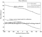
- FIG. 1 illustrates phase difference characteristics of two channels before and after a large-scale antenna array system uses a narrow-band model for calibration under a 400 MHz working bandwidth. It can be seen that only the phase difference at a center frequency point is relatively small, and the phase difference at an edge frequency point of the working bandwidth is relatively large.
- [ ⁇ ] H represents a conjugate transpose operation; and the beamforming gain may be expressed by
- the embodiments of the present disclosure provide a method for calibrating an antenna which may perform multi-channel broadband calibration for a large-scale active antenna array.
- the method compensates, based on a test environment of an OTA, an amplitude and phase error of a channel antenna within a relatively large frequency bandwidth range.
- the full line in FIG. 1 represents a phase difference characteristic of two channels after the calibration method according to the embodiments of the present disclosure is used for calibration.
- the method according to the embodiments of the present disclosure can keep amplitude and phase differences of channels consistent within the working bandwidth of the whole system, thereby effectively ensuring a beamforming effect of the large-scale antenna array for a large-bandwidth signal and ensuring the effectiveness and integrity of a forming function of a device during production detection.
- a phase difference between channels is mainly composed of two parts: the first part is that a channel difference causes an initial phase difference of the center frequency point, i.e., a phase difference compensated by a narrow-band calibration model; and the second part is that a frequency bandwidth causes a phase difference varying with phases, and the phase difference can be effectively compensated through a broadband calibration model.
- the embodiments of the present disclosure compensate and calibrate the amplitude and phase differences of the channels in two parts.
- An initial phase difference corresponding to the center frequency point is compensated to an original theoretical beam weight table, and a phase difference caused by a signal frequency bandwidth is calibrated and compensated via amplitude and phase equalization of a single channel.
- a calibration environment is built at first based on a production scene of a device; an active antenna array is then calibrated under the built calibration environment.
- a production environment of the device may be appropriately transformed to make an electromagnetic environment relatively stable and meet a far field test condition, thereby obtaining the calibration environment used in the embodiments of the present disclosure.
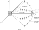
- FIG. 2 exemplarily shows a calibration environment used in the embodiments of the present disclosure.
- the calibration environment includes an active antenna array to be tested, and also includes a test antenna used for calibrating the active antenna array. A distance between the test antenna and the active antenna array meets the far field test condition.
- the test antenna may also be replaced by a terminal.
- the embodiments of the present disclosure are described by taking the test antenna as an example.
- a reception channel beam weight matrix W of the active antenna array includes beam weight vectors corresponding to a plurality of received beam directions (i.e., a plurality of direction angles).
- the beam weight vector of one received beam direction includes beam weights of N reception channels corresponding to the one received beam direction.
- N is the number of the reception channels of the active antenna array, and N is an integer greater than 1.
- test antennas are placed on the X-Y horizontal plane, and correspond to 14 azimuth angles; and 6 test antennas are placed on the Y-Z vertical plane, and correspond to 6 pitching angles.
- One test antenna corresponds to one beam direction region, and one beam direction region corresponds to one direction angle.
- the direction angle is the direction angle of the corresponding test antenna.
- a reception channel initial beam weight matrix may be formed based on active antenna array characteristics.
- q is an integer, 1 ⁇ q ⁇ Q ;
- Q represents the number of received beam directions in the reception channel beam weight matrix, and
- w ( ⁇ q , ⁇ q ) represents a beam weight vector corresponding to the qth received beam direction.
- w ( ⁇ 1 , ⁇ 1 ) represents a beam weight vector corresponding to the received beam direction 1
- w ( ⁇ 2 , ⁇ 2 ) represents a beam weight vector corresponding to the beam direction 2
- the rest can be done in the same manner.
- the dimension number of the beam weight vector w ( ⁇ q , ⁇ q ) in the reception channel initial beam weight matrix W indicates the number of channels.
- FIG. 3 it is a schematic diagram of a reception channel calibration flow for an active antenna array not in accordance with the invention.
- a sequence of a reception calibration signal may be generated at first.
- the reception calibration signal is transmitted by a test antenna to the active antenna array for calibrating the reception channels of the active antenna array.
- F ⁇ ⁇ ⁇ represents fast fourier transform
- F ⁇ 1 ⁇ ⁇ ⁇ represents inverse fast fourier transform
- the flow may include the following.
- the active antenna array receives a reception calibration signal transmitted by a test antenna from a reference beam direction, obtains an amplitude and phase error of each reception channel in the active antenna array, and updates a reception channel beam weight matrix according to the amplitude and phase error of each reception channel.
- N is the number of the reception channels of the active antenna array
- x n ( t ) in the received signal matrix x ( t ) represents the baseband data received by the nth reception channel.
- the amplitudes and the phases between the data (i.e., the above-mentioned N pieces of data) received by the respective reception channels in the active antenna array shall be completely consistent.
- a difference value is a reception channel amplitude and phase error corresponding to the reference beam direction.
- h n E s t x n ⁇ t E x n t x n ⁇ t
- the active antenna array performs multi-channel amplitude and phase error compensation on the reception channel beam weight matrix to obtain an updated reception channel beam weight matrix:
- ⁇ represents a point multiplication operation of respective elements in a vector.
- the active antenna array performs, according to the updated reception channel beam weight matrix, beamforming on the reception calibration signal of the reference beam direction to obtain a reception channel beam gain corresponding to the reference beam direction.
- the active antenna array receives a reception calibration signal transmitted by a test antenna in a first beam direction region, and uses, according to a direction angle of the reception calibration signal from the first beam direction region, a beam weight vector corresponding to the direction angle in the reception channel beam weight matrix to perform beamforming on the reception calibration signal from the first beam direction region to obtain a reception channel beam gain corresponding to the first beam direction region.
- the "first beam direction region” may be any beam region in L beam regions obtained by division.
- the direction angle corresponding to the first beam direction region is different from a direction angle corresponding to the reference beam direction.
- G RXl represents the reception channel beam gain corresponding to the lth beam region
- w ⁇ RX H ⁇ l ⁇ l represents the beam weight vector corresponding to the direction angle ( ⁇ l , ⁇ l ) in the reception channel weight matrix.
- the active antenna array determines a difference value between the reception channel beam gain corresponding to the first beam direction region and the reception channel beam gain corresponding to the reference beam direction, and proceeds to S306 if the difference value is greater than a set gain error threshold, otherwise, proceeds to S305.
- the gain error threshold may be preset.
- the value of the gain error threshold may be determined according to a requirement for the calibration accuracy. If the calibration accuracy is higher, the gain error threshold is smaller.
- the active antenna array determines that the calibration for the beam weight vector corresponding to the first beam direction region in the reception channel beam weight matrix is completed.
- the difference value between the reception channel beam gain corresponding to the first beam region and the reception channel beam gain corresponding to the reference beam direction is less than the set gain error threshold at S304, it is indicated that a reception channel error of the active antenna array is relatively small in all received beam directions corresponding to the first beam direction region, so that the reception beam weight vector corresponding to the first beam direction region in the reception channel beam weight matrix may be kept unchanged, that is, there is no need to perform error calibration for the reception channels in the received beam directions corresponding to the first beam direction region.
- the active antenna array performs at most K reception channel calibration iteration processes, so as to update the beam weight vector, corresponding to the direction angle of the reception calibration signal that is from the first beam direction region, in the reception channel beam weight matrix, thereby realizing calibration for the reception channels of the active antenna array in the received beam directions corresponding to the first beam direction region.
- the reception channel calibration iteration process may refer to FIG. 4 .
- the reception channels of the active antenna array may be all calibrated according to S303 to S306 in the foregoing flow, thereby realizing the calibration for the reception channels of the active antenna array in all the received beam directions.
- FIG. 4 it is a flow diagram of a reception channel calibration iteration process not in accordance with the invention. As shown in the figure, the flow may include the following.
- the active antenna array obtains, according to the reception calibration signal from the first beam direction region, an amplitude and phase error vector of N reception channels of the active antenna array in the first beam direction region.
- the lth beam direction region is taken as an example.
- the active antenna array updates, according to the amplitude and phase error determined in the current iteration process, a received beam weight vector in a received beam direction in the first beam direction region in the reception channel beam weight matrix.
- the lth beam direction region is taken as an example.
- the direction angle of the reception calibration signal of the test antenna from the lth beam direction region is ( ⁇ l , ⁇ l ) .
- the lth beam direction region corresponds to all received beam directions in the following direction angle range: the azimuth angle range is ⁇ l ⁇ P 2 , ⁇ l + P 2 , and the pitching angle range is ⁇ l ⁇ P 2 , ⁇ l + P 2 , where P is the step size.
- the active antenna array updates, according to the amplitude and phase error vector determined in the current iteration process, the beam weight vectors of all the received beams in the direction angle range in the reception beam weight matrix.
- the beam weight vector of beam l i is expressed as w ⁇ l i ⁇ l i .
- the active antenna array uses, according to the direction angle of the reception calibration signal from the first beam direction region, the updated beam weight vector of the corresponding direction angle in the reception channel beam weight matrix to perform beamforming on the reception calibration signal from the first beam direction region to obtain a reception channel beam gain corresponding to the first beam direction region.
- S404 The active antenna array determines whether a gain error between the reception channel beam gain determined in the current iteration process and the reception channel beam gain corresponding to the reference beam direction is greater than a gain error threshold, and proceeds to S406 if the gain error is greater than the gain error threshold, otherwise, S405 is executed.
- S406 It is determined whether the maximum number of iterations has been reached; S407 is executed if the maximum number of iterations has been reached, otherwise, S408 is executed.
- S408 The active antenna array receives a reception calibration signal from the first beam direction region, and S401 is executed to perform the next iteration process.
- a scenario shown in FIG. 2 is taken as an example.
- the active antenna array determines, according to S303 to S304 in FIG. 3 , whether to update the several beam weight vectors within the direction angle range of ( ⁇ , ⁇ ) ⁇ [ ⁇ l -2.5°, ⁇ l +2.5°] ⁇ [ ⁇ l -2.5°, ⁇ l +2.5°] corresponding to this direction angle; and executes, according to the flow shown in FIG.
- a reception channel calibration iteration process if updating is needed until the several beam weight vectors in the direction angle range of ( ⁇ , ⁇ ) ⁇ [ ⁇ l -2.5°, ⁇ l +2.5°] ⁇ [ ⁇ l - 2.5°, ⁇ l +2.5°] are completely updated, or until the updating fails. If updating is not needed, the several beam weight vectors in the direction angle range of ( ⁇ , ⁇ ) ⁇ [ ⁇ l -2.5°, ⁇ l +2.5°] ⁇ [ ⁇ l -2.5° , ⁇ l +2.5°] are kept unchanged.
- reception calibration signals are transmitted in sequence through the corresponding test antennas; and the reception calibration signal transmitted by each test antenna is processed according to the processing flow of reception channel calibration for the calibration signal transmitted by the test antenna 1 until the reception channel calibration is completed for all the beam direction regions.
- the reception calibration signal in the reference beam direction is used to initially update the reception channel beam weight matrix, that is, to initially calibrate the reception channels; then, the beam weight vectors in a plurality of beam directions in a corresponding beam direction region range are updated respectively for different beam direction regions, so as to regionally update the beam weight vectors corresponding to the corresponding regions in the reception channel beam weight matrix, that is, to regionally calibrate the reception channels.
- the method for calibrating the reception channel By adopting the method for calibrating the reception channel according to the above embodiments of the present disclosure, the beamforming functions of related devices of a large-scale active antenna array can be calibrated and detected under a production environment. Compared with the prior art, the method for calibrating the reception channel mainly has the following several advantages.
- the method for calibrating the reception channel according to the embodiments of the present disclosure performs limited detection in vertical and horizontal spatial dimensions only, so that the production detection efficiency is improved.
- the method for calibrating the reception channel according to the embodiments of the present disclosure is independent of a transmission channel calibration process, and can compensate an amplitude-phase error between a transmission channel and a reception channel and improve the beamforming functionality.
- the method for calibrating the reception channel according to the embodiments of the present disclosure is convenient for algorithm realization, and is favorable for being used in an actual production environment.
- the embodiments of the present disclosure also provide a method for calibrating transmission channels for an active antenna array.
- a transmission channel calibration process and the reception channel calibration process of the active antenna array may use the same calibration environment.
- a building method for the calibration environment may refer to the foregoing embodiment, and no more repeated descriptions will be provided here.
- a transmission channel beam weight matrix W of the active antenna array includes beam weight vectors corresponding to a plurality of transmitted beam directions (i.e., a plurality of direction angles).
- the beam weight vector of one transmitted beam direction includes beam weights of N transmission channels corresponding to the one transmitted beam direction.
- N is the number of the transmission channels of the active antenna array, and N is an integer greater than 1.
- a space range corresponding to the Q transmitted beam directions may be divided into L (L is an integer greater than 1, L ⁇ Q) beam direction regions according to the placement positions and the number of the test antennas.
- Each beam direction region corresponds to at least one beam direction
- at least one beam direction region in the L beam direction regions corresponds to a plurality of beam directions.
- the active antenna array may store a correspondence between each beam direction region and the transmitted beam directions.
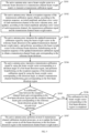
- FIG. 5 it is a schematic diagram of a transmission channel calibration flow for an active antenna array according to the embodiment of the present disclosure.
- a sequence of a transmission calibration signal may be generated at first.
- the transmission calibration signal is transmitted by the active antenna array to a test antenna to calibrate the transmission channels of the active antenna array.
- F[ ⁇ ] represents fast fourier transform
- F -1 [ ⁇ ] represents inverse fast fourier transform
- the flow may include the following.
- the active antenna array uses a beam weight vector in a reference beam direction in the transmission channel beam weight matrix to transmit a transmission calibration signal.
- the active antenna array obtains a reception sequence of the transmission calibration signal, obtains, according to the reception sequence, an initial amplitude and phase error vector of each transmission channel in the active antenna array, and updates, according to the initial amplitude and phase error vector of each transmission channel, the transmission calibration signal and the transmission channel beam weight matrix.
- the process of performing the synchronization and time-frequency domain transformation processing and transmitting the processed frequency domain calibration sequence to the active antenna array may be executed by the test antenna, or executed by other devices. The embodiments of the present disclosure do not limit this.
- An updated time domain sequence of each transmission channel is obtained through inverse fourier transform.
- the active antenna array transmits the updated transmission calibration signal by using the beam weight vector in the reference beam direction in the updated transmission channel beam weight matrix, and performs, according to the beam weight vector in the reference beam direction in the transmission channel beam weight matrix, beamforming on the reception sequence of the updated transmission calibration signal to obtain a transmission channel beam gain corresponding to the reference beam direction.
- the active antenna array transmits the updated transmission calibration signal at the rated nominal power P TX 0 by using the beam weight vector w ⁇ TX (0°,0°), and the time domain sequence of the transmission calibration signal of each transmission channel is s 1 AC , s 2 AC , ... , s N AC .
- the time domain sequence used as a reception sequence of the transmission calibration signal is returned to the active antenna array.
- the active antenna array transmits a transmission calibration signal by using the beam weight vector corresponding to a direction angle of a first beam direction region, and performs beamforming on the reception sequence of the transmission calibration signal by using the beam weight vector corresponding to the direction angle in the transmission channel beam weight matrix, to obtain a transmission channel beamforming gain corresponding to the first beam direction region.
- the "first beam direction region” may be any beam region in L beam regions obtained by division.
- the direction angle corresponding to the first beam direction region is different from a direction angle corresponding to the reference beam direction.
- the lth beam region is taken as an example.
- the active antenna array transmits the updated transmission calibration signal by using the beam weight vector w ⁇ TX ( ⁇ l , ⁇ l ) corresponding to the direction angle ( ⁇ l , ⁇ l ).
- the test antenna corresponding to the direction angle ( ⁇ l , ⁇ l ) receives the transmission calibration signal, and the time domain sequence of the transmission calibration signal received by the test antenna is x TX l t .
- the time domain sequence used as an end sequence of the transmission calibration signal is transmitted to the active antenna array.
- the active antenna array performs beamforming on x TX l t by using the beam weight vector w ⁇ TX ( ⁇ l , ⁇ l ) corresponding to the direction angle ( ⁇ l , ⁇ l ) according to the reception sequence x TX l t of the transmission calibration signal, to obtain a reception channel beam gain corresponding to the lth beam region:
- G TXl 10 log 10 E w ⁇ TX H ⁇ l ⁇ l x TX l t 2 P TX 0
- G TXl represents the transmission channel beam gain corresponding to the lth beam region
- w ⁇ TX H ⁇ l ⁇ l represents the beam weight vector in the direction angle ( ⁇ l , ⁇ l ) in the reception channel weight matrix.
- the test antenna 1 receives the transmission calibration signal, and the time domain sequence of the transmission calibration signal received by the test antenna 1 is transmitted to the active antenna array.
- the active antenna array determines a difference value between the transmission channel beam gain corresponding to the first beam direction region and the transmission channel beam gain corresponding to the reference beam direction, and proceeds to S506 if the difference value is less than or equal to a set gain error threshold, otherwise, proceeds to S507.
- the gain error threshold may be preset.
- the value of the gain error threshold may be determined according to a requirement for the calibration accuracy. If the calibration accuracy is higher, the gain error threshold is smaller.
- the active antenna array determines that the calibration for the beam weight vector corresponding to the first beam direction region in the transmission channel beam weight matrix is completed.
- the difference value between the transmission channel beam gain corresponding to the first beam region and the transmission channel beam gain corresponding to the reference beam direction is less than the set gain error threshold at S505, it is indicated that a transmission channel error of the active antenna array in all transmitted beam directions corresponding to the first beam direction region is relatively small, so that all the beam weight vectors corresponding to the first beam direction region in the transmission channel beam weight matrix may be kept unchanged, that is, there is no need to perform error calibration for the reception channels in the beam directions corresponding to the first beam direction region.
- the active antenna array performs at most K transmission channel calibration iteration processes, so as to update the beam weight vectors in all beam directions in the first beam direction region in the transmission channel beam weight matrix, thereby realizing calibration for the transmission channels of the active antenna array in the beam directions corresponding to the first beam direction region.
- the transmission channel calibration iteration process may refer to FIG. 6 .
- the transmission channels of the active antenna array may be all calibrated according to S504 to S507 in the foregoing flow, thereby realizing the calibration for the transmission channels of the active antenna array in all the transmitted beam directions.
- FIG. 6 it is a flow diagram of a transmission channel calibration iteration process according to the embodiment of the present disclosure. As shown in the figure, the flow may include the following.
- the active antenna array obtains, according to the reception sequence of the transmission calibration signal transmitted by using the beam weight vector corresponding to the direction angle in the first beam direction region, an amplitude and phase error vector of the N transmission channels of the active antenna array in the first beam direction region.
- the lth beam direction region is taken as an example.
- the active antenna array updates, according to the amplitude and phase error vector determined in the current iteration process, the transmission calibration signal and the beam weight vector in the beam direction in the first beam direction region in the transmission channel beam weight matrix.
- the active antenna array may update, according to the formula (22), the transmission calibration signal.
- the time domain sequence of the updated transmission calibration signal of each transmission channel is s 1 ACl , s 2 ACl , ... , s N ACl . Since the first beam direction region corresponds to the beam weight vectors in a plurality of beam directions in the transmission channel beam weight matrix, the active antenna array updates the beam weight vectors in all the beam directions corresponding to the first beam direction region.
- the lth beam direction region is taken as an example, and the direction angle corresponding the lth beam direction region is ( ⁇ l , ⁇ l ) .
- the beam direction region corresponds to all the beam directions in the following direction angle range: the azimuth angle range is ⁇ l ⁇ P 2 , ⁇ l + P 2 , and the pitching angle range is ⁇ l ⁇ P 2 , ⁇ l + P 2 , where P is the step size.
- the active antenna array updates, according to the amplitude and phase error vector determined in the current iteration process, the beam weight vectors in all the beam directions in the direction angle range in the transmission channel beam weight matrix.
- the beam weight vector of beam l i is expressed as w ⁇ l i ⁇ l i .
- the beam weight vector of each beam direction in the direction angle range is updated.
- the active antenna array transmits the updated transmission calibration signal by using the beam weight vector corresponding to the direction angle of the first beam direction region, and performs beamforming on the reception sequence of the transmission calibration signal by using the updated beam weight vector corresponding to the direction angle in the transmission channel beam weight matrix, to obtain a transmission channel beamforming gain corresponding to the first beam direction region.
- the active antenna array determines whether a gain error between the transmission channel beam gain determined in the current iteration process and a transmission beamforming gain corresponding to the reference beam direction is greater than a gain error threshold, and proceeds to S605 if the gain error is less than or equal to the gain error threshold, otherwise, proceeds to S606.
- S606 It is determined whether the maximum number of iterations has been reached; and S607 is executed if the maximum number of iterations has been reached.
- the active antenna array transmits a transmission calibration signal by using the beam weight vector of the direction angle corresponding to the first beam direction region, and obtains a reception sequence of the transmission calibration signal, and proceeds to S601 to enter the next iteration process.
- a scenario shown in FIG. 2 is taken as an example.
- the active antenna array determines, according to S503 to S504 in FIG. 5 , whether to update the several beam weight vectors within the direction angle range of ( ⁇ , ⁇ ) ⁇ [ ⁇ l -2.5°, ⁇ l +2.5°] ⁇ [ ⁇ l - 2.5° , ⁇ l +2.5°] corresponding to this direction angle, and executes, according to the flow shown in FIG.
- a transmission channel calibration iteration process if updating is needed until the several beam weight vectors in the direction angle range of ( ⁇ , ⁇ ) ⁇ [ ⁇ l -2.5°, ⁇ l +2.5°] ⁇ [ ⁇ l - 2.5°, ⁇ l +2.5°] are completely updated, or until the updating fails. If updating is not needed, the several beam weight vectors in the direction angle range of ( ⁇ , ⁇ ) ⁇ [ ⁇ l -2.5°, ⁇ l +2.5°] ⁇ [ ⁇ l -2.5°, ⁇ l +2.5°] are kept unchanged.
- the beam weight vectors corresponding to the direction angles of the corresponding beam direction regions are used to transmit transmission calibration signals in sequence; and according to the reception sequence of the transmission calibration signal, the transmission calibration signal is processed according to the transmission channel calibration flow for the beam direction region 1 in the above flow until the transmission channel calibration is completed for all the beam direction regions.
- the reception sequence of the transmission calibration signal in the reference beam direction is used to initially update the transmission channel beam weight matrix, that is, to initially calibrate the transmission channels; and then, the beam weight vectors in a plurality of beam directions in a corresponding beam direction region range are updated respectively for different beam direction regions, so as to regionally update the beam weight vectors corresponding to the corresponding regions in the transmission channel beam weight matrix, that is, to regionally calibrate the transmission channels.
- the method for calibrating the transmission channel By adopting the method for calibrating the transmission channel according to the above embodiments of the present disclosure, the beamforming functions of related devices of a large-scale active antenna array can be calibrated and detected under a production environment. Compared with the prior art, the method for calibrating the transmission channel mainly has the following several advantages.
- the method for calibrating the transmission channel according to the embodiments of the present disclosure does not need to be carried out in an anechoic chamber, so that the requirement standard and a heavy investment for a test site are lowered.
- the method for calibrating the transmission channel according to the embodiments of the present disclosure performs limited detection in vertical and horizontal spatial dimensions only, so that the production detection efficiency is improved.
- the method for calibrating the transmission channel according to the embodiments of the present disclosure is independent of a reception channel calibration process, and can compensate an amplitude-phase error between a transmission channel and a reception channel and improve the beamforming functionality.
- the method for calibrating the transmission channel according to the embodiments of the present disclosure is convenient for algorithm realization, and is favorable for being used in an actual production environment.
- the embodiments of the present disclosure also provide an apparatus for calibrating an antenna used for calibrating reception channels of an active antenna array.
- FIG. 7 it is a schematic structural diagram of an apparatus for calibrating an antenna used for realizing reception channel calibration not in accordance with the invention.
- the apparatus is applied to an active antenna array.
- a received beam direction range corresponding to a reception channel beam weight matrix of the active antenna array is divided into a plurality of beam direction regions; and one beam direction region corresponds to at least one received beam direction, and at least one beam direction region corresponds to a plurality of received beam directions.
- both an azimuth angle and a pitching angle of the reference beam direction are zero.
- the direction angle of the reference beam direction is different from an azimuth angle corresponding to any beam direction region.
- the apparatus may include: an initial calibration module 701 and a regional calibration module 702
- the initial calibration module 701 is configured to obtain, according to a reception calibration signal received by the active antenna array from the reference beam direction, an initial amplitude and phase error vector of N reception channels of the active antenna array in the reference beam direction, update, according to the initial amplitude and phase error vector, a beam weight vector in each beam direction in the reception channel beam weight matrix, and perform, according to the updated beam weight vector in the reference beam direction in the reception channel beam weight matrix, beamforming on the reception calibration signal in the reference beam direction to obtain a first reception channel beam gain corresponding to the reference beam direction, where the beam weight vector of one received beam direction includes beam weights of the N reception channels corresponding to the one received beam direction, and N is an integer greater than 1.
- the regional calibration module 702 is configured to perform beamforming on a reception calibration signal in a first beam direction region by using a beam weight vector in a corresponding direction angle in the reception channel beam weight matrix according to the reception calibration signal received by the active antenna array from the first beam direction region and a direction angle corresponding to the first beam direction region, to obtain a second reception channel beam gain corresponding to the first beam direction region; and if a gain error between the second reception channel beam gain and the first reception channel beam gain is greater than a gain error threshold, perform at most K reception channel calibration iteration processes according to the reception calibration signal from the first beam direction region, where K is the maximum number of iterations, and the first beam direction region is one of the plurality of beam direction regions.
- the regional calibration module 702 executes:
- the embodiments of the present disclosure also provide an antenna calibration apparatus used for calibrating transmission channels of an active antenna array.
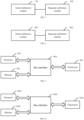
- FIG. 8 it is a schematic structural diagram of an apparatus for calibrating an antenna used for realizing transmission channel calibration according to the embodiment of the present disclosure.
- the apparatus is applied to an active antenna array.
- a transmitted beam direction range corresponding to a transmission channel beam weight matrix of the active antenna array is divided into a plurality of beam direction regions; and one beam direction region corresponds to at least one transmitted beam direction, and at least one beam direction region corresponds to a plurality of transmitted beam directions.
- both an azimuth angle and a pitching angle of the reference beam direction are zero.
- the direction angle of the reference beam direction is different from an azimuth angle corresponding to any beam direction region.
- the apparatus may include: an initial calibration module 801 and a regional calibration module 802.
- the initial calibration module 801 is configured to: obtain an initial amplitude and phase error vector of N transmission channels of the active antenna array according to a reception sequence of a transmission calibration signal transmitted by the active antenna array by using a beam weight vector in a reference beam direction in the transmission channel beam weight matrix, update, according to the initial amplitude and phase error vector, the transmission calibration signal and the beam weight vector in each beam direction in the transmission channel beam weight matrix, transmit the updated transmission calibration signal by using the updated beam weight vector of the reference beam direction in the transmission channel beam weight matrix, and perform, according to the beam weight vector in the reference beam direction, beamforming on the reception sequence of the updated transmission calibration signal to obtain a first transmission channel beam gain corresponding to the reference beam direction, where a beam weight vector of one transmitted beam direction includes beam weights of the N transmission channels corresponding to the one transmitted beam direction, and N is an integer greater than 1.
- the regional calibration module 802 is configured to: after the active antenna array transmits a transmission calibration signal by using a beam weight vector corresponding to a direction angle of a first beam direction region, perform beamforming on a reception sequence of the transmitted transmission calibration signal by using the beam weight vector of the corresponding direction angle in the transmission channel beam weight matrix to obtain a second transmission channel beam gain corresponding to the first beam direction region; and if a gain error between the second transmission channel beam gain and the first transmission channel beam gain is greater than a gain error threshold, perform at most K transmission channel calibration iteration processes, where K is the maximum number of iterations, and the first beam direction region is one of the plurality of beam direction regions.
- the regional calibration module 802 executes:
- the embodiments of the present disclosure also provide a communication apparatus.
- the communication apparatus can realize the reception channel calibration flow in the foregoing embodiment.
- the communication apparatus may include: a processor 901, a memory 902, a transceiver 903 and a bus interface 904.
- the processor 901 is responsible for managing the bus architecture and performing usual processing, and the memory 902 may store data used when the processor 901 performs operations.
- the transceiver 903 is configured to receive and transmit data under the control of the processor 901.
- a bus architecture may include any number of interconnected buses and bridges, and is particularly formed by linking one or more of processors represented by the processor 901 and the various circuits of memories represented by the memory 902 together.
- the bus architecture may also link various other circuits such as peripherals, voltage regulators and power management circuits, which are well known in the art and, therefore, will not be further described herein.
- a bus interface 904 provides an interface.
- the processor 901 is responsible for managing the bus architecture and performing usual processing, and the memory 902 may store data used when the processor 901 performs operations.
- a flow disclosed by the embodiment of the present disclosure may be applied to the processor 901, or implemented by the processor 901.
- each step of a signal processing flow may be completed by integrated logic circuits of hardware in the processor 901 or instructions in the form of software.
- the processor 901 may be a general-purpose processor, a digital signal processor, an application specific integrated circuit, a field programmable gate array or other programmable logic device, a discrete gate or transistor logic device, and a discrete hardware component, and may implement or execute the various methods, steps and logic block diagrams disclosed in the embodiments of the present disclosure.
- the general-purpose processor may be a microprocessor or any conventional processor.
- the steps of the method disclosed in conjunction with the embodiment of the present disclosure may be directly embodied as being executed by a hardware processor, or may be executed and completed by a combination of hardware and software modules in the processor.
- the software module may be located in a mature storage medium in the art, such as a random access memory, a flash memory, a read-only memory, a programmable read-only memory, an electrically erasable programmable memory, and a register.
- the storage medium is located in the memory 902, and the processor 901 reads information in the memory 902 and completes the steps of the signal processing flow in combination with its hardware.
- the processor 901 is used for reading programs in the memory 902 to execute the reception channel calibration flow described in the foregoing embodiments.
- the specific implementation of the flow may refer to the related descriptions of the foregoing embodiments, and no more repeated descriptions will be provided here.
- the embodiments of the present disclosure also provide a communication apparatus.
- the communication apparatus can realize the transmission channel calibration flow in the foregoing embodiment.
- the communication apparatus may include: a processor 1001, a memory 1002, a transceiver 1003 and a bus interface 1004.
- the processor 1001 is responsible for managing the bus architecture and performing usual processing, and the memory 1002 may store data used when the processor 1001 performs operations.
- the transceiver 1003 is configured to receive and transmit data under the control of the processor 1001.
- a bus architecture may include any number of interconnected buses and bridges, and is particularly formed by linking one or more of processors represented by the processor 1001 and the various circuits of memories represented by the memory 1002 together.
- the bus architecture may also link various other circuits such as peripherals, voltage regulators and power management circuits, which are well known in the art and, therefore, will not be further described herein.
- a bus interface 1004 provides an interface.
- the processor 1001 is responsible for managing the bus architecture and performing usual processing, and the memory 1002 may store data used when the processor 1001 performs operations.
- a flow disclosed by the embodiment of the present disclosure may be applied to the processor 1001, or implemented by the processor 1001.
- each step of a signal processing flow may be completed by integrated logic circuits of hardware in the processor 1001 or instructions in the form of software.
- the processor 1001 may be a general-purpose processor, a digital signal processor, an application specific integrated circuit, a field programmable gate array or other programmable logic device, a discrete gate or transistor logic device, and a discrete hardware component, and may implement or execute the various methods, steps and logic block diagrams disclosed in the embodiments of the present disclosure.
- the general-purpose processor may be a microprocessor or any conventional processor.
- the steps of the method disclosed in conjunction with the embodiment of the present disclosure may be directly embodied as being executed by a hardware processor, or may be executed and completed by a combination of hardware and software modules in the processor.
- the software module may be located in a mature storage medium in the art, such as a random access memory, a flash memory, a read-only memory, a programmable read-only memory, an electrically erasable programmable memory, and a register.
- the storage medium is located in the memory 1002, and the processor 1001 reads information in the memory 1002 and completes the steps of the signal processing flow in combination with its hardware.
- the processor 1001 is used for reading programs in the memory 1002 to execute the transmission channel calibration flow described in the foregoing embodiments.
- the specific implementation of the flow may refer to the related descriptions of the foregoing embodiments, and no more repeated descriptions will be provided here.
- the embodiments of the present disclosure further provide a computer-readable storage medium.
- the computer-readable storage medium stores computer-executable instructions.
- the computer-executable instructions are configured to cause a computer to execute the flows executed in the foregoing embodiments.
- These computer program instructions may also be stored in a computer readable memory capable of guiding the computer or other programmable data processing devices to work in a specific manner, thereby making the instructions that are stored in the computer readable memory generate manufactured products that include instruction apparatuses.
- the instruction apparatuses realize the specified functions in one or multiple flows of the flow diagrams and/or one or multiple blocks of the block diagrams.
- These computer program instructions also may be loaded onto the computer or other programmable data processing devices to execute a series of operation steps on the computer or other programmable data processing devices to generate computer implemented processing, so that the instructions executed on the computer or other programmable data processing devices provide steps for realizing the specified functions in one or multiple flows of the flow diagrams and/or one or multiple blocks of the block diagrams.
Landscapes
- Engineering & Computer Science (AREA)
- Computer Networks & Wireless Communication (AREA)
- Signal Processing (AREA)
- Physics & Mathematics (AREA)
- Electromagnetism (AREA)
- General Physics & Mathematics (AREA)
- Mathematical Physics (AREA)
- Variable-Direction Aerials And Aerial Arrays (AREA)
- Radio Transmission System (AREA)
Claims (5)
- Ein Verfahren zum Kalibrieren einer Anordnung aktiver Antennen, wobei ein Übertragungsstrahlrichtungsbereich, der einer Übertragungskanal-Strahlgewichtungsmatrix einer Anordnung aktiver Antennen entspricht, in eine Mehrzahl an Strahlrichtungsbereichen unterteilt ist; ein Strahlrichtungsbereich zumindest einer Übertragungsstrahlrichtung entspricht und eine Mehrzahl an Strahlrichtungsbereichen einer Mehrzahl an Übertragungsstrahlrichtungen entspricht; wobei das Verfahren aufweist:Übertragen (S501), durch die Anordnung aktiver Antennen, eines Übertragungskalibrierungssignals an eine Testantenne unter Verwendung eines Strahlgewichtungsvektors in einer Referenzstrahlrichtung in einer Übertragungskanal-Strahlgewichtungsmatrix; Erhalten (S502) eines anfänglichen Amplituden- und Phasenfehlervektors von N Übertragungskanälen der Anordnung aktiver Antennen gemäß einer Empfangssequenz des Übertragungskalibrierungssignals; Aktualisieren (S502) des Übertragungskalibrierungssignals und eines Strahlgewichtungsvektors in jeder Strahlrichtung in der Übertragungskanal-Strahlgewichtungsmatrix gemäß dem anfänglichen Amplituden- und Phasenfehlervektor; Übertragen (S503) des aktualisierten Übertragungskalibrierungssignals an die Testantenne unter Verwendung des aktualisierten Strahlgewichtungsvektors der Referenzstrahlrichtung in der Übertragungskanal-Strahlgewichtungsmatrix; und Durchführen (S503), gemäß dem Strahlgewichtungsvektor in der Referenzstrahlrichtung, einer Strahlformung an der Empfangssequenz des aktualisierten Übertragungskalibrierungssignals, um eine erste, der Referenzstrahlrichtung entsprechende Übertragungskanal-Strahlverstärkung zu erhalten; wobei ein Strahlgewichtungsvektor einer übertragenen Strahlrichtung Strahlgewichtungen der N Übertragungskanäle aufweist, die der einen übertragenen Strahlrichtung entsprechen, wobei N eine ganze Zahl größer als 1 ist;Übertragen (S504), durch die Anordnung aktiver Antennen, eines Übertragungskalibrierungssignals an die Testantenne unter Verwendung eines einem Richtungswinkel eines ersten Strahlrichtungsbereichs entsprechenden Strahlgewichtungsvektors, und Durchführen (S504) einer Strahlformung an einer Empfangssequenz des gesendeten Übertragungskalibrierungssignals unter Verwendung des Strahlgewichtungsvektors des entsprechenden Richtungswinkels in der Übertragungskanal-Strahlgewichtungsmatrix, um eine zweite, dem ersten Strahlrichtungsbereich entsprechende Übertragungskanal-Strahlverstärkung zu erhalten; undwenn zwischen der zweiten Übertragungskanal-Strahlverstärkung und der ersten Übertragungskanal-Strahlverstärkung ein Verstärkungsfehler größer als ein Verstärkungsfehler-Schwellenwert ist, Durchführen (S507) von höchstens K Übertragungskanal-Kalibrierungsiterationsprozessen; wobei K die maximale Anzahl von Iterationen darstellt und der erste Strahlrichtungsbereich einer der Mehrzahl an Strahlrichtungsbereichen ist;wobei, in jedem Iterationsprozess der höchstens K Übertragungskanal-Kalibrierungsiterationsprozesse, die Anordnung aktiver Antennen ausführt:Erhalten (S601) eines Amplituden- und Phasenfehlervektors der N Übertragungskanäle der Anordnung aktiver Antennen in dem ersten Strahlrichtungsbereich entsprechend der Empfangssequenz des Übertragungskalibrierungssignals, das unter Verwendung des dem Richtungswinkel des ersten Strahlrichtungsbereiches entsprechenden Strahlgewichtungsvektors übertragen wird;Aktualisieren (S602) des Übertragungskalibrierungssignals und des Strahlgewichtungsvektors der Strahlrichtung in dem ersten Strahlrichtungsbereich in der Übertragungskanal-Strahlgewichtungsmatrix gemäß dem in einem aktuellen Iterationsprozess bestimmten Amplituden-und Phasenfehlervektor;Übertragen (S603) des aktualisierten Übertragungskalibrierungssignals an die Testantenne unter Verwendung des Strahlgewichtungsvektors, der dem Richtungswinkel in dem ersten Strahlrichtungsbereich entspricht;Durchführen (S603) einer Strahlformung an der Empfangssequenz des Übertragungskalibrierungssignals unter Verwendung des dem Richtungswinkel entsprechenden Strahlgewichtungsvektors, um eine dem ersten Strahlrichtungsbereich entsprechende Übertragungskanal-Strahlverstärkung zu erhalten; undBestimmen (S604), ob zwischen der in dem aktuellen Iterationsprozess bestimmten Übertragungskanal-Strahlverstärkung und der ersten Übertragungskanal-Strahlverstärkung ein Verstärkungsfehler größer ist als der Verstärkungsfehler-Schwellenwert; wenn der Verstärkungsfehler größer ist als der Verstärkungsfehler-Schwellenwert, Übertragen (S608) des Übertragungskalibrierungssignals an die Testantenne unter Verwendung des Strahlgewichtungsvektors des Richtungswinkels, der dem ersten Strahlrichtungsbereich entspricht, falls die maximale Anzahl von Iterationen nicht erreicht wird, und Durchführen eines nächsten Iterationsprozesses; andernfalls Beenden (S607) des aktuellen Iterationsprozesses.
- Das Verfahren nach Anspruch 1, wobei sowohl ein Azimutwinkel als auch ein Neigungswinkel der Referenzstrahlrichtung Null sind.
- Das Verfahren nach Anspruch 1, wobei sich der Richtungswinkel der Referenzstrahlrichtung von einem Azimutwinkel eines beliebigen Strahlrichtungsbereiches unterscheidet.
- Eine Vorrichtung zum Kalibrieren einer Antenne, die auf eine Anordnung aktiver Antennen angewandt wird, wobei ein Übertragungsstrahlrichtungsbereich, der einer Übertragungskanal-Strahlgewichtungsmatrix der Anordnung aktiver Antennen entspricht, in eine Mehrzahl an Strahlrichtungsbereichen unterteilt ist; ein Strahlrichtungsbereich zumindest einer Übertragungsstrahlrichtung entspricht und eine Mehrzahl an Strahlrichtungsbereichen einer Mehrzahl an Übertragungsstrahlrichtungen entspricht; und die Vorrichtung aufweist:
ein Anfangskalibrierungsmodul (801), ausgebildet zum:Erhalten eines anfänglichen Amplituden- und Phasenfehlervektors von N Übertragungskanälen der Anordnung aktiver Antennen gemäß einer Empfangssequenz eines Übertragungskalibrierungssignals, das von der Anordnung aktiver Antennen übertragen wird, unter Verwendung eines Strahlgewichtungsvektors in einer Referenzstrahlrichtung in der Übertragungskanal-Strahlgewichtungsmatrix,Aktualisieren des Übertragungskalibrierungssignals und des Strahlgewichtungsvektors in jeder Strahlrichtung in der Übertragungskanal-Strahlgewichtungsmatrix gemäß dem anfänglichen Amplituden- und Phasenfehlervektor,Übertragen des aktualisierten Übertragungskalibrierungssignals an eine Testantenne unter Verwendung des aktualisierten Strahlgewichtungsvektors der Referenzstrahlrichtung in der Übertragungskanal-Strahlgewichtungsmatrix, undDurchführen einer Strahlformung an der Empfangssequenz des aktualisierten Übertragungskalibrierungssignals entsprechend dem Strahlgewichtungsvektor in der Referenzstrahlrichtung, um eine erste, der Referenzstrahlrichtung entsprechende Übertragungskanal-Strahlverstärkung zu erhalten, wobei ein Strahlgewichtungsvektor einer Übertragungsstrahlrichtung Strahlgewichtungen der N Übertragungskanäle umfasst, die der einen Übertragungsstrahlrichtung entsprechen, wobei N eine ganze Zahl größer als 1 ist; undein regionales Kalibrierungsmodul (802), ausgebildet, um:wobei, in jedem Iterationsprozess in den höchstens K Übertragungskanal-Kalibrierungsiterationsprozessen, das regionale Kalibrierungsmodul (802) ausgeführt:nachdem die Anordnung aktiver Antennen, unter Verwendung eines einem Richtungswinkel eines ersten Strahlrichtungsbereichs entsprechenden Strahlgewichtungsvektors, ein Übertragungskalibrierungssignal an die Testantenne sendet, unter Verwendung des Strahlgewichtungsvektors des entsprechenden Richtungswinkels in der Übertragungskanal-Strahlgewichtungsmatrix, eine Strahlformung an einer Empfangssequenz des gesendeten Übertragungskalibrierungssignals durchzuführen, um eine dem ersten Strahlrichtungsbereich entsprechende zweite Übertragungskanal-Strahlverstärkung zu erhalten; undwenn zwischen der zweiten Übertragungskanal-Strahlverstärkung und der ersten Übertragungskanal-Strahlverstärkung ein Verstärkungsfehler größer ist als ein Verstärkungsfehler-Schwellenwert, Durchführen von höchstens K Übertragungskanal-Kalibrierungsiterationsprozessen; wobei K die maximale Anzahl von Iterationen ist und der erste Strahlrichtungsbereich einer der Mehrzahl an Strahlrichtungsbereichen ist;Erhalten eines Amplituden- und Phasenfehlervektors der N Übertragungskanäle der Anordnung aktiver Antennen in dem ersten Strahlrichtungsbereich entsprechend der Empfangssequenz des unter Verwendung des Strahlgewichtungsvektors entsprechend dem Richtungswinkel des ersten Strahlrichtungsbereiches übertragenen Übertragungskalibrierungssignals;Aktualisieren des Übertragungskalibrierungssignals und des Strahlgewichtungsvektors der Strahlrichtung in dem ersten Strahlrichtungsbereich in der Übertragungskanal-Strahlgewichtungsmatrix gemäß dem in einem aktuellen Iterationsprozess bestimmten Amplituden-und Phasenfehlervektor;Übertragen des aktualisierten Übertragungskalibrierungssignals an die Testantenne unter Verwendung des dem Richtungswinkel in dem ersten Strahlrichtungsbereich entsprechenden Strahlgewichtungsvektors;Durchführen einer Strahlformung an der Empfangssequenz des Übertragungskalibrierungssignals unter Verwendung des dem Richtungswinkel entsprechenden Strahlgewichtungsvektors, um eine dem ersten Strahlrichtungsbereich entsprechende Übertragungskanal-Strahlverstärkung zu erhalten; undBestimmen, ob ein Verstärkungsfehler zwischen der in dem aktuellen Iterationsprozess bestimmten Übertragungskanal-Strahlverstärkung und der ersten Übertragungskanal-Strahlverstärkung größer als der Verstärkungsfehler-Schwellenwert ist; wenn der Verstärkungsfehler größer als der Verstärkungsfehler-Schwellenwert ist, Übertragen des Übertragungskalibrierungssignals an die Testantenne unter Verwendung des Strahlgewichtungsvektors des Richtungswinkels, der dem ersten Strahlrichtungsbereich entspricht, falls die maximale Anzahl von Iterationen nicht erreicht worden ist, und Durchführen eines nächsten Iterationsprozesses; andernfalls Beenden des aktuellen Iterationsprozesses. - Die Vorrichtung nach Anspruch 4, wobei sowohl ein Azimutwinkel als auch ein Neigungswinkel der Referenzstrahlrichtung Null sind; oder
wobei sich der Richtungswinkel der Referenzstrahlrichtung von einem einem beliebigen Strahlrichtungsbereich entsprechenden Azimutwinkel unterscheidet.
Applications Claiming Priority (2)
| Application Number | Priority Date | Filing Date | Title |
|---|---|---|---|
| CN201810872421.1A CN110798253B (zh) | 2018-08-02 | 2018-08-02 | 一种天线校准方法及装置 |
| PCT/CN2019/097551 WO2020024861A1 (zh) | 2018-08-02 | 2019-07-24 | 一种天线校准方法及装置 |
Publications (3)
| Publication Number | Publication Date |
|---|---|
| EP3832912A1 EP3832912A1 (de) | 2021-06-09 |
| EP3832912A4 EP3832912A4 (de) | 2021-08-25 |
| EP3832912B1 true EP3832912B1 (de) | 2024-10-30 |
Family
ID=69231390
Family Applications (1)
| Application Number | Title | Priority Date | Filing Date |
|---|---|---|---|
| EP19844459.8A Active EP3832912B1 (de) | 2018-08-02 | 2019-07-24 | Verfahren und vorrichtung zur antennenkalibrierung |
Country Status (6)
| Country | Link |
|---|---|
| US (1) | US11171417B2 (de) |
| EP (1) | EP3832912B1 (de) |
| JP (1) | JP7038899B2 (de) |
| KR (1) | KR102363700B1 (de) |
| CN (1) | CN110798253B (de) |
| WO (1) | WO2020024861A1 (de) |
Families Citing this family (15)
| Publication number | Priority date | Publication date | Assignee | Title |
|---|---|---|---|---|
| CN109309533B (zh) * | 2018-09-04 | 2021-05-18 | 华为技术有限公司 | 一种校准方法及设备 |
| GB2579175B (en) * | 2018-11-01 | 2021-01-06 | Leonardo Mw Ltd | An active array antenna with sub-arrays and a method for its calibration |
| CN111447017B (zh) * | 2020-04-09 | 2021-04-30 | 广州通则康威智能科技有限公司 | 阵列天线波束赋形快速测试装置及其测试方法 |
| CN111463575B (zh) * | 2020-04-20 | 2022-02-11 | 上海磐启微电子有限公司 | 基于均匀矩形平面阵的幅相误差自校正装置及方法 |
| US11789118B2 (en) * | 2020-10-23 | 2023-10-17 | Nxp Usa, Inc. | Calibration of a phased array |
| CN112491455B (zh) * | 2021-02-05 | 2021-06-01 | 电子科技大学 | 一种基于阵列单元位置修正的鲁棒性波束赋形方法 |
| US11984659B2 (en) * | 2021-06-23 | 2024-05-14 | Qualcomm Incorporated | Phase pre-compensation for misalignment |
| US11777618B2 (en) * | 2021-09-14 | 2023-10-03 | Hughes Network Systems, Llc | Amplitude and phase calibration for phased array antennas |
| CN115884210A (zh) * | 2021-09-28 | 2023-03-31 | 中国移动通信集团广东有限公司 | 弱覆盖小区优化方法及装置 |
| US12074670B2 (en) * | 2022-02-25 | 2024-08-27 | Qualcomm Incorporated | Methods for beam coordination in a near-field operation with multiple transmission and reception points (TRPS) |
| CN117156451A (zh) * | 2022-05-23 | 2023-12-01 | 大唐移动通信设备有限公司 | 波束权值调整方法、装置、接入网设备和存储介质 |
| CN115060984B (zh) * | 2022-06-13 | 2025-01-14 | 成都华兴大地科技有限公司 | 一种适用于带任意形状天线罩的相控阵天线指向校准方法 |
| CN115765812B (zh) * | 2022-09-29 | 2026-03-31 | 苏州博海创业微系统有限公司 | 一种大规模波束形成矩阵幅度权值预处理方法 |
| CN115588851B (zh) * | 2022-12-12 | 2023-04-11 | 中国电子科技集团公司第十研究所 | 球面相控阵天线的阵元通道相位标校的有效性验证方法 |
| CN115833972B (zh) * | 2023-02-17 | 2023-04-28 | 华清瑞达(天津)科技有限公司 | 对阵列馈电系统输出的目标角位置进行校准的系统及方法 |
Family Cites Families (19)
| Publication number | Priority date | Publication date | Assignee | Title |
|---|---|---|---|---|
| SE522563C2 (sv) * | 2000-02-01 | 2004-02-17 | Ericsson Telefon Ab L M | Kalibreringsmetod för en adaptiv gruppantenn |
| US7272364B2 (en) * | 2002-12-30 | 2007-09-18 | Motorola, Inc. | Method and system for minimizing overlap nulling in switched beams |
| US20090093222A1 (en) | 2007-10-03 | 2009-04-09 | Qualcomm Incorporated | Calibration and beamforming in a wireless communication system |
| US20090288344A1 (en) * | 2008-05-23 | 2009-11-26 | Napoleon Springworks, Inc. | Cable Brake Bracket |
| CN103188009B (zh) * | 2011-12-31 | 2018-01-09 | 中兴通讯股份有限公司 | 信号接收方法及装置 |
| US10164334B2 (en) * | 2013-04-15 | 2018-12-25 | Nokia Solutions And Networks Oy | Antenna system calibration |
| GB2517218B (en) * | 2013-08-16 | 2017-10-04 | Analog Devices Global | Communication unit and method of antenna array calibration |
| KR20170137074A (ko) | 2015-04-10 | 2017-12-12 | 미쓰비시덴키 가부시키가이샤 | 통신 시스템 |
| US9967081B2 (en) | 2015-12-04 | 2018-05-08 | Hon Hai Precision Industry Co., Ltd. | System and method for beamforming wth automatic amplitude and phase error calibration |
| CN106324573A (zh) * | 2016-08-24 | 2017-01-11 | 中国电子科技集团公司第三十八研究所 | 一种适用于平板端射阵列天线的幅相误差校正方法 |
| US20180062260A1 (en) * | 2016-08-26 | 2018-03-01 | Analog Devices Global | Antenna array calibration systems and methods |
| CN107809273A (zh) * | 2016-09-05 | 2018-03-16 | 中兴通讯股份有限公司 | 一种多天线补偿方法及其装置、射频设备 |
| CN106371055B (zh) * | 2016-10-26 | 2018-11-09 | 黑龙江大学 | 远近场宽带混合信号超分辨测向阵列幅相误差估计方法 |
| US10680689B2 (en) | 2017-01-05 | 2020-06-09 | Futurewei Technologies, Inc. | Beam management techniques for beam calibration |
| CN109495189B (zh) | 2017-09-11 | 2020-08-28 | 大唐移动通信设备有限公司 | 一种阵列天线校准方法及装置 |
| CN109802818B (zh) * | 2017-11-17 | 2022-05-10 | 华为技术有限公司 | 通信方法及装置 |
| CN108155958A (zh) * | 2017-11-22 | 2018-06-12 | 西南电子技术研究所(中国电子科技集团公司第十研究所) | 大规模mimo天线阵列远场校准系统 |
| US11177567B2 (en) * | 2018-02-23 | 2021-11-16 | Analog Devices Global Unlimited Company | Antenna array calibration systems and methods |
| JP7731672B2 (ja) * | 2018-06-22 | 2025-09-01 | フラウンホーファー-ゲゼルシャフト・ツール・フェルデルング・デル・アンゲヴァンテン・フォルシュング・アインゲトラーゲネル・フェライン | 方法、測定環境および被試験装置 |
-
2018
- 2018-08-02 CN CN201810872421.1A patent/CN110798253B/zh active Active
-
2019
- 2019-07-24 KR KR1020217006394A patent/KR102363700B1/ko active Active
- 2019-07-24 US US17/265,360 patent/US11171417B2/en active Active
- 2019-07-24 JP JP2021505832A patent/JP7038899B2/ja active Active
- 2019-07-24 WO PCT/CN2019/097551 patent/WO2020024861A1/zh not_active Ceased
- 2019-07-24 EP EP19844459.8A patent/EP3832912B1/de active Active
Also Published As
| Publication number | Publication date |
|---|---|
| US20210257730A1 (en) | 2021-08-19 |
| US11171417B2 (en) | 2021-11-09 |
| JP2021524721A (ja) | 2021-09-13 |
| KR20210040113A (ko) | 2021-04-12 |
| EP3832912A1 (de) | 2021-06-09 |
| WO2020024861A1 (zh) | 2020-02-06 |
| CN110798253B (zh) | 2021-03-12 |
| CN110798253A (zh) | 2020-02-14 |
| JP7038899B2 (ja) | 2022-03-18 |
| EP3832912A4 (de) | 2021-08-25 |
| KR102363700B1 (ko) | 2022-02-15 |
Similar Documents
| Publication | Publication Date | Title |
|---|---|---|
| US11171417B2 (en) | Method and apparatus for calibrating antenna | |
| EP3683984B1 (de) | Verfahren und vorrichtung zur kalibrierung einer gruppenantenne | |
| US10684318B1 (en) | System and method for testing analog beamforming device | |
| EP3349367B1 (de) | Verfahren zur bestimmung eines kommunikationsstrahls und entsprechende vorrichtung | |
| US11962357B2 (en) | Method and system for testing wireless performance of wireless terminal | |
| EP3565134B1 (de) | Antennenkorrekturverfahren und -vorrichtung | |
| EP2533360A1 (de) | Verfahren und vorrichtung zur kalibrierung von antennen | |
| EP3905553A1 (de) | Verfahren und vorrichtung zur prüfung der funkfrequenzleistung eines drahtlosen gerätes und prüfgerät | |
| EP3280168A1 (de) | Verfahren, vorrichtung und kommunikationssystem zur gewinnung von strahlinformationen | |
| Choi et al. | Channel extrapolation for FDD massive MIMO: Procedure and experimental results | |
| Wang et al. | On efficient non-stationary channel emulation in conductive phase matrix setup for massive MIMO performance testing | |
| US12034504B2 (en) | PIM downlink subspace acquisition method | |
| EP3796568B1 (de) | Verfahren zur erkennung von antennenanschlüssen, netzwerkseitiges gerät und computerlesbares speichermedium | |
| US20220182156A1 (en) | Antenna calibration apparatus and antenna calibration method | |
| US20250240103A1 (en) | Calibration of a phase shift matrix for cable-connected testing of a massive multiple-input multiple-output base station | |
| CN102271349B (zh) | 上行干扰抑制合并算法功能测试系统及方法 | |
| Wang et al. | Faulty RIS-aided integrated sensing and communication: Modeling and optimization | |
| Martinez-Ingles et al. | Initial experimental characterization of the millimeter-wave radio channel | |
| WO2024234373A1 (en) | A test method for ecc calculation based on ota 2 tx trp measurement | |
| CN104218983B (zh) | 联合通道校正方法及装置 | |
| CN119483778A (zh) | 空中一致性测试中的虚拟电缆校准 | |
| US20260066965A1 (en) | Creating channels for network testing using network beam information | |
| WO2009089990A1 (de) | Verfahren zur bestimmung der lage eines objekts mit hilfe eines mimo-wlan-funknetzes | |
| CN121985350A (zh) | 空口测试的探头布局优化方法、装置、系统及存储介质 | |
| CN117639965A (zh) | 多通道校正方法、装置、电子设备及存储介质 |
Legal Events
| Date | Code | Title | Description |
|---|---|---|---|
| STAA | Information on the status of an ep patent application or granted ep patent |
Free format text: STATUS: THE INTERNATIONAL PUBLICATION HAS BEEN MADE |
|
| PUAI | Public reference made under article 153(3) epc to a published international application that has entered the european phase |
Free format text: ORIGINAL CODE: 0009012 |
|
| STAA | Information on the status of an ep patent application or granted ep patent |
Free format text: STATUS: REQUEST FOR EXAMINATION WAS MADE |
|
| 17P | Request for examination filed |
Effective date: 20210210 |
|
| AK | Designated contracting states |
Kind code of ref document: A1 Designated state(s): AL AT BE BG CH CY CZ DE DK EE ES FI FR GB GR HR HU IE IS IT LI LT LU LV MC MK MT NL NO PL PT RO RS SE SI SK SM TR |
|
| A4 | Supplementary search report drawn up and despatched |
Effective date: 20210726 |
|
| RIC1 | Information provided on ipc code assigned before grant |
Ipc: H04B 17/12 20150101AFI20210720BHEP Ipc: H01Q 3/00 20060101ALI20210720BHEP |
|
| DAV | Request for validation of the european patent (deleted) | ||
| DAX | Request for extension of the european patent (deleted) | ||
| STAA | Information on the status of an ep patent application or granted ep patent |
Free format text: STATUS: EXAMINATION IS IN PROGRESS |
|
| 17Q | First examination report despatched |
Effective date: 20230509 |
|
| RAP1 | Party data changed (applicant data changed or rights of an application transferred) |
Owner name: DATANG MOBILE COMMUNICATIONS EQUIPMENT CO., LTD. Owner name: CICT MOBILE COMMUNICATION TECHNOLOGY CO., LTD |
|
| GRAP | Despatch of communication of intention to grant a patent |
Free format text: ORIGINAL CODE: EPIDOSNIGR1 |
|
| GRAP | Despatch of communication of intention to grant a patent |
Free format text: ORIGINAL CODE: EPIDOSNIGR1 |
|
| STAA | Information on the status of an ep patent application or granted ep patent |
Free format text: STATUS: GRANT OF PATENT IS INTENDED |
|
| INTG | Intention to grant announced |
Effective date: 20240614 |
|
| GRAS | Grant fee paid |
Free format text: ORIGINAL CODE: EPIDOSNIGR3 |
|
| GRAA | (expected) grant |
Free format text: ORIGINAL CODE: 0009210 |
|
| STAA | Information on the status of an ep patent application or granted ep patent |
Free format text: STATUS: THE PATENT HAS BEEN GRANTED |
|
| AK | Designated contracting states |
Kind code of ref document: B1 Designated state(s): AL AT BE BG CH CY CZ DE DK EE ES FI FR GB GR HR HU IE IS IT LI LT LU LV MC MK MT NL NO PL PT RO RS SE SI SK SM TR |
|
| REG | Reference to a national code |
Ref country code: GB Ref legal event code: FG4D |
|
| REG | Reference to a national code |
Ref country code: CH Ref legal event code: EP |
|
| REG | Reference to a national code |
Ref country code: DE Ref legal event code: R096 Ref document number: 602019061250 Country of ref document: DE |
|
| REG | Reference to a national code |
Ref country code: IE Ref legal event code: FG4D |
|
| REG | Reference to a national code |
Ref country code: LT Ref legal event code: MG9D |
|
| REG | Reference to a national code |
Ref country code: NL Ref legal event code: MP Effective date: 20241030 |
|
| PG25 | Lapsed in a contracting state [announced via postgrant information from national office to epo] |
Ref country code: HR Free format text: LAPSE BECAUSE OF FAILURE TO SUBMIT A TRANSLATION OF THE DESCRIPTION OR TO PAY THE FEE WITHIN THE PRESCRIBED TIME-LIMIT Effective date: 20241030 Ref country code: PT Free format text: LAPSE BECAUSE OF FAILURE TO SUBMIT A TRANSLATION OF THE DESCRIPTION OR TO PAY THE FEE WITHIN THE PRESCRIBED TIME-LIMIT Effective date: 20250228 Ref country code: IS Free format text: LAPSE BECAUSE OF FAILURE TO SUBMIT A TRANSLATION OF THE DESCRIPTION OR TO PAY THE FEE WITHIN THE PRESCRIBED TIME-LIMIT Effective date: 20250228 |
|
| PG25 | Lapsed in a contracting state [announced via postgrant information from national office to epo] |
Ref country code: NL Free format text: LAPSE BECAUSE OF FAILURE TO SUBMIT A TRANSLATION OF THE DESCRIPTION OR TO PAY THE FEE WITHIN THE PRESCRIBED TIME-LIMIT Effective date: 20241030 Ref country code: FI Free format text: LAPSE BECAUSE OF FAILURE TO SUBMIT A TRANSLATION OF THE DESCRIPTION OR TO PAY THE FEE WITHIN THE PRESCRIBED TIME-LIMIT Effective date: 20241030 |
|
| REG | Reference to a national code |
Ref country code: AT Ref legal event code: MK05 Ref document number: 1737946 Country of ref document: AT Kind code of ref document: T Effective date: 20241030 |
|
| PG25 | Lapsed in a contracting state [announced via postgrant information from national office to epo] |
Ref country code: BG Free format text: LAPSE BECAUSE OF FAILURE TO SUBMIT A TRANSLATION OF THE DESCRIPTION OR TO PAY THE FEE WITHIN THE PRESCRIBED TIME-LIMIT Effective date: 20241030 |
|
| PG25 | Lapsed in a contracting state [announced via postgrant information from national office to epo] |
Ref country code: ES Free format text: LAPSE BECAUSE OF FAILURE TO SUBMIT A TRANSLATION OF THE DESCRIPTION OR TO PAY THE FEE WITHIN THE PRESCRIBED TIME-LIMIT Effective date: 20241030 |
|
| PG25 | Lapsed in a contracting state [announced via postgrant information from national office to epo] |
Ref country code: NO Free format text: LAPSE BECAUSE OF FAILURE TO SUBMIT A TRANSLATION OF THE DESCRIPTION OR TO PAY THE FEE WITHIN THE PRESCRIBED TIME-LIMIT Effective date: 20250130 |
|
| PG25 | Lapsed in a contracting state [announced via postgrant information from national office to epo] |
Ref country code: AT Free format text: LAPSE BECAUSE OF FAILURE TO SUBMIT A TRANSLATION OF THE DESCRIPTION OR TO PAY THE FEE WITHIN THE PRESCRIBED TIME-LIMIT Effective date: 20241030 Ref country code: LV Free format text: LAPSE BECAUSE OF FAILURE TO SUBMIT A TRANSLATION OF THE DESCRIPTION OR TO PAY THE FEE WITHIN THE PRESCRIBED TIME-LIMIT Effective date: 20241030 Ref country code: GR Free format text: LAPSE BECAUSE OF FAILURE TO SUBMIT A TRANSLATION OF THE DESCRIPTION OR TO PAY THE FEE WITHIN THE PRESCRIBED TIME-LIMIT Effective date: 20250131 |
|
| PG25 | Lapsed in a contracting state [announced via postgrant information from national office to epo] |
Ref country code: PL Free format text: LAPSE BECAUSE OF FAILURE TO SUBMIT A TRANSLATION OF THE DESCRIPTION OR TO PAY THE FEE WITHIN THE PRESCRIBED TIME-LIMIT Effective date: 20241030 |
|
| PG25 | Lapsed in a contracting state [announced via postgrant information from national office to epo] |
Ref country code: RS Free format text: LAPSE BECAUSE OF FAILURE TO SUBMIT A TRANSLATION OF THE DESCRIPTION OR TO PAY THE FEE WITHIN THE PRESCRIBED TIME-LIMIT Effective date: 20250130 |
|
| PG25 | Lapsed in a contracting state [announced via postgrant information from national office to epo] |
Ref country code: SM Free format text: LAPSE BECAUSE OF FAILURE TO SUBMIT A TRANSLATION OF THE DESCRIPTION OR TO PAY THE FEE WITHIN THE PRESCRIBED TIME-LIMIT Effective date: 20241030 |
|
| PG25 | Lapsed in a contracting state [announced via postgrant information from national office to epo] |
Ref country code: DK Free format text: LAPSE BECAUSE OF FAILURE TO SUBMIT A TRANSLATION OF THE DESCRIPTION OR TO PAY THE FEE WITHIN THE PRESCRIBED TIME-LIMIT Effective date: 20241030 |
|
| PG25 | Lapsed in a contracting state [announced via postgrant information from national office to epo] |
Ref country code: EE Free format text: LAPSE BECAUSE OF FAILURE TO SUBMIT A TRANSLATION OF THE DESCRIPTION OR TO PAY THE FEE WITHIN THE PRESCRIBED TIME-LIMIT Effective date: 20241030 |
|
| PG25 | Lapsed in a contracting state [announced via postgrant information from national office to epo] |
Ref country code: RO Free format text: LAPSE BECAUSE OF FAILURE TO SUBMIT A TRANSLATION OF THE DESCRIPTION OR TO PAY THE FEE WITHIN THE PRESCRIBED TIME-LIMIT Effective date: 20241030 |
|
| PG25 | Lapsed in a contracting state [announced via postgrant information from national office to epo] |
Ref country code: SK Free format text: LAPSE BECAUSE OF FAILURE TO SUBMIT A TRANSLATION OF THE DESCRIPTION OR TO PAY THE FEE WITHIN THE PRESCRIBED TIME-LIMIT Effective date: 20241030 |
|
| PG25 | Lapsed in a contracting state [announced via postgrant information from national office to epo] |
Ref country code: CZ Free format text: LAPSE BECAUSE OF FAILURE TO SUBMIT A TRANSLATION OF THE DESCRIPTION OR TO PAY THE FEE WITHIN THE PRESCRIBED TIME-LIMIT Effective date: 20241030 |
|
| PG25 | Lapsed in a contracting state [announced via postgrant information from national office to epo] |
Ref country code: IT Free format text: LAPSE BECAUSE OF FAILURE TO SUBMIT A TRANSLATION OF THE DESCRIPTION OR TO PAY THE FEE WITHIN THE PRESCRIBED TIME-LIMIT Effective date: 20241030 |
|
| REG | Reference to a national code |
Ref country code: DE Ref legal event code: R097 Ref document number: 602019061250 Country of ref document: DE |
|
| PLBE | No opposition filed within time limit |
Free format text: ORIGINAL CODE: 0009261 |
|
| STAA | Information on the status of an ep patent application or granted ep patent |
Free format text: STATUS: NO OPPOSITION FILED WITHIN TIME LIMIT |
|
| PG25 | Lapsed in a contracting state [announced via postgrant information from national office to epo] |
Ref country code: SE Free format text: LAPSE BECAUSE OF FAILURE TO SUBMIT A TRANSLATION OF THE DESCRIPTION OR TO PAY THE FEE WITHIN THE PRESCRIBED TIME-LIMIT Effective date: 20241030 |
|
| 26N | No opposition filed |
Effective date: 20250731 |
|
| PGFP | Annual fee paid to national office [announced via postgrant information from national office to epo] |
Ref country code: DE Payment date: 20250722 Year of fee payment: 7 |
|
| PGFP | Annual fee paid to national office [announced via postgrant information from national office to epo] |
Ref country code: GB Payment date: 20250722 Year of fee payment: 7 |
|
| PGFP | Annual fee paid to national office [announced via postgrant information from national office to epo] |
Ref country code: FR Payment date: 20250725 Year of fee payment: 7 |
|
| REG | Reference to a national code |
Ref country code: CH Ref legal event code: H13 Free format text: ST27 STATUS EVENT CODE: U-0-0-H10-H13 (AS PROVIDED BY THE NATIONAL OFFICE) Effective date: 20260224 |
|
| PG25 | Lapsed in a contracting state [announced via postgrant information from national office to epo] |
Ref country code: LU Free format text: LAPSE BECAUSE OF NON-PAYMENT OF DUE FEES Effective date: 20250724 |
|
| REG | Reference to a national code |
Ref country code: BE Ref legal event code: MM Effective date: 20250731 |
|
| PG25 | Lapsed in a contracting state [announced via postgrant information from national office to epo] |
Ref country code: BE Free format text: LAPSE BECAUSE OF NON-PAYMENT OF DUE FEES Effective date: 20250731 |
|
| PG25 | Lapsed in a contracting state [announced via postgrant information from national office to epo] |
Ref country code: CH Free format text: LAPSE BECAUSE OF NON-PAYMENT OF DUE FEES Effective date: 20250731 |