EP3832880B1 - System for detecting position sensor faults - Google Patents
System for detecting position sensor faults Download PDFInfo
- Publication number
- EP3832880B1 EP3832880B1 EP20206519.9A EP20206519A EP3832880B1 EP 3832880 B1 EP3832880 B1 EP 3832880B1 EP 20206519 A EP20206519 A EP 20206519A EP 3832880 B1 EP3832880 B1 EP 3832880B1
- Authority
- EP
- European Patent Office
- Prior art keywords
- speed
- observer
- measured
- current
- residual
- Prior art date
- Legal status (The legal status is an assumption and is not a legal conclusion. Google has not performed a legal analysis and makes no representation as to the accuracy of the status listed.)
- Active
Links
- 230000008859 change Effects 0.000 claims description 12
- 230000015654 memory Effects 0.000 claims description 9
- 230000001186 cumulative effect Effects 0.000 claims description 3
- 238000012545 processing Methods 0.000 description 26
- 238000000034 method Methods 0.000 description 25
- 230000004907 flux Effects 0.000 description 11
- 238000013500 data storage Methods 0.000 description 8
- 230000003287 optical effect Effects 0.000 description 7
- 230000000630 rising effect Effects 0.000 description 7
- 230000009466 transformation Effects 0.000 description 5
- 238000006243 chemical reaction Methods 0.000 description 4
- 238000013016 damping Methods 0.000 description 4
- 238000001514 detection method Methods 0.000 description 4
- 230000001360 synchronised effect Effects 0.000 description 4
- 230000003247 decreasing effect Effects 0.000 description 3
- 238000001914 filtration Methods 0.000 description 3
- 230000006870 function Effects 0.000 description 3
- 238000005259 measurement Methods 0.000 description 3
- 239000004065 semiconductor Substances 0.000 description 3
- 230000007704 transition Effects 0.000 description 3
- 238000003491 array Methods 0.000 description 2
- 230000005540 biological transmission Effects 0.000 description 2
- 238000012512 characterization method Methods 0.000 description 2
- 230000008878 coupling Effects 0.000 description 2
- 238000010168 coupling process Methods 0.000 description 2
- 238000005859 coupling reaction Methods 0.000 description 2
- 230000006698 induction Effects 0.000 description 2
- 238000012986 modification Methods 0.000 description 2
- 230000004048 modification Effects 0.000 description 2
- 230000002688 persistence Effects 0.000 description 2
- 230000008569 process Effects 0.000 description 2
- 230000005355 Hall effect Effects 0.000 description 1
- 230000001133 acceleration Effects 0.000 description 1
- 230000009471 action Effects 0.000 description 1
- 230000002411 adverse Effects 0.000 description 1
- 238000013459 approach Methods 0.000 description 1
- 230000015556 catabolic process Effects 0.000 description 1
- 238000004891 communication Methods 0.000 description 1
- 238000006731 degradation reaction Methods 0.000 description 1
- 230000001934 delay Effects 0.000 description 1
- 238000011161 development Methods 0.000 description 1
- 238000003745 diagnosis Methods 0.000 description 1
- 230000007257 malfunction Effects 0.000 description 1
- 238000011084 recovery Methods 0.000 description 1
- 230000002441 reversible effect Effects 0.000 description 1
- 238000007493 shaping process Methods 0.000 description 1
- 239000000126 substance Substances 0.000 description 1
- 238000012546 transfer Methods 0.000 description 1
- 230000001960 triggered effect Effects 0.000 description 1
Images


Classifications
-
- G—PHYSICS
- G01—MEASURING; TESTING
- G01P—MEASURING LINEAR OR ANGULAR SPEED, ACCELERATION, DECELERATION, OR SHOCK; INDICATING PRESENCE, ABSENCE, OR DIRECTION, OF MOVEMENT
- G01P3/00—Measuring linear or angular speed; Measuring differences of linear or angular speeds
- G01P3/42—Devices characterised by the use of electric or magnetic means
- G01P3/44—Devices characterised by the use of electric or magnetic means for measuring angular speed
-
- H—ELECTRICITY
- H02—GENERATION; CONVERSION OR DISTRIBUTION OF ELECTRIC POWER
- H02P—CONTROL OR REGULATION OF ELECTRIC MOTORS, ELECTRIC GENERATORS OR DYNAMO-ELECTRIC CONVERTERS; CONTROLLING TRANSFORMERS, REACTORS OR CHOKE COILS
- H02P21/00—Arrangements or methods for the control of electric machines by vector control, e.g. by control of field orientation
- H02P21/14—Estimation or adaptation of machine parameters, e.g. flux, current or voltage
- H02P21/18—Estimation of position or speed
-
- G—PHYSICS
- G01—MEASURING; TESTING
- G01D—MEASURING NOT SPECIALLY ADAPTED FOR A SPECIFIC VARIABLE; ARRANGEMENTS FOR MEASURING TWO OR MORE VARIABLES NOT COVERED IN A SINGLE OTHER SUBCLASS; TARIFF METERING APPARATUS; MEASURING OR TESTING NOT OTHERWISE PROVIDED FOR
- G01D5/00—Mechanical means for transferring the output of a sensing member; Means for converting the output of a sensing member to another variable where the form or nature of the sensing member does not constrain the means for converting; Transducers not specially adapted for a specific variable
- G01D5/12—Mechanical means for transferring the output of a sensing member; Means for converting the output of a sensing member to another variable where the form or nature of the sensing member does not constrain the means for converting; Transducers not specially adapted for a specific variable using electric or magnetic means
- G01D5/14—Mechanical means for transferring the output of a sensing member; Means for converting the output of a sensing member to another variable where the form or nature of the sensing member does not constrain the means for converting; Transducers not specially adapted for a specific variable using electric or magnetic means influencing the magnitude of a current or voltage
-
- G—PHYSICS
- G05—CONTROLLING; REGULATING
- G05B—CONTROL OR REGULATING SYSTEMS IN GENERAL; FUNCTIONAL ELEMENTS OF SUCH SYSTEMS; MONITORING OR TESTING ARRANGEMENTS FOR SUCH SYSTEMS OR ELEMENTS
- G05B15/00—Systems controlled by a computer
- G05B15/02—Systems controlled by a computer electric
-
- H—ELECTRICITY
- H02—GENERATION; CONVERSION OR DISTRIBUTION OF ELECTRIC POWER
- H02P—CONTROL OR REGULATION OF ELECTRIC MOTORS, ELECTRIC GENERATORS OR DYNAMO-ELECTRIC CONVERTERS; CONTROLLING TRANSFORMERS, REACTORS OR CHOKE COILS
- H02P21/00—Arrangements or methods for the control of electric machines by vector control, e.g. by control of field orientation
- H02P21/06—Rotor flux based control involving the use of rotor position or rotor speed sensors
-
- H—ELECTRICITY
- H02—GENERATION; CONVERSION OR DISTRIBUTION OF ELECTRIC POWER
- H02P—CONTROL OR REGULATION OF ELECTRIC MOTORS, ELECTRIC GENERATORS OR DYNAMO-ELECTRIC CONVERTERS; CONTROLLING TRANSFORMERS, REACTORS OR CHOKE COILS
- H02P21/00—Arrangements or methods for the control of electric machines by vector control, e.g. by control of field orientation
- H02P21/22—Current control, e.g. using a current control loop
Definitions
- the present invention is related to electric drive device systems.
- Electromechanical type of position sensors e.g., resolvers, optical encoders, and hall-effect sensors, are used to obtain the rotor position and/or speed in motor drive systems. Sensors are often subject to failures in harsh environments, such as excessive ambient temperature, super high-speed operation, and other adverse or heavy load conditions.
- sensorless drives including observers are used.
- An observer is embodied in a specific purpose computer, mainly a microcontroller or digital signal processor specifically programmed to execute the observer.
- US 2015/0288306 A1 described a system for controlling an electric motor in which the position of the rotor is estimated based on a current command and a measured current, and the position is used for controlling the motor.
- CN 103259485 A shows a control system for an electric motor in which a fault determining means receives a sensed motor shaft speed and an estimated motor shaft speed.
- the fault determining means comprises a failure residue calculator and a fault diagnosis threshold, the output of both connected to a malfunction judgement means configured to detect a fault of the rotor speed sensor.
- CN 101043194 A1 describes a motor controller with a voltage module operating in high speed conditions and a current module operating in low speed conditions for estimating the motor speed.
- the present invention is defined by the independent Claim.
- FIGS. 1A-10 represent embodiments as described herein.
- Such existing hardware may include one or more Central Processing Units (CPUs), digital signal processors (DSPs), application-specific-integrated-circuits, field programmable gate arrays (FPGAs) computers or the like.
- CPUs Central Processing Units
- DSPs digital signal processors
- FPGAs field programmable gate arrays
- the software implemented aspects of example embodiments are typically encoded on some form of tangible (or recording) storage medium or implemented over some type of transmission medium.
- storage medium may represent one or more devices for storing data, including read only memory (ROM), random access memory (RAM), magnetic RAM, core memory, magnetic disk storage mediums, optical storage mediums, flash memory devices and/or other tangible machine readable mediums for storing information.
- ROM read only memory
- RAM random access memory
- magnetic RAM magnetic RAM
- core memory magnetic disk storage mediums
- optical storage mediums optical storage mediums
- flash memory devices and/or other tangible machine readable mediums for storing information.
- computer-readable medium may include, but is not limited to, portable or fixed storage devices, optical storage devices, and various other mediums capable of storing, containing or carrying instruction(s) and/or data.
- example embodiments may be implemented by hardware, software, firmware, middleware, microcode, hardware description languages, or any combination thereof.
- the program code or code segments to perform the necessary tasks may be stored in a machine or computer readable medium such as a computer readable storage medium.
- a processor or processors When implemented in software, a processor or processors will perform the necessary tasks.
- a pulse width modulation generator (e.g., space vector pulse width modulation) may generate gate signals for switching components in an inverter, which subsequently supplies current to the motor.
- a sensor based control performs over a speed regime as long as the sensor is functioning properly.
- Observers estimate a rotor position and speed that are used in the event of position sensor failure (fault). Each type of observer is sensitive to machine parameters but have different estimation accuracies. Example embodiments exploit differences in observers to improve performance throughout operation of an electric machine (e.g., a motor) in the event of position sensor failure.
- an electric machine e.g., a motor
- a controller is configured to detect a position sensor fault.
- the fault detection performed by the controller includes generation of a fault detection residual and a comparison of the residual to a set threshold.
- the generated fault detection residual is sensitive to the actual fault of the sensor, insensitive to usual disturbance or noise and insensitive to parameter errors and/or non-linearities.
- FIG. 1A illustrates a drive system 100 for controlling a machine such as a motor 155 (e.g., an interior permanent magnet synchronous motor (IPMSM)) or another alternating current machine.
- a motor 155 e.g., an interior permanent magnet synchronous motor (IPMSM)
- IPMSM interior permanent magnet synchronous motor
- the drive system 100 may include additional features that are not illustrated in FIG. 1A .
- the drive system 100 may include a rotor magnet temperature estimation module, a current shaping module, and a terminal voltage feedback module.
- the features shown in FIG. 1A are illustrated for the convenience of describing the drive system 100 and it should be understood that the drive system 100 should not be limited to the features shown in FIG. 1A .
- the drive system 100 includes electronic modules, software modules, or both.
- the drive system 100 includes an electronic data processing system 101 to support storing, processing or execution of software instructions of one or more software modules.
- the electronic data processing system 101 is indicated by the dashed lines in FIG. 1A , is shown in greater detail in FIG. 1B and may also be referred to as a controller.
- the data processing system 101 is coupled to an inverter circuit 150.
- the inverter circuit 150 may be a three-phase inverter.
- the inverter circuit 150 includes a semiconductor drive circuit that drives or controls switching semiconductors (e.g., insulated gate bipolar transistors (IGBT) or other power transistors) to output control signals for the motor 155.
- IGBT insulated gate bipolar transistors
- the inverter circuit 150 is coupled to the motor 155.
- the motor 155 is associated with sensors 180a and 180c.
- the sensors 180a and 180c are referred to as current transducers. However, it should be understood that the sensors 180a and 180c may be another type of current sensor.
- the current transducers 180a and 180c and the motor 155 are coupled to the data processing system 101 to provide feedback data (e.g., current feedback data, such as phase current values la and Id), raw position signals, among other possible feedback data or signals, for example. While only two current transducers 180a and 180c are shown, it should be understood that the drive system 100 may implement three current transducers.
- the data processing system 101 includes a speed regulator 105, a base torque lookup table (LUT) 110, a torque processor 115, a ratio calculator 120, a q-axis current (Iq) command LUT 125, a d-axis current (Id) command LUT 130, a current regulator 135, converters 140, 160, a pulse width generation module 145 and a position and speed processor170.
- a speed regulator 105 includes a speed regulator 105, a base torque lookup table (LUT) 110, a torque processor 115, a ratio calculator 120, a q-axis current (Iq) command LUT 125, a d-axis current (Id) command LUT 130, a current regulator 135, converters 140, 160, a pulse width generation module 145 and a position and speed processor170.
- the data processing system 101 including the speed regulator 105, the base torque lookup table (LUT) 110, the torque processor 115, the ratio calculator 120, the q-axis current (Iq) command LUT 125, the d-axis current (Id) command LUT 130, the current regulator 135, the converters 140, 160, the pulse width generation module 145 and the position and speed processor 170 may be implemented as hardware, such as a processor, firmware or hardware executing software as a special purpose machine.
- CPUs Central Processing Units
- DSPs digital signal processors
- ASICs application-specific-integrated-circuits
- FPGAs field programmable gate arrays
- CPUs, DSPs, ASICs and FPGAs may generally be referred to as processors and/or microprocessors.
- the processor is configured as special purpose machine to execute the software to perform the functions of the speed regulator 105, the base torque lookup table (LUT) 110, the torque processor 115, the ratio calculator 120, the q-axis current (Iq) command LUT 125, the d-axis current (Id) command LUT 130, the converters 140, 160, the pulse width generation module 145 and the position and speed processor 170.
- a data processor 264 is specifically programmed to execute the speed regulator 105, the base torque lookup table (LUT) 110, the torque processor 115, the ratio calculator 120, the q-axis current (Iq) command LUT 125, the d-axis current (Id) command LUT 130, the current regulator 135, the converters 140, 160, the pulse width generation module 145 and the position and speed processor 170, as will be described in FIG. 1B .
- a speed regulator 105 receives input data representing a difference between a control rotor speed ⁇ cont and a command rotor speed ⁇ r ⁇ as input.
- the command rotor speed ⁇ r ⁇ may be input by a controller (shown as 266 in FIG. 1B ) via a vehicle data bus 118.
- a controller shown as 266 in FIG. 1B
- the speed regulator 105 converts the received input data into a feedforward torque TFF.
- the feedforward torque TFF may also be referred to as a torque command.
- command refers to a target value.
- the base torque LUT 110 determines a base torque value Tbase based on the control rotor speed ⁇ cont.
- base torque values are respectively associated with discrete speed points with a nominal dc bus voltage level.
- the two-dimensional base torque LUT 110 is established from a motor characterization procedure.
- each rotor shaft speed has a maximum output torque, which is defined as the base torque at that speed.
- the base torque may also be referred to as peak torque.
- the base torque LUT 110 outputs the associated base torque value as the base torque value Tbase to the torque processor 115.
- the torque processor 115 receives the base torque value Tbase and the feedforward torque TFF.
- the feedforward torque TFF may be in Nm.
- the torque processor 115 is configured to determine an absolute value of the feedforward torque TFF.
- the torque processor 115 is configured to convert the absolute value of the feedforward torque TFF into a percentage Torq_Perc of the base torque value Tbase.
- the torque processor 115 outputs the percentage Torq_Perc to the q-axis current (Iq) command LUT 125 and the d-axis current (Id) command LUT 130.
- the position and speed processor 170 sends the control rotor speed ⁇ cont to the ratio calculator 120.
- the ratio calculator 120 is configured to receive the measured operating dc bus voltage value.
- the measured operating dc bus voltage value is provided by a voltage sensor 185 which measures the DC bus in the inverter circuit 150.
- the inverter circuit 150 is powered by a direct current (dc) voltage bus.
- the ratio Tratio is output by the ratio calculator 120 to the d-q axis current command LUTs 125 and 130.
- the q-axis current command (Iq) LUT 125 and the d-axis current (Id) command LUT 130 are configured to receive the ratio Tratio.
- the q-axis current command LUT 125 and the d-axis current command LUT 130 store q-axis and d-axis current commands, respectively, each of which is associated with a pair of ratio and torque percentage values.
- the development of the q-axis current command LUT 125 and the d-axis current command LUT 130 may be done using any known method.
- the d-q axis current refers to the direct axis current and the quadrature axis current as applicable in the context of vector-controlled alternating current machines, such as the motor 155.
- the d-axis current command LUT 130 is configured to output a d-axis current command I d ⁇ that is associated with the received torque percentage Torq_Perc and the ratio Tratio. As shown in FIG. 1A , the d-axis current command I d ⁇ is output to the current regulator 135.
- the q-axis current command LUT 125 is configured to output a q-axis current command I q ⁇ that is associated with the received torque percentage Torq_Perc and ratio Tratio.
- I d ⁇ and I q ⁇ are current commands for a stator of the motor 155.
- q-axis current command LUT 125 and d-axis current command LUT 130 are illustrated and described as LUTs, it should be understood that the q-axis current command LUT 125 and d-axis current command LUT 130 may be implemented as a set of equations that relate respective torque commands to corresponding direct and quadrature axes currents, or a set of rules (e.g., if-then rules) that relates respective torque commands to corresponding direct and quadrature axes currents.
- the q-axis current command I q ⁇ is output to the current regulator 135.
- the current regulator 135 is capable of communicating with the pulse-width modulation (PWM) generation module 145 (e.g., space vector PWM generation module).
- PWM pulse-width modulation
- the current regulator 135 receives respective d-q axis current commands (e.g., I d ⁇ and I q ⁇ ) and measured d-q axis currents (e.g., Ids and Iqs) for the stator and outputs synchronous d-q axis voltage commands v ds e and v qs e using any known method such as current feed forward compensation.
- the converter 140 receives the synchronous d-q axis voltage commands v ds e and v qs e and performs an inverse Park transformation to generate ⁇ - ⁇ axis voltage commands ⁇ ⁇ ⁇ and ⁇ ⁇ ⁇ (the ⁇ - ⁇ axis voltage commands ⁇ ⁇ ⁇ and ⁇ ⁇ ⁇ may also be identified as stationary command values v ds ⁇ and v qs * ). While at least one example embodiment is described using the ⁇ - ⁇ axis, it should be understood that example embodiments may be implemented using the d-q axis or three phase representation of a control vector.
- the PWM generation module 145 converts the ⁇ axis voltage and ⁇ axis voltage data (voltage commands ⁇ ⁇ * and ⁇ ⁇ * ) from two phase data representations into three phase representations (e.g., three phase voltage representations, such as va*, vb* and vc*) for control of the motor 155, for example.
- Outputs of the PWM generation module 145 are coupled to the inverter circuit 150.
- the inverter circuit 150 includes power electronics, such as switching semiconductors to generate, modify and control pulse-width modulated signals or other alternating current signals (e.g., pulse, square wave, sinusoidal, or other waveforms) applied to the motor 155.
- the PWM generation module 145 provides inputs to a driver stage within the inverter circuit 150.
- An output stage of the inverter circuit 150 provides a pulse-width modulated voltage waveform or other voltage signal for control of the motor 155.
- the inverter circuit 150 is powered by the direct current (dc) voltage bus voltage VDC.
- the current transducers 180a, 180c measure two of three phase current data la and Ic, respectively, applied to the motor 155. It should be understood that an additional current transducer may also measure a third phase current data Ib.
- the converter 160 may apply a Clarke transformation or other conversion equations (e.g., certain conversion equations that are suitable and are known to those of ordinary skill in the art) to convert the measured three-phase representations of current into two-phase representations of current based on the current data la and Ib from the current transducers 180a, 180c and a control rotor position ⁇ cont from the position and speed processor 170.
- a Clarke transformation or other conversion equations e.g., certain conversion equations that are suitable and are known to those of ordinary skill in the art
- the output of the converter 160 module (Ids, Iqs) is coupled to the current regulator 135 and the position and speed processor.
- reference frame refers to a coordinate system used to represent and measure properties such as position (e.g., angular rotational position), velocity, torque, electrical parameters, and orientation of the rotor of the motor, the stator of the motor, or both.
- position e.g., angular rotational position
- rotational velocity, torque, electrical parameters and orientation of the rotor, the stator, or both are observed from a stationary observer's point of view.
- a stationary reference frame may refer to the case where the reference frame is aligned with the stator of the motor, or where the d-axis and the q-axis do not rotate with the rotor.
- a stationary reference frame is mutually exclusive to a rotating reference frame.
- the instantaneous stator currents of a multi-phase motor can be expressed as a single complex stator current vector in a Cartesian coordinate system. If a Park transform or a similar transform is applied to the complex stator current vector, the reference frame has direct axis (d-axis) and quadrature axis (q-axis) components that rotate with rotor flux position (e.g., local maximum in magnetic field). For a motor with permanent magnets attached to the rotor the rotor flux position does not change with respect to the rotor, as opposed to where electromagnets are used in certain rotors.
- d-axis direct axis
- q-axis quadrature axis
- the position and speed processor 170 may apply a Park transformation or other conversion equations (e.g., certain conversion equations that are suitable and are known to those of ordinary skill in the art) to convert the measured three-phase representations of current into two-phase representations of current (measured currents, I ⁇ , I ⁇ ) based on the current data Ia and Ic from the current transducers 180a, 180c, using a converter 160 (shown in FIG. 2 ).
- Park transformation or other conversion equations e.g., certain conversion equations that are suitable and are known to those of ordinary skill in the art
- a position sensor 172 generates data representative of a position of the rotor of the motor 155 and provides the data to the position and speed processor 170.
- the position sensor 172 may be any type of known position sensor including an encoder and a resolver.
- the position and speed processor 170 receives the measured position ⁇ meas, the measured currents Ia, Ic and the voltage commands ⁇ q * and ⁇ d * . Based on the measured currents Ia, Ic and the voltage commands ⁇ q * and ⁇ d * , the position and speed processor 170 is configured to output the control position ⁇ cont to the converter 160, as will be described in greater detail in FIG. 2 .
- the position and speed processor 170 also converts the estimated rotor position ⁇ re ⁇ into the estimated rotor speed ⁇ r .
- the electronic data processing system 101 includes an electronic data processor 264, a data bus 262, a data storage device 260, and one or more data ports (268, 270, 272 and 274).
- the data processor 264, the data storage device 260 and one or more data ports are coupled to the data bus 262 to support communications of data between or among the data processor 264, the data storage device 260 and one or more data ports.
- the data processor 264 may include an electronic data processor, a digital signal processor, microprocessor, a microcontroller, a programmable logic array, a logic circuit, an arithmetic logic unit, an application specific integrated circuit, a digital signal processor, a proportional-integral-derivative (PID) controller, or another data processing device.
- PID proportional-integral-derivative
- the data storage device 260 may include any magnetic, electronic, or optical device for storing data.
- the data storage device 260 may include an electronic data storage device, an electronic memory, non-volatile electronic random access memory, one or more electronic data registers, data latches, a magnetic disc drive, a hard disc drive, an optical disc drive, or the like.
- the storage device 260 may be a read only memory (ROM), random access memory (RAM), magnetic RAM, core memory, magnetic disk storage medium, optical storage medium, flash memory device and/or other tangible machine readable medium for storing information.
- the data storage device 260 may store the algorithms implemented in the speed regulator 105, the base torque lookup table (LUT) 110, the torque processor 115, the ratio calculator 120, the q-axis current (Iq) command LUT 125, the d-axis current (Id) command LUT 130, the current regulator 135, the converter 140, pulse width generation module 145, the converter 160 and the position and speed processor 170 to be executed by the data processor 264.
- the data processor 264 may access the data storage device 260 and execute in the speed regulator 105, the base torque lookup table (LUT) 110, the torque processor 115, the ratio calculator 120, the q-axis current (Iq) command LUT 125, the d-axis current (Id) command LUT 130, the current regulator 135, the converter 140, pulse width generation module 145, the converter 160 and the position and speed processor 170 via the data bus 262.
- LUT base torque lookup table
- Id d-axis current
- the data processor 264 may access the data storage device 260 and execute in the speed regulator 105, the base torque lookup table (LUT) 110, the torque processor 115, the ratio calculator 120, the q-axis current (Iq) command LUT 125, the d-axis current (Id) command LUT 130, the current regulator 135, the converter 140, pulse width generation module 145, the converter 160 and the position and speed processor 170 via the data bus 262.
- the data ports include a first data port 268, a second data port 270, a third data port 272 and a fourth data port 274, although any suitable number of data ports may be used.
- Each data port may include a transceiver and buffer memory, for example.
- each data port may include any serial or parallel input/output port.
- the first data port 268 is coupled to the vehicle data bus 118.
- the vehicle data bus 118 is coupled to a controller 266.
- the second data port 270 may be coupled to the inverter circuit 150; the third data port 272 may be coupled to the voltage sensor 185; and the fourth data port 274 may be coupled to the transducers 180a and 180c.
- the speed regulator 105 is associated with or supported by the first data port 268 of the electronic data processing system 101.
- the first data port 268 may be coupled to a vehicle data bus 118, such as a controller area network (CAN) data bus.
- vehicle data bus 118 may provide data bus messages with torque commands to the speed regulator 105 via the first data port 268.
- the operator of a vehicle may generate the torque commands via a user interface, such as a throttle, a pedal, the controller 266, or other control device.
- FIG. 2 illustrates a position and speed processor.
- the position and speed processor 170 includes a position and speed processing unit 205, a position and speed observer 210 and a fault detector 215.
- the position and speed processing unit 205, the position and speed observer 210 and the fault detector 215 be implemented as hardware, such as a processor, firmware or hardware executing software as a special purpose machine.
- the position and speed processing unit 205 receives the output of the position sensor 172 and generates a measured speed ⁇ meas and a measured rotor position ⁇ meas.
- the position sensor 172 is an incremental encoder with an index that produces A/B digital pulses.
- the A/B are digital pulses that provide direction and a number of pulses (e.g., 512 pulses each) per rotor revolution. Once per mechanical revolution the index line (Z) pulses to provide an absolute position.
- the position and speed processing unit 205 accounts for sensing delays, converts the A/B/Z measurements to the corresponding position in radians or degrees or other engineering units.
- a sensorless position estimator may be used instead of the position sensor 172.
- the fault detector 215 may include a filter such as a cumulative sum (CUSUM) filter 216.
- the CUSUM filter 216 may filter a first residual.
- the first residual may be generated by the fault detector 215 and is an error between a filtered speed (an observer speed) ⁇ obs and the command rotor speed ⁇ r * .
- a second residual may be generated by the fault detector 215 using a measured position. The first and second residuals will be discussed in further detail below.
- the position and speed observer 210 receives the measured d-q axis currents in the stationary frame (e.g., Ids and Iqs) and measured d-q axis voltages in the stationary frame (Vds and Vqs) for the stator (or ⁇ - ⁇ axis voltage commands ⁇ ⁇ * and ⁇ ⁇ * ) and generates an observer speed ⁇ obs and an observer position ⁇ obs based on the measured d-q axis currents (e.g., Ids and Iqs) and measured d-q axis voltages (Vd and Vq).
- the measured d-q axis currents in the stationary frame e.g., Ids and Iqs
- Vds and Vq measured d-q axis voltages
- the position and speed observer 210 includes a first stage 210a and a second stage 210b.
- the first stage 210a uses a current model or voltage model based on a model select signal from the fault detector 215. More specifically, for estimated speeds from zero to a desired speed (e.g., a low speed threshold), the position and speed observer 210 uses a current model to determine the estimated position ⁇ obs and an estimated speed ⁇ r . For estimated speeds above the desired speed, the position and speed observer 210 uses a voltage model determine the estimated position ⁇ obs and the estimated speed ⁇ r .
- the desired speed may be a threshold set by a user based on empirical data and may vary depending on implementation.
- the second stage 210b receives the estimated speed ⁇ r the first stage 210a and determines the observer speed ⁇ obs of the rotor based on the estimated speed ⁇ r .
- FIGS. 3A-3B illustrate example embodiments of the first stage 210a. More specifically, FIG. 3A illustrates a mechanical model of the first stage 210a. FIG. 3B illustrates a current model of the first stage according to at least one example embodiment. FIG. 3C illustrates a voltage model of the first stage according to at least one example embodiment.
- FIG. 3A illustrates a mechanical model 210a1 of the first stage 210a according to at least one example embodiment.
- the mechanical model 210a1 may be implemented in the digital domain.
- the first stage 210a1 receives a mechanical position ⁇ m.
- the first stage 210a1 determines a difference ⁇ from the mechanical position ⁇ m and the current observer position ⁇ obs at a subtractor 302.
- the difference ⁇ is applied to an observer gain Kso on a first path 304a and is applied to a first z-transform 303 (1/(1-z-1)) and then another observer gain Kiso on a second path 304b.
- the product of the difference ⁇ and the gain Kso from the first path 304a is summed with the product of the difference ⁇ , 1/(1-z-1) and the gain Kiso from the second path 304b and a value B at an adder 305.
- the output of the adder 305 is a shaft torque disturbance value Tdo1.
- the torque value Tdo1 is summed with a feed-forward torque TFF at an adder 307.
- the adder 307 also subtracts a product of an average speed estimate from the observer ⁇ o 1 ⁇ and a physical estimation of damping bpo (po refers to physical damping of an observer) from the shaft torque disturbance value Tdo1 and the feed-forward torque TFF to generate an output of the adder 307.
- the output of the adder 307 is multiplied by 1/Jpo at 309 to generate a derivative of the speed estimate from the observer ⁇ 01 ⁇ , where Jpo is an estimate of a true inertia (motor inertia plus load inertia).
- the derivate of the speed estimate from the observer ⁇ 01 ⁇ then goes through a second z-transform 311 (1/(1-z-1)), a third z-transform 312 ((1+z-1)/2) and then a fourth z-transform 313 (1/(1-z-1)). More specifically, the output of the second z-transform 311 is an estimated rotor speed ⁇ r ⁇ and is input to the third z-transform 312 as well as the second stage 210b1. The output of the third z-transform 312 average speed estimate from the observer ⁇ o 1 ⁇ and is input to the fourth z-transform 313. Using the output of the third z-transform 312 the fourth z-transform 313 generates the observer position ⁇ obs. The observer position ⁇ obs is feedback to the subtractor 302.
- the output of the third z-transform 312 (the speed estimate from the observer ⁇ o 1 ⁇ ) is multiplied by an observer gain bpo at 315.
- the product of the output of the third z-transform 312 and physical estimation of damping bpo is fed to the adder 307.
- the speed estimate from the observer ⁇ o 1 ⁇ is also fed based to a subtractor 317.
- the mechanical position ⁇ m is also input to a subtractor 319 and a fifth z-transform 321 (1/z).
- the subtractor 319 determines a difference between the mechanical position ⁇ m and the 1/z transform of the mechanical position ⁇ m.
- the difference outputted by the subtractor 319 is input to the subtractor 317.
- the subtractor 317 determines a difference between the output of the subtractor 319 and the speed estimate from the observer ⁇ o 1 ⁇ and outputs the difference where it is multiplied by a gain bo of the observer to generate the value B.
- FIG. 3B illustrates a current model of the first stage according to at least one example embodiment. As shown in FIG. 3B , the current model illustrated is for an induction type machine.
- the current Iqds is multiplied by e -j ⁇ r and then multiplied by (Lm/ ⁇ r) at 335 where Lm is a magnetizing inductance, ⁇ r is a rotor time constant (ratio of rotor inductance and rotor resistance), and ⁇ qdr is a flux linkage.
- Lm is a magnetizing inductance
- ⁇ r is a rotor time constant (ratio of rotor inductance and rotor resistance)
- ⁇ qdr is a flux linkage.
- the output of the Laplace transform 345 is a flux linkage ⁇ qdr in the rotor reference frame (subscript r refers to rotor reference frame).
- the flux linkage ⁇ qdr is feedback to a 1/ rr transformation at 350.
- the output of the transformation 350 is input to the subtractor 340.
- a rotor position ⁇ r for an induction machine is the mechanical position.
- the arc tangent of the rotor flux ⁇ qdr estimated by current and voltage models are a synchronous position ⁇ e.
- Subtracting a slip position ⁇ slip from ⁇ e generates ⁇ r, which is the same as the mechanical position ⁇ m.
- a slip speed ⁇ slip is integrated.
- FIG. 3C illustrates a voltage model of the first stage according to at least one example embodiment.
- the current Iqds is multiplied by a stator resistance rs at 355.
- a subtractor 360 determines a difference between the voltage Vqds command and the product of the current Iqds and the stator resistance rs.
- a Laplace transform 365 is applied to the difference determined by the subtractor 360 to generate a stationary flux linkage ⁇ qds.
- the current Iqds is multiplied by a total stator inductance Ls ((Lm+ LIs) where LIs is the stator leakage inductance) and a coupling factor ⁇ ((1 - Lm2)/(Ls*Lr)) at 370.
- a subtractor 375 determines a difference between the stationary flux linkage ⁇ qds and the product of the current Iqds, the total stator inductance Ls and the coupling factor ⁇ .
- the difference generated by the subtractor 375 is multiplied by a ratio of the total rotor inductance Lr to the total magnetic inductance Lm at 380 to generate the flux linkage ⁇ qdr.
- FIGS. 4A-4B illustrate example embodiments of a second stage of the position and speed observer shown in FIG. 2 .
- the second stage may be a Luenberger observer 210b1.
- the Luenberger observer 210b1 may be used to filter the estimated rotor speed ⁇ r ⁇ from the first stage 210a1 with zero or reduced lag.
- the Luenberger observer 210b1 is implemented in the digital domain.
- the Luenberger observer 210b1 represents the mechanical model of the system.
- a subtractor 400 determines a difference between the estimated rotor speed ⁇ r ⁇ and a current observed speed ⁇ obs.
- a first z-transform 405 (1/(1-z-1)) is applied to the difference determined by the subtractor and the difference determined by the subtractor is multiplied by bo at 415. The result of the first z-transform is then multiplied by the gain Kso at 410.
- the product of 410 and the product of 415 are added by an adder 418.
- the sum of the product of 410 and the product of 415 produced by the adder 418 is a disturbance torque value Td.
- the disturbance torque value Td is added with the feed forward torque TFF at an adder 420.
- the adder 420 also subtracts a product of the current observed speed ⁇ obs and the physical estimation of damping bpo from the sum of the sum of the product of 410, the product of 415 and the feed forward torque TFF.
- the result of the adder 420 is multiplied by (1/Jpo) at 425 to generate a speed derivative ⁇ .
- a second z-transform 430 (1/(1-z-1)) is applied to the speed derivative ⁇ to generate a new observed speed ⁇ obs.
- the new observed speed ⁇ obs is feedback to be multiplied by bpo at 435 and then to the adder 420.
- the second stage may be a Luenberger observer 210b2.
- the Luenberger observer 210b2 may be used to filter the estimated rotor speed ⁇ r ⁇ from the first stage 210a1 with zero or reduced lag.
- the Luenberger observer 210b2 is implemented in the digital domain.
- the Luenberger observer 210b2 represents the mechanical model of the system.
- FIG. 5 illustrates a method of controlling. The method includes determining a position sensor fault and determining a mode of providing a position value and a speed value.
- the method may be performed by the fault detector 215.
- the fault detector 215 starts performing the method.
- the fault detector 215 resets a first residual N and a second residual M.
- the first residual N and the second residual M are both set to zero.
- the fault detector 215 obtains the measured speed ⁇ meas and position ⁇ meas from the position and speed processing unit 205 and obtains the observer speed ⁇ obs and observer position ⁇ obs from the position and speed observer 210.
- the fault detector 215 updates the first residual N and the second residual M based on the measured speed ⁇ meas and position ⁇ meas.
- FIG. 6A illustrates a method of updating the first residual N.
- the fault detector 215 determines a difference between a speed command (i.e., a command rotor speed ⁇ r * ) and a filtered speed.
- the CUSUM filter 216 filters the difference between the speed command and a current filtered speed. The filtering performed by the CUSUM filter 216 is shown in more detail in FIG. 6B . The generation of the filtered speed is also described in FIG. 6B .
- the CUSUM filter updates the input by including the difference determined at S605.
- a first order filter may be used to smooth noisy signals.
- the filter gain G can be increased.
- increasing G may result in more lag, as it will cause a lag in the residual generation, which in turn causes lag in a switchover to a sensorless mode for position and speed estimation.
- the CUSUM filter 216 keeps a mean unchanged until there is sufficient statistical evidence that there has been a real change in the signal that is being filtered (e.g., the difference between the speed command and the filtered speed).
- the CUSUM filter 216 updates a counter value k.
- the CUSUM filter 216 determines a variance of measured rotor speeds of a number of samples.
- the CUSUM filter 660 compares the CUMSUM generated at S655 with a first threshold value.
- the first threshold value may be based on empirical data and/or set by a user.
- the first threshold value may be in terms of sigma, e.g., a value of 2 sigma specifies a 95% confidence and 3 sigma specifies 99.7% confidence. If the CUMSUM is greater than the first threshold, the CUSUM filter 216 updates a filtered error value at S665.
- the fault detector 215 determines whether the filtered error value determined at S665 is less than a second threshold value.
- the second threshold value may be based on empirical data and/or set by a user.
- the second threshold value may be application specific. If the error is less than the threshold Th-H, the fault detector 215 increments the first residual N and proceeds to S625. In some example embodiments, the fault detector 215 increments the first residual N by two. In other example embodiments, the amount of incrementing is application specific and set to a desired value based on empirical data.
- the fault detector determines whether the error is decreasing. If the fault detector 215 determines the error is decreasing, the fault detector decrements the first residual N. If the fault detector 215 determines the error is not decreasing, the fault detector 215 increases the first residual at S630.
- FIG. 6C illustrates a method of updating the second residual M.
- the fault detector 215 determines whether the measured position (e.g., ⁇ meas) is changing at S670. If the fault detector 215 determines that the measured position is changing at S670, the fault detector 215 determines whether the difference between the speed command and the filtered speed (determined at S605) and the speed command are greater than zero at S675. If the fault detector 215 determines that the difference between the speed command and the filtered speed (determined at S605) and the speed command are greater than zero, the fault detector 215 increments the second residual M at S685. In some example embodiments, the second residual is incremented by one. If the fault detector 215 determines that the position is not changing or that at least one of the difference between the speed command and the filtered speed (determined at S605) and the speed command are not greater than zero, the fault detector 215 maintains the second residual M at S680.
- the fault detector 215 determines that the position is not changing or that at least one of the difference between the speed command and the filtered speed (determined at S605) and
- the fault detector 215 determines whether the first residual N is more than a third threshold value and whether the second residual M is more than a fourth threshold value.
- the fault detector 215 switches the control to the sensorless control.
- Position and speed synchronizing scheme is used to enable a jitter free and/or reduced jitter transfer to the sensorless control.
- the fault detector 215 continues to use a sensor based control mode at S525. More specifically, the position and speed processor 170 continues to output the measured position ⁇ meas as the control position ⁇ cont and the measured speed ⁇ meas as the control speed ⁇ cont.
- the fault detector 215 determines a voltage position offset ⁇ offset_v between the control position ⁇ cont and the observer position ⁇ obs_v using the voltage model and a current position offset ⁇ offset_i between the control position ⁇ cont and the observer position ⁇ obs_i using the current.
- the fault detector 215 performs a transition from a sensor based control mode to a sensorless based control mode at S530. More specifically, the position and speed processor 170 uses the observer position ⁇ obs as the control position ⁇ cont and the observer speed ⁇ obs as the control speed ⁇ cont.
- the third and fourth threshold values may be set by a user based on empirical data and/or inertia and acceleration/declaration requirements.
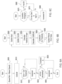
- FIG. 7 illustrates a method of transitioning from a sensor based control to a sensorless based control and using the sensorless measurements according to at least one example embodiment. More specifically, FIG. 7 illustrates an example embodiment of S530, S535 and S540.
- the fault detector 215 generates a rising edge for an enable signal when the fault detector 215 determines the first residual N is more than the third threshold value and/or the second residual M is less than the second threshold value.
- the fault detector determines a voltage position offset ⁇ offset_v between the control position ⁇ cont and an observer position ⁇ obs_v using the voltage model and a current position offset ⁇ offset_i between the control position ⁇ cont and an observer position ⁇ obs_i using the current model at S710. Because a first residual N and a second residual M are utilized, switchover is enabled before an appreciable degradation of the measured position ⁇ meas.
- the fault detector selects an observer.
- the fault detector 215 determines whether the control speed ⁇ cont is greater than a speed threshold (e.g., 500 revolutions per minute (RPM)). If the fault detector 215 determines that the control speed ⁇ cont is equal to or less than the speed threshold, the fault detector 215 sets a flag Vorl to 1, and selects the current model, indicating that the current model should be used in the first stage 210a.
- a speed threshold e.g., 500 revolutions per minute (RPM)
- the fault detector 215 may synchronize the observer position ⁇ obs_i with the measured position ⁇ meas. More specifically, the fault detector 215 uses a monostable circuit (e.g., having a 50 ⁇ s sample time) to adjust the observer position ⁇ obs_i by the current position offset ⁇ offset_i to match the measured position ⁇ meas.
- a monostable circuit e.g., having a 50 ⁇ s sample time
- the monostable circuit is a trigger generator.
- the rising edge of the enable signal triggers the rising edge monostable which in turn enables a determination of the current position offset ⁇ offset_i.
- the current position offset ⁇ offset_i is added to the observed position ⁇ obs_i to synchronize it the measured position ⁇ meas.
- a falling edge for the enable signal is generated causing the falling edge monostable to trigger.
- the fault detector 215 determines that the control speed ⁇ cont is greater than the speed threshold, the fault detector 215 sets a flag Vorl to 0 and selects the voltage model at S715, indicating that the voltage model should be used in the first stage 210a.
- the fault detector 215 may synchronize the observer position ⁇ obs_v from the voltage model with the measured position ⁇ meas. More specifically, the fault detector 215 uses the monostable circuit to adjust the observer position ⁇ obs_v by the current position offset ⁇ offset_v to match the measured position ⁇ meas. The rising edge of the enable signal triggers the rising edge monostable which in turn enables a determination of the voltage position offset ⁇ offset_v. The voltage position offset ⁇ offset_v is added to the observed position ⁇ obs_v to synchronize it the measured position ⁇ meas.
- the fault detector 215 uses the observer position of the selected observer ⁇ obs plus the observed speed ⁇ obs*Ts, where Ts is a control loop delay for calculating position, as the new control position ⁇ cont and the observer speed of the selected observer ⁇ obs as the new control speed ⁇ cont.
- Ts is a control loop delay for calculating position
- the fault detector 215 uses the observer position of the selected observer ⁇ obs as the new control position ⁇ cont and the observer speed of the selected observer ⁇ obs as the new control speed ⁇ cont.
- the fault detector 215 may determine whether the sensor has recovered. S540 may be performed at a control rate.
- the control rate may also be referred to as a task rate, a step rate or an execution rate and is based on the clock rate of the controller.
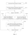
- FIG. 8 illustrates method of determining whether a sensor has recovered according to an example embodiment.
- the fault detector 215 determines whether a speed error is less than an error threshold.
- the speed error may be a difference between the command rotor speed ⁇ r * and the measured speed ⁇ meas. If the fault detector 215 determines the speed error is equal to or more than a speed error threshold, the fault detector does not generate a falling edge for the enable signal at S807 (i.e., does not permit a switch of the control position ⁇ cont and the control speed ⁇ cont from the observed position ⁇ obs and the observed speed ⁇ obs to the measured position ⁇ meas and the measured speed ⁇ meas). If the fault detector 215 determines the speed error is less than a speed error threshold, the method proceeds to S810.
- the fault detector 215 determines whether a position change is within a range. More specifically, the fault detector determines a degrees/sec change ⁇ (also referred to as a position change) between the measured rotor speed ⁇ meas[k] using the measured position ⁇ meas[k] and a previous measured rotor speed ⁇ meas[k-1] using the measured position ⁇ meas[k-1]. If the degrees/sec change ⁇ calculated from the measured position ⁇ meas is outside a desired range, the fault detector 215 does not enable generate a falling edge for the enable signal at S807.
- a degrees/sec change ⁇ also referred to as a position change
- the fault detector 215 determines whether a persistence counter limit has been reached.
- the persistence counter counts a number of times the speed error and position change are acceptable (yes for S805 and S810). If the counter limit has not been reached, the fault detector 215 proceeds to S807. If the counter limit has been reached, the fault detector 215 proceeds to S825.
- the fault detector 215 determines whether there is a change in the speed command. If the fault detector 215 determines there is no change in the speed command, the fault detector 215 generates a falling edge for the enable signal at S827 (i.e., permits a switch of the control position ⁇ cont and the control speed ⁇ cont from the observed position ⁇ obs and the observed speed ⁇ obs to the measured position ⁇ meas and the measured speed ⁇ meas). If the fault detector 215 determines there is a change in the speed command, the method proceeds back to S805.
- the enable signal at S827 i.e., permits a switch of the control position ⁇ cont and the control speed ⁇ cont from the observed position ⁇ obs and the observed speed ⁇ obs to the measured position ⁇ meas and the measured speed ⁇ meas.
- the method proceeds to S715 and referring back to FIG. 5 , the fault detector 215 uses the observer position ⁇ obs as the control position ⁇ cont and the observer speed ⁇ obs as the control speed ⁇ cont at S535.
- the fault detector 215 determines that sensor has recovered at S540, the fault detector 215 transitions the control position ⁇ cont and the control speed ⁇ cont from the observed position ⁇ obs and the observed speed ⁇ obs to the measured position ⁇ meas and the measured speed ⁇ meas at S545.
- FIG. 9 illustrates an example embodiment of transitioning to the measured position and measured speed as the control position and control speed.
- the fault detector 215 At S905, the fault detector 215 generates a falling edge for the enable signal when the fault detector 215 determines the sensor has recovered at S540. Upon generation of the falling edge, the fault detector determines a position offset ⁇ offset between the control position ⁇ cont and the measured position ⁇ meas at S910.
- the fault detector 215 may synchronize the observer position ⁇ obs with the measured position ⁇ meas. More specifically, the fault detector 215 uses a monostable circuit (e.g., having a 50 ⁇ s sample time) to adjust the measured position ⁇ meas by the position offset ⁇ offset to match the observed position ⁇ obs. More specifically, the fault detector 215 uses the monostable circuit to adjust the measured position ⁇ meas by the position offset ⁇ offset to match the observed position ⁇ obs.
- the falling edge of the enable signal triggers a falling edge monostable which in turn enables a determination of the position offset ⁇ offset.
- the position offset ⁇ offset is added to the measured position ⁇ meas to synchronize it the observed position ⁇ obs.
- the fault detector 215 uses the measured position ⁇ meas plus the observed speed ⁇ obs*Ts, where Ts is a control loop delay for calculating position, as the new control position ⁇ cont and the measured speed ⁇ meas as the new control speed ⁇ cont.
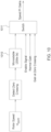
- FIG. 10 illustrates a flow chart of dynamically adjusting proportional integral (PI) gains of the controller 101 according to an example embodiment.
- the speed regulator 105 includes a proportional-integral-derivative (PID) controller to generate the feed forward torque value TFF.
- PID proportional-integral-derivative
- the controller 101 detects zero crossings of the control speed ⁇ cont. Upon detection of a zero crossing a monostable circuit 1010 is triggered.
- the monostable circuit 1010 provides an input to a switch 1011.
- the switch 1011 also receives the enable signal, a normal gain and the speed PI gains at the zero crossing.
- the switch 1011 dynamically lowers the PI gains to minimize transients when the enable signal is high (i.e., when and after a rising edge is generated).
Description
- The present invention is related to electric drive device systems.
- Electromechanical type of position sensors, e.g., resolvers, optical encoders, and hall-effect sensors, are used to obtain the rotor position and/or speed in motor drive systems. Sensors are often subject to failures in harsh environments, such as excessive ambient temperature, super high-speed operation, and other adverse or heavy load conditions.
- As an alternative to sensors, sensorless drives including observers are used. An observer is embodied in a specific purpose computer, mainly a microcontroller or digital signal processor specifically programmed to execute the observer.
-
US 2015/0288306 A1 described a system for controlling an electric motor in which the position of the rotor is estimated based on a current command and a measured current, and the position is used for controlling the motor. -
CN 103259485 A shows a control system for an electric motor in which a fault determining means receives a sensed motor shaft speed and an estimated motor shaft speed. The fault determining means comprises a failure residue calculator and a fault diagnosis threshold, the output of both connected to a malfunction judgement means configured to detect a fault of the rotor speed sensor. -
CN 101043194 A1 describes a motor controller with a voltage module operating in high speed conditions and a current module operating in low speed conditions for estimating the motor speed. -
US 2013/0289934 A1 describes in the prior art discussion a Luenberger observer system for speed sensorless approaches for speed estimation of AC machines. - The present invention is defined by the independent Claim.
- Example embodiments will be more clearly understood from the following detailed description taken in conjunction with the accompanying drawings.
FIGS. 1A-10 represent embodiments as described herein. -
FIG. 1A illustrates a drive system for controlling an IPM machine; -
FIG. 1B illustrates a data processing system of the drive system ofFIG. 1A ; -
FIG. 2 illustrates a position and speed processor; -
FIGS. 3A-3C illustrate a first stage of a position and speed observer shown inFIG. 2 ; -
FIGS. 4A-4B illustrate a second stage of the position and speed observer shown inFIG. 2 ; -
FIG. 5 illustrates a method of controlling; -
FIG. 6A illustrates a method of updating the first residual N; -
FIG. 6B illustrates a method of filtering; -
FIG. 6C illustrates a method of updating the second residual M; -
FIG. 7 illustrates a method of transitioning from a sensor based control to a sensorless based control and a method of selecting an observer model; -
FIG. 8 illustrates a method of determining whether a sensor has recovered; -
FIG. 9 illustrates an embodiment of transitioning to a measured position and a measured speed as a control position and a control speed; and -
FIG. 10 illustrates a flow chart of dynamically adjusting proportional integral (PI) gains of a controller. - Example embodiments will now be described more fully with reference to the accompanying drawings in which some example embodiments are illustrated.
- Accordingly, while example embodiments are capable of various modifications and alternative forms, embodiments thereof are shown by way of example in the drawings and will herein be described in detail. It should be understood, however, that there is no intent to limit example embodiments to the particular forms disclosed, but on the contrary, example embodiments are to cover all modifications, equivalents, and alternatives falling within the scope of the claims. Like numbers refer to like elements throughout the description of the figures.
- It will be understood that, although the terms first, second, etc. may be used herein to describe various elements, these elements should not be limited by these terms. These terms are only used to distinguish one element from another. For example, a first element could be termed a second element, and, similarly, a second element could be termed a first element, without departing from the scope of example embodiments. As used herein, the term "and/or" includes any and all combinations of one or more of the associated listed items.
- It will be understood that when an element is referred to as being "connected" or "coupled" to another element, it can be directly connected or coupled to the other element or intervening elements may be present. In contrast, when an element is referred to as being "directly connected" or "directly coupled" to another element, there are no intervening elements present. Other words used to describe the relationship between elements should be interpreted in a like fashion (e.g., "between" versus "directly between," "adjacent" versus "directly adjacent," etc.).
- As used herein, the singular forms "a," "an" and "the" are intended to include the plural forms as well, unless the context clearly indicates otherwise. It will be further understood that the terms "comprises," "comprising," "includes" and/or "including," when used herein, specify the presence of stated features, integers, steps, operations, elements and/or components, but do not preclude the presence or addition of one or more other features, integers, steps, operations, elements, components and/or groups thereof.
- It should also be noted that in some alternative implementations, the functions/acts noted may occur out of the order noted in the figures. For example, two figures shown in succession may in fact be executed substantially concurrently or may sometimes be executed in the reverse order, depending upon the functionality/acts involved.
- Unless otherwise defined, all terms (including technical and scientific terms) used herein have the same meaning as commonly understood by one of ordinary skill in the art to which example embodiments belong. It will be further understood that terms, e.g., those defined in commonly used dictionaries, should be interpreted as having a meaning that is consistent with their meaning in the context of the relevant art and will not be interpreted in an idealized or overly formal sense unless expressly so defined herein.
- Portions of example embodiments and corresponding detailed description are presented in terms a processor specifically programmed to execute software, or algorithms and symbolic representations of operation on data bits within a computer memory. These descriptions and representations are the ones by which those of ordinary skill in the art effectively convey the substance of their work to others of ordinary skill in the art. An algorithm, as the term is used here, and as it is used generally, is conceived to be a self-consistent sequence of steps leading to a result. The steps are those requiring physical manipulations of physical quantities. Usually, though not necessarily, these quantities take the form of optical, electrical, or magnetic signals capable of being stored, transferred, combined, compared, and otherwise manipulated. It has proven convenient at times, principally for reasons of common usage, to refer to these signals as bits, values, elements, symbols, characters, terms, numbers, or the like.
- In the following description, illustrative embodiments will be described with reference to acts and symbolic representations of operations (e.g., in the form of flowcharts) that may be implemented as program modules or functional processes including routines, programs, objects, components, data structures, etc., that perform particular tasks or implement particular abstract data types and may be implemented using existing hardware. Such existing hardware may include one or more Central Processing Units (CPUs), digital signal processors (DSPs), application-specific-integrated-circuits, field programmable gate arrays (FPGAs) computers or the like.
- It should be borne in mind, however, that all of these and similar terms are to be associated with the appropriate physical quantities and are merely convenient labels applied to these quantities. Unless specifically stated otherwise, or as is apparent from the discussion, terms such as "processing" or "computing" or "calculating" or "determining" or "displaying" or the like, refer to the action and processes of a computer system, or similar electronic computing device, that manipulates and transforms data represented as physical, electronic quantities within the computer system's registers and memories into other data similarly represented as physical quantities within the computer system memories or registers or other such information storage, transmission or display devices.
- Note also that the software implemented aspects of example embodiments are typically encoded on some form of tangible (or recording) storage medium or implemented over some type of transmission medium. As disclosed herein, the term "storage medium", "computer readable storage medium" or "non-transitory computer readable storage medium" may represent one or more devices for storing data, including read only memory (ROM), random access memory (RAM), magnetic RAM, core memory, magnetic disk storage mediums, optical storage mediums, flash memory devices and/or other tangible machine readable mediums for storing information. The term "computer-readable medium" may include, but is not limited to, portable or fixed storage devices, optical storage devices, and various other mediums capable of storing, containing or carrying instruction(s) and/or data.
- Furthermore, example embodiments may be implemented by hardware, software, firmware, middleware, microcode, hardware description languages, or any combination thereof. When implemented in software, firmware, middleware or microcode, the program code or code segments to perform the necessary tasks may be stored in a machine or computer readable medium such as a computer readable storage medium. When implemented in software, a processor or processors will perform the necessary tasks.
- In controlling a motor, a pulse width modulation generator (e.g., space vector pulse width modulation) may generate gate signals for switching components in an inverter, which subsequently supplies current to the motor.
- In a motor drive system, there are instances where the system uses rotor position information.
- In some motor drive systems, a sensor based control performs over a speed regime as long as the sensor is functioning properly.
- Observers estimate a rotor position and speed that are used in the event of position sensor failure (fault). Each type of observer is sensitive to machine parameters but have different estimation accuracies. Example embodiments exploit differences in observers to improve performance throughout operation of an electric machine (e.g., a motor) in the event of position sensor failure.
- A controller is configured to detect a position sensor fault. The fault detection performed by the controller includes generation of a fault detection residual and a comparison of the residual to a set threshold. The generated fault detection residual is sensitive to the actual fault of the sensor, insensitive to usual disturbance or noise and insensitive to parameter errors and/or non-linearities.
- In accordance with an example embodiment,
FIG. 1A illustrates adrive system 100 for controlling a machine such as a motor 155 (e.g., an interior permanent magnet synchronous motor (IPMSM)) or another alternating current machine. - It should be understood that the
drive system 100 may include additional features that are not illustrated inFIG. 1A . For example, thedrive system 100 may include a rotor magnet temperature estimation module, a current shaping module, and a terminal voltage feedback module. The features shown inFIG. 1A are illustrated for the convenience of describing thedrive system 100 and it should be understood that thedrive system 100 should not be limited to the features shown inFIG. 1A . - The
drive system 100 includes electronic modules, software modules, or both. In an example embodiment, thedrive system 100 includes an electronicdata processing system 101 to support storing, processing or execution of software instructions of one or more software modules. The electronicdata processing system 101 is indicated by the dashed lines inFIG. 1A , is shown in greater detail inFIG. 1B and may also be referred to as a controller. - The
data processing system 101 is coupled to aninverter circuit 150. Theinverter circuit 150 may be a three-phase inverter. Theinverter circuit 150 includes a semiconductor drive circuit that drives or controls switching semiconductors (e.g., insulated gate bipolar transistors (IGBT) or other power transistors) to output control signals for themotor 155. In turn, theinverter circuit 150 is coupled to themotor 155. Themotor 155 is associated withsensors - Throughout the specification, the
sensors sensors - The
current transducers motor 155 are coupled to thedata processing system 101 to provide feedback data (e.g., current feedback data, such as phase current values la and Id), raw position signals, among other possible feedback data or signals, for example. While only twocurrent transducers drive system 100 may implement three current transducers. - The
data processing system 101 includes aspeed regulator 105, a base torque lookup table (LUT) 110, atorque processor 115, aratio calculator 120, a q-axis current (Iq)command LUT 125, a d-axis current (Id)command LUT 130, acurrent regulator 135,converters width generation module 145 and a position and speed processor170. - The
data processing system 101, including thespeed regulator 105, the base torque lookup table (LUT) 110, thetorque processor 115, theratio calculator 120, the q-axis current (Iq)command LUT 125, the d-axis current (Id)command LUT 130, thecurrent regulator 135, theconverters width generation module 145 and the position andspeed processor 170 may be implemented as hardware, such as a processor, firmware or hardware executing software as a special purpose machine. When thedata processing system 101 is hardware, such hardware may include one or more Central Processing Units (CPUs), digital signal processors (DSPs), application-specific-integrated-circuits (ASICs), field programmable gate arrays (FPGAs) computers or the like configured as special purpose machines to perform the functions of thedata processing system 101. CPUs, DSPs, ASICs and FPGAs may generally be referred to as processors and/or microprocessors. - In the event that the
data processing system 101 is a processor executing software, the processor is configured as special purpose machine to execute the software to perform the functions of thespeed regulator 105, the base torque lookup table (LUT) 110, thetorque processor 115, theratio calculator 120, the q-axis current (Iq)command LUT 125, the d-axis current (Id)command LUT 130, theconverters width generation module 145 and the position andspeed processor 170. For example, adata processor 264 is specifically programmed to execute thespeed regulator 105, the base torque lookup table (LUT) 110, thetorque processor 115, theratio calculator 120, the q-axis current (Iq)command LUT 125, the d-axis current (Id)command LUT 130, thecurrent regulator 135, theconverters width generation module 145 and the position andspeed processor 170, as will be described inFIG. 1B . - In an example embodiment, a
speed regulator 105 receives input data representing a difference between a control rotor speed ωcont and a command rotor speed
- The command rotor speed

FIG. 1B ) via avehicle data bus 118. For example, if an operator wants themotor 155 to run at 5,000 RPM, the operator inputs 5,000 RPM into the controller and thevehicle data bus 118 inputs the command rotor speed
data processing system 101. Thespeed regulator 105 converts the received input data into a feedforward torque TFF. The feedforward torque TFF may also be referred to as a torque command. - While the term command is used throughout the specification, it should be understood that command refers to a target value.
- The
base torque LUT 110 determines a base torque value Tbase based on the control rotor speed ωcont. - From the control rotor speed ωcont, base torque values are respectively associated with discrete speed points with a nominal dc bus voltage level. In other words, the two-dimensional
base torque LUT 110 is established from a motor characterization procedure. During the IPM motor characterization procedure, each rotor shaft speed has a maximum output torque, which is defined as the base torque at that speed. Thus, the base torque may also be referred to as peak torque. - The
base torque LUT 110 outputs the associated base torque value as the base torque value Tbase to thetorque processor 115. - The
torque processor 115 receives the base torque value Tbase and the feedforward torque TFF. The feedforward torque TFF may be in Nm. - The
torque processor 115 is configured to determine an absolute value of the feedforward torque TFF. Thetorque processor 115 is configured to convert the absolute value of the feedforward torque TFF into a percentage Torq_Perc of the base torque value Tbase. Thetorque processor 115 outputs the percentage Torq_Perc to the q-axis current (Iq)command LUT 125 and the d-axis current (Id)command LUT 130. - In addition to sending the control rotor speed ωcont to the
base torque LUT 110, the position andspeed processor 170 sends the control rotor speed ωcont to theratio calculator 120. - In addition to receiving the control rotor speed ωcont, the
ratio calculator 120 is configured to receive the measured operating dc bus voltage value. The measured operating dc bus voltage value is provided by avoltage sensor 185 which measures the DC bus in theinverter circuit 150. Theinverter circuit 150 is powered by a direct current (dc) voltage bus. Theratio calculator 120 adjusts the operating DC bus voltage VDC by thevoltage sensor 185 to the detected operating rotor shaft speed ratio as follows:
where Tratio is the adjusted detected operating DC bus voltage to the detected operating rotor shaft speed ratio and Y is a coefficient. For example, the coefficient Y may be 0.9. The ratio Tratio is output by theratio calculator 120 to the d-q axiscurrent command LUTs - The q-axis current command (Iq)
LUT 125 and the d-axis current (Id)command LUT 130 are configured to receive the ratio Tratio. The q-axiscurrent command LUT 125 and the d-axiscurrent command LUT 130 store q-axis and d-axis current commands, respectively, each of which is associated with a pair of ratio and torque percentage values. The development of the q-axiscurrent command LUT 125 and the d-axiscurrent command LUT 130 may be done using any known method. - The d-q axis current refers to the direct axis current and the quadrature axis current as applicable in the context of vector-controlled alternating current machines, such as the
motor 155. - The d-axis
current command LUT 130 is configured to output a d-axis current command
FIG. 1A , the d-axis current command
current regulator 135. - The q-axis
current command LUT 125 is configured to output a q-axis current command
- It should be understood that


motor 155. - While the q-axis
current command LUT 125 and d-axiscurrent command LUT 130 are illustrated and described as LUTs, it should be understood that the q-axiscurrent command LUT 125 and d-axiscurrent command LUT 130 may be implemented as a set of equations that relate respective torque commands to corresponding direct and quadrature axes currents, or a set of rules (e.g., if-then rules) that relates respective torque commands to corresponding direct and quadrature axes currents. - As shown in
FIG. 1A , the q-axis current command
current regulator 135. - The
current regulator 135 is capable of communicating with the pulse-width modulation (PWM) generation module 145 (e.g., space vector PWM generation module). Thecurrent regulator 135 receives respective d-q axis current commands (e.g.,


- The
converter 140 receives the synchronous d-q axis voltage commands


- In an example embodiment, the
PWM generation module 145 converts the α axis voltage and β axis voltage data (voltage commands

motor 155, for example. Outputs of thePWM generation module 145 are coupled to theinverter circuit 150. - The
inverter circuit 150 includes power electronics, such as switching semiconductors to generate, modify and control pulse-width modulated signals or other alternating current signals (e.g., pulse, square wave, sinusoidal, or other waveforms) applied to themotor 155. ThePWM generation module 145 provides inputs to a driver stage within theinverter circuit 150. An output stage of theinverter circuit 150 provides a pulse-width modulated voltage waveform or other voltage signal for control of themotor 155. In an example embodiment, theinverter circuit 150 is powered by the direct current (dc) voltage bus voltage VDC. - The
current transducers motor 155. It should be understood that an additional current transducer may also measure a third phase current data Ib. - The
converter 160 may apply a Clarke transformation or other conversion equations (e.g., certain conversion equations that are suitable and are known to those of ordinary skill in the art) to convert the measured three-phase representations of current into two-phase representations of current based on the current data la and Ib from thecurrent transducers speed processor 170. - The output of the
converter 160 module (Ids, Iqs) is coupled to thecurrent regulator 135 and the position and speed processor. - As should be understood, reference frame refers to a coordinate system used to represent and measure properties such as position (e.g., angular rotational position), velocity, torque, electrical parameters, and orientation of the rotor of the motor, the stator of the motor, or both. In a stationary reference frame, the position (e.g., angular rotational position), rotational velocity, torque, electrical parameters and orientation of the rotor, the stator, or both are observed from a stationary observer's point of view. A stationary reference frame may refer to the case where the reference frame is aligned with the stator of the motor, or where the d-axis and the q-axis do not rotate with the rotor. For the rotor or stator, a stationary reference frame is mutually exclusive to a rotating reference frame.
- In a rotating reference frame, the instantaneous stator currents of a multi-phase motor can be expressed as a single complex stator current vector in a Cartesian coordinate system. If a Park transform or a similar transform is applied to the complex stator current vector, the reference frame has direct axis (d-axis) and quadrature axis (q-axis) components that rotate with rotor flux position (e.g., local maximum in magnetic field). For a motor with permanent magnets attached to the rotor the rotor flux position does not change with respect to the rotor, as opposed to where electromagnets are used in certain rotors.
- The position and
speed processor 170 may apply a Park transformation or other conversion equations (e.g., certain conversion equations that are suitable and are known to those of ordinary skill in the art) to convert the measured three-phase representations of current into two-phase representations of current (measured currents, Iα, Iβ) based on the current data Ia and Ic from thecurrent transducers FIG. 2 ). - A
position sensor 172 generates data representative of a position of the rotor of themotor 155 and provides the data to the position andspeed processor 170. Theposition sensor 172 may be any type of known position sensor including an encoder and a resolver. - The position and
speed processor 170 receives the measured position θmeas, the measured currents Ia, Ic and the voltage commands


speed processor 170 is configured to output the control position θcont to theconverter 160, as will be described in greater detail inFIG. 2 . - The position and
speed processor 170 also converts the estimated rotor position
- In
FIG. 1B , the electronicdata processing system 101 includes anelectronic data processor 264, adata bus 262, adata storage device 260, and one or more data ports (268, 270, 272 and 274). Thedata processor 264, thedata storage device 260 and one or more data ports are coupled to thedata bus 262 to support communications of data between or among thedata processor 264, thedata storage device 260 and one or more data ports. - In an example embodiment, the
data processor 264 may include an electronic data processor, a digital signal processor, microprocessor, a microcontroller, a programmable logic array, a logic circuit, an arithmetic logic unit, an application specific integrated circuit, a digital signal processor, a proportional-integral-derivative (PID) controller, or another data processing device. - The
data storage device 260 may include any magnetic, electronic, or optical device for storing data. For example, thedata storage device 260 may include an electronic data storage device, an electronic memory, non-volatile electronic random access memory, one or more electronic data registers, data latches, a magnetic disc drive, a hard disc drive, an optical disc drive, or the like. Thestorage device 260 may be a read only memory (ROM), random access memory (RAM), magnetic RAM, core memory, magnetic disk storage medium, optical storage medium, flash memory device and/or other tangible machine readable medium for storing information. - Moreover, in one example embodiment the
data storage device 260 may store the algorithms implemented in thespeed regulator 105, the base torque lookup table (LUT) 110, thetorque processor 115, theratio calculator 120, the q-axis current (Iq)command LUT 125, the d-axis current (Id)command LUT 130, thecurrent regulator 135, theconverter 140, pulsewidth generation module 145, theconverter 160 and the position andspeed processor 170 to be executed by thedata processor 264. Thedata processor 264 may access thedata storage device 260 and execute in thespeed regulator 105, the base torque lookup table (LUT) 110, thetorque processor 115, theratio calculator 120, the q-axis current (Iq)command LUT 125, the d-axis current (Id)command LUT 130, thecurrent regulator 135, theconverter 140, pulsewidth generation module 145, theconverter 160 and the position andspeed processor 170 via thedata bus 262. - As shown in
FIG. 1B , the data ports include afirst data port 268, asecond data port 270, athird data port 272 and afourth data port 274, although any suitable number of data ports may be used. Each data port may include a transceiver and buffer memory, for example. In an example embodiment, each data port may include any serial or parallel input/output port. - In an example embodiment as illustrated in
FIG. 1B , thefirst data port 268 is coupled to thevehicle data bus 118. In turn, thevehicle data bus 118 is coupled to acontroller 266. In one configuration, thesecond data port 270 may be coupled to theinverter circuit 150; thethird data port 272 may be coupled to thevoltage sensor 185; and thefourth data port 274 may be coupled to thetransducers - In an example embodiment of the
data processing system 101, thespeed regulator 105 is associated with or supported by thefirst data port 268 of the electronicdata processing system 101. Thefirst data port 268 may be coupled to avehicle data bus 118, such as a controller area network (CAN) data bus. Thevehicle data bus 118 may provide data bus messages with torque commands to thespeed regulator 105 via thefirst data port 268. The operator of a vehicle may generate the torque commands via a user interface, such as a throttle, a pedal, thecontroller 266, or other control device. -
FIG. 2 illustrates a position and speed processor. As shown inFIG. 2 , the position andspeed processor 170 includes a position andspeed processing unit 205, a position andspeed observer 210 and afault detector 215. The position andspeed processing unit 205, the position andspeed observer 210 and thefault detector 215 be implemented as hardware, such as a processor, firmware or hardware executing software as a special purpose machine. - The position and
speed processing unit 205 receives the output of theposition sensor 172 and generates a measured speed ωmeas and a measured rotor position θmeas. In at least one example embodiment, theposition sensor 172 is an incremental encoder with an index that produces A/B digital pulses. The A/B are digital pulses that provide direction and a number of pulses (e.g., 512 pulses each) per rotor revolution. Once per mechanical revolution the index line (Z) pulses to provide an absolute position. The position andspeed processing unit 205 accounts for sensing delays, converts the A/B/Z measurements to the corresponding position in radians or degrees or other engineering units. - In at least one example embodiment, the position and
speed processing unit 205 may determine the measured speed ωmeas by determining the measured position of the rotor θmeas as:
where CWEdgeCount is the edge count for the clockwise direction and CCWEdgeCount is the edge count for the counterclockwise direction and IndexAngleZ is the measurement of the index pulse Z. - The position and
speed processing unit 205 may determine the measured speed ωmeas as:
where θ meas1 and θ meas2 are two position estimates taken sequentially (θ meas1 preceding θ meas2) with a change in time Δt between estimates. - In embodiments not reading on the claims, a sensorless position estimator may be used instead of the
position sensor 172. - The
fault detector 215 may include a filter such as a cumulative sum (CUSUM) filter 216. The CUSUM filter 216 may filter a first residual. The first residual may be generated by thefault detector 215 and is an error between a filtered speed (an observer speed) ωobs and the command rotor speed
fault detector 215 using a measured position. The first and second residuals will be discussed in further detail below. - The position and
speed observer 210 receives the measured d-q axis currents in the stationary frame (e.g., Ids and Iqs) and measured d-q axis voltages in the stationary frame (Vds and Vqs) for the stator (or α-β axis voltage commands

- The position and
speed observer 210 includes afirst stage 210a and asecond stage 210b. Thefirst stage 210a uses a current model or voltage model based on a model select signal from thefault detector 215. More specifically, for estimated speeds from zero to a desired speed (e.g., a low speed threshold), the position andspeed observer 210 uses a current model to determine the estimated position θobs and an estimated speed ω̂r . For estimated speeds above the desired speed, the position andspeed observer 210 uses a voltage model determine the estimated position θobs and the estimated speed ω̂r . - The desired speed may be a threshold set by a user based on empirical data and may vary depending on implementation. The
second stage 210b receives the estimated speed ω̂r thefirst stage 210a and determines the observer speed ωobs of the rotor based on the estimated speed ω̂r . -
FIGS. 3A-3B illustrate example embodiments of thefirst stage 210a. More specifically,FIG. 3A illustrates a mechanical model of thefirst stage 210a.FIG. 3B illustrates a current model of the first stage according to at least one example embodiment.FIG. 3C illustrates a voltage model of the first stage according to at least one example embodiment. -
FIG. 3A illustrates a mechanical model 210a1 of thefirst stage 210a according to at least one example embodiment. The mechanical model 210a1 may be implemented in the digital domain. - As shown in
FIG. 3A , the first stage 210a1 receives a mechanical position θm. - The first stage 210a1 determines a difference Δθ from the mechanical position θm and the current observer position θobs at a
subtractor 302. The difference Δθ is applied to an observer gain Kso on afirst path 304a and is applied to a first z-transform 303 (1/(1-z-1)) and then another observer gain Kiso on asecond path 304b. The product of the difference Δθ and the gain Kso from thefirst path 304a is summed with the product of the difference Δθ, 1/(1-z-1) and the gain Kiso from thesecond path 304b and a value B at anadder 305. The output of theadder 305 is a shaft torque disturbance value Tdo1. - The torque value Tdo1 is summed with a feed-forward torque TFF at an
adder 307. Theadder 307 also subtracts a product of an average speed estimate from the observer
adder 307. - The output of the
adder 307 is multiplied by 1/Jpo at 309 to generate a derivative of the speed estimate from the observer
- The derivate of the speed estimate from the observer

transform 311 is an estimated rotor speed
transform 312 as well as the second stage 210b1. The output of the third z-transform 312 average speed estimate from the observer
transform 313. Using the output of the third z-transform 312 the fourth z-transform 313 generates the observer position θobs. The observer position θobs is feedback to thesubtractor 302. - The output of the third z-transform 312 (the speed estimate from the observer

transform 312 and physical estimation of damping bpo is fed to theadder 307. - The speed estimate from the observer

subtractor 317. - The mechanical position θm is also input to a
subtractor 319 and a fifth z-transform 321 (1/z). Thesubtractor 319 determines a difference between the mechanical position θm and the 1/z transform of the mechanical position θm. The difference outputted by thesubtractor 319 is input to thesubtractor 317. Thesubtractor 317 determines a difference between the output of thesubtractor 319 and the speed estimate from the observer
-
FIG. 3B illustrates a current model of the first stage according to at least one example embodiment. As shown inFIG. 3B , the current model illustrated is for an induction type machine. - At 330, the current Iqds is multiplied by e-jθr and then multiplied by (Lm/ τr) at 335 where Lm is a magnetizing inductance, τr is a rotor time constant (ratio of rotor inductance and rotor resistance), and λqdr is a flux linkage. The output at 335 is input to a
subtractor 340. A Laplace transform 345 (1/s) is applied to the output of thesubtractor 340. The output of the Laplace transform 345 is a flux linkage λqdr in the rotor reference frame (subscript r refers to rotor reference frame). The flux linkage λqdr is feedback to a 1/ rr transformation at 350. The output of thetransformation 350 is input to thesubtractor 340. - Thus, the flux linkage λqdr may be determined as:

- A rotor position θr for an induction machine is the mechanical position. The arc tangent of the rotor flux λqdr estimated by current and voltage models are a synchronous position θe. Subtracting a slip position θslip from θe generates θr, which is the same as the mechanical position θm. To derive the slip position θslip, a slip speed ωslip is integrated. The slip speed ωslip, is an estimated quantity in the
controller 101 where
-
FIG. 3C illustrates a voltage model of the first stage according to at least one example embodiment. - As shown in
FIG. 3C , the current Iqds is multiplied by a stator resistance rs at 355. Asubtractor 360 determines a difference between the voltage Vqds command and the product of the current Iqds and the stator resistance rs. ALaplace transform 365 is applied to the difference determined by thesubtractor 360 to generate a stationary flux linkage λqds. The current Iqds is multiplied by a total stator inductance Ls ((Lm+ LIs) where LIs is the stator leakage inductance) and a coupling factor σ ((1 - Lm2)/(Ls*Lr)) at 370. Asubtractor 375 determines a difference between the stationary flux linkage λqds and the product of the current Iqds, the total stator inductance Ls and the coupling factor σ. The difference generated by thesubtractor 375 is multiplied by a ratio of the total rotor inductance Lr to the total magnetic inductance Lm at 380 to generate the flux linkage λqdr. Thus, the flux linkage λqdr may be determined as:
-
FIGS. 4A-4B illustrate example embodiments of a second stage of the position and speed observer shown inFIG. 2 . - As shown in
FIG. 4A , the second stage may be a Luenberger observer 210b1. The Luenberger observer 210b1 may be used to filter the estimated rotor speed
- A
subtractor 400 determines a difference between the estimated rotor speed
adder 418. The sum of the product of 410 and the product of 415 produced by theadder 418 is a disturbance torque value Td. The disturbance torque value Td is added with the feed forward torque TFF at anadder 420. Theadder 420 also subtracts a product of the current observed speed ωobs and the physical estimation of damping bpo from the sum of the sum of the product of 410, the product of 415 and the feed forward torque TFF. - The result of the
adder 420 is multiplied by (1/Jpo) at 425 to generate a speed derivative ω̇. A second z-transform 430 (1/(1-z-1)) is applied to the speed derivative ω̇ to generate a new observed speed ωobs. The new observed speed ωobs is feedback to be multiplied by bpo at 435 and then to theadder 420. - As shown in
FIG. 4B , the second stage may be a Luenberger observer 210b2. - The Luenberger observer 210b2 may be used to filter the estimated rotor speed

-
FIG. 5 illustrates a method of controlling. The method includes determining a position sensor fault and determining a mode of providing a position value and a speed value. - Referring to
FIG. 5 , the method may be performed by thefault detector 215. - At S500, the
fault detector 215 starts performing the method. At S505, thefault detector 215 resets a first residual N and a second residual M. In some example embodiments, the first residual N and the second residual M are both set to zero. - At S510, the
fault detector 215 obtains the measured speed ωmeas and position θmeas from the position andspeed processing unit 205 and obtains the observer speed ωobs and observer position θobs from the position andspeed observer 210. - At S515, the
fault detector 215 updates the first residual N and the second residual M based on the measured speed ωmeas and position θmeas. -
FIG. 6A illustrates a method of updating the first residual N. - At S605, the
fault detector 215 determines a difference between a speed command (i.e., a command rotor speed
FIG. 6B . The generation of the filtered speed is also described inFIG. 6B . - At S640, the CUSUM filter updates the input by including the difference determined at S605.
- A first order filter may be used to smooth noisy signals. A first order filter in the discrete domain may be:

where G is a filter gain, X [k] is the input at the 'kth' sample and X Filt[k-1] is a filtered value (i.e., filtered speed). - To increase the filtering, the filter gain G can be increased. However, increasing G may result in more lag, as it will cause a lag in the residual generation, which in turn causes lag in a switchover to a sensorless mode for position and speed estimation.
- The CUSUM filter 216 keeps a mean unchanged until there is sufficient statistical evidence that there has been a real change in the signal that is being filtered (e.g., the difference between the speed command and the filtered speed).
- At S645, the CUSUM filter 216 updates a counter value k.
- At S650, the CUSUM filter 216 determines a variance of measured rotor speeds of a number of samples.
- At S655, the CUSUM filter 216 may generate a cumulative value CUMSUM as follows:

where xk is the difference between the command rotor speed and the filtered speed at a kth sample, x filt(k-1) is the previous value of filtered output and
- At S660, the
CUSUM filter 660 compares the CUMSUM generated at S655 with a first threshold value. The first threshold value may be based on empirical data and/or set by a user. The first threshold value may be in terms of sigma, e.g., a value of 2 sigma specifies a 95% confidence and 3 sigma specifies 99.7% confidence. If the CUMSUM is greater than the first threshold, the CUSUM filter 216 updates a filtered error value at S665. - Referring back to
FIG. 6A , thefault detector 215 determines whether the filtered error value determined at S665 is less than a second threshold value. The second threshold value may be based on empirical data and/or set by a user. The second threshold value may be application specific. If the error is less than the threshold Th-H, thefault detector 215 increments the first residual N and proceeds to S625. In some example embodiments, thefault detector 215 increments the first residual N by two. In other example embodiments, the amount of incrementing is application specific and set to a desired value based on empirical data. - If the error is greater than or equal to the threshold Th-H, the first residual is maintained and the method proceeds to S625.
- At S625, the fault detector determines whether the error is decreasing. If the
fault detector 215 determines the error is decreasing, the fault detector decrements the first residual N. If thefault detector 215 determines the error is not decreasing, thefault detector 215 increases the first residual at S630. -
FIG. 6C illustrates a method of updating the second residual M. - As shown in
FIG. 6C , thefault detector 215 determines whether the measured position (e.g., θmeas) is changing at S670. If thefault detector 215 determines that the measured position is changing at S670, thefault detector 215 determines whether the difference between the speed command and the filtered speed (determined at S605) and the speed command are greater than zero at S675. If thefault detector 215 determines that the difference between the speed command and the filtered speed (determined at S605) and the speed command are greater than zero, thefault detector 215 increments the second residual M at S685. In some example embodiments, the second residual is incremented by one. If thefault detector 215 determines that the position is not changing or that at least one of the difference between the speed command and the filtered speed (determined at S605) and the speed command are not greater than zero, thefault detector 215 maintains the second residual M at S680. - Referring back to
FIG. 5 , thefault detector 215 determines whether the first residual N is more than a third threshold value and whether the second residual M is more than a fourth threshold value. - Once a fault is detected and sensor failure is identified, the
fault detector 215 switches the control to the sensorless control. Position and speed synchronizing scheme is used to enable a jitter free and/or reduced jitter transfer to the sensorless control. - If the first residual N is not more than the third threshold value and the second residual M is not greater than the fourth threshold value, the
fault detector 215 continues to use a sensor based control mode at S525. More specifically, the position andspeed processor 170 continues to output the measured position θmeas as the control position θcont and the measured speed ωmeas as the control speed ωcont. - Moreover, the
fault detector 215 determines a voltage position offset θoffset_v between the control position θcont and the observer position θobs_v using the voltage model and a current position offset θoffset_i between the control position θcont and the observer position θobs_i using the current. - If the first residual N is more than the third threshold value and/or the second residual M is less than the second threshold value, the
fault detector 215 performs a transition from a sensor based control mode to a sensorless based control mode at S530. More specifically, the position andspeed processor 170 uses the observer position θobs as the control position θcont and the observer speed ωobs as the control speed ωcont. - The third and fourth threshold values may be set by a user based on empirical data and/or inertia and acceleration/declaration requirements.
-
FIG. 7 illustrates a method of transitioning from a sensor based control to a sensorless based control and using the sensorless measurements according to at least one example embodiment. More specifically,FIG. 7 illustrates an example embodiment of S530, S535 and S540. - At S705, the
fault detector 215 generates a rising edge for an enable signal when thefault detector 215 determines the first residual N is more than the third threshold value and/or the second residual M is less than the second threshold value. Upon generation of the rising edge, the fault detector determines a voltage position offset θoffset_v between the control position θcont and an observer position θobs_v using the voltage model and a current position offset θoffset_i between the control position θcont and an observer position θobs_i using the current model at S710. Because a first residual N and a second residual M are utilized, switchover is enabled before an appreciable degradation of the measured position θmeas. - At S715, the fault detector selects an observer.
- If the
fault detector 215 determines whether the control speed ωcont is greater than a speed threshold (e.g., 500 revolutions per minute (RPM)). If thefault detector 215 determines that the control speed ωcont is equal to or less than the speed threshold, thefault detector 215 sets a flag Vorl to 1, and selects the current model, indicating that the current model should be used in thefirst stage 210a. - At S720, the
fault detector 215 may synchronize the observer position θobs_i with the measured position θmeas. More specifically, thefault detector 215 uses a monostable circuit (e.g., having a 50 µs sample time) to adjust the observer position θobs_i by the current position offset θoffset_i to match the measured position θmeas. - The monostable circuit is a trigger generator. The rising edge of the enable signal triggers the rising edge monostable which in turn enables a determination of the current position offset θoffset_i. The current position offset θoffset_i is added to the observed position θobs_i to synchronize it the measured position θmeas.
- As will be described below, the same concept may be applied for sensor recovery. In this case, a falling edge for the enable signal is generated causing the falling edge monostable to trigger.
- If the
fault detector 215 determines that the control speed ωcont is greater than the speed threshold, thefault detector 215 sets a flag Vorl to 0 and selects the voltage model at S715, indicating that the voltage model should be used in thefirst stage 210a. - At S725, the
fault detector 215 may synchronize the observer position θobs_v from the voltage model with the measured position θmeas. More specifically, thefault detector 215 uses the monostable circuit to adjust the observer position θobs_v by the current position offset θoffset_v to match the measured position θmeas. The rising edge of the enable signal triggers the rising edge monostable which in turn enables a determination of the voltage position offset θoffset_v. The voltage position offset θoffset_v is added to the observed position θobs_v to synchronize it the measured position θmeas. - At S730, the
fault detector 215 uses the observer position of the selected observer θobs plus the observed speed ωobs*Ts, where Ts is a control loop delay for calculating position, as the new control position θcont and the observer speed of the selected observer ωobs as the new control speed ωcont. Once the transition is complete, thefault detector 215 uses the observer position of the selected observer θobs as the new control position θcont and the observer speed of the selected observer ωobs as the new control speed ωcont. - At S540, the
fault detector 215 may determine whether the sensor has recovered. S540 may be performed at a control rate. The control rate may also be referred to as a task rate, a step rate or an execution rate and is based on the clock rate of the controller. -
FIG. 8 illustrates method of determining whether a sensor has recovered according to an example embodiment. - At S805, the
fault detector 215 determines whether a speed error is less than an error threshold. The speed error may be a difference between the command rotor speed
fault detector 215 determines the speed error is equal to or more than a speed error threshold, the fault detector does not generate a falling edge for the enable signal at S807 (i.e., does not permit a switch of the control position θcont and the control speed ωcont from the observed position θobs and the observed speed ωobs to the measured position θmeas and the measured speed ωmeas). If thefault detector 215 determines the speed error is less than a speed error threshold, the method proceeds to S810. - At S810, the
fault detector 215 determines whether a position change is within a range. More specifically, the fault detector determines a degrees/sec change Δω (also referred to as a position change) between the measured rotor speed ωmeas[k] using the measured position θmeas[k] and a previous measured rotor speed ωmeas[k-1] using the measured position θmeas[k-1]. If the degrees/sec change Δω calculated from the measured position θmeas is outside a desired range, thefault detector 215 does not enable generate a falling edge for the enable signal at S807. - At S815, the
fault detector 215 determines whether a persistence counter limit has been reached. The persistence counter counts a number of times the speed error and position change are acceptable (yes for S805 and S810). If the counter limit has not been reached, thefault detector 215 proceeds to S807. If the counter limit has been reached, thefault detector 215 proceeds to S825. - At S825, the
fault detector 215 determines whether there is a change in the speed command. If thefault detector 215 determines there is no change in the speed command, thefault detector 215 generates a falling edge for the enable signal at S827 (i.e., permits a switch of the control position θcont and the control speed ωcont from the observed position θobs and the observed speed ωobs to the measured position θmeas and the measured speed ωmeas). If thefault detector 215 determines there is a change in the speed command, the method proceeds back to S805. - If the
fault detector 215 determines that sensor has not recovered, the method proceeds to S715 and referring back toFIG. 5 , thefault detector 215 uses the observer position θobs as the control position θcont and the observer speed ωobs as the control speed ωcont at S535. - If the
fault detector 215 determines that sensor has recovered at S540, thefault detector 215 transitions the control position θcont and the control speed ωcont from the observed position θobs and the observed speed ωobs to the measured position θmeas and the measured speed ωmeas at S545. -
FIG. 9 illustrates an example embodiment of transitioning to the measured position and measured speed as the control position and control speed. - At S905, the
fault detector 215 generates a falling edge for the enable signal when thefault detector 215 determines the sensor has recovered at S540. Upon generation of the falling edge, the fault detector determines a position offset θoffset between the control position θcont and the measured position θmeas at S910. - At S920, the
fault detector 215 may synchronize the observer position θobs with the measured position θmeas. More specifically, thefault detector 215 uses a monostable circuit (e.g., having a 50 µs sample time) to adjust the measured position θmeas by the position offset θoffset to match the observed position θobs. More specifically, thefault detector 215 uses the monostable circuit to adjust the measured position θmeas by the position offset θoffset to match the observed position θobs. The falling edge of the enable signal triggers a falling edge monostable which in turn enables a determination of the position offset θoffset. The position offset θoffset is added to the measured position θmeas to synchronize it the observed position θobs. - At S930, the
fault detector 215 uses the measured position θmeas plus the observed speed ωobs*Ts, where Ts is a control loop delay for calculating position, as the new control position θcont and the measured speed ωmeas as the new control speed ωcont. -
FIG. 10 illustrates a flow chart of dynamically adjusting proportional integral (PI) gains of thecontroller 101 according to an example embodiment. More specifically, thespeed regulator 105 includes a proportional-integral-derivative (PID) controller to generate the feed forward torque value TFF. Thecontroller 101 detects zero crossings of the control speed ωcont. Upon detection of a zero crossing amonostable circuit 1010 is triggered. Themonostable circuit 1010 provides an input to aswitch 1011. - The
switch 1011 also receives the enable signal, a normal gain and the speed PI gains at the zero crossing. Theswitch 1011 dynamically lowers the PI gains to minimize transients when the enable signal is high (i.e., when and after a rising edge is generated).
Claims (6)
- A system comprising:a memory (260) storing instructions; andat least one controller (101) configured to execute the instructions to cause the system to, and obtain an estimated speed (ωobs) of an electric machine (155) and an estimated position (Θobs) of the electric machine (155), characterized in that the controller (101) is configured to execute the instructions to cause the system toobtain a measured speed (ωmea) of the electric machine (155) and a measured position (Θmea) of the electric machine (155) based on an output from a sensor (172)select an observer (210) based on a speed value, obtain the estimated speed (ωobs) of the electric machine (155) and the estimated position (Θobs) of the electric machine (155) using the selected observer (210), Jdetermine a first residual (N) representing an error between the filtered estimated speed and a rotor speed command (S605), determine a second residual (M) based on the measured position (Θmea), wherein the second residual (M) is maintained if there is no change in the measured position and the second residual (M) is incremented if the difference between a speed command and the filtered estimated speed is greater than zero and the speed command is greater than zero (S675), and compare the first residual (N) with a third threshold and the second residual (M) with a fourth threshold (S520) to identify a sensor failure if both residuals (N M) exceed the respective threshold (S530),determine a control output based on the measured speed (ωmea) and the measured position (Θmea), the control output being the measured speed (ωmea) and the measured position (Θmea) or, once a sensor failure is identified, the estimated speed (ωobs) and the estimated position (Θobs), andcontrol the electric machine (155) using the control output.
- The system of claim 1, wherein the at least one controller (101) is configured to execute the instructions to cause the system to,
select a voltage model observer or a current model observer based on the speed value. - The system of claim 2, wherein the at least one controller (101) is configured to execute the instructions to cause the system to,select the current model observer if the speed value is below a threshold, anddetermine the estimated position using the current model observer.
- The system of claim 2, wherein the at least one controller (101) is configured to execute the instructions to cause the system to,select the voltage model observer if the speed value is above a threshold, anddetermine the estimated position using the voltage model observer.
- The system of claim 2, wherein the at least one controller (101) is configured to execute the instructions to cause the system to,determine the estimated position using the selected current model observer or the voltage model observer, anddetermine the estimated speed using a Luenberger observer.
- The system of claim 1, wherein the at least one controller (101) is configured to execute the instructions to cause the system to,determine a cumulative value based on a plurality of speed commands, andupdate the first residual based on the speed commands.
Applications Claiming Priority (2)
| Application Number | Priority Date | Filing Date | Title |
|---|---|---|---|
| US201962942888P | 2019-12-03 | 2019-12-03 | |
| US16/902,471 US20210165011A1 (en) | 2019-12-03 | 2020-06-16 | Systems, methods and computer-readable mediums for detecting position sensor faults |
Publications (2)
| Publication Number | Publication Date |
|---|---|
| EP3832880A1 EP3832880A1 (en) | 2021-06-09 |
| EP3832880B1 true EP3832880B1 (en) | 2023-05-03 |
Family
ID=73198208
Family Applications (1)
| Application Number | Title | Priority Date | Filing Date |
|---|---|---|---|
| EP20206519.9A Active EP3832880B1 (en) | 2019-12-03 | 2020-11-09 | System for detecting position sensor faults |
Country Status (2)
| Country | Link |
|---|---|
| US (1) | US20210165011A1 (en) |
| EP (1) | EP3832880B1 (en) |
Families Citing this family (1)
| Publication number | Priority date | Publication date | Assignee | Title |
|---|---|---|---|---|
| AU2022306294A1 (en) * | 2021-07-07 | 2024-01-25 | Tau Motors, Inc. | System and method for controlling a motor |
Family Cites Families (9)
| Publication number | Priority date | Publication date | Assignee | Title |
|---|---|---|---|---|
| CN101043194A (en) * | 2006-03-23 | 2007-09-26 | 上海格立特电力电子有限公司 | Vector control method and apparatus for induction motor |
| GB201110039D0 (en) * | 2011-06-15 | 2011-07-27 | Trw Ltd | Measurement of motor rotor position or speed |
| US9515531B2 (en) * | 2011-12-23 | 2016-12-06 | The United States Of America As Represented By The Administrator Of National Aeronautics And Space Administration | Bearingless flywheel systems, winding and control schemes, and sensorless control |
| US9608738B2 (en) * | 2012-04-27 | 2017-03-28 | The Board Of Trustees Of The University Of Illinois | System and method for broadband doppler compensation |
| CN103259485B (en) * | 2013-06-14 | 2015-04-22 | 重庆交通大学 | Method of improving identification precision of speedless sensor under condition of unbalanced network voltage |
| US9577555B2 (en) * | 2014-04-02 | 2017-02-21 | Deere & Company | Methods of estimating a position of a rotor in a motor under transient and systems thereof |
| US10355634B1 (en) * | 2018-06-12 | 2019-07-16 | GM Global Technology Operations LLC | Isolation of particular fault conditions in an electric machine assembly |
| US20210139028A1 (en) * | 2019-11-13 | 2021-05-13 | Sf Motors, Inc. | Fuzzy logic based and machine learning enhanced vehicle dynamics determination |
| US10819264B1 (en) * | 2020-08-04 | 2020-10-27 | Wolong Electric Group Co. Ltd. | Robust starting system and method for interior permanent magnet synchronous motor control |
-
2020
- 2020-06-16 US US16/902,471 patent/US20210165011A1/en active Pending
- 2020-11-09 EP EP20206519.9A patent/EP3832880B1/en active Active
Also Published As
| Publication number | Publication date |
|---|---|
| US20210165011A1 (en) | 2021-06-03 |
| EP3832880A1 (en) | 2021-06-09 |
Similar Documents
| Publication | Publication Date | Title |
|---|---|---|
| JP5130031B2 (en) | Position sensorless control device for permanent magnet motor | |
| GB2512001B (en) | Drive systems including sliding mode observers and methods of controlling the same | |
| KR101046802B1 (en) | Control device of AC rotor and electric constant measurement method of AC rotor using this controller | |
| KR100455630B1 (en) | Sensorless control method and apparatus of permanent magnet synchronous motor | |
| JP3411878B2 (en) | Method for estimating rotor position of synchronous motor, control method without position sensor, and control device | |
| JP5124483B2 (en) | Method and apparatus for driving a synchronous machine | |
| JP4989075B2 (en) | Electric motor drive control device and electric motor drive system | |
| JP2002199776A (en) | Constant-detecting device, controller, and constant- detecting program for brushless dc motor | |
| JP4926492B2 (en) | Motor control device | |
| CN111555669B (en) | Motor control method and device, electronic equipment and storage medium | |
| JP3253004B2 (en) | Method of estimating speed of permanent magnet type synchronous motor, method of estimating rotor misalignment angle, and method of correcting rotor position | |
| EP3832880B1 (en) | System for detecting position sensor faults | |
| CN110769981A (en) | Electric tool | |
| KR102461128B1 (en) | Sensorless control apparatus and method of permanent magnet synchronous motor | |
| JP4228651B2 (en) | Method and apparatus for controlling IPM motor | |
| JP5074318B2 (en) | Rotor position estimation device for synchronous motor | |
| JP3675192B2 (en) | Motor control device, electric vehicle control device, and hybrid vehicle control device | |
| JP3797508B2 (en) | Sensorless speed control method of permanent magnet type synchronous motor and step-out detection method thereof | |
| JP7304891B2 (en) | Rotating machine control device and electric vehicle control device | |
| JP6541092B2 (en) | Control device of permanent magnet synchronous motor | |
| JP3692929B2 (en) | Motor control device | |
| JP5533381B2 (en) | AC rotating machine control device | |
| JP2018182989A (en) | Speed estimation method for induction motor and power converter using the same | |
| JP4987032B2 (en) | Rotor angle estimation device | |
| JP2007082380A (en) | Synchronous motor control device |
Legal Events
| Date | Code | Title | Description |
|---|---|---|---|
| PUAI | Public reference made under article 153(3) epc to a published international application that has entered the european phase |
Free format text: ORIGINAL CODE: 0009012 |
|
| STAA | Information on the status of an ep patent application or granted ep patent |
Free format text: STATUS: THE APPLICATION HAS BEEN PUBLISHED |
|
| AK | Designated contracting states |
Kind code of ref document: A1 Designated state(s): AL AT BE BG CH CY CZ DE DK EE ES FI FR GB GR HR HU IE IS IT LI LT LU LV MC MK MT NL NO PL PT RO RS SE SI SK SM TR |
|
| STAA | Information on the status of an ep patent application or granted ep patent |
Free format text: STATUS: REQUEST FOR EXAMINATION WAS MADE |
|
| 17P | Request for examination filed |
Effective date: 20211209 |
|
| RBV | Designated contracting states (corrected) |
Designated state(s): AL AT BE BG CH CY CZ DE DK EE ES FI FR GB GR HR HU IE IS IT LI LT LU LV MC MK MT NL NO PL PT RO RS SE SI SK SM TR |
|
| GRAP | Despatch of communication of intention to grant a patent |
Free format text: ORIGINAL CODE: EPIDOSNIGR1 |
|
| STAA | Information on the status of an ep patent application or granted ep patent |
Free format text: STATUS: GRANT OF PATENT IS INTENDED |
|
| INTG | Intention to grant announced |
Effective date: 20221216 |
|
| GRAS | Grant fee paid |
Free format text: ORIGINAL CODE: EPIDOSNIGR3 |
|
| GRAA | (expected) grant |
Free format text: ORIGINAL CODE: 0009210 |
|
| STAA | Information on the status of an ep patent application or granted ep patent |
Free format text: STATUS: THE PATENT HAS BEEN GRANTED |
|
| AK | Designated contracting states |
Kind code of ref document: B1 Designated state(s): AL AT BE BG CH CY CZ DE DK EE ES FI FR GB GR HR HU IE IS IT LI LT LU LV MC MK MT NL NO PL PT RO RS SE SI SK SM TR |
|
| REG | Reference to a national code |
Ref country code: GB Ref legal event code: FG4D |
|
| REG | Reference to a national code |
Ref country code: AT Ref legal event code: REF Ref document number: 1565539 Country of ref document: AT Kind code of ref document: T Effective date: 20230515 Ref country code: CH Ref legal event code: EP |
|
| REG | Reference to a national code |
Ref country code: DE Ref legal event code: R096 Ref document number: 602020010360 Country of ref document: DE |
|
| REG | Reference to a national code |
Ref country code: IE Ref legal event code: FG4D |
|
| REG | Reference to a national code |
Ref country code: LT Ref legal event code: MG9D |
|
| REG | Reference to a national code |
Ref country code: NL Ref legal event code: MP Effective date: 20230503 |
|
| REG | Reference to a national code |
Ref country code: AT Ref legal event code: MK05 Ref document number: 1565539 Country of ref document: AT Kind code of ref document: T Effective date: 20230503 |
|
| PG25 | Lapsed in a contracting state [announced via postgrant information from national office to epo] |
Ref country code: SE Free format text: LAPSE BECAUSE OF FAILURE TO SUBMIT A TRANSLATION OF THE DESCRIPTION OR TO PAY THE FEE WITHIN THE PRESCRIBED TIME-LIMIT Effective date: 20230503 Ref country code: PT Free format text: LAPSE BECAUSE OF FAILURE TO SUBMIT A TRANSLATION OF THE DESCRIPTION OR TO PAY THE FEE WITHIN THE PRESCRIBED TIME-LIMIT Effective date: 20230904 Ref country code: NO Free format text: LAPSE BECAUSE OF FAILURE TO SUBMIT A TRANSLATION OF THE DESCRIPTION OR TO PAY THE FEE WITHIN THE PRESCRIBED TIME-LIMIT Effective date: 20230803 Ref country code: NL Free format text: LAPSE BECAUSE OF FAILURE TO SUBMIT A TRANSLATION OF THE DESCRIPTION OR TO PAY THE FEE WITHIN THE PRESCRIBED TIME-LIMIT Effective date: 20230503 Ref country code: ES Free format text: LAPSE BECAUSE OF FAILURE TO SUBMIT A TRANSLATION OF THE DESCRIPTION OR TO PAY THE FEE WITHIN THE PRESCRIBED TIME-LIMIT Effective date: 20230503 Ref country code: AT Free format text: LAPSE BECAUSE OF FAILURE TO SUBMIT A TRANSLATION OF THE DESCRIPTION OR TO PAY THE FEE WITHIN THE PRESCRIBED TIME-LIMIT Effective date: 20230503 |
|
| PG25 | Lapsed in a contracting state [announced via postgrant information from national office to epo] |
Ref country code: RS Free format text: LAPSE BECAUSE OF FAILURE TO SUBMIT A TRANSLATION OF THE DESCRIPTION OR TO PAY THE FEE WITHIN THE PRESCRIBED TIME-LIMIT Effective date: 20230503 Ref country code: PL Free format text: LAPSE BECAUSE OF FAILURE TO SUBMIT A TRANSLATION OF THE DESCRIPTION OR TO PAY THE FEE WITHIN THE PRESCRIBED TIME-LIMIT Effective date: 20230503 Ref country code: LV Free format text: LAPSE BECAUSE OF FAILURE TO SUBMIT A TRANSLATION OF THE DESCRIPTION OR TO PAY THE FEE WITHIN THE PRESCRIBED TIME-LIMIT Effective date: 20230503 Ref country code: LT Free format text: LAPSE BECAUSE OF FAILURE TO SUBMIT A TRANSLATION OF THE DESCRIPTION OR TO PAY THE FEE WITHIN THE PRESCRIBED TIME-LIMIT Effective date: 20230503 Ref country code: IS Free format text: LAPSE BECAUSE OF FAILURE TO SUBMIT A TRANSLATION OF THE DESCRIPTION OR TO PAY THE FEE WITHIN THE PRESCRIBED TIME-LIMIT Effective date: 20230903 Ref country code: HR Free format text: LAPSE BECAUSE OF FAILURE TO SUBMIT A TRANSLATION OF THE DESCRIPTION OR TO PAY THE FEE WITHIN THE PRESCRIBED TIME-LIMIT Effective date: 20230503 Ref country code: GR Free format text: LAPSE BECAUSE OF FAILURE TO SUBMIT A TRANSLATION OF THE DESCRIPTION OR TO PAY THE FEE WITHIN THE PRESCRIBED TIME-LIMIT Effective date: 20230804 |
|
| PG25 | Lapsed in a contracting state [announced via postgrant information from national office to epo] |
Ref country code: FI Free format text: LAPSE BECAUSE OF FAILURE TO SUBMIT A TRANSLATION OF THE DESCRIPTION OR TO PAY THE FEE WITHIN THE PRESCRIBED TIME-LIMIT Effective date: 20230503 |
|
| PG25 | Lapsed in a contracting state [announced via postgrant information from national office to epo] |
Ref country code: SK Free format text: LAPSE BECAUSE OF FAILURE TO SUBMIT A TRANSLATION OF THE DESCRIPTION OR TO PAY THE FEE WITHIN THE PRESCRIBED TIME-LIMIT Effective date: 20230503 |
|
| PG25 | Lapsed in a contracting state [announced via postgrant information from national office to epo] |
Ref country code: SM Free format text: LAPSE BECAUSE OF FAILURE TO SUBMIT A TRANSLATION OF THE DESCRIPTION OR TO PAY THE FEE WITHIN THE PRESCRIBED TIME-LIMIT Effective date: 20230503 Ref country code: SK Free format text: LAPSE BECAUSE OF FAILURE TO SUBMIT A TRANSLATION OF THE DESCRIPTION OR TO PAY THE FEE WITHIN THE PRESCRIBED TIME-LIMIT Effective date: 20230503 Ref country code: RO Free format text: LAPSE BECAUSE OF FAILURE TO SUBMIT A TRANSLATION OF THE DESCRIPTION OR TO PAY THE FEE WITHIN THE PRESCRIBED TIME-LIMIT Effective date: 20230503 Ref country code: EE Free format text: LAPSE BECAUSE OF FAILURE TO SUBMIT A TRANSLATION OF THE DESCRIPTION OR TO PAY THE FEE WITHIN THE PRESCRIBED TIME-LIMIT Effective date: 20230503 Ref country code: DK Free format text: LAPSE BECAUSE OF FAILURE TO SUBMIT A TRANSLATION OF THE DESCRIPTION OR TO PAY THE FEE WITHIN THE PRESCRIBED TIME-LIMIT Effective date: 20230503 Ref country code: CZ Free format text: LAPSE BECAUSE OF FAILURE TO SUBMIT A TRANSLATION OF THE DESCRIPTION OR TO PAY THE FEE WITHIN THE PRESCRIBED TIME-LIMIT Effective date: 20230503 |
|
| PGFP | Annual fee paid to national office [announced via postgrant information from national office to epo] |
Ref country code: FR Payment date: 20231127 Year of fee payment: 4 Ref country code: DE Payment date: 20231019 Year of fee payment: 4 |
|
| REG | Reference to a national code |
Ref country code: DE Ref legal event code: R097 Ref document number: 602020010360 Country of ref document: DE |
|
| PLBE | No opposition filed within time limit |
Free format text: ORIGINAL CODE: 0009261 |
|
| STAA | Information on the status of an ep patent application or granted ep patent |
Free format text: STATUS: NO OPPOSITION FILED WITHIN TIME LIMIT |
|
| 26N | No opposition filed |
Effective date: 20240206 |