EP3832846A1 - Distributed power supply system, control device, and distributed power supply control method - Google Patents
Distributed power supply system, control device, and distributed power supply control method Download PDFInfo
- Publication number
- EP3832846A1 EP3832846A1 EP19840809.8A EP19840809A EP3832846A1 EP 3832846 A1 EP3832846 A1 EP 3832846A1 EP 19840809 A EP19840809 A EP 19840809A EP 3832846 A1 EP3832846 A1 EP 3832846A1
- Authority
- EP
- European Patent Office
- Prior art keywords
- message
- power supply
- distributed power
- management server
- supply system
- Prior art date
- Legal status (The legal status is an assumption and is not a legal conclusion. Google has not performed a legal analysis and makes no representation as to the accuracy of the status listed.)
- Pending
Links
Images




Classifications
-
- H—ELECTRICITY
- H02—GENERATION; CONVERSION OR DISTRIBUTION OF ELECTRIC POWER
- H02J—ELECTRIC POWER NETWORKS; CIRCUIT ARRANGEMENTS OR SYSTEMS FOR SUPPLYING OR DISTRIBUTING ELECTRIC POWER; SYSTEMS FOR STORING ELECTRIC ENERGY
- H02J3/00—Circuit arrangements for AC mains or AC distribution networks
- H02J3/38—Arrangements for feeding a single network from two or more generators or sources in parallel; Arrangements for feeding already energised networks from additional generators or sources in parallel
- H02J3/381—Dispersed generators
-
- G—PHYSICS
- G05—CONTROLLING; REGULATING
- G05B—CONTROL OR REGULATING SYSTEMS IN GENERAL; FUNCTIONAL ELEMENTS OF SUCH SYSTEMS; MONITORING OR TESTING ARRANGEMENTS FOR SUCH SYSTEMS OR ELEMENTS
- G05B15/00—Systems controlled by a computer
- G05B15/02—Systems controlled by a computer electric
-
- H—ELECTRICITY
- H02—GENERATION; CONVERSION OR DISTRIBUTION OF ELECTRIC POWER
- H02J—ELECTRIC POWER NETWORKS; CIRCUIT ARRANGEMENTS OR SYSTEMS FOR SUPPLYING OR DISTRIBUTING ELECTRIC POWER; SYSTEMS FOR STORING ELECTRIC ENERGY
- H02J13/00—Circuit arrangements for providing remote monitoring or remote control of equipment in a power distribution network
- H02J13/13—Circuit arrangements for providing remote monitoring or remote control of equipment in a power distribution network characterised by the transmission of data to equipment in the power network
-
- H—ELECTRICITY
- H02—GENERATION; CONVERSION OR DISTRIBUTION OF ELECTRIC POWER
- H02J—ELECTRIC POWER NETWORKS; CIRCUIT ARRANGEMENTS OR SYSTEMS FOR SUPPLYING OR DISTRIBUTING ELECTRIC POWER; SYSTEMS FOR STORING ELECTRIC ENERGY
- H02J13/00—Circuit arrangements for providing remote monitoring or remote control of equipment in a power distribution network
- H02J13/14—Circuit arrangements for providing remote monitoring or remote control of equipment in a power distribution network the power network being locally controlled, e.g. home energy management systems [HEMS]
-
- H—ELECTRICITY
- H02—GENERATION; CONVERSION OR DISTRIBUTION OF ELECTRIC POWER
- H02J—ELECTRIC POWER NETWORKS; CIRCUIT ARRANGEMENTS OR SYSTEMS FOR SUPPLYING OR DISTRIBUTING ELECTRIC POWER; SYSTEMS FOR STORING ELECTRIC ENERGY
- H02J13/00—Circuit arrangements for providing remote monitoring or remote control of equipment in a power distribution network
- H02J13/12—Monitoring network conditions, e.g. electrical magnitudes or operational status
-
- H—ELECTRICITY
- H02—GENERATION; CONVERSION OR DISTRIBUTION OF ELECTRIC POWER
- H02J—ELECTRIC POWER NETWORKS; CIRCUIT ARRANGEMENTS OR SYSTEMS FOR SUPPLYING OR DISTRIBUTING ELECTRIC POWER; SYSTEMS FOR STORING ELECTRIC ENERGY
- H02J2101/00—Supply or distribution of decentralised, dispersed or local electric power generation
- H02J2101/20—Dispersed power generation using renewable energy sources
- H02J2101/30—Fuel cells
-
- H—ELECTRICITY
- H02—GENERATION; CONVERSION OR DISTRIBUTION OF ELECTRIC POWER
- H02J—ELECTRIC POWER NETWORKS; CIRCUIT ARRANGEMENTS OR SYSTEMS FOR SUPPLYING OR DISTRIBUTING ELECTRIC POWER; SYSTEMS FOR STORING ELECTRIC ENERGY
- H02J3/00—Circuit arrangements for AC mains or AC distribution networks
- H02J3/17—Demand-responsive operation of AC power transmission or distribution networks
-
- Y—GENERAL TAGGING OF NEW TECHNOLOGICAL DEVELOPMENTS; GENERAL TAGGING OF CROSS-SECTIONAL TECHNOLOGIES SPANNING OVER SEVERAL SECTIONS OF THE IPC; TECHNICAL SUBJECTS COVERED BY FORMER USPC CROSS-REFERENCE ART COLLECTIONS [XRACs] AND DIGESTS
- Y02—TECHNOLOGIES OR APPLICATIONS FOR MITIGATION OR ADAPTATION AGAINST CLIMATE CHANGE
- Y02B—CLIMATE CHANGE MITIGATION TECHNOLOGIES RELATED TO BUILDINGS, e.g. HOUSING, HOUSE APPLIANCES OR RELATED END-USER APPLICATIONS
- Y02B70/00—Technologies for an efficient end-user side electric power management and consumption
- Y02B70/30—Systems integrating technologies related to power network operation and communication or information technologies for improving the carbon footprint of the management of residential or tertiary loads, i.e. smart grids as climate change mitigation technology in the buildings sector, including also the last stages of power distribution and the control, monitoring or operating management systems at local level
- Y02B70/3225—Demand response systems, e.g. load shedding, peak shaving
-
- Y—GENERAL TAGGING OF NEW TECHNOLOGICAL DEVELOPMENTS; GENERAL TAGGING OF CROSS-SECTIONAL TECHNOLOGIES SPANNING OVER SEVERAL SECTIONS OF THE IPC; TECHNICAL SUBJECTS COVERED BY FORMER USPC CROSS-REFERENCE ART COLLECTIONS [XRACs] AND DIGESTS
- Y02—TECHNOLOGIES OR APPLICATIONS FOR MITIGATION OR ADAPTATION AGAINST CLIMATE CHANGE
- Y02E—REDUCTION OF GREENHOUSE GAS [GHG] EMISSIONS, RELATED TO ENERGY GENERATION, TRANSMISSION OR DISTRIBUTION
- Y02E40/00—Technologies for an efficient electrical power generation, transmission or distribution
- Y02E40/70—Smart grids as climate change mitigation technology in the energy generation sector
-
- Y—GENERAL TAGGING OF NEW TECHNOLOGICAL DEVELOPMENTS; GENERAL TAGGING OF CROSS-SECTIONAL TECHNOLOGIES SPANNING OVER SEVERAL SECTIONS OF THE IPC; TECHNICAL SUBJECTS COVERED BY FORMER USPC CROSS-REFERENCE ART COLLECTIONS [XRACs] AND DIGESTS
- Y02—TECHNOLOGIES OR APPLICATIONS FOR MITIGATION OR ADAPTATION AGAINST CLIMATE CHANGE
- Y02E—REDUCTION OF GREENHOUSE GAS [GHG] EMISSIONS, RELATED TO ENERGY GENERATION, TRANSMISSION OR DISTRIBUTION
- Y02E60/00—Enabling technologies; Technologies with a potential or indirect contribution to GHG emissions mitigation
-
- Y—GENERAL TAGGING OF NEW TECHNOLOGICAL DEVELOPMENTS; GENERAL TAGGING OF CROSS-SECTIONAL TECHNOLOGIES SPANNING OVER SEVERAL SECTIONS OF THE IPC; TECHNICAL SUBJECTS COVERED BY FORMER USPC CROSS-REFERENCE ART COLLECTIONS [XRACs] AND DIGESTS
- Y04—INFORMATION OR COMMUNICATION TECHNOLOGIES HAVING AN IMPACT ON OTHER TECHNOLOGY AREAS
- Y04S—SYSTEMS INTEGRATING TECHNOLOGIES RELATED TO POWER NETWORK OPERATION, COMMUNICATION OR INFORMATION TECHNOLOGIES FOR IMPROVING THE ELECTRICAL POWER GENERATION, TRANSMISSION, DISTRIBUTION, MANAGEMENT OR USAGE, i.e. SMART GRIDS
- Y04S10/00—Systems supporting electrical power generation, transmission or distribution
- Y04S10/30—State monitoring, e.g. fault, temperature monitoring, insulator monitoring, corona discharge
-
- Y—GENERAL TAGGING OF NEW TECHNOLOGICAL DEVELOPMENTS; GENERAL TAGGING OF CROSS-SECTIONAL TECHNOLOGIES SPANNING OVER SEVERAL SECTIONS OF THE IPC; TECHNICAL SUBJECTS COVERED BY FORMER USPC CROSS-REFERENCE ART COLLECTIONS [XRACs] AND DIGESTS
- Y04—INFORMATION OR COMMUNICATION TECHNOLOGIES HAVING AN IMPACT ON OTHER TECHNOLOGY AREAS
- Y04S—SYSTEMS INTEGRATING TECHNOLOGIES RELATED TO POWER NETWORK OPERATION, COMMUNICATION OR INFORMATION TECHNOLOGIES FOR IMPROVING THE ELECTRICAL POWER GENERATION, TRANSMISSION, DISTRIBUTION, MANAGEMENT OR USAGE, i.e. SMART GRIDS
- Y04S20/00—Management or operation of end-user stationary applications or the last stages of power distribution; Controlling, monitoring or operating thereof
- Y04S20/20—End-user application control systems
- Y04S20/222—Demand response systems, e.g. load shedding, peak shaving
-
- Y—GENERAL TAGGING OF NEW TECHNOLOGICAL DEVELOPMENTS; GENERAL TAGGING OF CROSS-SECTIONAL TECHNOLOGIES SPANNING OVER SEVERAL SECTIONS OF THE IPC; TECHNICAL SUBJECTS COVERED BY FORMER USPC CROSS-REFERENCE ART COLLECTIONS [XRACs] AND DIGESTS
- Y04—INFORMATION OR COMMUNICATION TECHNOLOGIES HAVING AN IMPACT ON OTHER TECHNOLOGY AREAS
- Y04S—SYSTEMS INTEGRATING TECHNOLOGIES RELATED TO POWER NETWORK OPERATION, COMMUNICATION OR INFORMATION TECHNOLOGIES FOR IMPROVING THE ELECTRICAL POWER GENERATION, TRANSMISSION, DISTRIBUTION, MANAGEMENT OR USAGE, i.e. SMART GRIDS
- Y04S40/00—Systems for electrical power generation, transmission, distribution or end-user application management characterised by the use of communication or information technologies, or communication or information technology specific aspects supporting them
- Y04S40/12—Systems for electrical power generation, transmission, distribution or end-user application management characterised by the use of communication or information technologies, or communication or information technology specific aspects supporting them characterised by data transport means between the monitoring, controlling or managing units and monitored, controlled or operated electrical equipment
Definitions
- the present invention relates to a distributed power supply system, a control apparatus and a distributed power supply control method.
- VPP virtual power plant
- Patent Literature 1 Japanese application publication No. 2005-182399
- a distributed power supply system includes a distributed power supply.
- the distributed power supply system includes: a communicator configured to receive a first message from a power management server configured to control the distributed power supply and receive a second message from an equipment management server configured to monitor the distributed power supply; and a controller configured to control the distributed power supply based on the first message and the second message. If the first message and the second message conflict with each other, the controller controls the distributed power supply based on the second message preferentially over the first message.
- a control apparatus includes: a communicator configured to receive a first message from a power management server configured to control a distributed power supply and receive a second message from an equipment management server configured to monitor the distributed power supply; and a controller configured to control the distributed power supply based on the first message and the second message. If the first message and the second message conflict with each other, the controller controls the distributed power supply based on the second message preferentially over the first message.
- a distributed power supply control method includes: receiving a first message from a power management server configured to control a distributed power supply; receiving a second message from an equipment management server configured to monitor the distributed power supply; and controlling the distributed power supply based on the first message and the second message.
- the controlling the distributed power supply includes controlling the distributed power supply based on the second message preferentially over the first message if the first message and the second message conflict with each other.
- the present disclosure is intended to solve the aforementioned problem and enables properly control of a distributed power supply.
- a distributed power supply system includes a distributed power supply.
- the distributed power supply system includes: a communicator configured to receive a first message from a power management server configured to control the distributed power supply and receive a second message from an equipment management server configured to monitor the distributed power supply; and a controller configured to control the distributed power supply based on the first message and the second message. If the first message and the second message conflict with each other, the controller controls the distributed power supply based on the second message preferentially over the first message.
- a power system 100 includes a power management server 200, facilities 300, an equipment management server 400 and a predetermined server 500.
- facilities 300 facilities 300Ato 300C are illustrated.
- Each facility 300 is connected to a power grid 110.
- a flow of power from the power grid 110 to the facility 300 will be referred to as a power flow
- a flow of power from the facility 300 to the power grid 110 will be referred to as a reverse power flow.
- the power management server 200 is a server that controls distributed power supplies (for example, later-described distributed power supplies 310).
- the power management server 200 transmits a first message that provides an instruction on control of a distributed power supply 310 provided in a facility 300 to an EMS 330 provided in the facility 300.
- the power management server 200 may transmit a power flow control message (for example, demand response (DR)) that demands control of a power flow or may transmit a reverse power flow control message that demands control of a reverse power flow.
- DR demand response
- the power management server 200 may transmit a power supply control message for controlling an operating state of a distributed power supply.
- a degree of control of a power flow or a reverse power flow may be expressed by an absolute value (for example, xx kW) or may be expressed by a relative value (for example, xx%).
- the degree of control of a power flow or a reverse power flow may be expressed in two or more levels.
- the degree of control of a power flow or a reverse power flow may be expressed by a power rate determined by a current power supply-demand balance (real time pricing (RTP)) or may be expressed by a power rate determined by a past power supply-demand balance (time of use (TOU)).
- the power management server 200 is managed by power companies such as a power generation company, a power distribution company and a retail company.
- the first message is a message for the power companies to adjust a power supply-demand balance of the power grid 110.
- Each facility 300 includes a distributed power supply 310, load equipment 320 and an EMS 330.
- the distributed power supply 310 may be a fuel cell apparatus that generates power using a fuel.
- the fuel cell apparatus is an apparatus that generates power using a fuel.
- the fuel cell apparatus may be at least one of a solid oxide fuel cell (SOFC), a polymer electrolyte fuel cell (PEFC), a phosphoric acid fuel cell (PAFC) and a molten carbonate fuel cell (MCFC).
- SOFC solid oxide fuel cell
- PEFC polymer electrolyte fuel cell
- PAFC phosphoric acid fuel cell
- MCFC molten carbonate fuel cell
- the distributed power supply 310 may be an apparatus that generates power using at least one of natural energies such as sunlight, wind power, water power and ground heat.
- the distributed power supply 310 may be a power storage apparatus that performs power charge and power discharge.
- the load equipment 320 is equipment that consumes power.
- the load equipment 320 is at least one of air-conditioning equipment, lighting equipment and audio visual (AV) equipment.
- the EMS 330 is an apparatus (energy management system (EMS)) that manages power in the facility 300.
- the EMS 330 corresponds to a control apparatus.
- the EMS 330 may control operating states of the distributed power supply 310 and the load equipment 320.
- the EMS 330 is an example of a virtual end node (VEN).
- VEN virtual end node
- the equipment management server 400 is a server that monitors distributed power supplies (for example, the above-described distributed power supplies 310).
- the equipment management server 400 transmits a second message for performing maintenance of the distributed power supply 310 provided in a facility 300 to the EMS 330 provided in the facility 300.
- the maintenance includes, e.g., an inspection for inspecting a deterioration status of the facility, maintenance in which minor care is taken during an inspection, a repair for dealing with a defect of the facility and replacement of existing equipment with new equipment.
- the maintenance may be performed during stoppage of the distributed power supply 310 or may be performed during operation of the distributed power supply 310.
- the equipment management server 400 is managed by equipment suppliers such as a manufacturer, a distributor, and a maintenance provider of the distributed power supplies 310.
- the predetermined server 500 is a server that relays a first message and a second message.
- the predetermined server 500 may transmit a first message for a facility 300 managed by the predetermined server 500, based on a first message for the facility 300 managed by the power management server 200.
- the predetermined server 500 may relay a second message transparently.
- the predetermined server 500 is managed by a resource aggregator.
- the resource aggregator is a power company that provides power in a reverse power flow to, e.g., a power generation company, a power distribution company and a retail company, in a virtual power plant (VPP).
- the resource aggregator may be a power company that generates surplus power (negawatts) by reduction of power consumed by facilities managed by the resource aggregator. Such surplus power may be regarded as generated power.
- the resource aggregator may be a power company that absorbs extra power by means of an increase of power consumed by a facility managed by the resource aggregator (for example, an increase in amount of charge in a storage battery apparatus).
- communication between the power management server 200 and the predetermined server 500, communication between the equipment management server 400 and the predetermined server 500 and communication between the predetermined server 500 and the EMSs 330 may be performed according to a first protocol.
- communication between each EMS 330 and the relevant distributed power supply 310 and communication between each EMS 330 and the relevant load equipment 320 may be performed according to a second protocol that is different from the first protocol.
- a protocol that complies with Open Automated Demand Response (ADR) 2.0 or a unique dedicated protocol can be used.
- ADR Open Automated Demand Response
- SEP Smart Energy Profile
- KNX Smart Energy Profile
- the power management server 200 includes a database 210, a communicator 220 and a controller 230.
- the power management server 200 is an example of a virtual top node (VTN).
- VTN virtual top node
- the database 210 includes a storage medium such as a non-volatile memory or/and a hard disk drive (HDD) and stores data relating to the facilities 300 managed by the power management server 200.
- Each of the facilities 300 managed by the power management server 200 may be a facility 300 that contracts with a power company.
- the data relating to the facilities 300 may be demand power supplied from the power grid 110 to the facilities 300.
- the data relating to the facilities 300 may be at least one of, e.g., a type of the distributed power supply 310 provided in each facility 300 and a specification of the distributed power supply 310 provided in each facility 300.
- the specification may be, e.g., a rated generated power (W) and a maximum power output (W) of the distributed power supply 310.
- the communicator 220 includes a communication module and performs communication with the EMSs 330 via the predetermined server 500. As described above, the communicator 220 performs communication according to the first protocol.
- the controller 230 includes a control circuit including, e.g., a memory and a central processing unit (CPU) and controls respective components provided in the power management server 200. For example, the controller 230 determines transmission of a first message from the perspective of the power supply-demand balance of the power grid 110.
- the first message may be any of messages in (a1) to (a7) below or a message that is a combination of two or more of the messages.
- the first message may be at least one of a power flow control message, a reverse power flow control message and a power supply control message.
- the equipment management server 400 includes a database 410, a communicator 420 and a controller 430.
- the database 410 includes a storage medium such as a non-volatile memory or/and an HDD and manages information relating to the plurality of facilities 300.
- the database 410 may store basic information of the equipment provided in each of the plurality of facilities 300.
- the database 410 stores, for example, a facility name, a facility ID, an equipment name, an equipment ID, an installation year, an age and a useful life in association with one another.
- the facility name is a name of the facility 300 in which the relevant equipment is installed.
- the facility ID is an identifier that identifies the facility 300.
- the equipment name is a name of the equipment.
- the equipment ID is an identifier that identifies the equipment.
- the installation year is a year in which the equipment was installed.
- the age is the number of years passed since the installation of the equipment.
- the useful life which is determined by, e.g., a manufacturer of the equipment, is information indicating a duration during which the equipment can properly be used since the installation of the equipment.
- the database 410 may store maintenance information of the equipment provided in each of the plurality of facilities 300.
- the database 410 stores, for example, a facility name, an equipment name, a maintenance date, a maintenance overview and maintenance details in association with one another.
- the database 410 may store a facility ID and an equipment ID in association with these information pieces.
- the facility name and the equipment name are as described above.
- the maintenance date is a date on which maintenance was performed.
- the maintenance overview is information indicating an overview of the maintenance, and the maintenance details are information pieces indicating details of the maintenance.
- Maintenance information according to the embodiment only needs to include at least a maintenance term (schedule) for performing maintenance of equipment in the future.
- the maintenance information may include a maintenance term in which maintenance of the equipment was performed in the past.
- the communicator 420 includes a communication module and performs communication with the EMSs 330 via the predetermined server 500. As described above, the communicator 420 performs communication according to the first protocol.
- the controller 430 includes a control circuit including, e.g., a memory and a CPU and controls respective components provided in the equipment management server 400. For example, the controller 430 determines transmission of a second message from the perspective of maintenance of a distributed power supply 310.
- the second message may be any of messages in (b1) to (b6) below or a message that is a combination of two or more of the messages.
- a distributed power supply system 600 includes a communicator 610 and a controller 620.
- the distributed power supply system 600 only needs to be a system including the distributed power supplies 310.
- the distributed power supply system 600 includes the distributed power supplies 310 and the EMSs 330.
- the distributed power supply system 600 may include the distributed power supplies 310 without including the EMSs 330.
- the communicator 610 includes a communication module and performs communication with the power management server 200 and the equipment management server 400 via the predetermined server 500. In other words, the communicator 610 receives a first message from the power management server 200 and receives a second message from the equipment management server 400.
- the controller 620 includes a control circuit including, e.g., a memory and a CPU and controls respective components provided in the distributed power supply system 600. For example, the controller 620 controls each distributed power supply 310 based on a first message and a second message.
- a control circuit including, e.g., a memory and a CPU and controls respective components provided in the distributed power supply system 600. For example, the controller 620 controls each distributed power supply 310 based on a first message and a second message.
- the controller 620 controls the relevant distributed power supply 310 based on the second message preferentially over the first message.
- a conflict between a first message and a second message a case of controlling a distributed power supply 310 based on a second message for a time slot in which the distributed power supply 310 is controlled based on a first message is conceivable.
- a case of an instruction to stop a distributed power supply 310 being provided based on a second message in a time slot in which an instruction to increase or decrease an output of the distributed power supply 310 has been provided based on a first message is conceivable.
- a case of controlling a distributed power supply 310 based on a first message for a time slot in which the distributed power supply 310 is controlled based on a second message is conceivable.
- a case of an instruction to increase or decrease an output of a distributed power supply 310 being provided based on a first message in a time slot in which an instruction to stop the distributed power supply 310 has been provided based on a second message is conceivable.
- a conflict between a first message and a second message includes a situation in which control performed based on a first message and control performed based on a second message cannot be implemented simultaneously or a problem can occur as a result of both being implemented simultaneously.
- a first message is configured in such a manner as to be identifiable as a message transmitted from the power management server 200 or a second message is configured in such a manner as to be identifiable as a message transmitted from the equipment management server 400.
- a first message and a second message each include an information element indicating a priority order (here, ⁇ ns2: priority>).
- the controller 620 determines whether a message received by the communicator 610 is one transmitted from the power management server 200 or one transmitted from the equipment management server 400, based on the priority orders. More specifically, as illustrated in Fig. 5 , the priority order of the first message is "100", and as illustrated in Fig. 6 , the priority order of the second message is "1". In such case, the predetermined value "1" may be determined as a priority order used only for the second message. In other words, a priority order having a value other than the predetermined value "1" may be set based on the priority order of the first message.
- the first message and the second message may each include an information element usable for identification of control of a distributed power supply 310 (here, ⁇ ns4: marketContext>).
- the controller 620 determines whether a message received by the communicator 610 is one transmitted from the power management server 200 or one transmitted from the equipment management server 400, based on a marketContext priority order. More specifically, as illustrated in Fig. 5 , the marketContext in the first message is "DR" and as illustrated in Fig. 6 , the marketContext in the second message is "Maintenance". In such case, it should be noted that the predetermined value "Maintenance" is a newly defined value.
- the controller 620 may refuse acceptance of a first message until starting of a distributed power supply 310 is performed after reception of a second message that provides an instruction to stop the distributed power supply 310. In such case, if acceptance of the first message is refused, the communicator 610 may transmit a notification message indicating that control based on the first message is not performed to the power management server 200.
- FIG. 7 and 8 illustration of the predetermined server 500 is omitted.
- step S10 the power management server 200 transmits a first message to the distributed power supply system 600.
- step S11 the equipment management server 400 transmits a second message to the distributed power supply system 600.
- step S12 the distributed power supply system 600 determines whether or not the first message and the second message conflict with each other.
- the distributed power supply system 600 may make the determination based on the priority orders or may make the determination based on marketContext.
- marketContext the description will be continued with regard to the case where the first message and the second message conflict with each other.
- step S13 the distributed power supply system 600 controls the relevant distributed power supply 310 based on the second message. If control of the distributed power supply 310 based on the first message has been started, the distributed power supply system 600 cancels the control based on the first message. Also, the distributed power supply system 600 may transmit a notification message indicating that control based on the first message is not performed to the power management server 200. Such processing may be omitted where the control based on the first message is the same as the control based on the second message. On the other hand, if control of the distributed power supply 310 based on the first message has not been started, the distributed power supply system 600 performs control based on the second message without performing control based on the first message.
- step S20 the equipment management server 400 transmits a second message to the distributed power supply system 600.
- step S21 the power management server 200 transmits a first message to the distributed power supply system 600.
- the distributed power supply system 600 refuses acceptance of the first message.
- the second message is a message that provides an instruction to stop the relevant distributed power supply 310
- the distributed power supply system 600 may refuse acceptance of the first message until starting of the distributed power supply 310 is performed.
- starting of the distributed power supply 310 may manually be performed by a maintenance provider or may be performed in response to reception of a second message that provides an instruction to resume operation of the distributed power supply 310.
- step S23 the distributed power supply system 600 transmits a notification message indicating that control based on the first message is not performed to the power management server 200.
- step S24 the distributed power supply system 600 controls the distributed power supply 310 based on the second message.
- the distributed power supply system 600 controls the relevant distributed power supply 310 based on the second message preferentially over the first message. Such configuration enables properly resolving the conflict between the first message and the second message and thus enables properly controlling the distributed power supply 310.
- the embodiment solves a conflict between a first message and a second message based on new knowledge that maintenance should be prioritized over a power supply-demand balance.
- the embodiment enables, where a maintenance provider visits an installation site of a distributed power supply 310 on the premise that the distributed power supply 310 is controlled based on a second message, curbing breakup of such premise. For example, if a fuel cell apparatus that takes a long time to transition from a power generation state to a stopped state is assumed, it is possible to avoid a problem that when a maintenance provider visits an installation site of the fuel cell apparatus, the fuel cell apparatus is not stopped as scheduled.
- a first message and a second message are transmitted to an EMS 330.
- a first message and a second message may directly be transmitted to a distributed power supply 310.
- the relevant EMS 330 may function as a router or no EMS 330 may be provided.
- the predetermined server 500 is provided. However, the embodiment is not limited to this case. No predetermined server 500 may be provided. In such case, the power management server 200 may relay a second message or the equipment management server 400 may relay a first message. Alternatively, the power management server 200 may transmit a first message directly to the distributed power supply system 600 and the equipment management server 400 may transmit a second message directly to the distributed power supply system 600.
- a case where a communication protocol for a first message and a communication protocol for a second message are the same has been described; however, the embodiment is not limited to this case.
- a communication protocol for a first message and a communication protocol for a second message may be different from each other.
- the database 210 is provided in the power management server 200; however, the embodiment is not limited to this case.
- the database 210 may be provided in a server connected to the power management server 200 via a network.
- the database 410 is provided in the equipment management server 400, but the embodiment is not limited to this case.
- the database 410 may be provided in a server connected to the equipment management server 400 via a network.
- the first protocol is a protocol that complies with Open ADR 2.0 and the second protocol is a protocol that complies with ECHONET Lite has been indicated as an example.
- the first protocol only needs to be a protocol standardized as a protocol used for communication between the power management server 200 and the predetermined server 500, communication between the equipment management server 400 and the predetermined server 500 and communication between the predetermined server 500 and the EMSs 330.
- the second protocol only needs to be a protocol standardized as a protocol used in the facilities 300.
- the distributed power supply system 600 is described as, if a first message and a second message including a message that provides an instruction to stop operation of a distributed power supply 310 in order to start maintenance conflict with each other, controlling the distributed power supply 310 based on the second message preferentially over the first message; however, the embodiment is not limited to this case. If the second message includes a message that provides an instruction to resume operation of the distributed power supply 310 along with an end of maintenance of the distributed power supply 310, the first message and the second message may be regarded as not conflicting with each other.
- the distributed power supply system 600 may control the distributed power supply 310 in such a manner as to prioritize stoppage of operation of the distributed power supply 310 for maintenance of a power supply-demand balance over resumption of operation of the distributed power supply 310 along with an end of maintenance of the distributed power supply 310. Also, in this case, the distributed power supply system 600 may transmit a notification message indicating that control based on the second message is not performed to the equipment management server 400.
Landscapes
- Engineering & Computer Science (AREA)
- Power Engineering (AREA)
- General Engineering & Computer Science (AREA)
- Physics & Mathematics (AREA)
- General Physics & Mathematics (AREA)
- Automation & Control Theory (AREA)
- Remote Monitoring And Control Of Power-Distribution Networks (AREA)
- Supply And Distribution Of Alternating Current (AREA)
Abstract
Description
- The present invention relates to a distributed power supply system, a control apparatus and a distributed power supply control method.
- In recent years, techniques that use a power storage apparatus as a distributed power supply in order to maintain a power supply-demand balance of a power grid (for example, a virtual power plant (VPP) have been known (for example, Patent Literature 1). Furthermore, use of a fuel cell system as a distributed power supply used in, e.g., a VPP is possible.
- Patent Literature 1: Japanese application publication No.
2005-182399 - A distributed power supply system according to a first feature includes a distributed power supply. The distributed power supply system includes: a communicator configured to receive a first message from a power management server configured to control the distributed power supply and receive a second message from an equipment management server configured to monitor the distributed power supply; and a controller configured to control the distributed power supply based on the first message and the second message. If the first message and the second message conflict with each other, the controller controls the distributed power supply based on the second message preferentially over the first message.
- A control apparatus according to a second feature includes: a communicator configured to receive a first message from a power management server configured to control a distributed power supply and receive a second message from an equipment management server configured to monitor the distributed power supply; and a controller configured to control the distributed power supply based on the first message and the second message. If the first message and the second message conflict with each other, the controller controls the distributed power supply based on the second message preferentially over the first message.
- A distributed power supply control method according to a third feature includes: receiving a first message from a power management server configured to control a distributed power supply; receiving a second message from an equipment management server configured to monitor the distributed power supply; and controlling the distributed power supply based on the first message and the second message. The controlling the distributed power supply includes controlling the distributed power supply based on the second message preferentially over the first message if the first message and the second message conflict with each other.
-
-
Fig. 1 is a diagram illustrating apower system 100 according to an embodiment. -
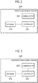
Fig. 2 is a diagram illustrating apower management server 200 according to the embodiment. -
Fig. 3 is a diagram illustrating anequipment management server 400 according to the embodiment. -
Fig. 4 is a diagram illustrating a distributedpower supply system 600 according to the embodiment. -
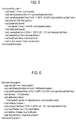
Fig. 5 is a diagram illustrating an example of a first message according to the embodiment. -
Fig. 6 is a diagram illustrating an example of a first message according to the embodiment. -
Fig. 7 is a diagram illustrating a distributed power supply control method according to the embodiment. -
Fig. 8 is a diagram illustrating the distributed power supply control method according to the embodiment. - A case where a power management server that controls a distributed power supply in order to maintain a power supply-demand balance of a power grid and an equipment management server that monitors the distributed power supply in order to perform maintenance on the distributed power supply belong to entities that are different from each other is conceivable.
- As a result of a diligent study, the inventors found that in such case, if a message transmitted from the equipment management server and a message transmitted from the power management server conflict with each other, such conflict of messages may hinder proper control of the distributed power supply.
- Therefore, the present disclosure is intended to solve the aforementioned problem and enables properly control of a distributed power supply.
- A distributed power supply system according to an embodiment includes a distributed power supply. The distributed power supply system includes: a communicator configured to receive a first message from a power management server configured to control the distributed power supply and receive a second message from an equipment management server configured to monitor the distributed power supply; and a controller configured to control the distributed power supply based on the first message and the second message. If the first message and the second message conflict with each other, the controller controls the distributed power supply based on the second message preferentially over the first message.
- An embodiment will be described below with reference to the drawings. Note that in the below descriptions of the drawings, identical or similar parts are provided with identical or similar reference numerals.
- In this regard, it should be born in mind that the drawings are schematic, and a ratio of each dimension is different from actual one. Therefore, each specific dimension needs to be decided in view of the following description. Of course, the drawings naturally includes portions having different dimensional relationships or ratios.
- A power system according to an embodiment will be described below.
- As illustrated in
Fig. 1 , apower system 100 includes apower management server 200,facilities 300, anequipment management server 400 and apredetermined server 500. InFig. 1 , as thefacilities 300,facilities 300Ato 300C are illustrated. - Each
facility 300 is connected to apower grid 110. Hereinafter, a flow of power from thepower grid 110 to thefacility 300 will be referred to as a power flow, and a flow of power from thefacility 300 to thepower grid 110 will be referred to as a reverse power flow. - The
power management server 200 is a server that controls distributed power supplies (for example, later-described distributed power supplies 310). Thepower management server 200 transmits a first message that provides an instruction on control of adistributed power supply 310 provided in afacility 300 to an EMS 330 provided in thefacility 300. For example, thepower management server 200 may transmit a power flow control message (for example, demand response (DR)) that demands control of a power flow or may transmit a reverse power flow control message that demands control of a reverse power flow. Furthermore, thepower management server 200 may transmit a power supply control message for controlling an operating state of a distributed power supply. A degree of control of a power flow or a reverse power flow may be expressed by an absolute value (for example, xx kW) or may be expressed by a relative value (for example, xx%). Alternatively, the degree of control of a power flow or a reverse power flow may be expressed in two or more levels. The degree of control of a power flow or a reverse power flow may be expressed by a power rate determined by a current power supply-demand balance (real time pricing (RTP)) or may be expressed by a power rate determined by a past power supply-demand balance (time of use (TOU)). - For example, the
power management server 200 is managed by power companies such as a power generation company, a power distribution company and a retail company. The first message is a message for the power companies to adjust a power supply-demand balance of thepower grid 110. - Each
facility 300 includes adistributed power supply 310,load equipment 320 and an EMS 330. - The
distributed power supply 310 may be a fuel cell apparatus that generates power using a fuel. The fuel cell apparatus is an apparatus that generates power using a fuel. For example, the fuel cell apparatus may be at least one of a solid oxide fuel cell (SOFC), a polymer electrolyte fuel cell (PEFC), a phosphoric acid fuel cell (PAFC) and a molten carbonate fuel cell (MCFC). Thedistributed power supply 310 may be an apparatus that generates power using at least one of natural energies such as sunlight, wind power, water power and ground heat. Thedistributed power supply 310 may be a power storage apparatus that performs power charge and power discharge. - The
load equipment 320 is equipment that consumes power. For example, theload equipment 320 is at least one of air-conditioning equipment, lighting equipment and audio visual (AV) equipment. - The EMS 330 is an apparatus (energy management system (EMS)) that manages power in the
facility 300. The EMS 330 corresponds to a control apparatus. The EMS 330 may control operating states of thedistributed power supply 310 and theload equipment 320. The EMS 330 is an example of a virtual end node (VEN). - The
equipment management server 400 is a server that monitors distributed power supplies (for example, the above-described distributed power supplies 310). Theequipment management server 400 transmits a second message for performing maintenance of thedistributed power supply 310 provided in afacility 300 to the EMS 330 provided in thefacility 300. For example, the maintenance includes, e.g., an inspection for inspecting a deterioration status of the facility, maintenance in which minor care is taken during an inspection, a repair for dealing with a defect of the facility and replacement of existing equipment with new equipment. Note that the maintenance may be performed during stoppage of the distributedpower supply 310 or may be performed during operation of the distributedpower supply 310. - For example, the
equipment management server 400 is managed by equipment suppliers such as a manufacturer, a distributor, and a maintenance provider of the distributed power supplies 310. - The
predetermined server 500 is a server that relays a first message and a second message. Thepredetermined server 500 may transmit a first message for afacility 300 managed by thepredetermined server 500, based on a first message for thefacility 300 managed by thepower management server 200. Thepredetermined server 500 may relay a second message transparently. - For example, the
predetermined server 500 is managed by a resource aggregator. The resource aggregator is a power company that provides power in a reverse power flow to, e.g., a power generation company, a power distribution company and a retail company, in a virtual power plant (VPP). The resource aggregator may be a power company that generates surplus power (negawatts) by reduction of power consumed by facilities managed by the resource aggregator. Such surplus power may be regarded as generated power. The resource aggregator may be a power company that absorbs extra power by means of an increase of power consumed by a facility managed by the resource aggregator (for example, an increase in amount of charge in a storage battery apparatus). - In the embodiment, communication between the
power management server 200 and thepredetermined server 500, communication between theequipment management server 400 and thepredetermined server 500 and communication between thepredetermined server 500 and theEMSs 330 may be performed according to a first protocol. On the other hand, communication between eachEMS 330 and the relevant distributedpower supply 310 and communication between eachEMS 330 and therelevant load equipment 320 may be performed according to a second protocol that is different from the first protocol. For example, for the first protocol, a protocol that complies with Open Automated Demand Response (ADR) 2.0 or a unique dedicated protocol can be used. For example, for the second protocol, a protocol that complies with ECHONET Lite, Smart Energy Profile (SEP) 2.0, KNX or a unique dedicated protocol can be used. The first protocol and the second protocol only need to be different from each other, and, for example, even if the first protocol and the second protocol are both unique dedicated protocols, the unique dedicated protocols only need to be protocols created according to different rules. - A power management server according to the embodiment will be described below. As illustrated in
Fig. 2 , thepower management server 200 includes adatabase 210, acommunicator 220 and acontroller 230. Thepower management server 200 is an example of a virtual top node (VTN). - The
database 210 includes a storage medium such as a non-volatile memory or/and a hard disk drive (HDD) and stores data relating to thefacilities 300 managed by thepower management server 200. Each of thefacilities 300 managed by thepower management server 200 may be afacility 300 that contracts with a power company. For example, the data relating to thefacilities 300 may be demand power supplied from thepower grid 110 to thefacilities 300. The data relating to thefacilities 300 may be at least one of, e.g., a type of the distributedpower supply 310 provided in eachfacility 300 and a specification of the distributedpower supply 310 provided in eachfacility 300. The specification may be, e.g., a rated generated power (W) and a maximum power output (W) of the distributedpower supply 310. - The
communicator 220 includes a communication module and performs communication with theEMSs 330 via thepredetermined server 500. As described above, thecommunicator 220 performs communication according to the first protocol. - The
controller 230 includes a control circuit including, e.g., a memory and a central processing unit (CPU) and controls respective components provided in thepower management server 200. For example, thecontroller 230 determines transmission of a first message from the perspective of the power supply-demand balance of thepower grid 110. The first message may be any of messages in (a1) to (a7) below or a message that is a combination of two or more of the messages. -
- (a1) A message that provides an instruction to increase or decrease an output of the distributed
power supply 310 in order to maintain the power supply-demand balance; - (a2) A message that provides an instruction to stop or start operation of the distributed
power supply 310 in order to maintain the power supply-demand balance; - (a3) A message that designates a time for starting stoppage of operation of the distributed
power supply 310 or a time for starting operation of the distributedpower supply 310 in order to maintain the power supply-demand balance; - (a4) A message that designates a time or a duration during which maintenance of the power supply-demand balance is necessary;
- (a5) A message that provides notification of an end of maintenance of the power supply-demand balance;
- (a6) A message that provides an instruction to resume operation of the distributed
power supply 310 along with an end of maintenance of the power supply-demand balance; and - (a7) A message that urges a return to a normal mode along with an end of maintenance of the power supply-demand balance.
- As described above, the first message may be at least one of a power flow control message, a reverse power flow control message and a power supply control message.
- An equipment management server according to the embodiment will be described below. As illustrated in
Fig. 3 , theequipment management server 400 includes adatabase 410, acommunicator 420 and acontroller 430. - The
database 410 includes a storage medium such as a non-volatile memory or/and an HDD and manages information relating to the plurality offacilities 300. - The
database 410 may store basic information of the equipment provided in each of the plurality offacilities 300. Thedatabase 410 stores, for example, a facility name, a facility ID, an equipment name, an equipment ID, an installation year, an age and a useful life in association with one another. The facility name is a name of thefacility 300 in which the relevant equipment is installed. The facility ID is an identifier that identifies thefacility 300. The equipment name is a name of the equipment. The equipment ID is an identifier that identifies the equipment. The installation year is a year in which the equipment was installed. The age is the number of years passed since the installation of the equipment. The useful life, which is determined by, e.g., a manufacturer of the equipment, is information indicating a duration during which the equipment can properly be used since the installation of the equipment. - For the
respective facilities 300, thedatabase 410 may store maintenance information of the equipment provided in each of the plurality offacilities 300. Thedatabase 410 stores, for example, a facility name, an equipment name, a maintenance date, a maintenance overview and maintenance details in association with one another. Thedatabase 410 may store a facility ID and an equipment ID in association with these information pieces. The facility name and the equipment name are as described above. The maintenance date is a date on which maintenance was performed. The maintenance overview is information indicating an overview of the maintenance, and the maintenance details are information pieces indicating details of the maintenance. Maintenance information according to the embodiment only needs to include at least a maintenance term (schedule) for performing maintenance of equipment in the future. The maintenance information may include a maintenance term in which maintenance of the equipment was performed in the past. - The
communicator 420 includes a communication module and performs communication with theEMSs 330 via thepredetermined server 500. As described above, thecommunicator 420 performs communication according to the first protocol. - The
controller 430 includes a control circuit including, e.g., a memory and a CPU and controls respective components provided in theequipment management server 400. For example, thecontroller 430 determines transmission of a second message from the perspective of maintenance of a distributedpower supply 310. The second message may be any of messages in (b1) to (b6) below or a message that is a combination of two or more of the messages. -
- (b1) A message that provides an instruction to stop operation of the distributed
power supply 310 in order to start maintenance; - (b2) A message that designates a time for starting stoppage of operation of the distributed
power supply 310 in order to start maintenance; - (b3) A message that designates a time or a duration necessary for maintenance of the distributed
power supply 310; - (b4) A message that provides notification of an end of maintenance of the distributed
power supply 310; - (b5) A message that provides an instruction to resume operation of the distributed
power supply 310 along with an end of maintenance of the distributedpower supply 310; and - (b6) A message that urges a return to a normal mode along with an end of maintenance of the distributed
power supply 310. - A distributed power supply system according to the embodiment will be described below. As illustrated in
Fig. 4 , a distributedpower supply system 600 includes acommunicator 610 and acontroller 620. The distributedpower supply system 600 only needs to be a system including the distributed power supplies 310. For example, the distributedpower supply system 600 includes the distributedpower supplies 310 and theEMSs 330. The distributedpower supply system 600 may include the distributedpower supplies 310 without including theEMSs 330. - The
communicator 610 includes a communication module and performs communication with thepower management server 200 and theequipment management server 400 via thepredetermined server 500. In other words, thecommunicator 610 receives a first message from thepower management server 200 and receives a second message from theequipment management server 400. - The
controller 620 includes a control circuit including, e.g., a memory and a CPU and controls respective components provided in the distributedpower supply system 600. For example, thecontroller 620 controls each distributedpower supply 310 based on a first message and a second message. - In the embodiment, if a first message and a second message conflict with each other, the
controller 620 controls the relevant distributedpower supply 310 based on the second message preferentially over the first message. As a conflict between a first message and a second message, a case of controlling a distributedpower supply 310 based on a second message for a time slot in which the distributedpower supply 310 is controlled based on a first message is conceivable. For example, a case of an instruction to stop a distributedpower supply 310 being provided based on a second message in a time slot in which an instruction to increase or decrease an output of the distributedpower supply 310 has been provided based on a first message is conceivable. Alternatively, a case of controlling a distributedpower supply 310 based on a first message for a time slot in which the distributedpower supply 310 is controlled based on a second message is conceivable. For example, a case of an instruction to increase or decrease an output of a distributedpower supply 310 being provided based on a first message in a time slot in which an instruction to stop the distributedpower supply 310 has been provided based on a second message is conceivable. In other words, a conflict between a first message and a second message includes a situation in which control performed based on a first message and control performed based on a second message cannot be implemented simultaneously or a problem can occur as a result of both being implemented simultaneously. - Here, a case where a communication protocol for a first message and a communication protocol for a second message are the same will be considered. In the embodiment, since a first message and a second message are transmitted from the
predetermined server 500 to the distributedpower supply system 600, if communication protocols for the first message and the second message are the same, thecontroller 620 may fail to distinguish between the first message and the second message. Therefore, in the embodiment, a first message is configured in such a manner as to be identifiable as a message transmitted from thepower management server 200 or a second message is configured in such a manner as to be identifiable as a message transmitted from theequipment management server 400. - For example, a case where communication protocols for a first message and a second message comply with Open ADR 2.0 will be considered.
- Firstly, as illustrated in
Figs. 5 and 6 , a first message and a second message each include an information element indicating a priority order (here, <ns2: priority>). Thecontroller 620 determines whether a message received by thecommunicator 610 is one transmitted from thepower management server 200 or one transmitted from theequipment management server 400, based on the priority orders. More specifically, as illustrated inFig. 5 , the priority order of the first message is "100", and as illustrated inFig. 6 , the priority order of the second message is "1". In such case, the predetermined value "1" may be determined as a priority order used only for the second message. In other words, a priority order having a value other than the predetermined value "1" may be set based on the priority order of the first message. - Secondly, as illustrated in
Figs. 5 and 6 , the first message and the second message may each include an information element usable for identification of control of a distributed power supply 310 (here, <ns4: marketContext>). Thecontroller 620 determines whether a message received by thecommunicator 610 is one transmitted from thepower management server 200 or one transmitted from theequipment management server 400, based on a marketContext priority order. More specifically, as illustrated inFig. 5 , the marketContext in the first message is "DR" and as illustrated inFig. 6 , the marketContext in the second message is "Maintenance". In such case, it should be noted that the predetermined value "Maintenance" is a newly defined value. - Furthermore, the
controller 620 may refuse acceptance of a first message until starting of a distributedpower supply 310 is performed after reception of a second message that provides an instruction to stop the distributedpower supply 310. In such case, if acceptance of the first message is refused, thecommunicator 610 may transmit a notification message indicating that control based on the first message is not performed to thepower management server 200. - A distributed power supply control method according to the embodiment will be described below. In
Figs. 7 and8 , illustration of thepredetermined server 500 is omitted. - Firstly, a case of controlling a distributed
power supply 310 based on a second message for a time slot in which the distributedpower supply 310 is controlled based on a first message will be considered. - In step S10, the
power management server 200 transmits a first message to the distributedpower supply system 600. - In step S11, the
equipment management server 400 transmits a second message to the distributedpower supply system 600. - In step S12, the distributed
power supply system 600 determines whether or not the first message and the second message conflict with each other. The distributedpower supply system 600 may make the determination based on the priority orders or may make the determination based on marketContext. Here, the description will be continued with regard to the case where the first message and the second message conflict with each other. - In step S13, the distributed
power supply system 600 controls the relevant distributedpower supply 310 based on the second message. If control of the distributedpower supply 310 based on the first message has been started, the distributedpower supply system 600 cancels the control based on the first message. Also, the distributedpower supply system 600 may transmit a notification message indicating that control based on the first message is not performed to thepower management server 200. Such processing may be omitted where the control based on the first message is the same as the control based on the second message. On the other hand, if control of the distributedpower supply 310 based on the first message has not been started, the distributedpower supply system 600 performs control based on the second message without performing control based on the first message. - Secondly, a case of controlling a distributed
power supply 310 based on a first message for a time slot in which the distributedpower supply 310 is controlled based on a second message will be considered. - In step S20, the
equipment management server 400 transmits a second message to the distributedpower supply system 600. - In step S21, the
power management server 200 transmits a first message to the distributedpower supply system 600. - In step S22, the distributed
power supply system 600 refuses acceptance of the first message. For example, if the second message is a message that provides an instruction to stop the relevant distributedpower supply 310, the distributedpower supply system 600 may refuse acceptance of the first message until starting of the distributedpower supply 310 is performed. Here, starting of the distributedpower supply 310 may manually be performed by a maintenance provider or may be performed in response to reception of a second message that provides an instruction to resume operation of the distributedpower supply 310. - In step S23, the distributed
power supply system 600 transmits a notification message indicating that control based on the first message is not performed to thepower management server 200. - In step S24, the distributed
power supply system 600 controls the distributedpower supply 310 based on the second message. - In the embodiment, if a first message and a second message conflict with each other, the distributed
power supply system 600 controls the relevant distributedpower supply 310 based on the second message preferentially over the first message. Such configuration enables properly resolving the conflict between the first message and the second message and thus enables properly controlling the distributedpower supply 310. - Here, the embodiment solves a conflict between a first message and a second message based on new knowledge that maintenance should be prioritized over a power supply-demand balance. The embodiment enables, where a maintenance provider visits an installation site of a distributed
power supply 310 on the premise that the distributedpower supply 310 is controlled based on a second message, curbing breakup of such premise. For example, if a fuel cell apparatus that takes a long time to transition from a power generation state to a stopped state is assumed, it is possible to avoid a problem that when a maintenance provider visits an installation site of the fuel cell apparatus, the fuel cell apparatus is not stopped as scheduled. - Although the present disclosure has been described by the above-described embodiment, it should not be understood that the descriptions and the drawings that form a part of this disclosure limit the present invention. Various alternative embodiments, examples, and operation techniques will be apparent to those skilled in the art from this disclosure.
- In the embodiment, a first message and a second message are transmitted to an
EMS 330. However, the embodiment is not limited to this case. A first message and a second message may directly be transmitted to a distributedpower supply 310. In such case, therelevant EMS 330 may function as a router or noEMS 330 may be provided. - In the embodiment, the
predetermined server 500 is provided. However, the embodiment is not limited to this case. Nopredetermined server 500 may be provided. In such case, thepower management server 200 may relay a second message or theequipment management server 400 may relay a first message. Alternatively, thepower management server 200 may transmit a first message directly to the distributedpower supply system 600 and theequipment management server 400 may transmit a second message directly to the distributedpower supply system 600. - In the embodiment, a case where a communication protocol for a first message and a communication protocol for a second message are the same has been described; however, the embodiment is not limited to this case. A communication protocol for a first message and a communication protocol for a second message may be different from each other.
- In the embodiment, the
database 210 is provided in thepower management server 200; however, the embodiment is not limited to this case. For example, thedatabase 210 may be provided in a server connected to thepower management server 200 via a network. - In the embodiment, the
database 410 is provided in theequipment management server 400, but the embodiment is not limited to this case. For example, thedatabase 410 may be provided in a server connected to theequipment management server 400 via a network. - In the embodiment, a case where the first protocol is a protocol that complies with Open ADR 2.0 and the second protocol is a protocol that complies with ECHONET Lite has been indicated as an example. However, the embodiment is not limited to this case. The first protocol only needs to be a protocol standardized as a protocol used for communication between the
power management server 200 and thepredetermined server 500, communication between theequipment management server 400 and thepredetermined server 500 and communication between thepredetermined server 500 and theEMSs 330. The second protocol only needs to be a protocol standardized as a protocol used in thefacilities 300. - In the embodiment, the distributed
power supply system 600 is described as, if a first message and a second message including a message that provides an instruction to stop operation of a distributedpower supply 310 in order to start maintenance conflict with each other, controlling the distributedpower supply 310 based on the second message preferentially over the first message; however, the embodiment is not limited to this case. If the second message includes a message that provides an instruction to resume operation of the distributedpower supply 310 along with an end of maintenance of the distributedpower supply 310, the first message and the second message may be regarded as not conflicting with each other. In this case, since maintenance of the distributedpower supply 310 has already finished, the distributedpower supply system 600 may control the distributedpower supply 310 in such a manner as to prioritize stoppage of operation of the distributedpower supply 310 for maintenance of a power supply-demand balance over resumption of operation of the distributedpower supply 310 along with an end of maintenance of the distributedpower supply 310. Also, in this case, the distributedpower supply system 600 may transmit a notification message indicating that control based on the second message is not performed to theequipment management server 400. - The present application claims priory to Japanese Patent Application No.
2018-140935 (filed on July 27, 2018
Claims (20)
- A distributed power supply system including a distributed power supply, the distributed power supply system comprising:a communicator configured toreceive a first message from a power management server configured to control the distributed power supply, andreceive a second message from an equipment management server configured to monitor the distributed power supply; anda controller configured to control the distributed power supply based on the first message and the second message,wherein if the first message and the second message conflict with each other, the controller controls the distributed power supply based on the second message preferentially over the first message.
- The distributed power supply system according to claim 1, wherein:a communication protocol for the first message is the same as a communication protocol for the second message; andthe first message is configured to be identifiable as a message transmitted from the power management server, or the second message is configured to be identifiable as a message transmitted from the equipment management server.
- The distributed power supply system according to claim 2, wherein:each of the first message and the second message includes an information element indicating a priority order; andthe controller determines whether a message received by the communicator is one transmitted from the power management server or one transmitted from the equipment management server, based on the priority orders.
- The distributed power supply system according to any one of claims 1 to 3, wherein after reception of the second message that provides an instruction to stop the distributed power supply, the controller refuses acceptance of the first message until starting of the distributed power supply is performed.
- The distributed power supply system according to claim 4, wherein if acceptance of the first message is refused, the communicator transmits, to the power management server, a message indicating that control based on the first message is not performed.
- The distributed power supply system according to any one of claims 1 to 5, wherein the communicator receives the first message and the second message via a predetermined server connected to the power management server and the equipment management server.
- The distributed power supply system according to any one of claims 1 to 6, wherein the distributed power supply is a fuel cell system.
- The distributed power supply system according to any one of claims 1 to 7, wherein the first message includes a message that provides an instruction to increase or decrease an output of the distributed power supply in order to maintain a power supply-demand balance.
- The distributed power supply system according to any one of claims 1 to 7, wherein the first message includes a message that provides an instruction to stop or start operation of the distributed power supply in order to maintain a power supply-demand balance.
- The distributed power supply system according to any one of claims 1 to 7, wherein the first message includes a message that designates a time for starting stoppage of operation of the distributed power supply or a time for starting operation of the distributed power supply in order to maintain a power supply-demand balance.
- The distributed power supply system according to any one of claims 1 to 7, wherein the first message includes a message that designates a time or a duration during which maintenance of a power supply-demand balance is necessary.
- The distributed power supply system according to any one of claims 1 to 7, wherein the first message includes a message that provides notification of an end of maintenance of a power supply-demand balance.
- The distributed power supply system according to any one of claims 1 to 12, wherein the second message include a message that provides an instruction to stop operation of the distributed power supply in order to start maintenance of the distributed power supply.
- The distributed power supply system according to any one of claims 1 to 12, wherein the second message includes a message that designates a time for starting stoppage of operation of the distributed power supply in order to start maintenance of the distributed power supply.
- The distributed power supply system according to any one of claims 1 to 12, wherein the second message includes a message that designates a time or a duration necessary for maintenance of the distributed power supply.
- The distributed power supply system according to any one of claims 1 to 12, wherein the second message includes a message that provides notification of an end of maintenance of the distributed power supply.
- The distributed power supply system according to any one of claims 1 to 12, wherein the second message includes a message that provides an instruction to resume operation of the distributed power supply along with an end of maintenance of the distributed power supply.
- The distributed power supply system according to any one of claims 1 to 12, wherein the second message includes a message that urges a return to a normal mode along with an end of maintenance of the distributed power supply.
- A control apparatus comprising:a communicator configured toreceive a first message from a power management server configured to control a distributed power supply, andreceive a second message from an equipment management server configured to monitor the distributed power supply; anda controller configured to control the distributed power supply based on the first message and the second message,wherein if the first message and the second message conflict with each other, the controller controls the distributed power supply based on the second message preferentially over the first message.
- A distributed power supply control method comprising:receiving a first message from a power management server configured to control a distributed power supply;receiving a second message from an equipment management server configured to monitor the distributed power supply; andcontrolling the distributed power supply based on the first message and the second message,wherein the controlling the distributed power supply includes controlling the distributed power supply based on the second message preferentially over the first message if the first message and the second message conflict with each other.
Applications Claiming Priority (2)
| Application Number | Priority Date | Filing Date | Title |
|---|---|---|---|
| JP2018140935 | 2018-07-27 | ||
| PCT/JP2019/028442 WO2020022210A1 (en) | 2018-07-27 | 2019-07-19 | Distributed power supply system, control device, and distributed power supply control method |
Publications (2)
| Publication Number | Publication Date |
|---|---|
| EP3832846A1 true EP3832846A1 (en) | 2021-06-09 |
| EP3832846A4 EP3832846A4 (en) | 2022-04-06 |
Family
ID=69182030
Family Applications (1)
| Application Number | Title | Priority Date | Filing Date |
|---|---|---|---|
| EP19840809.8A Pending EP3832846A4 (en) | 2018-07-27 | 2019-07-19 | Distributed power supply system, control device, and distributed power supply control method |
Country Status (5)
| Country | Link |
|---|---|
| US (1) | US11611216B2 (en) |
| EP (1) | EP3832846A4 (en) |
| JP (1) | JP7004819B2 (en) |
| CN (1) | CN112544027B (en) |
| WO (1) | WO2020022210A1 (en) |
Families Citing this family (3)
| Publication number | Priority date | Publication date | Assignee | Title |
|---|---|---|---|---|
| FR3102019B1 (en) * | 2019-10-11 | 2021-10-22 | Nw Joules | AUTOMOTIVE VEHICLE QUICK CHARGE DEVICE |
| EP4191813A4 (en) * | 2020-07-29 | 2024-11-13 | Kyocera Corporation | Electric power management server, and electric power management method |
| JP2023177798A (en) * | 2022-06-03 | 2023-12-14 | 京セラ株式会社 | Management device and management method |
Family Cites Families (24)
| Publication number | Priority date | Publication date | Assignee | Title |
|---|---|---|---|---|
| JP4069944B2 (en) | 2001-03-29 | 2008-04-02 | 株式会社日立製作所 | Power plant control method, operation command method |
| US7436321B2 (en) * | 2002-12-10 | 2008-10-14 | Current Technologies, Llc | Power line communication system with automated meter reading |
| US20050034023A1 (en) * | 2002-12-16 | 2005-02-10 | Maturana Francisco P. | Energy management system |
| JP2005182399A (en) | 2003-12-18 | 2005-07-07 | Silis:Kk | Store chart management system |
| US7715951B2 (en) * | 2007-08-28 | 2010-05-11 | Consert, Inc. | System and method for managing consumption of power supplied by an electric utility |
| CN102801156B (en) * | 2011-05-25 | 2016-01-13 | 株式会社日立制作所 | System mode arithmetic unit method and system, system control device and method, distribution system Power flow simulation device and method |
| US9099868B2 (en) * | 2011-05-31 | 2015-08-04 | Cisco Technology, Inc. | Control federation for utility grids |
| JP5822626B2 (en) * | 2011-10-03 | 2015-11-24 | 生活協同組合コープさっぽろ | Power management server and power management processing program |
| KR20130037610A (en) * | 2011-10-06 | 2013-04-16 | 삼성전자주식회사 | Apparatus and method for preventing collision between two commands in smart grid network |
| US20130234523A1 (en) * | 2012-03-06 | 2013-09-12 | First Solar, Inc | Method and apparatus providing point of interconnection control for power plants |
| US9563215B2 (en) * | 2012-07-14 | 2017-02-07 | Causam Energy, Inc. | Method and apparatus for actively managing electric power supply for an electric power grid |
| US8983669B2 (en) * | 2012-07-31 | 2015-03-17 | Causam Energy, Inc. | System, method, and data packets for messaging for electric power grid elements over a secure internet protocol network |
| KR101949561B1 (en) | 2012-10-12 | 2019-02-18 | 코닝 인코포레이티드 | Articles having retained strength |
| US9703309B2 (en) * | 2013-12-27 | 2017-07-11 | Abb Schweiz Ag | Method and apparatus for distributed overriding automatic reclosing of fault interrupting devices |
| WO2015192110A1 (en) * | 2014-06-12 | 2015-12-17 | Steven Goldsmith | Agent-based microgrid architecture for generation following protocols |
| JP6587336B2 (en) * | 2015-05-08 | 2019-10-09 | 秀一 石原田 | Renewable energy storage system |
| JP6696778B2 (en) * | 2016-01-21 | 2020-05-20 | 京セラ株式会社 | Management server and management method |
| US11327475B2 (en) * | 2016-05-09 | 2022-05-10 | Strong Force Iot Portfolio 2016, Llc | Methods and systems for intelligent collection and analysis of vehicle data |
| JP6732182B2 (en) * | 2016-07-26 | 2020-07-29 | 京セラ株式会社 | Power management server, power management method, and power management system |
| EP3509184A4 (en) | 2016-08-31 | 2020-03-04 | Kyocera Corporation | ENERGY MANAGEMENT METHOD, ENERGY MANAGEMENT SERVER, LOCAL CONTROL APPARATUS AND ENERGY MANAGEMENT SYSTEM |
| US10483754B2 (en) * | 2017-05-01 | 2019-11-19 | Abb Schweiz Ag | Fault detection and location in nested microgrids |
| US11291510B2 (en) * | 2017-10-30 | 2022-04-05 | Cilag Gmbh International | Method of hub communication with surgical instrument systems |
| JP6928670B2 (en) * | 2017-11-29 | 2021-09-01 | 京セラ株式会社 | Power management server and power management method |
| US11336111B2 (en) * | 2018-06-08 | 2022-05-17 | Powin, Llc | Microgrid power system |
-
2019
- 2019-07-19 JP JP2020532354A patent/JP7004819B2/en active Active
- 2019-07-19 CN CN201980049911.4A patent/CN112544027B/en active Active
- 2019-07-19 WO PCT/JP2019/028442 patent/WO2020022210A1/en not_active Ceased
- 2019-07-19 US US17/263,547 patent/US11611216B2/en active Active
- 2019-07-19 EP EP19840809.8A patent/EP3832846A4/en active Pending
Also Published As
| Publication number | Publication date |
|---|---|
| CN112544027A (en) | 2021-03-23 |
| US11611216B2 (en) | 2023-03-21 |
| CN112544027B (en) | 2024-02-13 |
| WO2020022210A1 (en) | 2020-01-30 |
| US20210249866A1 (en) | 2021-08-12 |
| JP7004819B2 (en) | 2022-01-21 |
| JPWO2020022210A1 (en) | 2021-08-02 |
| EP3832846A4 (en) | 2022-04-06 |
Similar Documents
| Publication | Publication Date | Title |
|---|---|---|
| US20190199131A1 (en) | Power management method, power management server, local control apparatus, and power management system | |
| JP7014903B2 (en) | Device management server, device management system and device management method | |
| US11611216B2 (en) | Distributed power supply system, control apparatus and distributed power supply control method | |
| JPWO2020004053A1 (en) | Management server, management system, and management method | |
| EP3509185A1 (en) | Electric power management method, electric power management server, local control device, and electric power management system | |
| EP3343729A1 (en) | Communication device, management server, and communication method | |
| US12155213B2 (en) | Energy management apparatus, energy storage apparatus, and energy management method | |
| US12000897B2 (en) | Power management apparatus, power management system and power management method | |
| WO2019044574A1 (en) | Power supply management method and power supply management device | |
| EP3605438B1 (en) | Energy management method, energy management device, and energy management system | |
| JP6732205B2 (en) | Power management method, power management server, local control device, and power management system | |
| JP2023005861A (en) | Power management device, power management system, and power management method | |
| JP7341009B2 (en) | Power management system and power management method | |
| JP7316433B2 (en) | Power management device, power storage device, and power management method | |
| JP7386915B2 (en) | Power management server and power management method | |
| JP7590262B2 (en) | Power management device, power management system, and power management method | |
| JP2022050576A (en) | Power management device, power storage device and power management method |
Legal Events
| Date | Code | Title | Description |
|---|---|---|---|
| STAA | Information on the status of an ep patent application or granted ep patent |
Free format text: STATUS: THE INTERNATIONAL PUBLICATION HAS BEEN MADE |
|
| PUAI | Public reference made under article 153(3) epc to a published international application that has entered the european phase |
Free format text: ORIGINAL CODE: 0009012 |
|
| STAA | Information on the status of an ep patent application or granted ep patent |
Free format text: STATUS: REQUEST FOR EXAMINATION WAS MADE |
|
| 17P | Request for examination filed |
Effective date: 20210127 |
|
| AK | Designated contracting states |
Kind code of ref document: A1 Designated state(s): AL AT BE BG CH CY CZ DE DK EE ES FI FR GB GR HR HU IE IS IT LI LT LU LV MC MK MT NL NO PL PT RO RS SE SI SK SM TR |
|
| DAV | Request for validation of the european patent (deleted) | ||
| DAX | Request for extension of the european patent (deleted) | ||
| A4 | Supplementary search report drawn up and despatched |
Effective date: 20220303 |
|
| RIC1 | Information provided on ipc code assigned before grant |
Ipc: H02J 3/38 20060101ALI20220225BHEP Ipc: H02J 13/00 20060101AFI20220225BHEP |
|
| STAA | Information on the status of an ep patent application or granted ep patent |
Free format text: STATUS: EXAMINATION IS IN PROGRESS |
|
| 17Q | First examination report despatched |
Effective date: 20230309 |
|
| P01 | Opt-out of the competence of the unified patent court (upc) registered |
Effective date: 20230505 |
|
| STAA | Information on the status of an ep patent application or granted ep patent |
Free format text: STATUS: THE APPLICATION IS DEEMED TO BE WITHDRAWN |