EP3832697A1 - Atmospheric-pressure plasma generator - Google Patents
Atmospheric-pressure plasma generator Download PDFInfo
- Publication number
- EP3832697A1 EP3832697A1 EP18928948.1A EP18928948A EP3832697A1 EP 3832697 A1 EP3832697 A1 EP 3832697A1 EP 18928948 A EP18928948 A EP 18928948A EP 3832697 A1 EP3832697 A1 EP 3832697A1
- Authority
- EP
- European Patent Office
- Prior art keywords
- gas
- plasma
- temperature
- nox
- atmospheric pressure
- Prior art date
- Legal status (The legal status is an assumption and is not a legal conclusion. Google has not performed a legal analysis and makes no representation as to the accuracy of the status listed.)
- Granted
Links
Images


Classifications
-
- H—ELECTRICITY
- H01—ELECTRIC ELEMENTS
- H01J—ELECTRIC DISCHARGE TUBES OR DISCHARGE LAMPS
- H01J37/00—Discharge tubes with provision for introducing objects or material to be exposed to the discharge, e.g. for the purpose of examination or processing thereof
- H01J37/32—Gas-filled discharge tubes
- H01J37/32431—Constructional details of the reactor
- H01J37/3244—Gas supply means
-
- H—ELECTRICITY
- H01—ELECTRIC ELEMENTS
- H01J—ELECTRIC DISCHARGE TUBES OR DISCHARGE LAMPS
- H01J37/00—Discharge tubes with provision for introducing objects or material to be exposed to the discharge, e.g. for the purpose of examination or processing thereof
- H01J37/32—Gas-filled discharge tubes
- H01J37/32431—Constructional details of the reactor
- H01J37/32798—Further details of plasma apparatus not provided for in groups H01J37/3244 - H01J37/32788; special provisions for cleaning or maintenance of the apparatus
- H01J37/32816—Pressure
- H01J37/32825—Working under atmospheric pressure or higher
Definitions
- the present invention relates to an atmospheric pressure plasma gas generator.
- the temperature control has been carried out in the plasma treatment because the processing quality is affected by the temperature conditions.
- a temperature sensor and a heater are disposed in an interior of a sample table on which a wafer, which is to be etched through a plasma treatment within a vacuum container, is placed and are controlled so as to realize a predetermined temperature.
- Patent Literature 1 JP-A-2016-213359
- NOx is generated in an atmospheric-pressure plasma device in the case that a high-temperature plasma gas is generated under an environment in which oxygen and nitrogen exist. Since NOx is harmful to the environment or the like and then constitutes a target substance whose use is restricted by the relevant law and regulations, it is necessary to suppress the generation of NOx.
- the present patent application has been made in view of the problem described above, and an object there of is to provide an atmospheric pressure plasma gas generator configured to suppress the generation of NOx.
- an atmospheric pressure plasma generator including a pair of electrodes for generating a plasma through discharge, a reaction chamber incorporating the pair of electrodes and having an inlet port through which a process gas flows in and an outlet port through which a plasma gas generated as a result of the process gas being plasmatized by the pair of electrodes flows out, and a control device for controlling a temperature of the plasma gas which flows out from the outlet port so that a generation amount of NOx becomes a threshold or smaller.
- the atmospheric pressure plasma gas generator can be provided which can suppress the generation of NOx.
- atmospheric pressure plasma generator 10 includes plasma head 11, main body section 17, power cable 40, and gas pipe 80 and the like.
- Main body section 17 includes process gas supply device 77 and cooling gas supply device 102.
- power is transferred from main body section 17 to plasma head 11 via power cable 40, a process gas is supplied to plasma head 11 through gas pipe 80, and a plasma gas is irradiated from plasma head 11.
- the process gas refers to a gas in which an active gas such as oxygen and an inert gas such as nitrogen are mixed together at an arbitrary ratio
- the plasma gas refers to an oxygen plasma gas.
- Plasma head 11 is attached to a distal end of robot arm 141 of industrial robot 140.
- Robot arm 141 is an articulated robot in which two arm sections 145, 145 are coupled together in one direction.
- Industrial robot 140 drives robot arm 141 to execute an operation of irradiating a plasma gas on to workpiece W supported on work table 5.
- plasma head 11 has plasma gas ejection device 12 and heating gas supply device 14.
- a width direction of plasma head 11 refers to an X-direction
- a depth direction of atmospheric pressure plasma generator 10 refers to a Y-direction
- a direction at right angles to the X direction and the Y-direction, that is, an up-down direction refers to a Z direction.
- Plasma gas ejection device 12 is configured of upper housing 19, lower housing 20, lower cover 22, pair of electrodes 24, 26 ( Fig. 3 ), and pair of heatsinks 27, 28.
- Upper housing 19 and lower housing 20 are coupled together via rubber seal member 29 in such a state that upper housing 19 is placed on lower housing 20. Then, upper housing 19 and lower housing 20, which are coupled together, are held by pair of heatsinks 27, 28 therebetween on both side faces thereof which are oriented in the X-direction.
- a plasma gas is generated in reaction chamber 38 defined in an interior of lower housing 20, and the plasma gas so generated is ejected downwards from a lower face of lower cover 22.
- Heatsinks 27, 28 have a function of cooling upper housing 19, lower housing 20, and the like.
- a flow path reaching from supply port 96 to exhaust port 98 is formed in an interior of each of heatsinks 27, 28.
- a cooling gas which is air at about a room temperature, is supplied from cooling gas supply device 102 (refer to Fig. 17) to supply port 96 by way of supply pipe 100. The cooling gas is warmed up through heat exchange and is then let out from exhaust port 98.
- Heating gas supply device 14 has gas pipe 110, heater 112, and coupling block 114.
- Gas pipe 110 is connected to the flow paths defined in the interiors of heatsinks 27, 28 for the cooling gas to flow therethrough. Specifically speaking, gas pipe 110 is connected to exhaust ports 98 of pair of heatsinks 27, 28 by way of exhaust pipe 116 at an upper end portion thereof. Exhaust pipe 116 is bifurcated at a first end portion, and end portions of resulting bifurcated exhaust pipes 16 are coupled to corresponding exhaust ports 98 of pair of heatsinks 27, 28. On the other hand, exhaust pipe 116 is not bifurcated at a second end portion and is connected to an upper end of gas pipe 110.
- Heater 112 having a substantially cylindrical shape, is disposed around an outer peripheral surface of gas pipe 110, so that gas pipe 110 is heated by heater 112. As a result, the gas supplied from heatsinks 27, 28 into gas pipe 110 is heated.
- Lower housing 20 includes main housing 30, heat dissipation plate 31, earth plate 32, coupling block 34, and nozzle block 36.
- Main housing 30 has a block-like shape in general, and reaction chamber 38 is formed in an interior of main housing 30.
- Reaction chamber 38 has an inlet port (not shown) through which a process gas flows in and outlet port 39 through which a plasma gas flows out.
- Earth plate 32 functions as a lightning rod and is fixed to a lower face of main housing 30.
- Coupling block 34 is fixed to a lower face of earth plate 32, and nozzle block 36 is fixed to a lower face of coupling block 34.
- Heat dissipation plate 31 is disposed on a side face of main housing 30. Heat dissipation plate 31 has multiple fins (not shown), through which heat of main housing 30 is dissipated.
- Gas flow path 50 is formed in main housing 30, earth plate 32, coupling block 34, and nozzle block 36. Gas flow path 50 communicates with outlet port 39 of reaction chamber 38 at a first end and opens to a lower face of nozzle block 36 at a second end thereof. Opening of gas flow path 50 in nozzle block 36 constitutes outlet port 51.
- Coupling block 114 is coupled to a lower end of gas pipe 110 and is fixed to a side face of lower cover 22 which faces heating gas supply device 14 in the Y-direction.
- Communication path 120 is formed in coupling block 114, and communication path 120 opens to an upper face of coupling block 114 at a first end portion, and communication path 120 opens to a side face of coupling block 114 which faces plasma gas ejection device 12 in the Y-direction at a second end portion thereof. Then, communication path 120 communicates with the lower end of gas pipe 110 at the first end portion, and communication path 120 communicates with through hole 72 in lower cover 22 at the second end portion thereof. As a result, a gas heated in gas pipe 110 is supplied into lower cover 22.
- control device 16 is connected with process gas supply device 77 and cooling gas supply device 102 in such a manner as to communicate with each other, so that the individual sections are controlled by control device 16.
- Control device 16 has controller 130, which is configured mainly of a computer, and drive circuits 132 to 134.
- Drive circuit 132 constitutes a circuit for controlling power to be supplied to electrodes 24, 26.
- Drive circuit 133 constitutes a circuit for controlling flow rates of gases supplied by process gas supply device 77 and cooling gas supply device 102.
- Drive circuit 134 constitutes a circuit for controlling power supplied to heater 112.
- NOx sensor 151 and temperature sensor 152 are disposed near outlet port 51. A signal indicating a concentration of NOx, which is detected by NOx sensor 151, is output to controller 130.
- a signal indicating a temperature, which is detected by temperature sensor 152, is output to controller 130.
- plasma gas ejection device 12 is configured as described above, and in plasma gas ejection device 12, a process gas is plasmatized in the interior of reaction chamber 38, which turns out ejecting plasma gas from a lower end of nozzle block 36.
- a process gas is supplied to the interior of reaction chamber 38 by process gas supply device 77.
- process gas supply device 77 As this occurs, in reaction chamber 38, a voltage is applied to pair of electrodes 24, 26, which are incorporated in reaction chamber 38, and a current flows between pair of electrodes 24, 26.
- a discharge is generated between pair of electrodes 24, 26, whereby the process gas is plasmatized by the discharge, and resulting plasma gas is ejected.
- an ejection of a plasma gas may be referred to as a plasma irradiation from time to time.
- applying a voltage to electrodes 24, 26 under plasmatizing increases a temperature of reaction chamber 38.
- a cooling gas is supplied into the flow paths in heatsinks 27, 28 by cooling gas supply device 102, whereby reaction chamber 38 is cooled through heat exchange.
- the cooling gas that flows through the flow paths in heatsinks 27, 28 and is then warmed up through the heat exchange is supplied into gas pipe 110 and is then heated by heater 112.
- the cooling gas so heated is then supplied into an interior of lower cover 22 and is then ejected against the plasma gas from through hole 70 in lower cover 22.
- through hole 70 is situated in the vicinity of nozzle block 36 and is disposed in the flow path of the plasma gas ejected from the lower end of nozzle block 36. Then, the plasma gas is ejected from through hole 70 in lower cover 22 together with the heated cooling gas. The plasma gas is heated by the heated cooling gas so ejected. Since heater 112 is controlled by control device 16, the temperature of the plasma gas is also controlled.
- oxygen plasma is generated in atmospheric pressure plasma generator 10. It is known that oxygen plasma is combined with oxygen to generate ozone. The inventors measured a concentration of NOx generated in atmospheric pressure plasma generator 10 this time.
- Fig. 5 is a graph showing concentrations of ozone (a solid line) and NOx (a broken line) with respect to source temperatures.
- a source temperature means a temperature in the vicinity, for example, of outlet port 51.
- a reaction between oxygen radical and nitrogen or a reaction between oxygen and nitrogen under a high-temperature condition can be considered as a NOx generation mechanism. As shown in Fig.
- control device 16 controls the temperature of a plasma gas so that an amount of generation of NOx becomes a threshold or smaller. Specifically speaking, control device 16 controls heater 112 based on a signal output from NOx sensor 151 so that the concentration of NOx becomes the threshold or smaller.
- the threshold needs to take a value based on, for example, a regulation value regulated by a relevant low or the like.
- reaction chamber 38 is cooled by cooling gas supply device 102, and the temperature of reaction chamber 38 falls down substantially to a temperature ranging from 300 to 400° C.
- the plasma gas is configured to be heated by the cooling gas which is heated by heater 112.
- the threshold is set, for example, at a value that slightly exceeds 0 [ppm], and heater 112 is configured to be controlled based on an output signal from NOx sensor 151 so that the concentration of NOx is not greater than the threshold.
- control device 16 causes heater 112 to stop heating. Further, control device 16 controls heater 112 based on a signal output from temperature sensor 152 so that the temperature becomes a target temperature. For example, in the case that an object to which plasma is irradiated is made of resin, the object is damaged in the event that a plasma gas is irradiated to the object with temperature higher than the temperature of a melting point of the resin.
- control device 16 switches on or off heater 12 to cause the cooling gas to heat so that the temperature of the plasma gas becomes its target temperature, the value of which is stored in advance in controller 130.
- the temperature of the plasma gas can be set to the target temperature while keeping the amount of generation of NOx at the threshold or smaller.
- electrodes 24, 26 represent an example of a pair of electrodes.
- Heater 112 represents an example of a heater
- heatsinks 27, 28 represent an example of a cooler.
- the vicinity of outlet port 51 represents an example of a flow path of a plasma gas.
- the cooling gas represents an example of a cooling heating gas
- coupling block 114 and lower cover 22 represent an example of a coupling section
- through hole 70 represents an example of an ejection port.
- Heating gas supply device 14 and lower cover 22 represent an example of a heating device.
- Control device 16 controls heater 112 based on a signal output from NOx sensor 151 so that the concentration of NOx becomes the threshold or smaller. As a result, the amount of generation of NOx can be limited to the threshold or smaller.
- control device 16 controls based on a signal output by temperature sensor 152 so that the temperature becomes the target temperature. As a result, the temperature of the plasma gas can be set to a temperature corresponding to an object to which the plasma gas is irradiated. Further, heating gas supply device 14 heats the cooling gas flowing through gas pipe 110 using heater 112. The plasma gas is heated by ejection of the heated cooling gas. As a result, the temperature of the plasma gas can be controlled by controlling heater 112.
- atmospheric pressure plasma generator 10 does not include temperature sensor 152 but includes NOx sensor 151.
- control device 16 controls heater 112 based on a signal output by NOx sensor 151 so that the concentration of NOx becomes the threshold or smaller. As a result, the amount of generation of NOx can be limited to the threshold or smaller.
- atmospheric pressure plasma generator 10 does not include NOx sensor 151 but includes temperature sensor 152 and an ozone sensor (not shown).
- control device 16 controls heater 112 based on a signal output by the ozone sensor so that a concentration of ozone becomes a predetermined value or greater.
- concentration of ozone becomes a predetermined value or greater.
- the concentration of NOx increases as the temperature increases, and when the temperature exceeds about 600°C, the concentration of NOx becomes greater than zero.
- the concentration of NOx can be estimated based on the concentration of ozone. Specifically speaking, correlation data between the concentration of ozone and the concentration of NOx is measured, and a value at which the concentration of NOx becomes the threshold or smaller is determined as a lower limit value for the concentration of ozone. Then, the lower limit value for the concentration of ozone so determined is stored in controller 130. Then, for irradiation of plasma, when a concentration of ozone indicated by an output signal from the ozone sensor becomes smaller than the lower limit value, control device 16 causes heater 112 to stop heating.
- control device 16 controls heater 112 based on a signal output from temperature sensor 152 so that the temperature becomes a target temperature.
- the temperature of the plasma gas can be adjusted to a temperature corresponding to an object to which the plasma gas is irradiated while maintaining the concentration of NOx to the threshold or smaller.
- control device 16 For irradiation of plasma, when a concentration of NOx indicated by an output signal from NOx sensor 151 becomes the threshold or greater, control device 16 causes heater 112 to stop heating, and when a centration of ozone indicated by an output signal from the ozone sensor becomes the lower limit value or smaller, control device 16 causes heater 112 to stop heating. As a result, an amount of generation of NOx can be set at the threshold or smaller in an ensured fashion.
- atmospheric pressure plasma generator 10 includes NOx sensor 151, temperature sensor 152, and an ozone sensor (not shown).
- control device 16 causes heater 112 to stop heating, and when a concentration of ozone indicated by an output signal from the ozone sensor becomes the lower limit value or smaller, control device 16 causes heater 112 to stop heating.
- control device 16 switches on or off heater 12 to cause the cooling gas to heat the cooling gas so that the temperature of the plasma gas becomes its target temperature, the value of which being stored in advance in controller 130.
- the temperature of the plasma gas can be set to the target temperature while keeping the amount of generation of NOx at the threshold or smaller in an ensured fashion.
- atmospheric pressure plasma generator 10 does not include NOx sensor 151 but includes temperature sensor 152.
- correlation data between the concentration of NOx and the temperature is measured, and a value at which the concentration of NOx becomes the threshold or smaller is determined as an upper limit value for the temperature. Then, the upper limit value of the temperature so determined is stored in controller 130.
- control device 16 causes heater 112 to stop heating. As a result, the amount of generation of NOx can be maintained at the threshold or smaller.
- atmospheric pressure plasma generator 10 does not include heater 112 but includes a cooling device (not shown).
- the embodiment described above adopts the configuration in which reaction chamber 38 is cooled by cooling gas supply device 102, and the plasma gas is heated by the cooling gas heated by heater 112. Since the temperature in reaction chamber 38 rises as a result of application of the voltage to electrodes 24, 26, in the event that reaction chamber 38 is not cooled, the temperature of the plasma gas reaches, for example, a temperature of the order of 1000°C.
- heater 112 is not provided, and a configuration is adopted in which reaction chamber 38 is cooled by the cooling device by taking into consideration a temperature increase in reaction chamber 38 occurring due to the absence of heater 112 so that the temperature of the plasma gas becomes a set temperature.
- a cooling device for example, a configuration is considered in which a feedback control circuit is added in driving circuit 133, the feed back control circuit being configured to adjust a flow rate of a cooling gas which is supplied by cooling gas supply device 102 based on an output signal from temperature sensor 152.
- the flow rate of the cooling gas is increased, while in the event that the temperature indicated by temperature sensor 152 is lower than the set temperature, the flow rate of the cooling gas is decreased, whereby the flow rate of the cooling gas is controlled so that the temperature of the plasma gas stays at the set temperature.
- control device 16 controls the cooling device based on a signal output by NOx sensor 151 so that the concentration of NOx becomes the threshold or smaller. As a result, the amount of generation of NOx can be limited to the threshold or smaller.
- control device 16 controls the cooling device based on a signal output by temperature sensor 152 so that the temperature becomes the target temperature. As a result, the temperature of the plasma gas can be set to a temperature corresponding to an object to which the plasma gas is irradiated.
- a configuration may be adopted in which any one of the configurations of (Alternative Example 1) to (Alternative Example 6) and the configuration of (Alternative Example 7) are combined with each other arbitrarily. That is, in the configurations of (Alternative Example 1) to (Alternative Example 6), the cooling device may be configured so as to be controlled based on an output signal of each of the sensors.
- heatsinks 27, 28, each including the flow path of the cooling gas formed in the interior thereof are described as the cooler; however, the present invention is not limited thereto.
- the cooler may be configured of a heatsink having no flow path of the cooling gas formed in an interior thereof but having multiple fins.
- heatsinks 27, 28 are described as cooling reaction chamber 38; however, for example, a configuration may be adopted in which the process gas is cooled by a vortex tube, or a configuration may be adopted in which both the process gas and reaction chamber 38 are cooled. Further, in the case of (Alternative Example 7), too, in addition to the configuration in which the cooling device cools reaction chamber 38, a configuration may be adopted in which the cooling device cools the process gas, or a configuration may be adopted in which the cooling device cools both the process gas and reaction chamber 38.
- NOx sensor 151 and temperature sensor 152 are described as being disposed in the vicinity of outlet port 51; however, the present invention is not limited thereto.
- a configuration may be adopted in which temperature sensor 152 and NOx sensor 151 are disposed in reaction chamber 38 and gas flow path 50, respectively.
- atmospheric pressure plasma generator 10 is described as including NOx sensor 151 and temperature sensor 152; however, a configuration may be adopted in which an open-loop control is performed without those sensors. Specifically speaking, control conditions of heater 112 under which an amount of generation of NOx becomes the threshold or smaller are obtained through experiments and the like. For irradiation of plasma, a control is performed by following these control conditions.
- the configuration is described in which the plasma gas is heated by ejecting the cooling gas heated by heater 112; however, the present invention is not limited thereto.
- a configuration may be adopted in which the plasma gas is heated directly by a heater or the like.
- lower housing 20 is described as having earth plate 32; however, the present invention is not limited thereto, and hence, a configuration may be adopted in which lower housing 20 does not have earth plate 32.
- Atmospheric Pressure Plasma Generator 10 Atmospheric Pressure Plasma Generator, 14 Heating Gas Supply Device, 16 Control Device, 22 Lower Cover, 24, 26 Electrode, 27, 28 Heatsink, 38 Reaction Chamber, 110 Gas Pipe, 112 Heater, 114 Coupling Block
Landscapes
- Physics & Mathematics (AREA)
- Engineering & Computer Science (AREA)
- Plasma & Fusion (AREA)
- Chemical & Material Sciences (AREA)
- Analytical Chemistry (AREA)
- Plasma Technology (AREA)
- Drying Of Semiconductors (AREA)
Abstract
Description
- The present invention relates to an atmospheric pressure plasma gas generator.
- Conventionally, the temperature control has been carried out in the plasma treatment because the processing quality is affected by the temperature conditions. For example, in a plasma treatment device described in Patent Literature 1, a temperature sensor and a heater are disposed in an interior of a sample table on which a wafer, which is to be etched through a plasma treatment within a vacuum container, is placed and are controlled so as to realize a predetermined temperature.
- Patent Literature 1:
JP-A-2016-213359 - It has been found out that NOx is generated in an atmospheric-pressure plasma device in the case that a high-temperature plasma gas is generated under an environment in which oxygen and nitrogen exist. Since NOx is harmful to the environment or the like and then constitutes a target substance whose use is restricted by the relevant law and regulations, it is necessary to suppress the generation of NOx.
- The present patent application has been made in view of the problem described above, and an object there of is to provide an atmospheric pressure plasma gas generator configured to suppress the generation of NOx.
- The present description discloses an atmospheric pressure plasma generator including a pair of electrodes for generating a plasma through discharge, a reaction chamber incorporating the pair of electrodes and having an inlet port through which a process gas flows in and an outlet port through which a plasma gas generated as a result of the process gas being plasmatized by the pair of electrodes flows out, and a control device for controlling a temperature of the plasma gas which flows out from the outlet port so that a generation amount of NOx becomes a threshold or smaller.
- According to the present disclosure, the atmospheric pressure plasma gas generator can be provided which can suppress the generation of NOx.
-
- [
Fig. 1] Fig. 1 is a schematic block diagram of an atmospheric pressure plasma generator, which is now attached to an industrial robot. - [
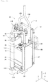
Fig. 2] Fig. 2 is a perspective view showing the atmospheric pressure plasma generator. - [
Fig. 3] Fig. 3 is a sectional view showing a plasma gas ejection device and a heating gas supply device. - [
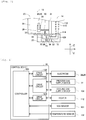
Fig. 4] Fig. 4 is a block diagram showing a control system of the atmospheric pressure plasma generator. - [
Fig. 5] Fig. 5 is a graph showing correlations between generation source temperature and NOx concentration and Ozone concentration. - As shown in
Fig. 1 , atmosphericpressure plasma generator 10 includesplasma head 11,main body section 17,power cable 40, andgas pipe 80 and the like.Main body section 17 includes processgas supply device 77 and coolinggas supply device 102. In atmosphericpressure plasma generator 10, power is transferred frommain body section 17 toplasma head 11 viapower cable 40, a process gas is supplied toplasma head 11 throughgas pipe 80, and a plasma gas is irradiated fromplasma head 11. When referred to herein, the process gas refers to a gas in which an active gas such as oxygen and an inert gas such as nitrogen are mixed together at an arbitrary ratio, and the plasma gas refers to an oxygen plasma gas.Plasma head 11 is attached to a distal end ofrobot arm 141 ofindustrial robot 140.Power cable 40 andgas pipe 80 are attached in such a manner as to extend alongrobot arm 141.Robot arm 141 is an articulated robot in which twoarm sections Industrial robot 140drives robot arm 141 to execute an operation of irradiating a plasma gas on to workpiece W supported on work table 5. - As shown in
Fig. 2 ,plasma head 11 has plasmagas ejection device 12 and heatinggas supply device 14. In the following description, a width direction ofplasma head 11 refers to an X-direction, a depth direction of atmosphericpressure plasma generator 10 refers to a Y-direction, and a direction at right angles to the X direction and the Y-direction, that is, an up-down direction refers to a Z direction. - Plasma
gas ejection device 12 is configured ofupper housing 19,lower housing 20,lower cover 22, pair of electrodes 24, 26 (Fig. 3 ), and pair ofheatsinks Upper housing 19 andlower housing 20 are coupled together viarubber seal member 29 in such a state thatupper housing 19 is placed onlower housing 20. Then,upper housing 19 andlower housing 20, which are coupled together, are held by pair ofheatsinks - As will be described later, a plasma gas is generated in
reaction chamber 38 defined in an interior oflower housing 20, and the plasma gas so generated is ejected downwards from a lower face oflower cover 22.Heatsinks upper housing 19,lower housing 20, and the like. A flow path reaching fromsupply port 96 toexhaust port 98 is formed in an interior of each ofheatsinks port 96 by way ofsupply pipe 100. The cooling gas is warmed up through heat exchange and is then let out fromexhaust port 98. - Heating
gas supply device 14 hasgas pipe 110,heater 112, andcoupling block 114.Gas pipe 110 is connected to the flow paths defined in the interiors ofheatsinks gas pipe 110 is connected toexhaust ports 98 of pair ofheatsinks exhaust pipe 116 at an upper end portion thereof.Exhaust pipe 116 is bifurcated at a first end portion, and end portions of resulting bifurcatedexhaust pipes 16 are coupled tocorresponding exhaust ports 98 of pair ofheatsinks exhaust pipe 116 is not bifurcated at a second end portion and is connected to an upper end ofgas pipe 110. As a result, gas exhausted from pair ofheatsinks gas pipe 110.Heater 112, having a substantially cylindrical shape, is disposed around an outer peripheral surface ofgas pipe 110, so thatgas pipe 110 is heated byheater 112. As a result, the gas supplied fromheatsinks gas pipe 110 is heated. - Next, an internal structure of plasma
gas ejection device 12 will be described usingFig. 3 .Lower housing 20 includesmain housing 30, heat dissipation plate 31,earth plate 32,coupling block 34, andnozzle block 36.Main housing 30 has a block-like shape in general, andreaction chamber 38 is formed in an interior ofmain housing 30.Reaction chamber 38 has an inlet port (not shown) through which a process gas flows in andoutlet port 39 through which a plasma gas flows out. - Earth
plate 32 functions as a lightning rod and is fixed to a lower face ofmain housing 30.Coupling block 34 is fixed to a lower face ofearth plate 32, andnozzle block 36 is fixed to a lower face ofcoupling block 34. Heat dissipation plate 31 is disposed on a side face ofmain housing 30. Heat dissipation plate 31 has multiple fins (not shown), through which heat ofmain housing 30 is dissipated. Gas flow path 50 is formed inmain housing 30,earth plate 32,coupling block 34, andnozzle block 36. Gas flow path 50 communicates withoutlet port 39 ofreaction chamber 38 at a first end and opens to a lower face ofnozzle block 36 at a second end thereof. Opening of gas flow path 50 innozzle block 36 constitutesoutlet port 51. -
Coupling block 114 is coupled to a lower end ofgas pipe 110 and is fixed to a side face oflower cover 22 which faces heatinggas supply device 14 in the Y-direction.Communication path 120 is formed incoupling block 114, andcommunication path 120 opens to an upper face ofcoupling block 114 at a first end portion, andcommunication path 120 opens to a side face ofcoupling block 114 which faces plasmagas ejection device 12 in the Y-direction at a second end portion thereof. Then,communication path 120 communicates with the lower end ofgas pipe 110 at the first end portion, andcommunication path 120 communicates with throughhole 72 inlower cover 22 at the second end portion thereof. As a result, a gas heated ingas pipe 110 is supplied intolower cover 22. - In a control system of atmospheric
pressure plasma generator 10, as shown inFig. 4 ,control device 16 is connected with processgas supply device 77 and coolinggas supply device 102 in such a manner as to communicate with each other, so that the individual sections are controlled bycontrol device 16.Control device 16 hascontroller 130, which is configured mainly of a computer, anddrive circuits 132 to 134.Drive circuit 132 constitutes a circuit for controlling power to be supplied to electrodes 24, 26.Drive circuit 133 constitutes a circuit for controlling flow rates of gases supplied by processgas supply device 77 and coolinggas supply device 102.Drive circuit 134 constitutes a circuit for controlling power supplied toheater 112. In addition,NOx sensor 151 andtemperature sensor 152 are disposed nearoutlet port 51. A signal indicating a concentration of NOx, which is detected byNOx sensor 151, is output tocontroller 130. A signal indicating a temperature, which is detected bytemperature sensor 152, is output tocontroller 130. - In atmospheric
pressure plasma generator 10, plasmagas ejection device 12 is configured as described above, and in plasmagas ejection device 12, a process gas is plasmatized in the interior ofreaction chamber 38, which turns out ejecting plasma gas from a lower end ofnozzle block 36. Specifically speaking, a process gas is supplied to the interior ofreaction chamber 38 by processgas supply device 77. As this occurs, inreaction chamber 38, a voltage is applied to pair of electrodes 24, 26, which are incorporated inreaction chamber 38, and a current flows between pair of electrodes 24, 26. As a result, a discharge is generated between pair of electrodes 24, 26, whereby the process gas is plasmatized by the discharge, and resulting plasma gas is ejected. In the following description, an ejection of a plasma gas may be referred to as a plasma irradiation from time to time. In the case that heatsinks 27, 28 are not provided, applying a voltage to electrodes 24, 26 under plasmatizing increases a temperature ofreaction chamber 38. In atmosphericpressure plasma generator 10, however, a cooling gas is supplied into the flow paths inheatsinks gas supply device 102, wherebyreaction chamber 38 is cooled through heat exchange. The cooling gas that flows through the flow paths inheatsinks gas pipe 110 and is then heated byheater 112. The cooling gas so heated is then supplied into an interior oflower cover 22 and is then ejected against the plasma gas from throughhole 70 inlower cover 22. In addition, throughhole 70 is situated in the vicinity ofnozzle block 36 and is disposed in the flow path of the plasma gas ejected from the lower end ofnozzle block 36. Then, the plasma gas is ejected from throughhole 70 inlower cover 22 together with the heated cooling gas. The plasma gas is heated by the heated cooling gas so ejected. Sinceheater 112 is controlled bycontrol device 16, the temperature of the plasma gas is also controlled. - In the present embodiment, oxygen plasma is generated in atmospheric
pressure plasma generator 10. It is known that oxygen plasma is combined with oxygen to generate ozone. The inventors measured a concentration of NOx generated in atmosphericpressure plasma generator 10 this time.Fig. 5 is a graph showing concentrations of ozone (a solid line) and NOx (a broken line) with respect to source temperatures. When referred to herein, a source temperature means a temperature in the vicinity, for example, ofoutlet port 51. For example, a reaction between oxygen radical and nitrogen or a reaction between oxygen and nitrogen under a high-temperature condition can be considered as a NOx generation mechanism. As shown inFig. 5 , it is found that an amount of generation of ozone increases higher as the temperature decreases lower in a temperature range from 100 and 700°C and that an amount of generation of NOx increases higher as the temperature increases higher in a temperature range from 100 and 1300°C. It is considered that the reason that the ozone concentration does not take a concentration indicated by an alternate long and short dash line, that is, a concentration of almost zero but takes a concentration indicated by a solid line at 700 ° C or higher is that NOx reacts with oxygen to thereby generate ozone. It is considered from the reasoning above that the concentration of ozone increases as the concentration of NOx increases. Ozone naturally returns to oxygen, but NOx is not decomposed spontaneously, so when NOx is generated, it is necessary to install a removing device or the like. For this time, paying attention to the temperature dependency of the NOx concentration, the inventors have contrived a control designed to be performed in atmosphericpressure plasma generator 10 as below. - For irradiation of plasma,
control device 16 controls the temperature of a plasma gas so that an amount of generation of NOx becomes a threshold or smaller. Specifically speaking,control device 16controls heater 112 based on a signal output fromNOx sensor 151 so that the concentration of NOx becomes the threshold or smaller. Here, the threshold needs to take a value based on, for example, a regulation value regulated by a relevant low or the like. Incidentally, in the present embodiment,reaction chamber 38 is cooled by coolinggas supply device 102, and the temperature ofreaction chamber 38 falls down substantially to a temperature ranging from 300 to 400° C. As the temperature of a plasma gas is higher, for example, the effect of plasma irradiation such as imparting hydrophilicity to an object to which plasma is irradiated is improved. Due to this, in the present embodiment, the plasma gas is configured to be heated by the cooling gas which is heated byheater 112. As shown inFig. 5 , when the temperature becomes about 600°C or higher, the concentration of NOx becomes greater than zero. Then, the threshold is set, for example, at a value that slightly exceeds 0 [ppm], andheater 112 is configured to be controlled based on an output signal fromNOx sensor 151 so that the concentration of NOx is not greater than the threshold. - More specifically, the threshold is stored in advance in
controller 130. Then, for irradiation of plasma, when a concentration of NOx indicated by an output signal fromNOx sensor 151 becomes the threshold or greater,control device 16 causesheater 112 to stop heating. Further,control device 16controls heater 112 based on a signal output fromtemperature sensor 152 so that the temperature becomes a target temperature. For example, in the case that an object to which plasma is irradiated is made of resin, the object is damaged in the event that a plasma gas is irradiated to the object with temperature higher than the temperature of a melting point of the resin. Then,control device 16 switches on or offheater 12 to cause the cooling gas to heat so that the temperature of the plasma gas becomes its target temperature, the value of which is stored in advance incontroller 130. As a result, the temperature of the plasma gas can be set to the target temperature while keeping the amount of generation of NOx at the threshold or smaller. - In the embodiment described heretofore, electrodes 24, 26 represent an example of a pair of electrodes.
Heater 112 represents an example of a heater, andheatsinks outlet port 51 represents an example of a flow path of a plasma gas. The cooling gas represents an example of a cooling heating gas,coupling block 114 andlower cover 22 represent an example of a coupling section, and throughhole 70 represents an example of an ejection port. Heatinggas supply device 14 andlower cover 22 represent an example of a heating device. - Thus, with the embodiment that has been described heretofore, the following advantageous effects are provided.
Control device 16controls heater 112 based on a signal output fromNOx sensor 151 so that the concentration of NOx becomes the threshold or smaller. As a result, the amount of generation of NOx can be limited to the threshold or smaller. In addition,control device 16 controls based on a signal output bytemperature sensor 152 so that the temperature becomes the target temperature. As a result, the temperature of the plasma gas can be set to a temperature corresponding to an object to which the plasma gas is irradiated. Further, heatinggas supply device 14 heats the cooling gas flowing throughgas pipe 110 usingheater 112. The plasma gas is heated by ejection of the heated cooling gas. As a result, the temperature of the plasma gas can be controlled by controllingheater 112. - Next, Alternative Example 1 will be described in which atmospheric
pressure plasma generator 10 does not includetemperature sensor 152 but includesNOx sensor 151. In the case of this configuration,control device 16controls heater 112 based on a signal output byNOx sensor 151 so that the concentration of NOx becomes the threshold or smaller. As a result, the amount of generation of NOx can be limited to the threshold or smaller. - Next, Alternative Example 2 will be described in which atmospheric
pressure plasma generator 10 does not includeNOx sensor 151 but includestemperature sensor 152 and an ozone sensor (not shown). In the case of this configuration,control device 16controls heater 112 based on a signal output by the ozone sensor so that a concentration of ozone becomes a predetermined value or greater. As shown inFig. 5 , with the concentration of ozone staying in a temperature range of up to about 800 °C, an amount of generation of ozone decreases as the temperature increases. On the other hand, the concentration of NOx increases as the temperature increases, and when the temperature exceeds about 600°C, the concentration of NOx becomes greater than zero. Consequently, since the concentration of ozone and the concentration of NOx are both dependent on temperature, the concentration of NOx can be estimated based on the concentration of ozone. Specifically speaking, correlation data between the concentration of ozone and the concentration of NOx is measured, and a value at which the concentration of NOx becomes the threshold or smaller is determined as a lower limit value for the concentration of ozone. Then, the lower limit value for the concentration of ozone so determined is stored incontroller 130. Then, for irradiation of plasma, when a concentration of ozone indicated by an output signal from the ozone sensor becomes smaller than the lower limit value,control device 16 causesheater 112 to stop heating. Further,control device 16controls heater 112 based on a signal output fromtemperature sensor 152 so that the temperature becomes a target temperature. As a result, the temperature of the plasma gas can be adjusted to a temperature corresponding to an object to which the plasma gas is irradiated while maintaining the concentration of NOx to the threshold or smaller. - Next, Alternative Example 3 will be described in which atmospheric
pressure plasma generator 10 does not includeNOx sensor 151 andtemperature sensor 152 but includes an ozone sensor (not shown). In the case of this configuration, as in the case with (Alternative Example 2), correlation data between the concentration of ozone and the concentration of NOx is measured, and a value at which the concentration of NOx becomes the regulation value or smaller is determined as a lower limit value for the concentration of ozone. Then, the lower limit value for the concentration of ozone so determined is stored incontroller 130. Then, for irradiation of plasma, when a concentration of ozone indicated by an output signal from the ozone sensor becomes smaller than the lower limit value,control device 16 causesheater 112 to stop heating. As a result, the concentration of NOx can be set to the threshold value or smaller. - Next, Alternative Example 4 will be described in which atmospheric
pressure plasma generator 10 does not includetemperature sensor 152 but includesNOx sensor 151 and an ozone sensor (not shown) . In the case of this configuration, as in the case with (Another Example 2), correlation data between the concentration of ozone and the concentration of NOx is measured, and a value at which the concentration of NOx becomes the threshold or smaller is determined as a lower limit value for the concentration of ozone. Then, the lower limit value for the concentration of ozone so determined is stored incontroller 130. For irradiation of plasma, when a concentration of NOx indicated by an output signal fromNOx sensor 151 becomes the threshold or greater,control device 16 causesheater 112 to stop heating, and when a centration of ozone indicated by an output signal from the ozone sensor becomes the lower limit value or smaller,control device 16 causesheater 112 to stop heating. As a result, an amount of generation of NOx can be set at the threshold or smaller in an ensured fashion. - Next, Alternative Example 5 will be described in which atmospheric
pressure plasma generator 10 includesNOx sensor 151,temperature sensor 152, and an ozone sensor (not shown). In the case of this configuration, as in the case with (Alternative Example 4), for irradiation of plasma, when a concentration of NOx indicated by an output signal fromNOx sensor 151 becomes the threshold or smaller,control device 16 causesheater 112 to stop heating, and when a concentration of ozone indicated by an output signal from the ozone sensor becomes the lower limit value or smaller,control device 16 causesheater 112 to stop heating. Further,control device 16 switches on or offheater 12 to cause the cooling gas to heat the cooling gas so that the temperature of the plasma gas becomes its target temperature, the value of which being stored in advance incontroller 130. As a result, the temperature of the plasma gas can be set to the target temperature while keeping the amount of generation of NOx at the threshold or smaller in an ensured fashion. - Next, Alternative Example 6 will be described in which atmospheric
pressure plasma generator 10 does not includeNOx sensor 151 but includestemperature sensor 152. In the case of this configuration, correlation data between the concentration of NOx and the temperature is measured, and a value at which the concentration of NOx becomes the threshold or smaller is determined as an upper limit value for the temperature. Then, the upper limit value of the temperature so determined is stored incontroller 130. For irradiation of plasma, when a temperature indicated by an output signal fromtemperature sensor 152 becomes greater than the upper limit value,control device 16 causesheater 112 to stop heating. As a result, the amount of generation of NOx can be maintained at the threshold or smaller. - Next, Alternative Example 7 will be described in which atmospheric
pressure plasma generator 10 does not includeheater 112 but includes a cooling device (not shown). The embodiment described above adopts the configuration in whichreaction chamber 38 is cooled by coolinggas supply device 102, and the plasma gas is heated by the cooling gas heated byheater 112. Since the temperature inreaction chamber 38 rises as a result of application of the voltage to electrodes 24, 26, in the event thatreaction chamber 38 is not cooled, the temperature of the plasma gas reaches, for example, a temperature of the order of 1000°C. In (Alternative Example 7),heater 112 is not provided, and a configuration is adopted in whichreaction chamber 38 is cooled by the cooling device by taking into consideration a temperature increase inreaction chamber 38 occurring due to the absence ofheater 112 so that the temperature of the plasma gas becomes a set temperature. As a cooling device, for example, a configuration is considered in which a feedback control circuit is added in drivingcircuit 133, the feed back control circuit being configured to adjust a flow rate of a cooling gas which is supplied by coolinggas supply device 102 based on an output signal fromtemperature sensor 152. That is, in the event that a temperature indicated bytemperature sensor 152 is higher than the set temperature, the flow rate of the cooling gas is increased, while in the event that the temperature indicated bytemperature sensor 152 is lower than the set temperature, the flow rate of the cooling gas is decreased, whereby the flow rate of the cooling gas is controlled so that the temperature of the plasma gas stays at the set temperature. - In the case of this configuration,
control device 16 controls the cooling device based on a signal output byNOx sensor 151 so that the concentration of NOx becomes the threshold or smaller. As a result, the amount of generation of NOx can be limited to the threshold or smaller. In addition,control device 16 controls the cooling device based on a signal output bytemperature sensor 152 so that the temperature becomes the target temperature. As a result, the temperature of the plasma gas can be set to a temperature corresponding to an object to which the plasma gas is irradiated. A configuration may be adopted in which any one of the configurations of (Alternative Example 1) to (Alternative Example 6) and the configuration of (Alternative Example 7) are combined with each other arbitrarily. That is, in the configurations of (Alternative Example 1) to (Alternative Example 6), the cooling device may be configured so as to be controlled based on an output signal of each of the sensors. - The present invention is not limited to the embodiment that has been described heretofore, and hence, needless to say, various improvements and alterations or modifications can be made thereto without departing from the spirit and scope of the present invention. For example, in the embodiment described above,
heatsinks heatsinks reaction chamber 38; however, for example, a configuration may be adopted in which the process gas is cooled by a vortex tube, or a configuration may be adopted in which both the process gas andreaction chamber 38 are cooled. Further, in the case of (Alternative Example 7), too, in addition to the configuration in which the cooling device coolsreaction chamber 38, a configuration may be adopted in which the cooling device cools the process gas, or a configuration may be adopted in which the cooling device cools both the process gas andreaction chamber 38. - In addition, in the embodiment described above,
NOx sensor 151 andtemperature sensor 152 are described as being disposed in the vicinity ofoutlet port 51; however, the present invention is not limited thereto. For example, a configuration may be adopted in whichtemperature sensor 152 andNOx sensor 151 are disposed inreaction chamber 38 and gas flow path 50, respectively. - Further, in (Alternative Example 7), the configuration is described in which
heater 112 is not provided; however, a configuration may be adopted in which bothheater 112 and the cooling device are provided, andcontrol device 16controls heater 112 and the cooling device so that the temperature of the plasma gas becomes the set temperature. - Furthermore, in the embodiment described above, atmospheric
pressure plasma generator 10 is described as includingNOx sensor 151 andtemperature sensor 152; however, a configuration may be adopted in which an open-loop control is performed without those sensors. Specifically speaking, control conditions ofheater 112 under which an amount of generation of NOx becomes the threshold or smaller are obtained through experiments and the like. For irradiation of plasma, a control is performed by following these control conditions. - Additionally, in the embodiment described above, as one example of the heating device, the configuration is described in which the plasma gas is heated by ejecting the cooling gas heated by
heater 112; however, the present invention is not limited thereto. For example, a configuration may be adopted in which the plasma gas is heated directly by a heater or the like. - Further, in the embodiment described above,
lower housing 20 is described as havingearth plate 32; however, the present invention is not limited thereto, and hence, a configuration may be adopted in whichlower housing 20 does not haveearth plate 32. - 10 Atmospheric Pressure Plasma Generator, 14 Heating Gas Supply Device, 16 Control Device, 22 Lower Cover, 24, 26 Electrode, 27, 28 Heatsink, 38 Reaction Chamber, 110 Gas Pipe, 112 Heater, 114 Coupling Block
Claims (7)
- An atmospheric pressure plasma generator comprising:a pair of electrodes for generating plasma by discharge;a reaction chamber incorporating the pair of electrodes and having an inlet port through which a process gas flows in and an outlet port through which a plasma gas flows out as a result of the process gas being plasmatized by the pair of electrodes, anda control device for controlling a temperature of the plasma gas flowing out from the outlet port so that an amount of generation of NOx becomes a threshold orsmaller.
- The atmospheric pressure plasma generator according to claim 1, comprising:a NOx sensor disposed in a flow path of the plasma gas,wherein the control device performs the control based on an output from the NOx sensor.
- The atmospheric pressure plasma generator according to claim 1 or 2,
wherein the plasma gas is an oxygen plasma gas,
wherein the atmospheric pressure plasma generator comprises an ozone sensor disposed in the flow path of the plasma gas, and
wherein the control device controls a temperature of the plasma gas based on an output from the ozone sensor so that an amount of generation of ozone falls in a range of a predetermined value or greater. - The atmospheric pressure plasma generator according to any one of claims 1 to 3, comprising:a temperature sensor disposed in the flow path of the plasma gas,wherein the control device controls so that a temperature based on an output from the temperature sensor becomes a target temperature.
- The atmospheric pressure plasma generator according to any one of claims 1 to 4, comprising:a cooling device for cooling at least either of the process gas and the reaction chamber,wherein the control device controls a temperature of the plasma gas by controlling the cooling device.
- The atmospheric pressure plasma generator according to any one of claims 1 to 5, comprising:a cooler for cooling at least either of the process gas and the reaction chamber;anda heating device for heating the plasma gas,wherein the control device controls a temperature of the plasma gas by controlling the heating device.
- The atmospheric pressure plasma generator according to claim 6,
wherein the cooler has a gas flow path through which a cooling heating gas flows,
wherein the heating device has:a gas pipe coupled to the gas flow path and through which the cooling heating gas flows;a heater disposed in the gas pipe; anda coupling section coupled to the gas pipe and having an ejection port opening to a flow path of the plasma gas, andwherein the plasma gas is heated as a result of the cooling heating gas heated by the heater being ejected from the ejection port against the plasma gas.
Applications Claiming Priority (1)
| Application Number | Priority Date | Filing Date | Title |
|---|---|---|---|
| PCT/JP2018/028989 WO2020026400A1 (en) | 2018-08-02 | 2018-08-02 | Atmospheric-pressure plasma generator |
Publications (3)
| Publication Number | Publication Date |
|---|---|
| EP3832697A1 true EP3832697A1 (en) | 2021-06-09 |
| EP3832697A4 EP3832697A4 (en) | 2021-08-04 |
| EP3832697B1 EP3832697B1 (en) | 2023-06-07 |
Family
ID=69231652
Family Applications (1)
| Application Number | Title | Priority Date | Filing Date |
|---|---|---|---|
| EP18928948.1A Active EP3832697B1 (en) | 2018-08-02 | 2018-08-02 | Atmospheric-pressure plasma generator |
Country Status (4)
| Country | Link |
|---|---|
| EP (1) | EP3832697B1 (en) |
| JP (1) | JP6983322B2 (en) |
| CN (1) | CN112543990B (en) |
| WO (1) | WO2020026400A1 (en) |
Families Citing this family (1)
| Publication number | Priority date | Publication date | Assignee | Title |
|---|---|---|---|---|
| CN115175426A (en) * | 2022-07-14 | 2022-10-11 | 中国科学院苏州生物医学工程技术研究所 | Variable-temperature atmospheric pressure plasma generating device |
Family Cites Families (16)
| Publication number | Priority date | Publication date | Assignee | Title |
|---|---|---|---|---|
| JPH10185137A (en) * | 1998-02-04 | 1998-07-14 | Satoru Yoshinaka | Semi-dry distillation gasification incineration method and device thereof |
| JP4090827B2 (en) * | 2002-09-09 | 2008-05-28 | 独立行政法人科学技術振興機構 | Photocatalyst using composite oxide containing metal ions in d10s2 and d0 electronic states |
| JP2004165377A (en) * | 2002-11-12 | 2004-06-10 | Canon Inc | Surface modification method |
| JP4093902B2 (en) * | 2003-04-14 | 2008-06-04 | 三菱電機株式会社 | Ozone generator |
| JP5121142B2 (en) * | 2003-04-30 | 2013-01-16 | 富士通セミコンダクター株式会社 | Manufacturing method of semiconductor device |
| JP4998456B2 (en) * | 2004-04-08 | 2012-08-15 | 三菱電機株式会社 | Ozone generator and ozone generation method |
| JP2007265838A (en) * | 2006-03-29 | 2007-10-11 | Noritsu Koki Co Ltd | Plasma generating apparatus and work processing apparatus using the same |
| TW200829325A (en) * | 2007-01-15 | 2008-07-16 | Kanken Techno Co Ltd | Apparatus and method for processing gas |
| JP5568209B2 (en) * | 2007-03-01 | 2014-08-06 | ピーエスフォー ルクスコ エスエイアールエル | Semiconductor device manufacturing method and manufacturing apparatus |
| JP5420862B2 (en) * | 2008-07-23 | 2014-02-19 | 三井造船株式会社 | High voltage plasma generator |
| JP2012079785A (en) * | 2010-09-30 | 2012-04-19 | Tokyo Electron Ltd | Reforming method of insulation film |
| JP5892904B2 (en) * | 2012-09-25 | 2016-03-23 | 三菱電機株式会社 | Ozone supply system and wastewater treatment system |
| CN107409464A (en) * | 2015-03-20 | 2017-11-28 | 日本碍子株式会社 | Plasma generating method and sterilized water generation method |
| JP6581387B2 (en) * | 2015-05-12 | 2019-09-25 | 株式会社日立ハイテクノロジーズ | Plasma processing apparatus and plasma processing method |
| CN109565921B (en) * | 2016-08-11 | 2021-05-18 | 株式会社富士 | Plasma generator and plasma irradiation method |
| JP6645385B2 (en) * | 2016-08-30 | 2020-02-14 | 株式会社デンソー | Gas reformer |
-
2018
- 2018-08-02 JP JP2020533986A patent/JP6983322B2/en active Active
- 2018-08-02 EP EP18928948.1A patent/EP3832697B1/en active Active
- 2018-08-02 WO PCT/JP2018/028989 patent/WO2020026400A1/en not_active Ceased
- 2018-08-02 CN CN201880096124.0A patent/CN112543990B/en active Active
Also Published As
| Publication number | Publication date |
|---|---|
| EP3832697A4 (en) | 2021-08-04 |
| JP6983322B2 (en) | 2021-12-17 |
| CN112543990B (en) | 2023-10-24 |
| CN112543990A (en) | 2021-03-23 |
| EP3832697B1 (en) | 2023-06-07 |
| JPWO2020026400A1 (en) | 2021-02-25 |
| WO2020026400A1 (en) | 2020-02-06 |
Similar Documents
| Publication | Publication Date | Title |
|---|---|---|
| KR100246724B1 (en) | Laser having improved beam quality and reduced operating cost | |
| JP4071968B2 (en) | Gas supply system and gas supply method | |
| CN109565921B (en) | Plasma generator and plasma irradiation method | |
| JPH04196528A (en) | Magnetron etching system | |
| KR970072122A (en) | Plasma processing method and apparatus | |
| EP3832697B1 (en) | Atmospheric-pressure plasma generator | |
| KR102636955B1 (en) | gas processing system | |
| US12271157B2 (en) | Temperature control system with circulating fluid | |
| US20130210235A1 (en) | Apparatus and method for the rapid thermal control of a work piece in liquid or supercritical fluid | |
| KR102110636B1 (en) | Atmospheric pressure plasma generator, and workpiece pair processing machine | |
| JP2015144078A (en) | Air-pressure plasma generator | |
| JP7200337B2 (en) | Atmospheric pressure plasma generator | |
| US12340974B2 (en) | Hydrogen supply device, and ion beam irradiation apparatus equipped therewith | |
| JPH09213596A (en) | Semiconductor manufacturing method and exhaust gas treatment method and apparatus used therefor | |
| KR102937595B1 (en) | Active temperature control of the RF window in the built-in antenna source | |
| US10772181B2 (en) | Plasma generation device | |
| KR102370846B1 (en) | An Apparatus for Controlling a Temperature of a Thermoelement Module | |
| JP3770409B2 (en) | HMDS supply device | |
| KR200269069Y1 (en) | Cooling gas supply device of plasma etching system | |
| KR100607750B1 (en) | Control Method of Semiconductor Process Chamber | |
| Ranga Janardhana et al. | Experimental analysis of different coolants used in plasma cutting operation for the improved electrode life | |
| JPH11102850A (en) | Substrate-processing device | |
| JPH02143440A (en) | Wafer chuck of semiconductor wafer processing equipment | |
| JP2008153148A (en) | Plasma processing equipment | |
| JPH0774105A (en) | Semiconductor manufacturing equipment |
Legal Events
| Date | Code | Title | Description |
|---|---|---|---|
| STAA | Information on the status of an ep patent application or granted ep patent |
Free format text: STATUS: THE INTERNATIONAL PUBLICATION HAS BEEN MADE |
|
| PUAI | Public reference made under article 153(3) epc to a published international application that has entered the european phase |
Free format text: ORIGINAL CODE: 0009012 |
|
| STAA | Information on the status of an ep patent application or granted ep patent |
Free format text: STATUS: REQUEST FOR EXAMINATION WAS MADE |
|
| 17P | Request for examination filed |
Effective date: 20210118 |
|
| AK | Designated contracting states |
Kind code of ref document: A1 Designated state(s): AL AT BE BG CH CY CZ DE DK EE ES FI FR GB GR HR HU IE IS IT LI LT LU LV MC MK MT NL NO PL PT RO RS SE SI SK SM TR |
|
| A4 | Supplementary search report drawn up and despatched |
Effective date: 20210702 |
|
| RIC1 | Information provided on ipc code assigned before grant |
Ipc: H01L 21/3065 20060101AFI20210628BHEP Ipc: H01J 37/32 20060101ALI20210628BHEP Ipc: H05H 1/46 20060101ALI20210628BHEP |
|
| DAV | Request for validation of the european patent (deleted) | ||
| DAX | Request for extension of the european patent (deleted) | ||
| GRAP | Despatch of communication of intention to grant a patent |
Free format text: ORIGINAL CODE: EPIDOSNIGR1 |
|
| STAA | Information on the status of an ep patent application or granted ep patent |
Free format text: STATUS: GRANT OF PATENT IS INTENDED |
|
| RIC1 | Information provided on ipc code assigned before grant |
Ipc: H05H 1/46 20060101ALI20230130BHEP Ipc: H01J 37/32 20060101ALI20230130BHEP Ipc: H01L 21/3065 20060101AFI20230130BHEP |
|
| INTG | Intention to grant announced |
Effective date: 20230301 |
|
| GRAS | Grant fee paid |
Free format text: ORIGINAL CODE: EPIDOSNIGR3 |
|
| GRAA | (expected) grant |
Free format text: ORIGINAL CODE: 0009210 |
|
| STAA | Information on the status of an ep patent application or granted ep patent |
Free format text: STATUS: THE PATENT HAS BEEN GRANTED |
|
| AK | Designated contracting states |
Kind code of ref document: B1 Designated state(s): AL AT BE BG CH CY CZ DE DK EE ES FI FR GB GR HR HU IE IS IT LI LT LU LV MC MK MT NL NO PL PT RO RS SE SI SK SM TR |
|
| REG | Reference to a national code |
Ref country code: GB Ref legal event code: FG4D |
|
| P01 | Opt-out of the competence of the unified patent court (upc) registered |
Effective date: 20230328 |
|
| REG | Reference to a national code |
Ref country code: CH Ref legal event code: EP Ref country code: AT Ref legal event code: REF Ref document number: 1577529 Country of ref document: AT Kind code of ref document: T Effective date: 20230615 |
|
| REG | Reference to a national code |
Ref country code: DE Ref legal event code: R096 Ref document number: 602018051696 Country of ref document: DE |
|
| REG | Reference to a national code |
Ref country code: LT Ref legal event code: MG9D |
|
| REG | Reference to a national code |
Ref country code: NL Ref legal event code: MP Effective date: 20230607 |
|
| PG25 | Lapsed in a contracting state [announced via postgrant information from national office to epo] |
Ref country code: SE Free format text: LAPSE BECAUSE OF FAILURE TO SUBMIT A TRANSLATION OF THE DESCRIPTION OR TO PAY THE FEE WITHIN THE PRESCRIBED TIME-LIMIT Effective date: 20230607 Ref country code: NO Free format text: LAPSE BECAUSE OF FAILURE TO SUBMIT A TRANSLATION OF THE DESCRIPTION OR TO PAY THE FEE WITHIN THE PRESCRIBED TIME-LIMIT Effective date: 20230907 Ref country code: ES Free format text: LAPSE BECAUSE OF FAILURE TO SUBMIT A TRANSLATION OF THE DESCRIPTION OR TO PAY THE FEE WITHIN THE PRESCRIBED TIME-LIMIT Effective date: 20230607 |
|
| REG | Reference to a national code |
Ref country code: AT Ref legal event code: MK05 Ref document number: 1577529 Country of ref document: AT Kind code of ref document: T Effective date: 20230607 |
|
| PG25 | Lapsed in a contracting state [announced via postgrant information from national office to epo] |
Ref country code: RS Free format text: LAPSE BECAUSE OF FAILURE TO SUBMIT A TRANSLATION OF THE DESCRIPTION OR TO PAY THE FEE WITHIN THE PRESCRIBED TIME-LIMIT Effective date: 20230607 Ref country code: NL Free format text: LAPSE BECAUSE OF FAILURE TO SUBMIT A TRANSLATION OF THE DESCRIPTION OR TO PAY THE FEE WITHIN THE PRESCRIBED TIME-LIMIT Effective date: 20230607 Ref country code: LV Free format text: LAPSE BECAUSE OF FAILURE TO SUBMIT A TRANSLATION OF THE DESCRIPTION OR TO PAY THE FEE WITHIN THE PRESCRIBED TIME-LIMIT Effective date: 20230607 Ref country code: LT Free format text: LAPSE BECAUSE OF FAILURE TO SUBMIT A TRANSLATION OF THE DESCRIPTION OR TO PAY THE FEE WITHIN THE PRESCRIBED TIME-LIMIT Effective date: 20230607 Ref country code: HR Free format text: LAPSE BECAUSE OF FAILURE TO SUBMIT A TRANSLATION OF THE DESCRIPTION OR TO PAY THE FEE WITHIN THE PRESCRIBED TIME-LIMIT Effective date: 20230607 Ref country code: GR Free format text: LAPSE BECAUSE OF FAILURE TO SUBMIT A TRANSLATION OF THE DESCRIPTION OR TO PAY THE FEE WITHIN THE PRESCRIBED TIME-LIMIT Effective date: 20230908 |
|
| PG25 | Lapsed in a contracting state [announced via postgrant information from national office to epo] |
Ref country code: FI Free format text: LAPSE BECAUSE OF FAILURE TO SUBMIT A TRANSLATION OF THE DESCRIPTION OR TO PAY THE FEE WITHIN THE PRESCRIBED TIME-LIMIT Effective date: 20230607 |
|
| PG25 | Lapsed in a contracting state [announced via postgrant information from national office to epo] |
Ref country code: SK Free format text: LAPSE BECAUSE OF FAILURE TO SUBMIT A TRANSLATION OF THE DESCRIPTION OR TO PAY THE FEE WITHIN THE PRESCRIBED TIME-LIMIT Effective date: 20230607 |
|
| PG25 | Lapsed in a contracting state [announced via postgrant information from national office to epo] |
Ref country code: IS Free format text: LAPSE BECAUSE OF FAILURE TO SUBMIT A TRANSLATION OF THE DESCRIPTION OR TO PAY THE FEE WITHIN THE PRESCRIBED TIME-LIMIT Effective date: 20231007 |
|
| PG25 | Lapsed in a contracting state [announced via postgrant information from national office to epo] |
Ref country code: SM Free format text: LAPSE BECAUSE OF FAILURE TO SUBMIT A TRANSLATION OF THE DESCRIPTION OR TO PAY THE FEE WITHIN THE PRESCRIBED TIME-LIMIT Effective date: 20230607 Ref country code: SK Free format text: LAPSE BECAUSE OF FAILURE TO SUBMIT A TRANSLATION OF THE DESCRIPTION OR TO PAY THE FEE WITHIN THE PRESCRIBED TIME-LIMIT Effective date: 20230607 Ref country code: RO Free format text: LAPSE BECAUSE OF FAILURE TO SUBMIT A TRANSLATION OF THE DESCRIPTION OR TO PAY THE FEE WITHIN THE PRESCRIBED TIME-LIMIT Effective date: 20230607 Ref country code: PT Free format text: LAPSE BECAUSE OF FAILURE TO SUBMIT A TRANSLATION OF THE DESCRIPTION OR TO PAY THE FEE WITHIN THE PRESCRIBED TIME-LIMIT Effective date: 20231009 Ref country code: IS Free format text: LAPSE BECAUSE OF FAILURE TO SUBMIT A TRANSLATION OF THE DESCRIPTION OR TO PAY THE FEE WITHIN THE PRESCRIBED TIME-LIMIT Effective date: 20231007 Ref country code: EE Free format text: LAPSE BECAUSE OF FAILURE TO SUBMIT A TRANSLATION OF THE DESCRIPTION OR TO PAY THE FEE WITHIN THE PRESCRIBED TIME-LIMIT Effective date: 20230607 Ref country code: CZ Free format text: LAPSE BECAUSE OF FAILURE TO SUBMIT A TRANSLATION OF THE DESCRIPTION OR TO PAY THE FEE WITHIN THE PRESCRIBED TIME-LIMIT Effective date: 20230607 Ref country code: AT Free format text: LAPSE BECAUSE OF FAILURE TO SUBMIT A TRANSLATION OF THE DESCRIPTION OR TO PAY THE FEE WITHIN THE PRESCRIBED TIME-LIMIT Effective date: 20230607 |
|
| PG25 | Lapsed in a contracting state [announced via postgrant information from national office to epo] |
Ref country code: PL Free format text: LAPSE BECAUSE OF FAILURE TO SUBMIT A TRANSLATION OF THE DESCRIPTION OR TO PAY THE FEE WITHIN THE PRESCRIBED TIME-LIMIT Effective date: 20230607 |
|
| REG | Reference to a national code |
Ref country code: DE Ref legal event code: R097 Ref document number: 602018051696 Country of ref document: DE |
|
| PG25 | Lapsed in a contracting state [announced via postgrant information from national office to epo] |
Ref country code: MC Free format text: LAPSE BECAUSE OF FAILURE TO SUBMIT A TRANSLATION OF THE DESCRIPTION OR TO PAY THE FEE WITHIN THE PRESCRIBED TIME-LIMIT Effective date: 20230607 |
|
| REG | Reference to a national code |
Ref country code: CH Ref legal event code: PL |
|
| PG25 | Lapsed in a contracting state [announced via postgrant information from national office to epo] |
Ref country code: MC Free format text: LAPSE BECAUSE OF FAILURE TO SUBMIT A TRANSLATION OF THE DESCRIPTION OR TO PAY THE FEE WITHIN THE PRESCRIBED TIME-LIMIT Effective date: 20230607 |
|
| PLBE | No opposition filed within time limit |
Free format text: ORIGINAL CODE: 0009261 |
|
| STAA | Information on the status of an ep patent application or granted ep patent |
Free format text: STATUS: NO OPPOSITION FILED WITHIN TIME LIMIT |
|
| PG25 | Lapsed in a contracting state [announced via postgrant information from national office to epo] |
Ref country code: LU Free format text: LAPSE BECAUSE OF NON-PAYMENT OF DUE FEES Effective date: 20230802 |
|
| PG25 | Lapsed in a contracting state [announced via postgrant information from national office to epo] |
Ref country code: LU Free format text: LAPSE BECAUSE OF NON-PAYMENT OF DUE FEES Effective date: 20230802 Ref country code: DK Free format text: LAPSE BECAUSE OF FAILURE TO SUBMIT A TRANSLATION OF THE DESCRIPTION OR TO PAY THE FEE WITHIN THE PRESCRIBED TIME-LIMIT Effective date: 20230607 Ref country code: CH Free format text: LAPSE BECAUSE OF NON-PAYMENT OF DUE FEES Effective date: 20230831 |
|
| PG25 | Lapsed in a contracting state [announced via postgrant information from national office to epo] |
Ref country code: SI Free format text: LAPSE BECAUSE OF FAILURE TO SUBMIT A TRANSLATION OF THE DESCRIPTION OR TO PAY THE FEE WITHIN THE PRESCRIBED TIME-LIMIT Effective date: 20230607 |
|
| REG | Reference to a national code |
Ref country code: BE Ref legal event code: MM Effective date: 20230831 |
|
| 26N | No opposition filed |
Effective date: 20240308 |
|
| REG | Reference to a national code |
Ref country code: IE Ref legal event code: MM4A |
|
| GBPC | Gb: european patent ceased through non-payment of renewal fee |
Effective date: 20230907 |
|
| PG25 | Lapsed in a contracting state [announced via postgrant information from national office to epo] |
Ref country code: SI Free format text: LAPSE BECAUSE OF FAILURE TO SUBMIT A TRANSLATION OF THE DESCRIPTION OR TO PAY THE FEE WITHIN THE PRESCRIBED TIME-LIMIT Effective date: 20230607 Ref country code: IT Free format text: LAPSE BECAUSE OF FAILURE TO SUBMIT A TRANSLATION OF THE DESCRIPTION OR TO PAY THE FEE WITHIN THE PRESCRIBED TIME-LIMIT Effective date: 20230607 |
|
| PG25 | Lapsed in a contracting state [announced via postgrant information from national office to epo] |
Ref country code: IE Free format text: LAPSE BECAUSE OF NON-PAYMENT OF DUE FEES Effective date: 20230802 |
|
| PG25 | Lapsed in a contracting state [announced via postgrant information from national office to epo] |
Ref country code: GB Free format text: LAPSE BECAUSE OF NON-PAYMENT OF DUE FEES Effective date: 20230907 |
|
| PG25 | Lapsed in a contracting state [announced via postgrant information from national office to epo] |
Ref country code: IE Free format text: LAPSE BECAUSE OF NON-PAYMENT OF DUE FEES Effective date: 20230802 Ref country code: GB Free format text: LAPSE BECAUSE OF NON-PAYMENT OF DUE FEES Effective date: 20230907 Ref country code: FR Free format text: LAPSE BECAUSE OF NON-PAYMENT OF DUE FEES Effective date: 20230807 |
|
| PG25 | Lapsed in a contracting state [announced via postgrant information from national office to epo] |
Ref country code: BE Free format text: LAPSE BECAUSE OF NON-PAYMENT OF DUE FEES Effective date: 20230831 |
|
| PG25 | Lapsed in a contracting state [announced via postgrant information from national office to epo] |
Ref country code: BG Free format text: LAPSE BECAUSE OF FAILURE TO SUBMIT A TRANSLATION OF THE DESCRIPTION OR TO PAY THE FEE WITHIN THE PRESCRIBED TIME-LIMIT Effective date: 20230607 |
|
| PG25 | Lapsed in a contracting state [announced via postgrant information from national office to epo] |
Ref country code: BG Free format text: LAPSE BECAUSE OF FAILURE TO SUBMIT A TRANSLATION OF THE DESCRIPTION OR TO PAY THE FEE WITHIN THE PRESCRIBED TIME-LIMIT Effective date: 20230607 |
|
| PG25 | Lapsed in a contracting state [announced via postgrant information from national office to epo] |
Ref country code: CY Free format text: LAPSE BECAUSE OF FAILURE TO SUBMIT A TRANSLATION OF THE DESCRIPTION OR TO PAY THE FEE WITHIN THE PRESCRIBED TIME-LIMIT; INVALID AB INITIO Effective date: 20180802 |
|
| PG25 | Lapsed in a contracting state [announced via postgrant information from national office to epo] |
Ref country code: HU Free format text: LAPSE BECAUSE OF FAILURE TO SUBMIT A TRANSLATION OF THE DESCRIPTION OR TO PAY THE FEE WITHIN THE PRESCRIBED TIME-LIMIT; INVALID AB INITIO Effective date: 20180802 |
|
| PGFP | Annual fee paid to national office [announced via postgrant information from national office to epo] |
Ref country code: DE Payment date: 20250702 Year of fee payment: 8 |
|
| REG | Reference to a national code |
Ref country code: DE Ref legal event code: R079 Ref document number: 602018051696 Country of ref document: DE Free format text: PREVIOUS MAIN CLASS: H01L0021306500 Ipc: H10P0050240000 |
|
| PG25 | Lapsed in a contracting state [announced via postgrant information from national office to epo] |
Ref country code: TR Free format text: LAPSE BECAUSE OF FAILURE TO SUBMIT A TRANSLATION OF THE DESCRIPTION OR TO PAY THE FEE WITHIN THE PRESCRIBED TIME-LIMIT Effective date: 20230607 |