EP3832273A1 - Electromagnetic wave detection device and information acquisition system - Google Patents
Electromagnetic wave detection device and information acquisition system Download PDFInfo
- Publication number
- EP3832273A1 EP3832273A1 EP19840084.8A EP19840084A EP3832273A1 EP 3832273 A1 EP3832273 A1 EP 3832273A1 EP 19840084 A EP19840084 A EP 19840084A EP 3832273 A1 EP3832273 A1 EP 3832273A1
- Authority
- EP
- European Patent Office
- Prior art keywords
- electromagnetic waves
- prism
- detector
- detection apparatus
- wave detection
- Prior art date
- Legal status (The legal status is an assumption and is not a legal conclusion. Google has not performed a legal analysis and makes no representation as to the accuracy of the status listed.)
- Granted
Links
Images





Classifications
-
- G—PHYSICS
- G01—MEASURING; TESTING
- G01V—GEOPHYSICS; GRAVITATIONAL MEASUREMENTS; DETECTING MASSES OR OBJECTS; TAGS
- G01V8/00—Prospecting or detecting by optical means
- G01V8/10—Detecting, e.g. by using light barriers
- G01V8/12—Detecting, e.g. by using light barriers using one transmitter and one receiver
- G01V8/18—Detecting, e.g. by using light barriers using one transmitter and one receiver using mechanical scanning systems
-
- H—ELECTRICITY
- H10—SEMICONDUCTOR DEVICES; ELECTRIC SOLID-STATE DEVICES NOT OTHERWISE PROVIDED FOR
- H10F—INORGANIC SEMICONDUCTOR DEVICES SENSITIVE TO INFRARED RADIATION, LIGHT, ELECTROMAGNETIC RADIATION OF SHORTER WAVELENGTH OR CORPUSCULAR RADIATION
- H10F39/00—Integrated devices, or assemblies of multiple devices, comprising at least one element covered by group H10F30/00, e.g. radiation detectors comprising photodiode arrays
- H10F39/80—Constructional details of image sensors
- H10F39/806—Optical elements or arrangements associated with the image sensors
-
- G—PHYSICS
- G01—MEASURING; TESTING
- G01V—GEOPHYSICS; GRAVITATIONAL MEASUREMENTS; DETECTING MASSES OR OBJECTS; TAGS
- G01V3/00—Electric or magnetic prospecting or detecting; Measuring magnetic field characteristics of the earth, e.g. declination, deviation
- G01V3/12—Electric or magnetic prospecting or detecting; Measuring magnetic field characteristics of the earth, e.g. declination, deviation operating with electromagnetic waves
-
- H—ELECTRICITY
- H04—ELECTRIC COMMUNICATION TECHNIQUE
- H04N—PICTORIAL COMMUNICATION, e.g. TELEVISION
- H04N23/00—Cameras or camera modules comprising electronic image sensors; Control thereof
- H04N23/20—Cameras or camera modules comprising electronic image sensors; Control thereof for generating image signals from infrared radiation only
-
- H—ELECTRICITY
- H10—SEMICONDUCTOR DEVICES; ELECTRIC SOLID-STATE DEVICES NOT OTHERWISE PROVIDED FOR
- H10F—INORGANIC SEMICONDUCTOR DEVICES SENSITIVE TO INFRARED RADIATION, LIGHT, ELECTROMAGNETIC RADIATION OF SHORTER WAVELENGTH OR CORPUSCULAR RADIATION
- H10F39/00—Integrated devices, or assemblies of multiple devices, comprising at least one element covered by group H10F30/00, e.g. radiation detectors comprising photodiode arrays
- H10F39/10—Integrated devices
- H10F39/12—Image sensors
- H10F39/18—Complementary metal-oxide-semiconductor [CMOS] image sensors; Photodiode array image sensors
- H10F39/184—Infrared image sensors
Definitions
- the present disclosure relates to an electromagnetic wave detection apparatus and an information acquisition system.
- PTL 1 set forth below describes an apparatus that includes a prism for guiding a light flux incident from a lens system to a solid-state image sensor.
- This apparatus is provided with a light-shielding means that is arranged between the lens system and the prism and blocks light to be incident on the solid-state image sensor through a reflected optical path other than a reflected optical path set by the prism.
- An electromagnetic wave detection apparatus includes an image forming unit configured to form an image of incident electromagnetic waves, a prism having a first emission surface for emitting electromagnetic waves incident from the image forming unit, a progression unit that includes a plurality of pixels arranged along a reference surface and is configured to cause electromagnetic waves incident on the reference surface from the first emission surface to progress in a particular direction using each of the pixels, and a first detector configured to detect electromagnetic waves progressing in the particular direction.
- the prism includes a reflection suppressor that is provided at a position out of a progression path of electromagnetic waves incident from the image forming unit to be detected by the first detector and suppresses unnecessary light caused by end surface reflection of the prism from being incident on the first detector.
- An information acquisition system includes the electromagnetic wave detection apparatus described above and a controller configured to acquire information regarding the surroundings of the electromagnetic wave detection apparatus, based on a detection result of electromagnetic waves by the first detector.
- An information acquisition system 11 including an electromagnetic wave detection apparatus 10 includes the electromagnetic wave detection apparatus 10, a radiation unit 12, a scanner 13, and a controller 14, as illustrated in FIG. 1 .
- a broken line connecting each functional block indicates a flow of a control signal or communicated information.
- the communication indicated by the broken line may be wired communication or wireless communication.
- a solid line protruding from each functional block indicates a beam of electromagnetic waves.
- the radiation unit 12 may radiate at least one of, for example, infrared rays, visible rays, ultraviolet rays, and radio waves.
- the radiation unit 12 may irradiate an object ob with electromagnetic waves, directly or indirectly via the scanner 13.
- the radiation unit 12 may radiate a narrow beam of electromagnetic waves having a beam spread of, for example, 0.5°.
- the radiation unit 12 can radiate electromagnetic waves in pulses.
- the radiation unit 12 includes, for example, an LED (Light Emitting Diode) or an LD (Laser Diode).
- the radiation unit 12 may switch between radiating and not radiating electromagnetic waves, based on control by the controller 14, as will be described below.
- the scanner 13 may include a reflector to reflect electromagnetic waves.
- the scanner 13 may change an irradiation location of electromagnetic waves to irradiate the object ob by reflecting electromagnetic waves radiated from the radiation unit 12 while changing the direction thereof. That is, the scanner 13 may scan the object ob using electromagnetic waves radiated from the radiation unit 12.
- the scanner 13 may scan the object ob in one-dimension or in two-dimensions.
- the scanner 13 may be configured such that at least a portion of an irradiation region of electromagnetic waves that are radiated from the radiation unit 12 and reflected by the reflector is included in a detection region of electromagnetic waves in the electromagnetic wave detection apparatus 10. Thus, at least some of electromagnetic waves radiated to the object ob via the scanner 13 can be detected by the electromagnetic wave detection apparatus 10.
- the scanner 13 includes, for example, a MEMS (Micro Electro Mechanical Systems) mirror, a polygon mirror, a galvano mirror, or the like.
- MEMS Micro Electro Mechanical Systems
- the scanner 13 may change a reflection direction of electromagnetic waves, based on control by the controller 14, which will be described later.
- the scanner 13 may include an angle sensor such as, for example, an encoder.
- the scanner 13 may notify the controller 14 of an angle detected by the angle sensor as direction information associated with a direction to reflect electromagnetic waves.
- the controller 14 can calculate the irradiation location, based on the direction information acquired from the scanner 13. Alternatively, the controller 14 can calculate the irradiation location, based on a driving signal input to the scanner 13 to control the direction to reflect electromagnetic waves.
- the electromagnetic wave detection apparatus 10 detects electromagnetic waves arriving from the object ob.
- the electromagnetic wave detection apparatus 10 may detect electromagnetic waves emitted from the radiation unit 12 and reflected by the object ob.
- the electromagnetic wave detection apparatus 10 may detect electromagnetic waves emitted by the object ob.
- the configuration of the electromagnetic wave detection apparatus 10 will be described later.
- the controller 14 includes one or more processors and a memory.
- the processor may include a general purpose processor configured to read a specific program and perform a specific function, or a specialized processor dedicated for specific processing.
- the specialized processor may include an ASIC (Application Specific Integrated Circuit).
- the processor may include a PLD (Programmable Logic Device).
- the PLD may include an FPGA (Field-Programmable Gate Array).
- the controller 14 may include at least one of a SoC (System-on-a-Chip) that includes one or more cooperating processors or a SiP (System in a Package).
- the controller 14 may acquire information regarding the surroundings of the electromagnetic wave detection apparatus 10, based on a detection result of electromagnetic waves by the detector included in the electromagnetic wave detection apparatus 10, which will be described later.
- the information regarding the surroundings is, for example, image information, distance information, temperature information, or the like.
- the controller 14 acquires the distance information using, for example, a ToF (Time-of-Flight) method.
- the controller 14 includes, for example, a time measurement LSI (Large Scale Integrated Circuit) and calculates a time ⁇ T from a time T1 at which the radiation unit 12 radiates electromagnetic waves to a time T2 at which the electromagnetic wave detection apparatus 10 detects reflected waves reflected at an irradiation position where the electromagnetic waves are radiated.
- the controller 14 calculates a distance to the irradiation position by multiplying the time ⁇ T by a speed of light and then dividing an acquired result by 2.
- the controller 14 calculates the irradiation position of electromagnetic waves, based on direction information acquired from the scanner 13 or a driving signal output to the scanner 13 by the controller 14.
- the controller 14 acquires the distance information in the form of an image by calculating a distance to each radiation position while changing the irradiation position of electromagnetic waves.
- the information acquisition system 11 has been described in the present embodiment with reference to an example in which the distance information is acquired using the Direct ToF to directly calculate the time from radiation of electromagnetic waves to return of the electromagnetic waves, this is not restrictive.
- the information acquisition system 11 may acquire the distance information using Flash TOF to indirectly calculate the return time of electromagnetic waves from a phase difference between electromagnetic waves radiated at prescribed intervals and returned electromagnetic waves.
- the information acquisition system 11 may acquire the distance information using another ToF method such as, for example, Phased ToF.
- the electromagnetic wave detection apparatus 10 includes a first image forming unit 15, a progression unit 16, a prism 17, a second image forming unit 18, and a first detector 19, as illustrated in FIG. 2 .
- the first image forming unit 15 serving as an image forming unit includes, for example, at least one of a lens and a mirror.
- the first image forming unit 15 causes an image of electromagnetic waves of an object ob serving as a subject incident from a first direction d1 to progress to a first surface s1 of the prism 17 and to be formed at a location remote from the first surface s1.
- the first direction d1 is parallel to a principal axis of the first image forming unit 15 and includes a direction directed to the first image forming unit 15 from an object plane and a direction directed to an image plane from the first image forming unit 15.
- the progression unit 16 is arranged in a path of electromagnetic waves emitted from a fourth surface s4 after being incident on the first surface s1 of the prism 17.
- the progression unit 16 may be provided at or in the vicinity of a primary imaging position of the object ob positioned remote from the first image forming unit 15 by a predetermined distance.
- the progression unit16 is provided at the primary imaging position of the object ob.
- the progression unit 16 contains a reference surface ss on which electromagnetic waves is to be incident after having passed through the first image forming unit 15 and the prism 17.
- the reference surface ss is a surface that causes an action such as, for example, reflection and transmission of electromagnetic waves in at least one of a first state and a second state, which will be described below.
- the progression unit 16 may form an image of electromagnetic waves of the object ob formed by the first image forming unit 15 on the reference surface ss.
- the reference surface ss may be perpendicular to a progression axis of electromagnetic waves emitted from the fourth surface s4.
- the progression unit 16 causes electromagnetic waves incident on the reference surface ss to progress in a particular direction.
- the progression unit 16 includes a plurality of pixels px arranged along the reference surface.
- the progression unit 16 can switch between a first state in which electromagnetic waves are caused to progress in a first selection direction ds1 serving as the particular direction and a second state in which electromagnetic waves are caused to progress in a second selection direction ds2 serving as another particular direction, for each of the pixels px.
- the first state includes a first reflection state in which electromagnetic waves incident on the reference surface ss are reflected in the first selection direction ds1.
- the second state includes a second reflection state in which electromagnetic waves incident on the reference surface ss are reflected in a second selection direction ds2.
- the progression unit 16 may include a reflection surface that reflects electromagnetic waves for each of the pixels px.
- the progression unit 16 may switch between the first reflection state and the second reflection state for each pixel px by changing an orientation of the reflection surface for each pixel px.
- the progression unit 16 may include, for example, a digital micromirror device (DMD; Digital Micromirror Device).
- the DMD can drive minute reflection surfaces constituting the reference surface ss such that the reflection surface for each of the pixels px is inclined at +12° or -12° with respect to the reference surface ss.
- the reference surface ss may be parallel to a plate surface of the substrate including the minute reflection surfaces of the DMD mounted thereon.
- the progression unit 16 may switch each of the pixels px between the first state and the second state, based on the control by the controller 14. For example, the progression unit 16 can switch some of the pixels px to the first state such that electromagnetic waves incident thereon are caused to progress in a first selection direction ds1. The progression unit 16 may also switch other pixels px to the second state such that electromagnetic waves incident thereon are caused to progress in a second selection direction ds2.
- the prism 17 is arranged between the first image forming unit 15 and the progression unit 16.
- the prism 17 emits electromagnetic waves progressing from the first image forming unit 15 to the progression unit 16.
- the prism 17 also emits electromagnetic waves whose progression directions is changed by the progression unit 16 to the first detector 19. A detailed configuration of the prism 17 will be described below.
- the prism 17 contains at least the first surface s1, a second surface s2, a third surface s3, the fourth surface s4, a fifth surface s5, and a sixth surface s6.
- the first surface s1 causes electromagnetic waves incident on the prism 17 from the first direction d1 to progress in the second direction d2.
- the first surface s1 may be perpendicular to a progression axis of electromagnetic waves incident on the first surface s1 from the first direction d1. Because the first direction d1 is parallel to the principal axis of the first image forming unit 15 as described above, the principal axis of the first image forming unit 15 and the first surface s1 may be perpendicular to each other, in other words, a principal plane of the first image forming unit 15 and the first surface s1 may be parallel to each other.
- the first surface s1 may transmit or refract electromagnetic waves incident from the first direction d1 and cause the electromagnetic waves to progress in the second direction d2.
- the second surface s2 causes electromagnetic waves progressing in the second direction d2 to progress in a fourth direction d4.
- the second surface s2 may cause electromagnetic waves in a particular wavelength band, from among electromagnetic waves progressing in the second direction d2, to progress in the fourth direction d4.
- the second surface s2 may transmit or refract electromagnetic waves in the particular wavelength band, from among electromagnetic waves progressing in the second direction d2, and cause the electromagnetic waves in the particular wavelength band to progress in the fourth direction d4.
- An incident angle of the electromagnetic waves progressing in the second direction d2 with respect to the second surface s2 may be smaller than a critical angle.
- the third surface s3 intersects with the first surface s1 and the second surface s2.
- the fourth surface s4 serving as a first emission surface emits electromagnetic waves progressing in the fourth direction d4 to the reference surface ss of the progression unit 16. Also, the fourth surface s4 causes electromagnetic waves re-incident from the reference surface ss of the progression unit 16 to progress in a fifth direction d5.
- the fourth surface s4 may be perpendicular to a progression axis of the electromagnetic waves progressing in the fourth direction d4, i.e., perpendicular to the fourth direction d4.
- the fourth surface s4 may transmit or refract electromagnetic waves re-incident from the reference surface ss and cause the electromagnetic waves to progress in the fifth direction d5.
- the fifth surface s5 causes electromagnetic waves progressing in the fifth direction d5 to progress in a sixth direction d6.
- the fifth surface s5 may internally reflect the electromagnetic waves progressing in the fifth direction d5 and cause the electromagnetic waves to progress in the sixth direction d6.
- the fifth surface s5 may totally internally reflect the electromagnetic waves progressing in the fifth direction d5 and cause the electromagnetic waves to progress in the sixth direction d6.
- An incident angle of the electromagnetic waves progressing in the fifth direction d5 with respect to the fifth surface s5 may be equal to or larger than the critical angle.
- the incident angle of the electromagnetic waves progressing in the fifth direction d5 with respect to the fifth surface s5 may be different from the incident angle of electromagnetic waves progressing in the second direction d2 with respect to the second surface s2.
- the incident angle of the electromagnetic waves progressing in the fifth direction d5 with respect to the fifth surface s5 may be larger than the incident angle of the electromagnetic waves progressing in the second direction d2 with respect to the second surface s2.
- the fifth surface s5 may be parallel to the second surface s2.
- the sixth surface s6 serving as a second emission surface emits electromagnetic waves progressing in the sixth direction d6 serving as a first progression direction.
- the sixth surface s6 may be perpendicular to a progression axis of the electromagnetic waves progressing in the sixth direction d6, i.e., perpendicular to the sixth direction d6.
- the prism 17 includes a first prism 21, a second prism 22, and a first intermediate layer 23.
- the first prism 21 may contain the first surface s1, the second surface s2, and the third surface s3 as different surfaces.
- the first prism 21 may include, for example, a triangular prism.
- the first surface s1, the second surface s2, and the third surface s3 may intersect with one another.
- the first prism 21 may be arranged such that the progression axis of electromagnetic waves incident on the first surface s1 from the first direction d1 is perpendicular to the first surface s1.
- the first prism 21 may be arranged such that the second surface s2 is positioned in a progression direction of electromagnetic waves progressing within the first prism 21 after being transmitted through or refracted by the first surface s1 from the first direction d1.
- the second prism 22 may contain the fourth surface s4, the fifth surface s5, and the sixth surface s6 as different surfaces.
- the second prism 22 includes, for example, a triangular prism.
- the fourth surface s4, the fifth surface s5, and the sixth surface s6 may intersect with one another.
- the second prism 22 may be arranged such that the fifth surface s5 is parallel to and opposes the second surface s2 of the first prism 21.
- the second prism 22 may be arranged such that the fourth surface s4 is positioned in a progression direction of electromagnetic waves progressing within the second prism 22 via the fifth surface s5 after being transmitted through the second surface s2 of the first prism 21.
- the second prism 22 may be arranged such that the sixth surface s6 is positioned in the sixth direction d6, which is a reflection angle equal to an incident angle of electromagnetic waves incident from the fifth direction d5 with respect to the fifth surface s5.
- the first intermediate layer 23 may be arranged between the first prism 21 and the second prism 22.
- the first intermediate layer 23 may be in contact with the second surface s2 of the first prism 21 and may include the second surface s2 along the boundary surface with the first prism 21.
- the first intermediate layer 23 may be in contact with the fifth surface s5 of the second prism 22 and may include the fifth surface s5 along the boundary surface with the second prism 22.
- the first intermediate layer 23 includes, for example, a visible light reflective coating, a half mirror, a beam splitter, a dichroic mirror, a cold mirror, a hot mirror, a meta surface, or a deflection element, which is attached to the second surface s2.
- a refractive index of the first intermediate layer 23 may be smaller than that of the second prism 22.
- electromagnetic waves that progress within the second prism 22 and is incident at an incident angle equal to or larger than the critical angle is totally internally reflected by the fifth surface s5.
- the fifth surface s5 internally reflects electromagnetic waves that progress having a progression axis in the fifth direction d5 within the second prism 22.
- the fifth surface s5 totally internally reflects electromagnetic waves internally progressing in the fifth direction d5 and causes the electromagnetic waves to progress in the sixth direction d6.
- the second image forming unit 18 may be provided on a path of electromagnetic waves that is emitted from the sixth surface s6 after progressing in the sixth direction d6.
- the second image forming unit 18 may be provided such that a principal plane thereof is parallel to the sixth surface s6.
- the second image forming unit 18 includes, for example, at least one of a lens and a mirror.
- the second image forming unit 18 may cause an image of the object ob as electromagnetic waves that have been primarily formed on the reference surface ss of the progression unit 16 and then emitted from the sixth surface s6 via the prism 17 to progress to the first detector 19 for image formation.
- the first detector 19 detects electromagnetic waves caused to progress in the particular direction by the progression unit 16.
- the first detector 19 detects electromagnetic waves that have been caused to progress in the particular direction by the progression unit 16, caused to progress in the sixth direction d6 by the fifth surface s5, emitted from the sixth surface s6, and passed through the second image forming unit 18. That is, the first detector 19 detects electromagnetic waves emitted from the sixth surface s6 serving as the second emission surface after having been re-incident from the fourth surface s4 serving as the first emission surface and having progressed in the sixth direction d6 serving as the first progression direction.
- the first detector 19 detects electromagnetic waves emitted from the prism 17 after having been caused to progress in the particular direction by the progression unit 16 and re-incident on the prism 17, unnecessary light to be incident on the first detector 19 from the progression unit 16 can be reduced.
- the first detector 19 may be arranged on a path of electromagnetic waves that progresses via the second image forming unit 18 after being emitted from the sixth surface s6.
- the first detector 19 may be arranged at or in the vicinity of a secondary image forming position of an image of electromagnetic waves formed on the reference surface ss of the progression unit 16 by the second image forming unit 18.
- the first detector 19 may be arranged such that a detection surface thereof is parallel to the sixth surface s6.
- the sixth surface s6 may be perpendicular to the progression axis of electromagnetic waves progressing in the sixth direction d6 and emitted.
- the detection surface of the first detector 19 may be perpendicular to the progression axis of electromagnetic waves emitted from the sixth surface s6.
- the detection surface of the first detector 19 may be parallel to a principal plane of the second image forming unit 18.
- the first detector 19 may be an active sensor configured to detect electromagnetic waves reflected from the target ob after being radiated toward the object ob by the radiation unit 12.
- the first detector 19 may detect electromagnetic waves that are reflected from the object ob after being radiated by the radiation unit 12, reflected by the scanner 13, and then progress to the object ob.
- the first detector 19 includes, in particular, an element constituting a distance measuring sensor.
- the first detector 19 includes a single element such as an APD (Avalanche PhotoDiode), a PD (PhotoDiode), a SPAD (Single Photon Avalanche Diode), a millimeter wave sensor, a submillimeter wave sensor, or a ranging image sensor.
- the first detector 19 may include an element array such as an APD array, a PD array, an MPPC (Multi Photon Pixel Counter), a distance measuring imaging array, or a distance measuring image sensor.
- the first detector 19 may include at least one of the distance measuring sensor, an image sensor, and a temperature sensor.
- the first detector 19 may transmit detection information indicating that reflected waves from the subject has been detected to the controller 14.
- the controller 14 acquires information regarding the surroundings of the electromagnetic wave detection apparatus 10, based on electromagnetic waves detected by the first detector 19.
- the controller 14 can acquire distance information of the irradiation position of electromagnetic waves radiated from the radiation unit 12 using, for example, the ToF method, based on the detection information transmitted from the first detector 19.
- the first detector 19 composed of one element constituting the distance measuring sensor as described above simply needs to be able to detect electromagnetic waves and does not need to form an image on the detection surface.
- the first detector 19 does not necessarily need to be arranged at or in the vicinity of the second image forming location where an image is formed by the second image forming unit 18.
- the first detector 19 may be arranged at any location on the path of electromagnetic waves progressing via the second image forming unit 18 after being emitted from the sixth surface s6 of the prism 17.
- the prism 17 includes a reflection suppressor 90 that suppresses unnecessary light, i.e., surface reflection light caused by end surface reflection on the end surface of the prism 17 from being incident on the first detector 19.
- the reflection suppressor 90 is provided at a position out of a progression path of electromagnetic waves incident from the first image forming unit 15 to be detected by the first detector 19.
- the electromagnetic waves to be detected by the first detector 19 are electromagnetic waves that are incident on the first detector 19 via the prism 17, the progression unit 16, and the second image forming unit 18 from the first image forming unit 15.
- the progression path of electromagnetic waves to be detected by the first detector 19 is a light path set by the prism 17 in such a manner that electromagnetic waves incident from the first image forming unit 15 is incident on the first detector 19 via the prism 17, the progression unit 16, and the second image forming unit 18.
- the reflection suppressor 90 is provided on the third surface s3 of the prism 17. As illustrated in FIG. 2 , electromagnetic waves to be detected by the first detector 19 do not reach the third surface s3 of the prism 17. Thus, the reflection suppressor 90 is provided at a position out of the progression path of electromagnetic waves to be detected by the first detector 19.
- the reflection suppressor 90 may be provided on an interface between the prism 17 and another medium in contact with the prism 17 such as, for example, the atmosphere on the third surface s3 of the prism 17, that is, at a position out of the progression path of electromagnetic waves to be detected by the first detector 19.
- a distance from the progression path of electromagnetic waves to be detected by the first detector 19 to the interface on which the reflection suppressor 90 is provided may be equal to or longer than a predetermined distance to avoid hindering progression of electromagnetic waves to be detected by the first detector 19.
- the reflection suppressor 90 is formed by the third surface s3 of the prism 17 used as an end surface reflection suppression surface constituted of a black-painted surface, a black-painted surface, a sand-sliding surface, a spherical surface, an aspherical surface, an uneven surface, or the like.
- the third surface s3 of the prism 17 used as the end surface reflection suppression surface, end surface reflection on the third surface s3 can be suppressed. Because the third surface s3 provided with the reflection suppressor 90 suppresses the end surface reflection, the electromagnetic wave detection apparatus 10 according to the present embodiment can reduce unnecessary light to be incident on the first detector 19.
- the controller 14 acquires the information regarding the surroundings of the electromagnetic wave detection apparatus 10, based on electromagnetic waves detected by the first detector 19.
- the information acquisition system 11 can provide useful information based on the detected electromagnetic waves.
- Such a configuration and effect is also applicable to an information acquisition system of each embodiment described later.
- FIG. 3 elements having the same configurations as those of the first embodiment are denoted by the same reference signs.
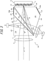
- the electromagnetic wave detection apparatus 100 includes the first image forming unit 15, the progression unit 16, a prism 170, the second image forming unit 18, the first detector 19, and a second detector 20, as illustrated in FIG. 3 . That is, the electromagnetic wave detection apparatus 100 according to the present embodiment is different from the electromagnetic wave detection apparatus 10 according to the first embodiment, in terms of including the prism 170 in place of the prism 17 and including the second detector 20 in addition.
- the prism 170 contain at least a first surface s1, a second surface s20, a third surface s30, a fourth surface s40, a fifth surface s50, and a sixth surface s60.
- a function of the fourth surface s40 is the same as that of the fourth surface s4.
- a function of the sixth surface s60 is the same as that of the sixth surface s6.
- the second surface s20 separates electromagnetic waves progressing in the second direction d2 and into electromagnetic waves to progress in the third direction d3 and electromagnetic waves to progress in the fourth direction d4.
- the prism 170 may separate electromagnetic waves progressing in the second direction d2 into electromagnetic waves to progress in the third direction d3 and electromagnetic waves to progress in the fourth direction d4.
- the second surface s20 may cause electromagnetic waves in a particular wavelength band, from among electromagnetic waves progressing in the second direction d2, to progress in the third direction d3 and cause electromagnetic waves in another wavelength band to progress in the fourth direction d4.
- the second surface s20 may reflect electromagnetic waves in the particular wavelength band, from among electromagnetic waves progressing in the second direction d2, and cause the electromagnetic waves to progress in the third direction d3, and transmit or refract electromagnetic waves in another wavelength band and cause the electromagnetic waves to progress in the fourth direction d4.
- the second surface s20 may totally reflect electromagnetic waves in the particular wavelength band, from among electromagnetic waves progressing in the second direction d2, and cause the electromagnetic waves to progress in the third direction d3, and transmit or refract electromagnetic waves in another wavelength band and cause the electromagnetic waves to progress in the fourth direction d4. That is, the prism 170 may reflect electromagnetic waves in the particular wavelength band and cause the electromagnetic waves to progress in the third direction d3 serving as a third progression direction, and cause electromagnetic waves in another wavelength band to progress in the fourth direction d4 serving as a second progression direction.
- An incident angle of electromagnetic waves progressing in the second direction d2 with respect to the second surface s20 may be smaller than the critical angle.
- the third surface s30 serving as a third emission surface emits electromagnetic waves progressing in the third direction d3. That is, the prism 170 contains the third surface s30 serving as the third emission surface for emitting electromagnetic waves progressing in the third direction d3.
- the third surface s30 may be perpendicular to a progression axis of electromagnetic waves progressing in the third direction d3, that is, perpendicular to the third direction d3.
- the fifth surface s50 causes electromagnetic waves progressing in the fifth direction d5 to progress in the sixth direction d6, in a manner similar to the first embodiment.
- the fifth surface s50 may internally reflect electromagnetic waves progressing in the fifth direction d5 and cause the electromagnetic waves to progress in the sixth direction d6, in a manner similar to the first embodiment.
- the fifth surface s50 may totally internally reflect electromagnetic waves progressing in the fifth direction d5 and cause the electromagnetic waves to progress in the sixth direction d6, in a manner similar to the first embodiment.
- An incident angle of electromagnetic waves progressing in the fifth direction d5 with respect to the fifth surface s50 may be equal to or larger than the critical angle, in a manner similar to the first embodiment.
- the incident angle of electromagnetic waves progressing in the fifth direction d5 with respect to the fifth surface s50 may be different from the incident angle of electromagnetic waves progressing in the second direction d2 with respect to the second surface s20, in a manner similar to the first embodiment.
- the incident angle of electromagnetic waves progressing in the fifth direction d5 with respect to the fifth surface s50 may be larger than the incident angle of electromagnetic waves progressing in the second direction d2 with respect to the second surface s20, in a manner similar to the first embodiment.
- the fifth surface s50 does not need to be parallel to the second surface s20, in a manner different from the first embodiment.
- the prism 170 contains a first prism 210, a second prism 220, a third prism 240, a first intermediate layer 230, and a second intermediate layer 250.
- the first prism 210 may contain a first surface s1, a second surface s20, and a third surface s30 as different surfaces.
- the first prism 210 includes, for example, a triangular prism.
- the first surface s1, the second surface s20, and the third surface s30 may intersect with one another.
- the second prism 220 may contain a fourth surface s40, a fifth surface s50, a sixth surface s60, and a seventh surface s70 as different surfaces.
- the seventh surface s70 may intersect with the fourth surface s40 and the sixth surface s60.
- the second prism 220 may be arranged such that the fourth surface s40 is positioned in a progression direction of electromagnetic waves that progresses within the second prism 220 via the fifth surface s50 after being transmitted through the second surface s20 of the first prism 210, in a manner similar to the first embodiment.
- the second prism 220 may be arranged such that the sixth surface s60 is positioned in the sixth direction d6, which is a reflection angle equal to the incident angle of electromagnetic waves from the fifth direction d5 with respect to the fifth surface s50, in a manner similar to the first embodiment.
- the second prism 220 may be arranged such that an angle b formed by the second direction d2 and the fifth surface s50 is smaller than an angle a formed by the second direction d2 and the second surface s20, in a manner different from the first embodiment.
- the third prism 240 may be arranged between the first intermediate layer 230 and the second intermediate layer 250.
- One slope of the third prism 240 may be in contact with the first intermediate layer 230.
- Another slope of the third prism 240 may be in contact with the second intermediate layer 250.
- the third prism 240 may contain the one slope in contact with the first intermediate layer 230, the another slope in contact with the second intermediate layer 250, and an eighth surface s80 intersecting with the one slope and the another slope, as different surfaces.
- the third prism 240 includes, for example, a triangular prism.
- the first intermediate layer 230 may be arranged between the first prism 210 and the third prism 240.
- the first intermediate layer 230 may be in contact with the second surface s20 of the first prism 210 and may include the second surface s20 along the boundary surface with the first prism 210.
- the first intermediate layer 230 includes, for example, a visible light reflective coating, a half mirror, a beam splitter, a dichroic mirror, a cold mirror, a hot mirror, a meta surface, or a deflecting element, which is attached to the second surface s20.
- the second intermediate layer 250 may be arranged between the second prism 220 and the third prism 240.
- the second intermediate layer 250 may be in contact with the fifth surface s50 of the second prism 220 and may include the fifth surface s50 along the boundary surface with the second prism 220.
- a refractive index of the second intermediate layer 250 may be smaller than that of the second prism 220.
- the second intermediate layer 250 includes, for example, at least one of vacuum, a gas, a liquid, and a solid, which has a refractive index smaller than that of the second prism 220.
- the fifth surface s50 In a configuration in which the incident angle of electromagnetic waves from the fifth direction d5 is equal to or larger than the critical angle, the fifth surface s50 totally internally reflects electromagnetic waves progressing in the fifth direction d5 within the second prism 220 and causes the electromagnetic waves to progress in the sixth direction d6.
- the second intermediate layer 250 In a configuration in which the second intermediate layer 250 is a gas or a liquid, the second intermediate layer 250 may be formed by providing spacers on the respective peripheries of the first another slope of the third prism 240 and the fifth surface s50 of the second prism 220 and filling the spacers with a gas or a liquid.
- the second detector 20 detects electromagnetic waves emitted from the third surface s30.
- the second detector 20 may be provided on a path of electromagnetic waves emitted in the third direction d3 from the prism 170.
- the second detector 20 may be provided at or in the vicinity of the image forming position of the object ob by the first image forming unit 15 in the third direction d3 from the prism 170.
- an image of electromagnetic waves of the object ob that reaches the detection surface of the second detector 20 via the second surface s20 and the third surface s30 may be formed.
- a difference between a length of the progression path of electromagnetic waves progressing in the third direction d3 from the second surface s20 to the second detector 20 and a length of a progression path of electromagnetic waves progressing in the fourth direction d4 from the second surface s20 to the reference surface ss may be equal to or smaller than a predetermined value and, further, may be equal to each other.
- the second detector 20 may be arranged such that the detection surface thereof is parallel to the third surface s30.
- the third surface s30 may be perpendicular to the progression axis of electromagnetic waves progressing in the third direction d3 and emitted.
- the detection surface of the second detector 20 may be perpendicular to a progression axis of electromagnetic waves emitted from the third surface s30.
- the second detector 20 includes a passive sensor.
- the second detector 20 includes, in particular, an element array.
- the second detector 20 may include an image sensor or an imaging array, capture an image of electromagnetic waves formed on the detection surface, and generate image information corresponding to the captured object ob.
- the second detector 20 may capture an image of visible light.
- the second detector 20 may transmit the generated image information to the controller 14.
- the controller 14 acquires information regarding the surroundings of the electromagnetic wave detection apparatus 100, based on the detection result of electromagnetic waves by the second detector 20.
- the second detector 20 may capture an image of infrared light, ultraviolet, radio waves, or the like rather than an image of visible light.
- the second detector 20 may include a distance measuring sensor.
- the electromagnetic wave detection apparatus 100 can acquire distance information in the form of an image using the second detector 20.
- the second detector 20 may include a distance measuring sensor, a temperature sensor, or the like. In this configuration, the electromagnetic wave detection apparatus 100 can acquire temperature information in the form of an image using the second detector 20.
- the second detector 20 may include a sensor of a different type or the same type as that of the first detector 19.
- the second detector 20 may detect electromagnetic waves of a different type or the same type as electromagnetic waves detected by the first detector 19.
- the prism 170 includes a reflection suppressor 900a and a reflection suppressor 900b.
- the reflection suppressor 900a is provided on the seventh surface s70 of the second prism 220.
- the reflection suppressor 900b is provided on the eighth surface s80 of the third prism 240. Electromagnetic waves to be detected by the first detector 19 and the second detector 20 do not reach the seventh surface s70 provided with the reflection suppressor 900a and the eighth surface s80 provided with the reflection suppressor 900b, as illustrated in FIG. 3 . That is, the reflection suppressors 900a and 900b are provided at the respective positions out of the progression paths of the electromagnetic waves to be detected by the first detector 19 and the second detector 20.
- the reflection suppressor 900a is formed by using the seventh surface s70 as the end surface reflection suppression surface.
- the reflection suppressor 900b is formed by using the eighth surface s80 as the end surface reflection suppression surface.
- the electromagnetic wave detection apparatus 100 can suppress end surface reflection on the seventh surface s70 and the eighth surface s80 and reduce unwanted light to be incident on the first detector 19 and the second detector 20.
- FIG. 4 elements having the same configurations as those of each of the embodiments described above are denoted by the same reference signs.
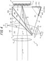
- the electromagnetic wave detection apparatus 101 includes the first image forming unit 15, the progression unit 16, a prism 171, the second image forming unit 18, the first detector. 19, and the second detector 20, as illustrated in FIG. 4 . That is, the electromagnetic wave detection apparatus 101 according to the present embodiment is different from the electromagnetic wave detection apparatus 100 according to the second embodiment, in terms of including the prism 171 in place of the prism 170.
- the configuration and function of the information acquisition system 11 according to the third embodiment other than the electromagnetic wave detection apparatus 101 are the same as those of the second embodiment.
- the prism 171 includes a first prism 210, a second prism 221 a third prism 240, a first intermediate layer 230, and a second intermediate layer 250. That is, the prism 171 of the present embodiment is different from the prism 170 of the second embodiment, in terms of including the second prism 221 in place of the second prism 220.
- the second prism 221 may contain a fourth surface s41, a fifth surface s50, and a sixth surface s61 as different surfaces.
- the second prism 221 includes, for example, a triangular prism.
- the fourth surface s41, the fifth surface s50, and the sixth surface s61 may intersect with one another.
- the function of the fourth surface s41 is the same as that of the fourth surface s40 of the prism 170.
- the function of the sixth surface s61 is the same as that of the sixth surface s60 of the prism 170.
- a configuration of the fourth surface s41 is different from that of the fourth surface s40 of the prism 170.
- a configuration of the sixth surface s61 is different from that of the sixth surface s60 of the prism 170.
- the fourth surface s40 and the seventh surface s70 intersect with each other, and the sixth surface s60 and the seventh surface s70 intersect with each other.
- the fourth surface s41 extends longer than the fourth surface s40 in a direction opposite to a line of intersection of the fourth surface s41 and the fifth surface s50, as illustrated in FIG. 4 .
- the sixth surface s61 extends longer than the sixth surface s60 in a direction opposite to a line of intersection of the sixth surface s61 and the fifth surface s50. Because the fourth surface s41 and the sixth surface s61 extend, the fourth surface s41 and the sixth surface s61 intersect with each other.
- the second prism 221 is expanded by the size of a region 221a and larger than the second prism 220.
- the region 221a is positioned out of progression paths of electromagnetic waves to be detected by the first detector 19 and the second detector 20 after being incident from the first image forming unit 15.
- distances from the region 221a to the progression paths of electromagnetic waves e.g., a progression path of electromagnetic waves progressing in the fifth direction d5 and a progression path of electromagnetic waves progressing in the sixth direction d6 are equal to or longer than a predetermined distance.
- the region 221a functions as a reflection suppressor 901a that suppresses surface reflection light caused by the end surface reflection of the prism 171, which is unnecessary light, from being incident on the first detector 19 and the second detector 20.
- a surface s41a corresponding to the region 221a is provided with the reflection suppressor 901b.
- the reflection suppressor 901b is formed by using the surface s41a as the end surface reflection suppression surface.
- the surface s61a corresponding to the region 221a is provided with a reflection suppressor 901c.
- the reflection suppressor 901c is formed by using the surface s61a as the end surface reflection suppression surface.
- the prism 171 includes the region 221a that functions as the reflection suppressor 901a and is provided at a position out of the progression paths of electromagnetic waves to be detected by the first detector 19 and the second detector 20 after being incident from the first image forming unit 15.
- the region 221a is positioned at a distance equal to or longer than the predetermined distance from the progression paths of electromagnetic waves to be detected by the first detector 19 and the second detector 20.
- the electromagnetic wave detection apparatus 101 can reduce unnecessary light to be incident on the first detector 19 and the second detector 20.
- FIG. 5 elements having the same configurations as those of each of the embodiments described above are denoted by the same reference signs.
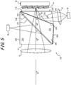
- the electromagnetic wave detection apparatus 102 includes the first image forming unit 15, the progression unit 16, a prism 172, the second image forming unit 18, the first detector 19, and the second detector 20, as illustrated in FIG. 5 . That is, the electromagnetic wave detection apparatus 102 according to the present embodiment is different from the electromagnetic wave detection apparatus 100 according to the second embodiment, in terms of including the prism 172 in place of the prism 170.
- the configuration and function of the information acquisition system 11 according to the present embodiment other than the electromagnetic wave detection apparatus 102 are the same as those of the second embodiment.
- the prism 172 contain at least a first surface s1, a second surface s20, a third surface s30, a fourth surface s40, a fifth surface s50, and a sixth surface s60.
- the configurations and functions of these surfaces are the same as those of the second embodiment.
- the prism 172 includes a first prism 210, a second prism 222, a third prism 242, a first intermediate layer 230, and a second intermediate layer 250.
- the second prism 222 may contain a fourth surface s40, a fifth surface s50, and a sixth surface s60 as different surfaces.
- the second prism 222 includes, for example, a triangular prism.
- the fourth surface s40, the fifth surface s50, and the sixth surface s60 may intersect with each other.
- the second prism 222 may be arranged such that the fourth surface s40 is positioned in a progression direction of electromagnetic waves progressing within the second prism 222 via the fifth surface s50 after being transmitted through the second surface s20 of the first prism 210, in a manner similar to the second embodiment.
- the second prism may be arranged such that the sixth surface s60 is arranged in the sixth direction d6, which is a reflection angle equal to the incident angle of electromagnetic waves from the fifth direction d5 with respect to the fifth surface s50, in a manner similar to the first embodiment.
- the second prism 222 may arranged such that an angle b formed by the second direction d2 and the fifth surface s50 is larger than an angle a formed by the second direction d2 and the second surface s20, in a manner different from the second embodiment.
- the third prism 242 may be arranged between the first intermediate layer 230 and the second intermediate layer 250. One slope of the third prism 242 may be in contact with the first intermediate layer 230. Another slope of the third prism 242 may be in contact with the second intermediate layer 250. The third prism 242 may contain the one slope in contact with the first intermediate layer 230, the another slope in contact with the second intermediate layer 250, and an eighth surface s82 intersecting with the one slope and the another slope, as different surfaces.
- the third prism 242 includes, for example, a triangular prism.
- the prism 172 includes a reflection suppressor 902.
- the reflection suppressor 902 is provided on the eighth surface s82 of the third prism 242. Electromagnetic waves to be detected by the first detector 19 and the second detector 20 do not reach the eighth surface s82 provided with the reflection suppressor 902, as illustrated in FIG. 5 .
- the reflection suppressor 902 is provided at a position out of progression paths of electromagnetic waves to be detected by the first detector 19 and the second detector 20.
- the reflection suppressor 902 is formed by using the eighth surface s82 as the end surface reflection suppression surface. By using the eighth surface s82 as the end surface reflection suppression surface, end surface reflection on the eighth surface s82 can be suppressed.
- the electromagnetic wave detection apparatus 102 according to the present embodiment can suppress end surface reflection on the eighth surface s82 and reduce unnecessary light to be incident on the first detector 19 and the second detector 20.
- FIG. 6 elements having the same configurations as those of each of the embodiments described above are denoted by the same reference signs.
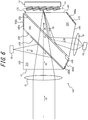
- the electromagnetic wave detection apparatus 103 includes the first image forming unit 15, the progression unit 16, a prism 173, the second image forming unit 18, the first detector 19, and the second detector 20, as illustrated in FIG. 6 . That is, the electromagnetic wave detection apparatus 103 according to the present embodiment is different from the electromagnetic wave detection apparatus 100 according to the second embodiment, in terms of including the prism 173 in place of the prism 170. In the information acquisition system 11 according to the fifth embodiment, the configurations and functions other than the electromagnetic wave detection apparatus 103 are the same as those of the second embodiment.
- the prism 173 contain at least a first surface s1, a second surface s20, a third surface s30, a fourth surface s40, a fifth surface s50, and a sixth surface s60.
- the configurations and functions of these surfaces are the same as those of the second embodiment.
- the prism 173 includes a first prism 210, a second prism 223, a third prism 243, a first intermediate layer 230, and a second intermediate layer 250.
- the second prism 223 may contain the fourth surface s40, the fifth surface s50, the sixth surface s60, and a seventh surface s70 as different surfaces.
- the seventh surface s70 may intersect with the fourth surface s40 and the sixth surface s60.
- the seventh surface s70 is provided with a reflection suppressor 900a, in a manner similar to the second embodiment.
- the second prism 223 may be arranged in a manner similar to the second embodiment such that the fourth surface s40 is positioned in a progression direction of electromagnetic waves that progress within the second prism 220 via the fifth surface s50 after being transmitted through the second surface s20 of the first prism 210.
- the second prism 223 may be arranged in a manner similar to the second embodiment such that the sixth surface s60 is arranged in the sixth direction d6, which is a reflection angle equal to the incident angle of electromagnetic waves from the fifth direction d5 with respect to the fifth surface s50.
- the second prism 223 may be arranged in a manner different from the second embodiment such that an angle a formed by the second direction d2 and the second surface s20 and an angle b formed by the second direction d2 and the fifth surface s50 are equal to each other.
- a third prism 243 may be arranged between the first intermediate layer 230 and the second intermediate layer 250.
- the third prism 243 may contain a plate-like shape.
- One plate surface of the third prism 243 may be in contact with the first intermediate layer 230.
- the other plate surface of the third prism 243 may be in contact with the second intermediate layer 250.
- the third prism 243 may contain an eighth surface s83a that intersects with one end of the one plate surface and one end of the other plate surface, and an eighth surface s83b that intersects with the other end of the one plate surface and the other end of the other plate surface.
- the prism 173 includes a reflection suppressor 903a and a reflection suppressor 903b, in addition to the reflection suppressor 900a.
- the reflection suppressor 903a is provided on the eighth surface s83a of the third prism 243.
- the reflection suppressor 903b is provided on the eighth surface s83b of the third prism 243. Electromagnetic waves to be detected by the first detector 19 and the second detector 20 do not reach the eight surface s83a provided with the reflection suppressor 903a and the eighth surface s83b provided with the reflection suppressor 903b, as illustrated in FIG. 6 .
- the reflection suppressors 903a and 903b are provided at positions out of progression paths of electromagnetic waves to be detected by the first detector 19 and the second detector 20.
- the reflection suppressor 903a is formed by using the eighth surface s83a as an end surface reflection suppression surface.
- the reflection suppressor 903b is formed by using the eighth surface 83b as an end surface reflection suppression surface.
- the eighth surface s83a and the eighth surface s83b as the end surface reflection suppression surfaces, end surface reflection on these surfaces can be suppressed. Accordingly, the electromagnetic wave detection apparatus 103 according to the present embodiment can suppress end surface reflection on the eighth surface s83a and the eighth surface s83b and reduce unwanted light to be incident on the first detector 19 and the second detector 20.
- FIG. 7 elements having the same configurations as those of the embodiments described above are denoted by the same reference signs.
- the electromagnetic wave detection apparatus 104 includes the first image forming unit 15, the progression unit 16, a prism 174, the second image forming unit 18, the first detector 19, and the second detector 20, as illustrated in FIG. 7 . That is, the electromagnetic wave detection apparatus 104 according to the present embodiment is different from the electromagnetic wave detection apparatus 100 according to the second embodiment, in terms of including the prism 174 in place of the prism 170.
- the configuration and function of the information acquisition system 11 according to the present embodiment other than the electromagnetic wave detection apparatus 104 are the same as those of the second embodiment.
- the prism 174 includes a first prism 210, a second prism 224, a third prism 243, a first intermediate layer 230, and a second intermediate layer 250.
- the second prism 224 may contain a fourth surface s44, a fifth surface s50, and a sixth surface s64 as different surfaces.
- the second prism 224 includes, for example, a triangular prism.
- the fourth surface s44, the fifth surface s50, and the sixth surface s64 may intersect with one another.
- the function of the fourth surface s44 is the same as that of the fourth surface s40 of the prism 173.
- the function of the sixth surface s64 is the same as that of the sixth surface s60 of the prism 173.
- the configuration of the fourth surface s44 is different from the configuration of the fourth surface s40 of the prism 173.
- the configuration of the sixth surface s64 is different from the configuration of the sixth surface s60 of the prism 173.
- the fourth surface s40 and a seventh surface s70 intersect with each other, and the sixth surface s60 and the seventh surface s70 intersect with each other.
- the fourth surface s44 extends longer than the fourth surface s40 in a direction opposite to a line of intersection of the fourth surface s44 and the fifth surface s50, as illustrated in FIG. 7 .
- the sixth surface s64 extends longer than the sixth surface s60 in a direction opposite to a line of intersection of the sixth surface s64 and the fifth surface s50. Because the fourth surface s44 and the sixth surface s64 extend, the fourth surface s44 and the sixth surface s64 intersect with each other.
- the second prism 224 is expanded by the size of the region 224a and larger than the second prism 223.
- the region 224a is positioned out of a progression path of electromagnetic waves incident from the first image forming unit 15 and to be detected by the first detector 19 and the second detector 20. Further, distances to the region 224a from, for example, a progression path of electromagnetic waves progressing in the fifth direction d5 and a progression path of electromagnetic waves progressing in the sixth direction d6 are equal to or longer than a predetermined distance.
- the region 224a functions as a reflection suppressor 904a that suppresses surface reflection light caused by end surface reflection of the prism 174, which is unnecessary light, from being incident on the first detector 19 and the second detector 20.
- the surface s44a corresponding to the region 224a is provided with a reflection suppressor 904b.
- the reflection suppressor 904b is formed by using the surface s44a as the end surface reflection suppression surface.
- the surface s64a corresponding to the region 224a is provided with a reflection suppressor 904c.
- the reflection suppressor 904c is formed by using the surface s64a as the end surface reflection suppression surface.
- the prism 174 is arranged at a position out of the progression paths of electromagnetic waves to be detected by the first detector 19 and the second detector 20 after being incident from the first image forming unit 15, and includes the region 224a that functions as the reflection suppressor 904a.
- distances to the region 224a from the progression paths of electromagnetic waves to be detected by the first detector 19 and the second detector 20 are equal to or longer than the predetermined distance.
- This configuration suppresses surface reflection light that occurs in the region 224a of the prism 174 from being incident on the first detector 19 and the second detector 20. Accordingly, the electromagnetic wave detection apparatus 104 according to the present embodiment can reduce unnecessary light to be incident on the first detector 19 and the second detector 20.
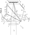
- FIG. 8 elements having the same configurations as those of each of the embodiments described above are denoted by the same reference signs.
- the electromagnetic wave detection apparatus 105 includes the first image forming unit 15, the progression unit 16, a prism 175, the second image forming unit 18, the first detector 19, and the second detector 20, as illustrated in FIG. 8 . That is, the electromagnetic wave detection apparatus 105 according to the present embodiment is different from the electromagnetic wave detection apparatus 100 according to the second embodiment, in terms of including the prism 175 in place of the prism 170.
- the configuration and function of the information acquisition system 11 according to the present embodiment other than the electromagnetic wave detection apparatus 105 are the same as those of the second embodiment.
- the prism 175 contains at least a first surface s15, a second surface s25, a third surface s35, a fourth surface s45, a fifth surface s55, and a sixth surface s65.
- the first surface s15 causes electromagnetic waves incident on the prism 175 from the first direction d1 to progress in the second direction d2.
- the first surface s15 may be perpendicular to a progression axis of electromagnetic waves incident on the first surface s15 from the first direction d1. Because the first direction d1 is parallel to the principal axis of the first image forming unit 15 as described above, the principal axis of the first image forming unit 15 and the first surface s15 may be perpendicular to each other, in other words, the principal plane of the image forming unit 15 and the first surface s15 may be parallel to each other.
- the first surface s15 may transmit or refract electromagnetic waves incident from the first direction d1 and cause the electromagnetic waves to progress in the second direction d2.
- the first surface s15 causes electromagnetic waves progressing in the third direction d3 to progress in a seventh direction d7, as will be described later.
- the first surface s15 may internally reflect electromagnetic waves progressing in the third direction d3 and cause the electromagnetic waves to progress in the seventh direction d7.
- the first surface s15 may totally internally reflect electromagnetic waves progressing in the third direction d3 and cause the electromagnetic waves to progress in the seventh direction d7.
- An incident angle of electromagnetic waves progressing in the third direction d3 with respect to the first surface s15 may be equal to or larger than the critical angle.
- the second surface s25 separates electromagnetic waves progressing in the second direction d2 into electromagnetic waves to progress in the third direction d3 and electromagnetic waves to progress in the fourth direction d4.
- the second surface s25 may cause electromagnetic waves in a particular wavelength band, from among electromagnetic waves progressing in the second direction d2, to progress in the third direction d3 and cause electromagnetic waves in another wavelength band to progress in the fourth direction d4.
- the second surface s25 may reflect electromagnetic waves in the particular wavelength band, from among electromagnetic waves progressing in the second direction d2, and causes the electromagnetic waves to progress in the third direction d3, and transmit or refract electromagnetic waves in another particular wavelength band to progress in the fourth direction d4.
- the second surface s25 may totally reflect electromagnetic waves in the particular wavelength band, from among electromagnetic waves progressing in the second direction d2, and cause the electromagnetic waves to progress in the third direction d3, and transmit or refract electromagnetic waves in another wavelength band and cause the electromagnetic waves to progress in the fourth direction d4.
- An incident angle of electromagnetic waves progressing in the second direction d2 with respect to the second surface s25 may be smaller than the critical angle.
- the third surface s35 serving as the third emission surface emits electromagnetic waves having progressed in the seventh direction d7.
- the third surface s35 may be perpendicular to a progression axis of electromagnetic waves progressing in the seventh direction d7, that is, perpendicular to the seventh direction d7. Electromagnetic waves emitted from the third surface s35 are detected by the second detector 20.
- the fourth surface s45 serving as the first emission surface emits electromagnetic waves having progressed in the fourth direction d4 to the reference surface ss of the progression unit 16. Further, the fourth surface s45 causes electromagnetic wave re-incident from the reference surface ss of the progression unit 16 to progress in the fifth direction d5.
- the fourth surface s45 may be perpendicular to the progression axis of electromagnetic wave progressing in the fourth direction d4, that is, perpendicular to the fourth direction d4.
- the fourth surface s45 may be parallel to the reference surface ss of the progression unit 16.
- the fourth surface s45 may transmit or refract electromagnetic waves re-incident from the reference surface ss and cause the electromagnetic waves to progress in the fifth direction d5.
- the fifth surface s55 causes electromagnetic waves progressing in the fifth direction d5 to progress in the sixth direction d6.
- the fifth surface s55 may internally reflect electromagnetic waves progressing in the fifth direction d5 and cause the electromagnetic waves to progress in the sixth direction d6.
- the fifth surface s55 may totally internally reflect electromagnetic waves progressing in the fifth direction d5 and cause the electromagnetic waves to progress in the sixth direction d6.
- An incident angle of electromagnetic waves progressing in the fifth direction d5 with respect to the fifth surface s55 may be equal to or larger than the critical angle.
- the incident angle of electromagnetic waves progressing in the fifth direction d5 with respect to the fifth surface s55 may be different from the incident angle of electromagnetic waves progressing in the second direction d2 with respect to the second surface s25.
- the incident angle of electromagnetic waves progressing in the fifth direction d5 with respect to the fifth surface s55 may be larger than the incident angle of electromagnetic waves progressing in the second direction d2 with respect to the second surface s25.
- the fifth surface s55 does not need to be parallel to the second surface s25.
- the sixth surface s65 serving as the second emission surface emits electromagnetic waves progressing in the sixth direction d6.
- the sixth surface s65 may be perpendicular to a progression axis of electromagnetic waves progressing in the sixth direction d6, that is, perpendicular to the sixth direction d6.
- the prism 175 contains a first prism 215, a second prism 225, a third prism 245, a first intermediate layer 230, and a second intermediate layer 250.
- the first prism 215 may contain a first surface s15, a second surface s25, and a third surface s35 as different surfaces.
- the first prism 215 includes, for example, a triangular prism.
- the first surface s15, the second surface s25, and the third surface s35 may intersect with one another.
- the first prism 215 may be arranged such that a progression axis of electromagnetic waves incident on the first surface s15 from the first direction d1 and the first surface s15 are perpendicular to each other.
- the first prism 215 may be arranged such that the second surface s25 is positioned in a progression direction of electromagnetic waves that progress within the first prism 215 after being transmitted through or refracted by the first surface s15 from the first direction d1.
- the first prism 215 may be arranged such that the first surface s15 is positioned in a progression direction of electromagnetic waves after being reflected on the second surface s25.
- the first prism 215 may be arranged such that the third surface s35 is positioned in a progression direction of electromagnetic waves reflected on the first surface s15 after progressing in the third direction d3.
- the second prism 225 may contain a fourth surface s45, a fifth surface s55, a sixth surface s65, and a seventh surface s75 as different surfaces.
- the seventh surface s75 may intersect with the fourth surface s45 and the sixth surface s65.
- the second prism 225 may be arranged such that the fourth surface s45 is positioned in a progression direction of electromagnetic waves that progress within the second prism 225 via the fifth surface s55 after being transmitted through the second surface s25 of the first prism 215.
- the second prism 225 may be arranged such that the sixth surface s65 is positioned in the sixth direction, which is a reflection angle equal to an incident angle of electromagnetic waves from the fifth direction d5 with respect to the fifth surface s55.
- the second prism 225 may be arranged such that an angle b formed by the second direction d2 and the fifth surface s55 is smaller than an angle a formed by the second direction d2 and the second surface s25.
- the third prism 245 may be arranged between the first intermediate layer 230 and the second intermediate layer 250. One slope of the third prism 245 may be in contact with the first intermediate layer 230. Another slope of the third prism 245 may be in contact with the second intermediate layer 250.
- the third prism 240 may contain the one slope in contact with the first intermediate layer 230, the another slope in contact with the second intermediate layer 250, and an eighth surface s85 intersecting with the one slope and the another slope, as different surfaces.
- the third prism 245 includes, for example, a triangular prism.
- the first intermediate layer 230 may be arranged between the first prism 215 and the third prism 245.
- the first intermediate layer 230 may be in contact with the second surface s25 of the first prism 215 and may include the second surface s25 along the boundary surface with the first prism 215.
- the second intermediate layer 250 may be arranged between the second prism 225 and the third prism 245.
- the second intermediate layer 250 may be in contact with the fifth surface s55 of the second prism 225 and may include the fifth surface s55 along the boundary surface with the second prism 225.
- the refractive index of the second intermediate layer 250 may be smaller than that of the second prism 225.
- the fifth surface s55 In a configuration in which the incident angle of electromagnetic waves from the fifth direction d5 is equal to or larger than the critical angle, the fifth surface s55 totally internally reflects electromagnetic waves progressing in the fifth direction d5 within the second prism 225 and causes the electromagnetic waves to progress in the sixth direction d6.
- the prism 175 includes a reflection suppressor 905a and a reflection suppressor 905b.
- the reflection suppressor 905a is provided on the seventh surface s75 of the second prism 225.
- the reflection suppressor 905b is provided on the eighth surface s85 of the third prism 245. Electromagnetic waves to be detected by the first detector 19 and the second detector 20 do not reach the seventh surface s75 provided with the reflection suppressor 905a and the eighth surface s85 provided with the reflection suppressor 905b, as illustrated in FIG. 8 .
- the reflection suppressors 905a and 905b are provided at the respective positions out of progression paths of electromagnetic waves to be detected by the first detector 19 and the second detector 20.
- the reflection suppressor 905a is formed by using the seventh surface s75 as the end surface reflection suppression surface.
- the reflection suppressor 905b is formed by using the eighth surface s85 as the end surface reflection suppression surface.
- the electromagnetic wave detection apparatus 105 can suppress end surface reflection on the seventh surface s75 and the eighth surface s85 and reduce unwanted light to be incident on the first detector 19 and the second detector 20.
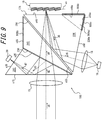
- FIG. 9 elements having the same configurations as those of each of the embodiments described above are denoted by the same reference signs.
- the electromagnetic wave detection apparatus 106 includes the first image forming unit 15, the progression unit 16, a prism 176, the second image forming unit 18, the first detector 19, and the second detector 20, as illustrated in FIG. 9 .
- the electromagnetic wave detection apparatus 106 according to the present embodiment is different from the electromagnetic wave detection apparatus 105 according to the seventh embodiment, in terms of including the prism 176 in place of the prism 175.
- the configuration and function of the information acquisition system 11 according to the present embodiment other than the electromagnetic wave detection apparatus 106 are the same as those of the seventh embodiment.
- the prism 176 includes a first prism 215, a second prism 226, a third prism 245, a first intermediate layer 230, and a second intermediate layer 250.
- the second prism 226 may contain a fourth surface s46, a fifth surface s55, and a sixth surface s66 as different surfaces.
- the second prism 226 includes, for example, a triangular prism.
- the fourth surface s46, the fifth surface s55, and the sixth surface s66 may intersect with one another.
- the function of the fourth surface s46 is the same as that of the fourth surface s45 of the prism 175.
- the function of the sixth surface s66 is the same as that of the sixth surface s65 of the prism 175.
- a configuration of the fourth surface s46 is different from that of the fourth surface s45 of the prism 175.
- a configuration of the sixth surface s66 is different from that of the sixth surface s65 of the prism 175.
- the fourth surface s45 and the seventh surface s75 intersect with each other, and the sixth surface s65 and the seventh surface s75 intersect with each other.
- the fourth surface s46 extends longer than the fourth surface s45 in a direction opposite to a line of intersection of the fourth surface s46 and the fifth surface s55, as illustrated in FIG. 9 .
- the sixth surface s66 extends longer than the sixth surface s65 in a direction opposite to a line of intersection of the sixth surface s66 and the fifth surface s55. Because the fourth surface s46 and the sixth surface s66 extend, the fourth surface s46 and the sixth surface s66 intersect with each other.
- the second prism 226 is expanded by the size of the region 226a and larger than the second prism 225.
- the region 226a is positioned out of the progression paths of electromagnetic waves to be detected by the first detector 19 and the second detector 20 after being incident from the first image forming unit 15, as illustrated in FIG. 9 . Further, distances to the region 226a from the progression paths of electromagnetic waves, e.g., the progression path of electromagnetic waves progressing in the fifth direction d5 and the progression path of electromagnetic waves progressing in the sixth direction d6 are equal to or longer than a predetermined distance.
- the region 226a functions as a reflection suppressor 906a that suppresses surface reflection light caused by end surface reflection of the prism 176, which is unnecessary light, from being incident on the first detector 19 and the second detector 20.
- the surface s46a corresponding to the region 226a is provided with a reflection suppressor 906b.
- the reflection suppressor 906b is formed by using the surface s46a as the end surface reflection suppression surface.
- the surface s66a corresponding to the region 226a is provided with a reflection suppressor 906c.
- the reflection suppressor 906c is formed by using the surface s66a as the end surface reflection suppression surface.
- the prism 176 includes the region 226a serving as the reflection suppressor 906a that is arranged at a position out of the progression paths of electromagnetic waves to be detected by the first detector 19 and the second detector 20 after being incident from the first image forming unit 15.
- the distances to the region 226a from the progression paths of electromagnetic waves to be detected by the first detector 19 and the second detector 20 are equal to or longer than the predetermined distance. In this configuration, even if end surface reflection occurs in the region 226a of the prism 176, surface reflection light is suppressed from being incident on the first detector 19 and the second detector 20. Accordingly, the electromagnetic wave detection apparatus 106 according to the present embodiment can reduce unnecessary light to be incident on the first detector 19 and the second detector 20.
- FIG. 10 elements having the same configurations as those of each of the embodiments described above are denoted by the same reference signs.
- the electromagnetic wave detection apparatus 107 includes the first image forming unit 15, the progression unit 16, a prism 177, the second image forming unit 18, the first detector 19, and the second detector 20, as illustrated in FIG. 10 .
- the electromagnetic wave detection apparatus 107 according to the present embodiment is different from the electromagnetic wave detection apparatus 105 according to the seventh embodiment, in terms of including the prism 177 in place of the prism 175.
- the configuration and function of the information acquisition system 11 according to the present embodiment other than the electromagnetic wave detection apparatus 107 are the same as those of the seventh embodiment.
- the prism 175 contains at least a first surface s15, a second surface s25, a third surface s35, a fourth surface s45, a fifth surface s55, and a sixth surface s65.
- the configuration and function of these surfaces are the same as those of the seventh embodiment.
- the prism 177 includes a first prism 215, a second prism 227, a third prism 247, a first intermediate layer 230, and a second intermediate layer 250.
- the second prism 227 may contain a fourth surface s45, a fifth surface s55, and a sixth surface s65 as different surfaces.
- the second prism 227 includes, for example, a triangular prism.
- the fourth surface s45, the fifth surface s55, and the sixth surface s65 may intersect with one another.
- the second prism 227 may be arranged in the same manner as the seventh embodiment such that the fourth surface s45 is positioned in the progression direction of electromagnetic waves that progress within the second prism 227 via the fifth surface s55 after being transmitted through the second surface s25 of the first prism 215.
- the second prism 227 may be arranged in the same manner as the seventh embodiment such that the sixth surface s65 is positioned in the sixth direction d6, which is the reflection angle equal to the incident angle of electromagnetic waves from the fifth direction d5 with respect to the fifth surface s55.
- the second prism 227 may be arranged in a manner different from the seventh embodiment such that an angle b formed by the second direction d2 and the fifth surface s55 is larger than an angle a formed by the second direction d2 and the second surface s25.
- the third prism 247 may be arranged between the first intermediate layer 230 and the second intermediate layer 250.
- the third prism 247 may contain a plate-like shape.
- One plate surface of the third prism 247 may be in contact with the first intermediate layer 230.
- the other plate surface of the third prism 247 may be in contact with the second intermediate layer 250.
- the third prism 247 may include an eighth surface s87a that intersects with one end of the one plate surface of the third prism 247 and one end of the other plate surface and an eighth surface s87b that intersects with the other end of the one plate surface of the third prism 247 and the other end of the other plate surface.
- the prism 177 includes a reflection suppressor 907a and a reflection suppressor 907b.
- the reflection suppressor 907a is provided on the eighth surface s87a of the third prism 247.
- the reflection suppressor 907b is provided on the eighth surface s87b of the third prism 247. Electromagnetic waves to be detected by the first detector 19 and the second detector 20 do not reach the eighth surface s87a provided with the reflection suppressor 907a and the eighth surface s87b provided with the reflection suppressor 907b, as illustrated in FIG. 10 .
- the reflection suppressors 907a and 907b are provided at positions out of the progression paths of the electromagnetic waves to be detected by the first detector 19 and the second detector 20.
- the reflection suppressor 907a is formed by using the eighth surface s87a as the end surface reflection suppression surface.
- the reflection suppressor 907b is formed by using the eighth surface s87b as the end surface reflection suppression surface.
- the eighth surface s87a and the eighth surface s87b as the end surface reflection suppression surfaces, end surface reflection on these surfaces can be suppressed. Accordingly, the electromagnetic wave detection apparatus 107 according to the present embodiment can suppress end surface reflection on the eighth surface s87a and the eighth surface s87b and reduce unwanted light to be incident on the first detector 19 and the second detector 20.
- FIG. 11 elements having the same configurations as those of each of the embodiments described above are denoted by the same reference signs.
- the electromagnetic wave detection apparatus 108 includes the first image forming unit 15, the progression unit 16, a prism 178, the second image forming unit 18, the first detector 19, and the second detector 20, as illustrated in FIG. 11 .
- the electromagnetic wave detection apparatus 108 according to the present embodiment is different from the electromagnetic wave detection apparatus 107 according to the ninth embodiment, in terms of including the prism 178 in place of the prism 177.
- the configuration and function of the information acquisition system 11 according to the present embodiment other than the electromagnetic wave detection apparatus 108 are the same as those of the ninth embodiment.
- the prism 178 contains at least a first surface s15, a second surface s25, a third surface s35, a fourth surface s45, a fifth surface s55, and a sixth surface s65.
- the configuration and function of these surfaces are the same as those of the ninth embodiment.
- the prism 178 includes a first prism 215, a second prism 228, a third prism 248, a first intermediate layer 230, and a second intermediate layer 250.
- the second prism 228 may contain the fourth surface s45, the fifth surface s55, and the sixth surface s65 as different surfaces.
- the second prism 228 includes, for example, a triangular prism.
- the fourth surface s45, the fifth surface s55, and the sixth surface s65 may intersect with one another.
- the second prism 228 may be arranged in the same manner as the ninth embodiment such that the fourth surface s45 is positioned in the progression direction of electromagnetic waves progressing within the second prism 228 via the fifth surface s55 after being transmitted through the second surface s25 of the first prism 215.
- the second prism 228 may be arranged in the same manner as the ninth embodiment such that the sixth surface s65 is positioned in the sixth direction d6, which is the reflection angle equal to the incident angle of electromagnetic waves from the fifth direction d5 with respect to the fifth surface s55.
- the second prism 228 may be arranged in a manner different from the ninth embodiment such that an angle a formed by the second direction d2 and the second surface s25 and an angle b formed by the second direction d2 and the fifth surface s55 are equal to each other.
- the third prism 248 may be arranged between the first intermediate layer 230 and the second intermediate layer 250.
- the third prism 248 may contain a plate-like shape.
- One plate surface of the third prism 248 may be in contact with the first intermediate layer 230.
- the other plate surface of the third prism 248 may be in contact with the second intermediate layer 250.
- the third prism 248 may include an eight surface s88a that intersects with one end of the one plate surface and one end of the other plate surface, and an eight surface s88b that intersects with the other end of one plate surface and the other end of the other plate surface.
- the prism 178 includes a reflection suppressor 908a and a reflection suppressor 908b.
- the reflection suppressor 908a is provided on the eighth surface s88a of the third prism 248.
- the reflection suppressor 908b is provided on the eighth surface s88b of the third prism 248.
- electromagnetic waves to be detected by the first detector 19 and the second detector 20 do not reach the eighth surface s88a provided with the reflection suppressor 908a and the eighth surface s88b provided with the reflection suppressor 908b.
- the reflection suppressors 908a and 908b are provided at positions out of the progression paths of electromagnetic waves to be detected by the first detector 19 and the second detector 20.
- the reflection suppressor 908a is formed by using the eighth surface s88a as the end surface reflection suppression surface.
- the reflection suppressor 908b is formed by using the eighth surface s88b as the end surface reflection suppression surface.
- the eighth surface s88a and the eighth surface s88b as the end surface reflection suppression surfaces, end surface reflection on these surfaces can be suppressed. Accordingly, the electromagnetic wave detection apparatus 108 according to the present embodiment can reduce unnecessary light to be incident on the first detector 19 and the second detector 20.
- FIG. 12 elements having the same configurations as those of each of the embodiments described above are denoted by the same reference signs.
- the electromagnetic wave detection apparatus 109 includes the first image forming unit 15, the progression unit 16, a prism 179, the second image forming unit 18, the first detector 19, and the second detector 20, as illustrated in FIG. 12 .
- the electromagnetic wave detection apparatus 109 according to the present embodiment is different from the electromagnetic wave detection apparatus 107 according to the seventh embodiment, in terms of including the prism 179 in place of the prism 177.
- the configuration and function of the information acquisition system 11 according to the present embodiment other than the electromagnetic wave detection apparatus 109 are the same as those of the seventh embodiment.
- the prism 179 contains at least a first surface s15, a second surface s25, a third surface s35, a fourth surface s45, a fifth surface s59, and a sixth surface s69.
- the configurations and functions of the first surface s15, the second surface s25, the third surface s35, and the fourth surface s45 are the same as those of the seventh embodiment.
- the fifth surface s59 causes electromagnetic waves progressing in the fifth direction d5 to progress in the sixth direction d6.
- the fifth surface s59 may internally reflect electromagnetic waves progressing in the fifth direction d5 and cause the electromagnetic waves to progress in the sixth direction d6.
- the fifth surface s59 may totally internally reflect electromagnetic waves progressing in the fifth direction d5 and cause the electromagnetic waves to progress in the sixth direction d6.
- An incident angle of electromagnetic waves progressing in the fifth direction d5 with respect to the fifth surface s59 may be equal to or larger than the critical angle.
- the incident angle of electromagnetic waves progressing in the fifth direction d5 with respect to the fifth surface s59 may be different from the incident angle of electromagnetic waves progressing in the second direction d2 with respect to the second surface s25.
- the incident angle of electromagnetic waves progressing in the fifth direction d5 with respect to the fifth surface s59 may be larger than the incident angle of electromagnetic waves progressing in the second direction d2 with respect to the second surface s25.
- the fifth surface s59 may be parallel to the second surface s25.
- the sixth surface s69 emits electromagnetic waves progressing in the sixth direction d6.
- the sixth surface s69 may be perpendicular to the progression axis of electromagnetic waves progressing in the sixth direction d6, that is, perpendicular to the sixth direction d6.
- electromagnetic waves progressing in the sixth direction d6 is emitted from a portion of the sixth surface s69 closer to the line of intersection of the sixth surface s69 and the fifth surface s59 than the line of intersection of the sixth surface s69 with the fourth surface s45.
- the sixth surface s69 includes a surface s69a that extends from the line of intersection of the sixth surface s69 and the fourth surface s45 and is positioned out of the progression path of electromagnetic waves to be detected by the first detector 19.
- the prism 179 includes a first prism 215, a second prism 229, a first intermediate layer 230, and a second intermediate layer 259.
- the second prism 229 may have the fourth surface s45, the fifth surface s59, the sixth surface s69, and a ninth surface s99 as different surfaces.
- the ninth surface 99 may intersect with the fourth surface s45 and the fifth surface s59.
- the second prism 229 may be arranged such that the fifth surface s59 is parallel to and opposes the second surface s25 of the first prism 215.
- the second prism 229 may be arranged such that the fourth surface s45 is positioned in a progression direction of electromagnetic waves progressing within the second prism 229 via the fifth surface s59 after being transmitted through the second surface s25 of the first prism 215.
- the second prism 229 may be arranged such that the sixth surface s69 is positioned in the sixth direction d6, which is a reflection angle equal to the incident angle of electromagnetic waves from the fifth direction d5 with respect to the fifth surface s59.
- the second intermediate layer 259 may be arranged between the fifth surface s59 of the second prism 229 and the first intermediate layer 230.
- the second intermediate layer 259 may by in contact with the fifth surface s59 of the second prism 229 and may include the fifth surface s59 along the boundary surface with the second prism 229.
- the second intermediate layer 259 may be in contact with the surface of the first intermediate layer 230 on an opposite side from a contact surface of the first intermediate layer 230 in contact with the first prism 215.
- the second intermediate layer 259 may have a refractive index smaller than that of the second prism 229.
- the second intermediate layer 259 includes, for example, at least one of vacuum, a gas, a liquid, and a solid, which has a refractive index smaller than that of the second prism 229.
- electromagnetic waves progressing within the second prism 229 and incident at an incident angle equal to or larger than the critical angle are totally internally reflected on the fifth surface s59.
- the fifth surface s59 internally reflects electromagnetic waves progressing within the second prism 229 in the fifth direction d5 serving as the progression axis.
- the fifth surface s59 In a configuration in which the incident angle of electromagnetic waves from the fifth direction d5 is equal to or larger than the critical angle, the fifth surface s59 totally internally reflects electromagnetic waves progressing in the fifth direction d5 and causes the electromagnetic waves to progress in the sixth direction d6.
- the prism 179 includes a reflection suppressor 909a and a reflection suppressor 909b.
- the reflection suppressor 909a is provided on the ninth surface s99 of the second prism 229.
- the reflection suppressor 909b is provided on the surface s69a of the second prism 229.
- electromagnetic waves to be detected by the first detector 19 and the second detector 20 do not reach the surface s99a provided with the reflection suppressor 909a and the surface s69a provided with the reflection suppressor 909b.
- the reflection suppressors 909a and 909b are arranged at positions out of the progression paths of electromagnetic waves to be detected by the first detector 19 and the second detector 20.
- the reflection suppressor 909a is formed by using the ninth surface s99 as the end surface reflection suppression surface.
- the reflection suppressor 909b is formed by using the surface s69a as the end surface reflection suppression surface.
- the radiation unit 12, the scanner 13, and the controller 14 constitute the information acquisition system 11, together with the electromagnetic wave detection apparatus 10, 100, 101, 102, 103, 104, 105, 106, 107, 108, or 109.
- the electromagnetic wave detection apparatus 10, 100, 101, 102, 103, 104, 105, 106, 107, 108, and 109 may be configured including at least one of them.
- the electromagnetic wave detection apparatus 10 may include the radiation unit 12, the scanner 13, and the controller 14, as illustrated in FIG. 13 .
- the electromagnetic wave detection apparatus 100, 101, 102, 103, 104, 105, 106, 107, 108, and 109 according to the second to eleventh embodiments may include the radiation unit 12, the scanner 13, and the controller 14.
- the progression unit 16 can switch the progression direction of electromagnetic waves incident on the reference surface ss in the two directions: the first selection direction ds1 and the second selection direction ds2, the progression unit 16 can switch the progression direction between three or more directions.
- first state and the second state of the progression unit 16 are respectively the first reflection state to reflect electromagnetic waves incident on the reference surface ss in the first selection direction ds1 and the second reflection state to reflect the electromagnetic waves in the second selection direction ds2, these states may refer to other conditions.
- the second state may refer to a transmitting state in which electromagnetic waves incident on the reference surface ss are transmitted through and caused to progress in the second selection direction ds2.
- the progression unit 16 may include a shutter that is provided for each of the pixels px and has a reflection surface for reflecting electromagnetic waves in the first selection direction ds1.
- the progression unit 16 having this configuration can switch between the reflection state serving as the first state and the transmission state serving as the second state, by opening or closing the shutter for each of the pixels px.
- the progression unit 16 may be, for example, a progression unit that includes a MEMS shutter in which a plurality of shutters capable of opening and closing are arranged in an array.
- the progression unit 16 may be a progression unit that includes a liquid crystal shutter capable of switching between a reflection state for reflecting electromagnetic waves and a transmission state for transmitting electromagnetic waves according to a liquid crystal alignment.
- the progression unit 16 having such a configuration can switch between the reflection state serving as the first state and the transmission state serving as the second state for each of the pixels px by switching the liquid crystal alignment for each of the pixels px.
- the information acquisition system 11 has a configuration in which the scanner 13 is caused to scan a beam of electromagnetic waves radiated from the radiation unit 12 and causes the first detector 19 to function as a scanning type active sensor in cooperation with the scanner 13.
- the information acquisition system 11 is not limited to such a configuration.
- the information acquisition system 11 may have a configuration in which the scanner 13 is omitted and the radiation unit 12 having a plurality of radiation sources capable of radiating radial electromagnetic waves functions as a scanning type active sensor using a phased-scanning method for radiating electromagnetic waves from each of the radiation sources at phased radiation timings.
- the information acquisition system 11 may have a configuration in which the scanner 13 is omitted and the radiation unit 12 radiates radial electromagnetic waves and information is acquired without scanning.
- the information acquisition system 11 has a configuration in which the first detector 19 is an active sensor and the second detector 20 is a passive sensor.
- the information acquisition system 11 is not limited to such a configuration.
- the information acquisition system 11 may have a configuration in which both the first detector 19 and the second detector 20 serve as active sensors.
- either the radiation unit 12 or respective radiation units 12 may radiate electromagnetic waves to the object ob.
- the respective radiation units 12 may radiate electromagnetic waves of the same type or different types.
Landscapes
- Engineering & Computer Science (AREA)
- Life Sciences & Earth Sciences (AREA)
- Physics & Mathematics (AREA)
- Multimedia (AREA)
- Signal Processing (AREA)
- General Life Sciences & Earth Sciences (AREA)
- General Physics & Mathematics (AREA)
- Geophysics (AREA)
- Remote Sensing (AREA)
- Environmental & Geological Engineering (AREA)
- Geology (AREA)
- Electromagnetism (AREA)
- Investigating Or Analysing Materials By Optical Means (AREA)
- Measurement Of Optical Distance (AREA)
- Radiation Pyrometers (AREA)
- Geophysics And Detection Of Objects (AREA)
- Optical Radar Systems And Details Thereof (AREA)
Abstract
Description
- This application claims priority to and the benefit of Japanese Patent Application No.
2018-141272 filed on July 27, 2018 - The present disclosure relates to an electromagnetic wave detection apparatus and an information acquisition system.
-
PTL 1 set forth below describes an apparatus that includes a prism for guiding a light flux incident from a lens system to a solid-state image sensor. This apparatus is provided with a light-shielding means that is arranged between the lens system and the prism and blocks light to be incident on the solid-state image sensor through a reflected optical path other than a reflected optical path set by the prism. - PTL 1:
JP-A-06-59195 - An electromagnetic wave detection apparatus according to an embodiment includes an image forming unit configured to form an image of incident electromagnetic waves, a prism having a first emission surface for emitting electromagnetic waves incident from the image forming unit, a progression unit that includes a plurality of pixels arranged along a reference surface and is configured to cause electromagnetic waves incident on the reference surface from the first emission surface to progress in a particular direction using each of the pixels, and a first detector configured to detect electromagnetic waves progressing in the particular direction. The prism includes a reflection suppressor that is provided at a position out of a progression path of electromagnetic waves incident from the image forming unit to be detected by the first detector and suppresses unnecessary light caused by end surface reflection of the prism from being incident on the first detector.
- An information acquisition system according to an embodiment includes the electromagnetic wave detection apparatus described above and a controller configured to acquire information regarding the surroundings of the electromagnetic wave detection apparatus, based on a detection result of electromagnetic waves by the first detector.
- Although the apparatus and the system have been described above as the solutions according to the present disclosure, it should be understood that a mode that include them can realize the present disclosure, or a method, a program, or a storage medium that stores a program substantially corresponding to them can realize the present disclosure and thus are included in the scope of the present disclosure.
-
-
FIG. 1 is a diagram illustrating a schematic configuration of an information acquisition system that includes an electromagnetic wave detection apparatus according to a first embodiment of the present disclosure; -
FIG. 2 is a diagram illustrating a schematic configuration of the electromagnetic wave detection apparatus illustrated inFIG. 1 ; -
FIG. 3 is a diagram illustrating a schematic configuration of an electromagnetic wave detection apparatus according to a second embodiment of the present disclosure; -
FIG. 4 is a diagram illustrating a schematic configuration of an electromagnetic wave detection apparatus according to a third embodiment of the present disclosure; -
FIG. 5 is a diagram illustrating a schematic configuration of an electromagnetic wave detection apparatus according to a fourth embodiment of the present disclosure; -
FIG. 6 is a diagram illustrating a schematic configuration of an electromagnetic wave detection apparatus according to a fifth embodiment of the present disclosure; -
FIG. 7 is a diagram illustrating a schematic configuration of an electromagnetic wave detection apparatus according to a sixth embodiment of the present disclosure; -
FIG. 8 is a diagram illustrating a schematic configuration of an electromagnetic wave detection apparatus according to a seventh embodiment of the present disclosure; -
FIG. 9 a diagram illustrating a schematic configuration of an electromagnetic wave detection apparatus according to an eighth embodiment of the present disclosure; -
FIG. 10 is a diagram illustrating a schematic configuration of an electromagnetic wave detection apparatus according to a ninth embodiment of the present disclosure; -
FIG. 11 is a diagram illustrating a schematic configuration of an electromagnetic wave detection apparatus according to a tenth embodiment of the present disclosure; -
FIG. 12 is a diagram illustrating a schematic configuration of an electromagnetic wave detection apparatus according to an eleventh embodiment of the present disclosure; and -
FIG. 13 is a diagram illustrating another example configuration of the electromagnetic wave detection apparatus according to the first embodiment of the present disclosure. - In an apparatus that guides incident light to a detector such as a solid-state image sensor via a prism as described above, it is beneficial to reduce unnecessary light to be incident on the detector. According to an embodiment, unnecessary light to be incident on the detector can be reduced.
- Hereinafter, embodiments of an electromagnetic wave detection apparatus and an information acquisition system, to which the present disclosure is applied, will be described with reference to the drawings.
- In an electromagnetic wave detection apparatus that guides incident electromagnetic waves to a detector via a prism, surface reflection light caused by end surface reflection on an end surface of the prism may reach an image forming surface of the detector. When surface reflection light, which is unnecessary light, reaches the image forming surface of the detector, ghosts or flares generates, resulting in noises. Even if a light-shielding means is provided between a lens system and the prism as described in the
PTL 1, it is difficult to suppress surface reflection light caused by end surface reflection of the prism to be incident on the detector. - An
information acquisition system 11 including an electromagneticwave detection apparatus 10 according to a first embodiment of the present disclosure includes the electromagneticwave detection apparatus 10, aradiation unit 12, ascanner 13, and acontroller 14, as illustrated inFIG. 1 . InFIG. 1 , a broken line connecting each functional block indicates a flow of a control signal or communicated information. The communication indicated by the broken line may be wired communication or wireless communication. A solid line protruding from each functional block indicates a beam of electromagnetic waves. - The
radiation unit 12 may radiate at least one of, for example, infrared rays, visible rays, ultraviolet rays, and radio waves. Theradiation unit 12 may irradiate an object ob with electromagnetic waves, directly or indirectly via thescanner 13. - The
radiation unit 12 may radiate a narrow beam of electromagnetic waves having a beam spread of, for example, 0.5°. Theradiation unit 12 can radiate electromagnetic waves in pulses. For example, theradiation unit 12 includes, for example, an LED (Light Emitting Diode) or an LD (Laser Diode). Theradiation unit 12 may switch between radiating and not radiating electromagnetic waves, based on control by thecontroller 14, as will be described below. - For example, the
scanner 13 may include a reflector to reflect electromagnetic waves. Thescanner 13 may change an irradiation location of electromagnetic waves to irradiate the object ob by reflecting electromagnetic waves radiated from theradiation unit 12 while changing the direction thereof. That is, thescanner 13 may scan the object ob using electromagnetic waves radiated from theradiation unit 12. Thescanner 13 may scan the object ob in one-dimension or in two-dimensions. - The
scanner 13 may be configured such that at least a portion of an irradiation region of electromagnetic waves that are radiated from theradiation unit 12 and reflected by the reflector is included in a detection region of electromagnetic waves in the electromagneticwave detection apparatus 10. Thus, at least some of electromagnetic waves radiated to the object ob via thescanner 13 can be detected by the electromagneticwave detection apparatus 10. - The
scanner 13 includes, for example, a MEMS (Micro Electro Mechanical Systems) mirror, a polygon mirror, a galvano mirror, or the like. - The
scanner 13 may change a reflection direction of electromagnetic waves, based on control by thecontroller 14, which will be described later. Thescanner 13 may include an angle sensor such as, for example, an encoder. Thescanner 13 may notify thecontroller 14 of an angle detected by the angle sensor as direction information associated with a direction to reflect electromagnetic waves. Thecontroller 14 can calculate the irradiation location, based on the direction information acquired from thescanner 13. Alternatively, thecontroller 14 can calculate the irradiation location, based on a driving signal input to thescanner 13 to control the direction to reflect electromagnetic waves. - The electromagnetic
wave detection apparatus 10 detects electromagnetic waves arriving from the object ob. For example, the electromagneticwave detection apparatus 10 may detect electromagnetic waves emitted from theradiation unit 12 and reflected by the object ob. For example, the electromagneticwave detection apparatus 10 may detect electromagnetic waves emitted by the object ob. The configuration of the electromagneticwave detection apparatus 10 will be described later. - The
controller 14 includes one or more processors and a memory. The processor may include a general purpose processor configured to read a specific program and perform a specific function, or a specialized processor dedicated for specific processing. The specialized processor may include an ASIC (Application Specific Integrated Circuit). The processor may include a PLD (Programmable Logic Device). The PLD may include an FPGA (Field-Programmable Gate Array). Thecontroller 14 may include at least one of a SoC (System-on-a-Chip) that includes one or more cooperating processors or a SiP (System in a Package). - The
controller 14 may acquire information regarding the surroundings of the electromagneticwave detection apparatus 10, based on a detection result of electromagnetic waves by the detector included in the electromagneticwave detection apparatus 10, which will be described later. The information regarding the surroundings is, for example, image information, distance information, temperature information, or the like. - The
controller 14 acquires the distance information using, for example, a ToF (Time-of-Flight) method. In particular, thecontroller 14 includes, for example, a time measurement LSI (Large Scale Integrated Circuit) and calculates a time ΔT from a time T1 at which theradiation unit 12 radiates electromagnetic waves to a time T2 at which the electromagneticwave detection apparatus 10 detects reflected waves reflected at an irradiation position where the electromagnetic waves are radiated. Thecontroller 14 calculates a distance to the irradiation position by multiplying the time ΔT by a speed of light and then dividing an acquired result by 2. Thecontroller 14 calculates the irradiation position of electromagnetic waves, based on direction information acquired from thescanner 13 or a driving signal output to thescanner 13 by thecontroller 14. Thecontroller 14 acquires the distance information in the form of an image by calculating a distance to each radiation position while changing the irradiation position of electromagnetic waves. - Although the
information acquisition system 11 has been described in the present embodiment with reference to an example in which the distance information is acquired using the Direct ToF to directly calculate the time from radiation of electromagnetic waves to return of the electromagnetic waves, this is not restrictive. Theinformation acquisition system 11 may acquire the distance information using Flash TOF to indirectly calculate the return time of electromagnetic waves from a phase difference between electromagnetic waves radiated at prescribed intervals and returned electromagnetic waves. Theinformation acquisition system 11 may acquire the distance information using another ToF method such as, for example, Phased ToF. - Next, the configuration of the electromagnetic
wave detection apparatus 10 according to the present embodiment will be described with reference toFIG. 2 . - The electromagnetic
wave detection apparatus 10 according to the present embodiment includes a firstimage forming unit 15, aprogression unit 16, aprism 17, a secondimage forming unit 18, and afirst detector 19, as illustrated inFIG. 2 . - The first
image forming unit 15 serving as an image forming unit includes, for example, at least one of a lens and a mirror. The firstimage forming unit 15 causes an image of electromagnetic waves of an object ob serving as a subject incident from a first direction d1 to progress to a first surface s1 of theprism 17 and to be formed at a location remote from the first surface s1. The first direction d1 is parallel to a principal axis of the firstimage forming unit 15 and includes a direction directed to the firstimage forming unit 15 from an object plane and a direction directed to an image plane from the firstimage forming unit 15. - The
progression unit 16 is arranged in a path of electromagnetic waves emitted from a fourth surface s4 after being incident on the first surface s1 of theprism 17. Theprogression unit 16 may be provided at or in the vicinity of a primary imaging position of the object ob positioned remote from the firstimage forming unit 15 by a predetermined distance. - In
FIG. 2 , the progression unit16 is provided at the primary imaging position of the object ob. Theprogression unit 16 contains a reference surface ss on which electromagnetic waves is to be incident after having passed through the firstimage forming unit 15 and theprism 17. The reference surface ss is a surface that causes an action such as, for example, reflection and transmission of electromagnetic waves in at least one of a first state and a second state, which will be described below. Theprogression unit 16 may form an image of electromagnetic waves of the object ob formed by the firstimage forming unit 15 on the reference surface ss. The reference surface ss may be perpendicular to a progression axis of electromagnetic waves emitted from the fourth surface s4. - The
progression unit 16 causes electromagnetic waves incident on the reference surface ss to progress in a particular direction. Theprogression unit 16 includes a plurality of pixels px arranged along the reference surface. Theprogression unit 16 can switch between a first state in which electromagnetic waves are caused to progress in a first selection direction ds1 serving as the particular direction and a second state in which electromagnetic waves are caused to progress in a second selection direction ds2 serving as another particular direction, for each of the pixels px. The first state includes a first reflection state in which electromagnetic waves incident on the reference surface ss are reflected in the first selection direction ds1. The second state includes a second reflection state in which electromagnetic waves incident on the reference surface ss are reflected in a second selection direction ds2. - The
progression unit 16 may include a reflection surface that reflects electromagnetic waves for each of the pixels px. Theprogression unit 16 may switch between the first reflection state and the second reflection state for each pixel px by changing an orientation of the reflection surface for each pixel px. - The
progression unit 16 may include, for example, a digital micromirror device (DMD; Digital Micromirror Device). The DMD can drive minute reflection surfaces constituting the reference surface ss such that the reflection surface for each of the pixels px is inclined at +12° or -12° with respect to the reference surface ss. The reference surface ss may be parallel to a plate surface of the substrate including the minute reflection surfaces of the DMD mounted thereon. - The
progression unit 16 may switch each of the pixels px between the first state and the second state, based on the control by thecontroller 14. For example, theprogression unit 16 can switch some of the pixels px to the first state such that electromagnetic waves incident thereon are caused to progress in a first selection direction ds1. Theprogression unit 16 may also switch other pixels px to the second state such that electromagnetic waves incident thereon are caused to progress in a second selection direction ds2. - The
prism 17 is arranged between the firstimage forming unit 15 and theprogression unit 16. Theprism 17 emits electromagnetic waves progressing from the firstimage forming unit 15 to theprogression unit 16. Theprism 17 also emits electromagnetic waves whose progression directions is changed by theprogression unit 16 to thefirst detector 19. A detailed configuration of theprism 17 will be described below. - The
prism 17 contains at least the first surface s1, a second surface s2, a third surface s3, the fourth surface s4, a fifth surface s5, and a sixth surface s6. - The first surface s1 causes electromagnetic waves incident on the
prism 17 from the first direction d1 to progress in the second direction d2. The first surface s1 may be perpendicular to a progression axis of electromagnetic waves incident on the first surface s1 from the first direction d1. Because the first direction d1 is parallel to the principal axis of the firstimage forming unit 15 as described above, the principal axis of the firstimage forming unit 15 and the first surface s1 may be perpendicular to each other, in other words, a principal plane of the firstimage forming unit 15 and the first surface s1 may be parallel to each other. The first surface s1 may transmit or refract electromagnetic waves incident from the first direction d1 and cause the electromagnetic waves to progress in the second direction d2. - The second surface s2 causes electromagnetic waves progressing in the second direction d2 to progress in a fourth direction d4. The second surface s2 may cause electromagnetic waves in a particular wavelength band, from among electromagnetic waves progressing in the second direction d2, to progress in the fourth direction d4. The second surface s2 may transmit or refract electromagnetic waves in the particular wavelength band, from among electromagnetic waves progressing in the second direction d2, and cause the electromagnetic waves in the particular wavelength band to progress in the fourth direction d4. An incident angle of the electromagnetic waves progressing in the second direction d2 with respect to the second surface s2 may be smaller than a critical angle.
- The third surface s3 intersects with the first surface s1 and the second surface s2.
- The fourth surface s4 serving as a first emission surface emits electromagnetic waves progressing in the fourth direction d4 to the reference surface ss of the
progression unit 16. Also, the fourth surface s4 causes electromagnetic waves re-incident from the reference surface ss of theprogression unit 16 to progress in a fifth direction d5. The fourth surface s4 may be perpendicular to a progression axis of the electromagnetic waves progressing in the fourth direction d4, i.e., perpendicular to the fourth direction d4. The fourth surface s4 may transmit or refract electromagnetic waves re-incident from the reference surface ss and cause the electromagnetic waves to progress in the fifth direction d5. - The fifth surface s5 causes electromagnetic waves progressing in the fifth direction d5 to progress in a sixth direction d6. The fifth surface s5 may internally reflect the electromagnetic waves progressing in the fifth direction d5 and cause the electromagnetic waves to progress in the sixth direction d6. The fifth surface s5 may totally internally reflect the electromagnetic waves progressing in the fifth direction d5 and cause the electromagnetic waves to progress in the sixth direction d6. An incident angle of the electromagnetic waves progressing in the fifth direction d5 with respect to the fifth surface s5 may be equal to or larger than the critical angle. The incident angle of the electromagnetic waves progressing in the fifth direction d5 with respect to the fifth surface s5 may be different from the incident angle of electromagnetic waves progressing in the second direction d2 with respect to the second surface s2. The incident angle of the electromagnetic waves progressing in the fifth direction d5 with respect to the fifth surface s5 may be larger than the incident angle of the electromagnetic waves progressing in the second direction d2 with respect to the second surface s2. The fifth surface s5 may be parallel to the second surface s2.
- The sixth surface s6 serving as a second emission surface emits electromagnetic waves progressing in the sixth direction d6 serving as a first progression direction. The sixth surface s6 may be perpendicular to a progression axis of the electromagnetic waves progressing in the sixth direction d6, i.e., perpendicular to the sixth direction d6.
- The
prism 17 includes afirst prism 21, asecond prism 22, and a firstintermediate layer 23. - The
first prism 21 may contain the first surface s1, the second surface s2, and the third surface s3 as different surfaces. Thefirst prism 21 may include, for example, a triangular prism. The first surface s1, the second surface s2, and the third surface s3 may intersect with one another. - The
first prism 21 may be arranged such that the progression axis of electromagnetic waves incident on the first surface s1 from the first direction d1 is perpendicular to the first surface s1. Thefirst prism 21 may be arranged such that the second surface s2 is positioned in a progression direction of electromagnetic waves progressing within thefirst prism 21 after being transmitted through or refracted by the first surface s1 from the first direction d1. - The
second prism 22 may contain the fourth surface s4, the fifth surface s5, and the sixth surface s6 as different surfaces. Thesecond prism 22 includes, for example, a triangular prism. The fourth surface s4, the fifth surface s5, and the sixth surface s6 may intersect with one another. - The
second prism 22 may be arranged such that the fifth surface s5 is parallel to and opposes the second surface s2 of thefirst prism 21. Thesecond prism 22 may be arranged such that the fourth surface s4 is positioned in a progression direction of electromagnetic waves progressing within thesecond prism 22 via the fifth surface s5 after being transmitted through the second surface s2 of thefirst prism 21. Thesecond prism 22 may be arranged such that the sixth surface s6 is positioned in the sixth direction d6, which is a reflection angle equal to an incident angle of electromagnetic waves incident from the fifth direction d5 with respect to the fifth surface s5. - The first
intermediate layer 23 may be arranged between thefirst prism 21 and thesecond prism 22. The firstintermediate layer 23 may be in contact with the second surface s2 of thefirst prism 21 and may include the second surface s2 along the boundary surface with thefirst prism 21. The firstintermediate layer 23 may be in contact with the fifth surface s5 of thesecond prism 22 and may include the fifth surface s5 along the boundary surface with thesecond prism 22. The firstintermediate layer 23 includes, for example, a visible light reflective coating, a half mirror, a beam splitter, a dichroic mirror, a cold mirror, a hot mirror, a meta surface, or a deflection element, which is attached to the second surface s2. - A refractive index of the first
intermediate layer 23 may be smaller than that of thesecond prism 22. Thus, electromagnetic waves that progress within thesecond prism 22 and is incident at an incident angle equal to or larger than the critical angle is totally internally reflected by the fifth surface s5. Accordingly, the fifth surface s5 internally reflects electromagnetic waves that progress having a progression axis in the fifth direction d5 within thesecond prism 22. In a configuration in which the incident angle of electromagnetic waves from the fifth direction d5 is equal to or larger than the critical angle, the fifth surface s5 totally internally reflects electromagnetic waves internally progressing in the fifth direction d5 and causes the electromagnetic waves to progress in the sixth direction d6. - The second
image forming unit 18 may be provided on a path of electromagnetic waves that is emitted from the sixth surface s6 after progressing in the sixth direction d6. The secondimage forming unit 18 may be provided such that a principal plane thereof is parallel to the sixth surface s6. The secondimage forming unit 18 includes, for example, at least one of a lens and a mirror. The secondimage forming unit 18 may cause an image of the object ob as electromagnetic waves that have been primarily formed on the reference surface ss of theprogression unit 16 and then emitted from the sixth surface s6 via theprism 17 to progress to thefirst detector 19 for image formation. - The
first detector 19 detects electromagnetic waves caused to progress in the particular direction by theprogression unit 16. In particular, thefirst detector 19 detects electromagnetic waves that have been caused to progress in the particular direction by theprogression unit 16, caused to progress in the sixth direction d6 by the fifth surface s5, emitted from the sixth surface s6, and passed through the secondimage forming unit 18. That is, thefirst detector 19 detects electromagnetic waves emitted from the sixth surface s6 serving as the second emission surface after having been re-incident from the fourth surface s4 serving as the first emission surface and having progressed in the sixth direction d6 serving as the first progression direction. Because thefirst detector 19 detects electromagnetic waves emitted from theprism 17 after having been caused to progress in the particular direction by theprogression unit 16 and re-incident on theprism 17, unnecessary light to be incident on thefirst detector 19 from theprogression unit 16 can be reduced. To detect electromagnetic waves emitted from the sixth surface s6, thefirst detector 19 may be arranged on a path of electromagnetic waves that progresses via the secondimage forming unit 18 after being emitted from the sixth surface s6. Thefirst detector 19 may be arranged at or in the vicinity of a secondary image forming position of an image of electromagnetic waves formed on the reference surface ss of theprogression unit 16 by the secondimage forming unit 18. - The
first detector 19 may be arranged such that a detection surface thereof is parallel to the sixth surface s6. As described above, the sixth surface s6 may be perpendicular to the progression axis of electromagnetic waves progressing in the sixth direction d6 and emitted. The detection surface of thefirst detector 19 may be perpendicular to the progression axis of electromagnetic waves emitted from the sixth surface s6. The detection surface of thefirst detector 19 may be parallel to a principal plane of the secondimage forming unit 18. - The
first detector 19 may be an active sensor configured to detect electromagnetic waves reflected from the target ob after being radiated toward the object ob by theradiation unit 12. Thefirst detector 19 may detect electromagnetic waves that are reflected from the object ob after being radiated by theradiation unit 12, reflected by thescanner 13, and then progress to the object ob. - The
first detector 19 includes, in particular, an element constituting a distance measuring sensor. For example, thefirst detector 19 includes a single element such as an APD (Avalanche PhotoDiode), a PD (PhotoDiode), a SPAD (Single Photon Avalanche Diode), a millimeter wave sensor, a submillimeter wave sensor, or a ranging image sensor. Thefirst detector 19 may include an element array such as an APD array, a PD array, an MPPC (Multi Photon Pixel Counter), a distance measuring imaging array, or a distance measuring image sensor. Thefirst detector 19 may include at least one of the distance measuring sensor, an image sensor, and a temperature sensor. - The
first detector 19 may transmit detection information indicating that reflected waves from the subject has been detected to thecontroller 14. Thecontroller 14 acquires information regarding the surroundings of the electromagneticwave detection apparatus 10, based on electromagnetic waves detected by thefirst detector 19. In particular, thecontroller 14 can acquire distance information of the irradiation position of electromagnetic waves radiated from theradiation unit 12 using, for example, the ToF method, based on the detection information transmitted from thefirst detector 19. - The
first detector 19 composed of one element constituting the distance measuring sensor as described above simply needs to be able to detect electromagnetic waves and does not need to form an image on the detection surface. Thus, thefirst detector 19 does not necessarily need to be arranged at or in the vicinity of the second image forming location where an image is formed by the secondimage forming unit 18. In this configuration, that is, provided that electromagnetic waves from all angles of view can be incident on the detection surface of thefirst detector 19, thefirst detector 19 may be arranged at any location on the path of electromagnetic waves progressing via the secondimage forming unit 18 after being emitted from the sixth surface s6 of theprism 17. - In the present embodiment, the
prism 17 includes areflection suppressor 90 that suppresses unnecessary light, i.e., surface reflection light caused by end surface reflection on the end surface of theprism 17 from being incident on thefirst detector 19. Thereflection suppressor 90 is provided at a position out of a progression path of electromagnetic waves incident from the firstimage forming unit 15 to be detected by thefirst detector 19. The electromagnetic waves to be detected by thefirst detector 19 are electromagnetic waves that are incident on thefirst detector 19 via theprism 17, theprogression unit 16, and the secondimage forming unit 18 from the firstimage forming unit 15. That is, the progression path of electromagnetic waves to be detected by thefirst detector 19 is a light path set by theprism 17 in such a manner that electromagnetic waves incident from the firstimage forming unit 15 is incident on thefirst detector 19 via theprism 17, theprogression unit 16, and the secondimage forming unit 18. - The
reflection suppressor 90 is provided on the third surface s3 of theprism 17. As illustrated inFIG. 2 , electromagnetic waves to be detected by thefirst detector 19 do not reach the third surface s3 of theprism 17. Thus, thereflection suppressor 90 is provided at a position out of the progression path of electromagnetic waves to be detected by thefirst detector 19. Thereflection suppressor 90 may be provided on an interface between theprism 17 and another medium in contact with theprism 17 such as, for example, the atmosphere on the third surface s3 of theprism 17, that is, at a position out of the progression path of electromagnetic waves to be detected by thefirst detector 19. A distance from the progression path of electromagnetic waves to be detected by thefirst detector 19 to the interface on which thereflection suppressor 90 is provided may be equal to or longer than a predetermined distance to avoid hindering progression of electromagnetic waves to be detected by thefirst detector 19. - The
reflection suppressor 90 is formed by the third surface s3 of theprism 17 used as an end surface reflection suppression surface constituted of a black-painted surface, a black-painted surface, a sand-sliding surface, a spherical surface, an aspherical surface, an uneven surface, or the like. By using the third surface s3 of theprism 17 as the end surface reflection suppression surface, end surface reflection on the third surface s3 can be suppressed. Because the third surface s3 provided with thereflection suppressor 90 suppresses the end surface reflection, the electromagneticwave detection apparatus 10 according to the present embodiment can reduce unnecessary light to be incident on thefirst detector 19. - In the
information acquisition system 11 according to the present embodiment, further, thecontroller 14 acquires the information regarding the surroundings of the electromagneticwave detection apparatus 10, based on electromagnetic waves detected by thefirst detector 19. Thus, theinformation acquisition system 11 can provide useful information based on the detected electromagnetic waves. Such a configuration and effect is also applicable to an information acquisition system of each embodiment described later. - Next, an electromagnetic
wave detection apparatus 100 according to a second embodiment of the present disclosure will be described with reference toFIG. 3 . InFIG. 3 , elements having the same configurations as those of the first embodiment are denoted by the same reference signs. - The electromagnetic
wave detection apparatus 100 according to the present embodiment includes the firstimage forming unit 15, theprogression unit 16, aprism 170, the secondimage forming unit 18, thefirst detector 19, and asecond detector 20, as illustrated inFIG. 3 . That is, the electromagneticwave detection apparatus 100 according to the present embodiment is different from the electromagneticwave detection apparatus 10 according to the first embodiment, in terms of including theprism 170 in place of theprism 17 and including thesecond detector 20 in addition. - The
prism 170 contain at least a first surface s1, a second surface s20, a third surface s30, a fourth surface s40, a fifth surface s50, and a sixth surface s60. A function of the fourth surface s40 is the same as that of the fourth surface s4. A function of the sixth surface s60 is the same as that of the sixth surface s6. - The second surface s20 separates electromagnetic waves progressing in the second direction d2 and into electromagnetic waves to progress in the third direction d3 and electromagnetic waves to progress in the fourth direction d4. The
prism 170 may separate electromagnetic waves progressing in the second direction d2 into electromagnetic waves to progress in the third direction d3 and electromagnetic waves to progress in the fourth direction d4. - The second surface s20 may cause electromagnetic waves in a particular wavelength band, from among electromagnetic waves progressing in the second direction d2, to progress in the third direction d3 and cause electromagnetic waves in another wavelength band to progress in the fourth direction d4. The second surface s20 may reflect electromagnetic waves in the particular wavelength band, from among electromagnetic waves progressing in the second direction d2, and cause the electromagnetic waves to progress in the third direction d3, and transmit or refract electromagnetic waves in another wavelength band and cause the electromagnetic waves to progress in the fourth direction d4. The second surface s20 may totally reflect electromagnetic waves in the particular wavelength band, from among electromagnetic waves progressing in the second direction d2, and cause the electromagnetic waves to progress in the third direction d3, and transmit or refract electromagnetic waves in another wavelength band and cause the electromagnetic waves to progress in the fourth direction d4. That is, the
prism 170 may reflect electromagnetic waves in the particular wavelength band and cause the electromagnetic waves to progress in the third direction d3 serving as a third progression direction, and cause electromagnetic waves in another wavelength band to progress in the fourth direction d4 serving as a second progression direction. An incident angle of electromagnetic waves progressing in the second direction d2 with respect to the second surface s20 may be smaller than the critical angle. - The third surface s30 serving as a third emission surface emits electromagnetic waves progressing in the third direction d3. That is, the
prism 170 contains the third surface s30 serving as the third emission surface for emitting electromagnetic waves progressing in the third direction d3. The third surface s30 may be perpendicular to a progression axis of electromagnetic waves progressing in the third direction d3, that is, perpendicular to the third direction d3. - The fifth surface s50 causes electromagnetic waves progressing in the fifth direction d5 to progress in the sixth direction d6, in a manner similar to the first embodiment. The fifth surface s50 may internally reflect electromagnetic waves progressing in the fifth direction d5 and cause the electromagnetic waves to progress in the sixth direction d6, in a manner similar to the first embodiment. The fifth surface s50 may totally internally reflect electromagnetic waves progressing in the fifth direction d5 and cause the electromagnetic waves to progress in the sixth direction d6, in a manner similar to the first embodiment. An incident angle of electromagnetic waves progressing in the fifth direction d5 with respect to the fifth surface s50 may be equal to or larger than the critical angle, in a manner similar to the first embodiment. The incident angle of electromagnetic waves progressing in the fifth direction d5 with respect to the fifth surface s50 may be different from the incident angle of electromagnetic waves progressing in the second direction d2 with respect to the second surface s20, in a manner similar to the first embodiment. The incident angle of electromagnetic waves progressing in the fifth direction d5 with respect to the fifth surface s50 may be larger than the incident angle of electromagnetic waves progressing in the second direction d2 with respect to the second surface s20, in a manner similar to the first embodiment. The fifth surface s50 does not need to be parallel to the second surface s20, in a manner different from the first embodiment.
- The
prism 170 contains afirst prism 210, asecond prism 220, athird prism 240, a firstintermediate layer 230, and a secondintermediate layer 250. - The
first prism 210 may contain a first surface s1, a second surface s20, and a third surface s30 as different surfaces. Thefirst prism 210 includes, for example, a triangular prism. The first surface s1, the second surface s20, and the third surface s30 may intersect with one another. - The
second prism 220 may contain a fourth surface s40, a fifth surface s50, a sixth surface s60, and a seventh surface s70 as different surfaces. The seventh surface s70 may intersect with the fourth surface s40 and the sixth surface s60. - The
second prism 220 may be arranged such that the fourth surface s40 is positioned in a progression direction of electromagnetic waves that progresses within thesecond prism 220 via the fifth surface s50 after being transmitted through the second surface s20 of thefirst prism 210, in a manner similar to the first embodiment. Thesecond prism 220 may be arranged such that the sixth surface s60 is positioned in the sixth direction d6, which is a reflection angle equal to the incident angle of electromagnetic waves from the fifth direction d5 with respect to the fifth surface s50, in a manner similar to the first embodiment. Thesecond prism 220 may be arranged such that an angle b formed by the second direction d2 and the fifth surface s50 is smaller than an angle a formed by the second direction d2 and the second surface s20, in a manner different from the first embodiment. - The
third prism 240 may be arranged between the firstintermediate layer 230 and the secondintermediate layer 250. One slope of thethird prism 240 may be in contact with the firstintermediate layer 230. Another slope of thethird prism 240 may be in contact with the secondintermediate layer 250. Thethird prism 240 may contain the one slope in contact with the firstintermediate layer 230, the another slope in contact with the secondintermediate layer 250, and an eighth surface s80 intersecting with the one slope and the another slope, as different surfaces. Thethird prism 240 includes, for example, a triangular prism. - The first
intermediate layer 230 may be arranged between thefirst prism 210 and thethird prism 240. The firstintermediate layer 230 may be in contact with the second surface s20 of thefirst prism 210 and may include the second surface s20 along the boundary surface with thefirst prism 210. The firstintermediate layer 230 includes, for example, a visible light reflective coating, a half mirror, a beam splitter, a dichroic mirror, a cold mirror, a hot mirror, a meta surface, or a deflecting element, which is attached to the second surface s20. - The second
intermediate layer 250 may be arranged between thesecond prism 220 and thethird prism 240. The secondintermediate layer 250 may be in contact with the fifth surface s50 of thesecond prism 220 and may include the fifth surface s50 along the boundary surface with thesecond prism 220. - A refractive index of the second
intermediate layer 250 may be smaller than that of thesecond prism 220. The secondintermediate layer 250 includes, for example, at least one of vacuum, a gas, a liquid, and a solid, which has a refractive index smaller than that of thesecond prism 220. Thus, electromagnetic waves progressing within thesecond prism 220 and is incident at an incident angle equal to or larger than the critical angle are totally internally reflected on the fifth surface s50. Accordingly, the fifth surface s50 internally reflects electromagnetic waves progressing in the fifth direction d5 within thesecond prism 220. In a configuration in which the incident angle of electromagnetic waves from the fifth direction d5 is equal to or larger than the critical angle, the fifth surface s50 totally internally reflects electromagnetic waves progressing in the fifth direction d5 within thesecond prism 220 and causes the electromagnetic waves to progress in the sixth direction d6. In a configuration in which the secondintermediate layer 250 is a gas or a liquid, the secondintermediate layer 250 may be formed by providing spacers on the respective peripheries of the first another slope of thethird prism 240 and the fifth surface s50 of thesecond prism 220 and filling the spacers with a gas or a liquid. - The
second detector 20 detects electromagnetic waves emitted from the third surface s30. To detect electromagnetic waves emitted from the third surface s30, thesecond detector 20 may be provided on a path of electromagnetic waves emitted in the third direction d3 from theprism 170. Thesecond detector 20 may be provided at or in the vicinity of the image forming position of the object ob by the firstimage forming unit 15 in the third direction d3 from theprism 170. - Thus, an image of electromagnetic waves of the object ob that reaches the detection surface of the
second detector 20 via the second surface s20 and the third surface s30 may be formed. A difference between a length of the progression path of electromagnetic waves progressing in the third direction d3 from the second surface s20 to thesecond detector 20 and a length of a progression path of electromagnetic waves progressing in the fourth direction d4 from the second surface s20 to the reference surface ss may be equal to or smaller than a predetermined value and, further, may be equal to each other. - The
second detector 20 may be arranged such that the detection surface thereof is parallel to the third surface s30. As described above, the third surface s30 may be perpendicular to the progression axis of electromagnetic waves progressing in the third direction d3 and emitted. The detection surface of thesecond detector 20 may be perpendicular to a progression axis of electromagnetic waves emitted from the third surface s30. - The
second detector 20 includes a passive sensor. Thesecond detector 20 includes, in particular, an element array. For example, thesecond detector 20 may include an image sensor or an imaging array, capture an image of electromagnetic waves formed on the detection surface, and generate image information corresponding to the captured object ob. Thesecond detector 20 may capture an image of visible light. Thesecond detector 20 may transmit the generated image information to thecontroller 14. Thecontroller 14 acquires information regarding the surroundings of the electromagneticwave detection apparatus 100, based on the detection result of electromagnetic waves by thesecond detector 20. - The
second detector 20 may capture an image of infrared light, ultraviolet, radio waves, or the like rather than an image of visible light. Thesecond detector 20 may include a distance measuring sensor. In this configuration, the electromagneticwave detection apparatus 100 can acquire distance information in the form of an image using thesecond detector 20. Thesecond detector 20 may include a distance measuring sensor, a temperature sensor, or the like. In this configuration, the electromagneticwave detection apparatus 100 can acquire temperature information in the form of an image using thesecond detector 20. - The
second detector 20 may include a sensor of a different type or the same type as that of thefirst detector 19. Thesecond detector 20 may detect electromagnetic waves of a different type or the same type as electromagnetic waves detected by thefirst detector 19. - In the present embodiment, the
prism 170 includes areflection suppressor 900a and areflection suppressor 900b. Thereflection suppressor 900a is provided on the seventh surface s70 of thesecond prism 220. Thereflection suppressor 900b is provided on the eighth surface s80 of thethird prism 240. Electromagnetic waves to be detected by thefirst detector 19 and thesecond detector 20 do not reach the seventh surface s70 provided with thereflection suppressor 900a and the eighth surface s80 provided with thereflection suppressor 900b, as illustrated inFIG. 3 . That is, thereflection suppressors first detector 19 and thesecond detector 20. Thereflection suppressor 900a is formed by using the seventh surface s70 as the end surface reflection suppression surface. Thereflection suppressor 900b is formed by using the eighth surface s80 as the end surface reflection suppression surface. By using the seventh surface s70 and the eighth surface s80 as the end surface reflection suppression surfaces, end surface reflection on these surfaces can be suppressed. Accordingly, the electromagneticwave detection apparatus 100 according to the present embodiment can suppress end surface reflection on the seventh surface s70 and the eighth surface s80 and reduce unwanted light to be incident on thefirst detector 19 and thesecond detector 20. - Next, an electromagnetic
wave detection apparatus 101 according to a third embodiment of the present disclosure will be described with reference toFIG. 4 . InFIG. 4 , elements having the same configurations as those of each of the embodiments described above are denoted by the same reference signs. - The electromagnetic
wave detection apparatus 101 according to the present embodiment includes the firstimage forming unit 15, theprogression unit 16, aprism 171, the secondimage forming unit 18, the first detector. 19, and thesecond detector 20, as illustrated inFIG. 4 . That is, the electromagneticwave detection apparatus 101 according to the present embodiment is different from the electromagneticwave detection apparatus 100 according to the second embodiment, in terms of including theprism 171 in place of theprism 170. The configuration and function of theinformation acquisition system 11 according to the third embodiment other than the electromagneticwave detection apparatus 101 are the same as those of the second embodiment. - The
prism 171 includes afirst prism 210, asecond prism 221 athird prism 240, a firstintermediate layer 230, and a secondintermediate layer 250. That is, theprism 171 of the present embodiment is different from theprism 170 of the second embodiment, in terms of including thesecond prism 221 in place of thesecond prism 220. - The
second prism 221 may contain a fourth surface s41, a fifth surface s50, and a sixth surface s61 as different surfaces. Thesecond prism 221 includes, for example, a triangular prism. The fourth surface s41, the fifth surface s50, and the sixth surface s61 may intersect with one another. - The function of the fourth surface s41 is the same as that of the fourth surface s40 of the
prism 170. The function of the sixth surface s61 is the same as that of the sixth surface s60 of theprism 170. A configuration of the fourth surface s41 is different from that of the fourth surface s40 of theprism 170. A configuration of the sixth surface s61 is different from that of the sixth surface s60 of theprism 170. - In the
prism 170, the fourth surface s40 and the seventh surface s70 intersect with each other, and the sixth surface s60 and the seventh surface s70 intersect with each other. In theprism 171, on the other hand, the fourth surface s41 extends longer than the fourth surface s40 in a direction opposite to a line of intersection of the fourth surface s41 and the fifth surface s50, as illustrated inFIG. 4 . Further, the sixth surface s61 extends longer than the sixth surface s60 in a direction opposite to a line of intersection of the sixth surface s61 and the fifth surface s50. Because the fourth surface s41 and the sixth surface s61 extend, the fourth surface s41 and the sixth surface s61 intersect with each other. - Because the fourth surface s41 and the sixth surface s61 extend and intersect with each other, the
second prism 221 is expanded by the size of aregion 221a and larger than thesecond prism 220. As illustrated inFIG. 4 , theregion 221a is positioned out of progression paths of electromagnetic waves to be detected by thefirst detector 19 and thesecond detector 20 after being incident from the firstimage forming unit 15. Also, distances from theregion 221a to the progression paths of electromagnetic waves, e.g., a progression path of electromagnetic waves progressing in the fifth direction d5 and a progression path of electromagnetic waves progressing in the sixth direction d6 are equal to or longer than a predetermined distance. Thus, even if end surface reflection occurs in theregion 221a, surface reflection light is suppressed from reaching thefirst detector 19 and thesecond detector 20. Accordingly, theregion 221a functions as areflection suppressor 901a that suppresses surface reflection light caused by the end surface reflection of theprism 171, which is unnecessary light, from being incident on thefirst detector 19 and thesecond detector 20. - In the fourth surface s41, a surface s41a corresponding to the
region 221a is provided with thereflection suppressor 901b. Thereflection suppressor 901b is formed by using the surface s41a as the end surface reflection suppression surface. Further, in the sixth surface s61, the surface s61a corresponding to theregion 221a is provided with areflection suppressor 901c. Thereflection suppressor 901c is formed by using the surface s61a as the end surface reflection suppression surface. By providing thereflection suppressor 901b on the surface s41a and providing thereflection suppressor 901c on the surface s61a, end surface reflection on the surface s41a and the surface s61 is suppressed. - In the present embodiment, as described above, the
prism 171 includes theregion 221a that functions as thereflection suppressor 901a and is provided at a position out of the progression paths of electromagnetic waves to be detected by thefirst detector 19 and thesecond detector 20 after being incident from the firstimage forming unit 15. Preferably, theregion 221a is positioned at a distance equal to or longer than the predetermined distance from the progression paths of electromagnetic waves to be detected by thefirst detector 19 and thesecond detector 20. In this configuration, even if end surface reflection occurs in theregion 221a of theprism 171, surface reflection light is suppressed from being incident on thefirst detector 19 and thesecond detector 20. Accordingly, the electromagneticwave detection apparatus 101 according to the present embodiment can reduce unnecessary light to be incident on thefirst detector 19 and thesecond detector 20. - Next, an electromagnetic
wave detection apparatus 102 according to a fourth embodiment of the present disclosure will be described with reference toFIG. 5 . InFIG. 5 , elements having the same configurations as those of each of the embodiments described above are denoted by the same reference signs. - The electromagnetic
wave detection apparatus 102 according to the present embodiment includes the firstimage forming unit 15, theprogression unit 16, aprism 172, the secondimage forming unit 18, thefirst detector 19, and thesecond detector 20, as illustrated inFIG. 5 . That is, the electromagneticwave detection apparatus 102 according to the present embodiment is different from the electromagneticwave detection apparatus 100 according to the second embodiment, in terms of including theprism 172 in place of theprism 170. The configuration and function of theinformation acquisition system 11 according to the present embodiment other than the electromagneticwave detection apparatus 102 are the same as those of the second embodiment. - The
prism 172 contain at least a first surface s1, a second surface s20, a third surface s30, a fourth surface s40, a fifth surface s50, and a sixth surface s60. The configurations and functions of these surfaces are the same as those of the second embodiment. - The
prism 172 includes afirst prism 210, asecond prism 222, athird prism 242, a firstintermediate layer 230, and a secondintermediate layer 250. - The
second prism 222 may contain a fourth surface s40, a fifth surface s50, and a sixth surface s60 as different surfaces. Thesecond prism 222 includes, for example, a triangular prism. The fourth surface s40, the fifth surface s50, and the sixth surface s60 may intersect with each other. - The
second prism 222 may be arranged such that the fourth surface s40 is positioned in a progression direction of electromagnetic waves progressing within thesecond prism 222 via the fifth surface s50 after being transmitted through the second surface s20 of thefirst prism 210, in a manner similar to the second embodiment. The second prism may be arranged such that the sixth surface s60 is arranged in the sixth direction d6, which is a reflection angle equal to the incident angle of electromagnetic waves from the fifth direction d5 with respect to the fifth surface s50, in a manner similar to the first embodiment. Thesecond prism 222 may arranged such that an angle b formed by the second direction d2 and the fifth surface s50 is larger than an angle a formed by the second direction d2 and the second surface s20, in a manner different from the second embodiment. - The
third prism 242 may be arranged between the firstintermediate layer 230 and the secondintermediate layer 250. One slope of thethird prism 242 may be in contact with the firstintermediate layer 230. Another slope of thethird prism 242 may be in contact with the secondintermediate layer 250. Thethird prism 242 may contain the one slope in contact with the firstintermediate layer 230, the another slope in contact with the secondintermediate layer 250, and an eighth surface s82 intersecting with the one slope and the another slope, as different surfaces. Thethird prism 242 includes, for example, a triangular prism. - In the present embodiment, the
prism 172 includes areflection suppressor 902. Thereflection suppressor 902 is provided on the eighth surface s82 of thethird prism 242. Electromagnetic waves to be detected by thefirst detector 19 and thesecond detector 20 do not reach the eighth surface s82 provided with thereflection suppressor 902, as illustrated inFIG. 5 . Thus, thereflection suppressor 902 is provided at a position out of progression paths of electromagnetic waves to be detected by thefirst detector 19 and thesecond detector 20. Thereflection suppressor 902 is formed by using the eighth surface s82 as the end surface reflection suppression surface. By using the eighth surface s82 as the end surface reflection suppression surface, end surface reflection on the eighth surface s82 can be suppressed. Thus, the electromagneticwave detection apparatus 102 according to the present embodiment can suppress end surface reflection on the eighth surface s82 and reduce unnecessary light to be incident on thefirst detector 19 and thesecond detector 20. - Next, an electromagnetic
wave detection apparatus 103 according to a fifth embodiment of the present disclosure will be described with reference toFIG. 6 . InFIG. 6 , elements having the same configurations as those of each of the embodiments described above are denoted by the same reference signs. - The electromagnetic
wave detection apparatus 103 according to the present embodiment includes the firstimage forming unit 15, theprogression unit 16, aprism 173, the secondimage forming unit 18, thefirst detector 19, and thesecond detector 20, as illustrated inFIG. 6 . That is, the electromagneticwave detection apparatus 103 according to the present embodiment is different from the electromagneticwave detection apparatus 100 according to the second embodiment, in terms of including theprism 173 in place of theprism 170. In theinformation acquisition system 11 according to the fifth embodiment, the configurations and functions other than the electromagneticwave detection apparatus 103 are the same as those of the second embodiment. - The
prism 173 contain at least a first surface s1, a second surface s20, a third surface s30, a fourth surface s40, a fifth surface s50, and a sixth surface s60. The configurations and functions of these surfaces are the same as those of the second embodiment. - The
prism 173 includes afirst prism 210, asecond prism 223, athird prism 243, a firstintermediate layer 230, and a secondintermediate layer 250. - The
second prism 223 may contain the fourth surface s40, the fifth surface s50, the sixth surface s60, and a seventh surface s70 as different surfaces. The seventh surface s70 may intersect with the fourth surface s40 and the sixth surface s60. The seventh surface s70 is provided with areflection suppressor 900a, in a manner similar to the second embodiment. - The
second prism 223 may be arranged in a manner similar to the second embodiment such that the fourth surface s40 is positioned in a progression direction of electromagnetic waves that progress within thesecond prism 220 via the fifth surface s50 after being transmitted through the second surface s20 of thefirst prism 210. Thesecond prism 223 may be arranged in a manner similar to the second embodiment such that the sixth surface s60 is arranged in the sixth direction d6, which is a reflection angle equal to the incident angle of electromagnetic waves from the fifth direction d5 with respect to the fifth surface s50. Thesecond prism 223 may be arranged in a manner different from the second embodiment such that an angle a formed by the second direction d2 and the second surface s20 and an angle b formed by the second direction d2 and the fifth surface s50 are equal to each other. - A
third prism 243 may be arranged between the firstintermediate layer 230 and the secondintermediate layer 250. Thethird prism 243 may contain a plate-like shape. One plate surface of thethird prism 243 may be in contact with the firstintermediate layer 230. The other plate surface of thethird prism 243 may be in contact with the secondintermediate layer 250. Thethird prism 243 may contain an eighth surface s83a that intersects with one end of the one plate surface and one end of the other plate surface, and an eighth surface s83b that intersects with the other end of the one plate surface and the other end of the other plate surface. - In the present embodiment, the
prism 173 includes areflection suppressor 903a and areflection suppressor 903b, in addition to thereflection suppressor 900a. Thereflection suppressor 903a is provided on the eighth surface s83a of thethird prism 243. Thereflection suppressor 903b is provided on the eighth surface s83b of thethird prism 243. Electromagnetic waves to be detected by thefirst detector 19 and thesecond detector 20 do not reach the eight surface s83a provided with thereflection suppressor 903a and the eighth surface s83b provided with thereflection suppressor 903b, as illustrated inFIG. 6 . Thus, thereflection suppressors first detector 19 and thesecond detector 20. Thereflection suppressor 903a is formed by using the eighth surface s83a as an end surface reflection suppression surface. Thereflection suppressor 903b is formed by using theeighth surface 83b as an end surface reflection suppression surface. By using the eighth surface s83a and the eighth surface s83b as the end surface reflection suppression surfaces, end surface reflection on these surfaces can be suppressed. Accordingly, the electromagneticwave detection apparatus 103 according to the present embodiment can suppress end surface reflection on the eighth surface s83a and the eighth surface s83b and reduce unwanted light to be incident on thefirst detector 19 and thesecond detector 20. - Next, an electromagnetic
wave detection apparatus 104 according to a sixth embodiment of the present disclosure will be described with reference toFIG. 7 . InFIG. 7 , elements having the same configurations as those of the embodiments described above are denoted by the same reference signs. - The electromagnetic
wave detection apparatus 104 according to the present embodiment includes the firstimage forming unit 15, theprogression unit 16, aprism 174, the secondimage forming unit 18, thefirst detector 19, and thesecond detector 20, as illustrated inFIG. 7 . That is, the electromagneticwave detection apparatus 104 according to the present embodiment is different from the electromagneticwave detection apparatus 100 according to the second embodiment, in terms of including theprism 174 in place of theprism 170. The configuration and function of theinformation acquisition system 11 according to the present embodiment other than the electromagneticwave detection apparatus 104 are the same as those of the second embodiment. - The
prism 174 includes afirst prism 210, asecond prism 224, athird prism 243, a firstintermediate layer 230, and a secondintermediate layer 250. - The
second prism 224 may contain a fourth surface s44, a fifth surface s50, and a sixth surface s64 as different surfaces. Thesecond prism 224 includes, for example, a triangular prism. The fourth surface s44, the fifth surface s50, and the sixth surface s64 may intersect with one another. - The function of the fourth surface s44 is the same as that of the fourth surface s40 of the
prism 173. The function of the sixth surface s64 is the same as that of the sixth surface s60 of theprism 173. The configuration of the fourth surface s44 is different from the configuration of the fourth surface s40 of theprism 173. The configuration of the sixth surface s64 is different from the configuration of the sixth surface s60 of theprism 173. - In the
prism 173, the fourth surface s40 and a seventh surface s70 intersect with each other, and the sixth surface s60 and the seventh surface s70 intersect with each other. In theprism 174, on the other hand, the fourth surface s44 extends longer than the fourth surface s40 in a direction opposite to a line of intersection of the fourth surface s44 and the fifth surface s50, as illustrated inFIG. 7 . Further, the sixth surface s64 extends longer than the sixth surface s60 in a direction opposite to a line of intersection of the sixth surface s64 and the fifth surface s50. Because the fourth surface s44 and the sixth surface s64 extend, the fourth surface s44 and the sixth surface s64 intersect with each other. - Because the fourth surface s44 and the sixth surface s64 extend and intersect with each other, the
second prism 224 is expanded by the size of theregion 224a and larger than thesecond prism 223. As illustrated inFIG. 7 , theregion 224a is positioned out of a progression path of electromagnetic waves incident from the firstimage forming unit 15 and to be detected by thefirst detector 19 and thesecond detector 20. Further, distances to theregion 224a from, for example, a progression path of electromagnetic waves progressing in the fifth direction d5 and a progression path of electromagnetic waves progressing in the sixth direction d6 are equal to or longer than a predetermined distance. Thus, even if end surface reflection is occurred in theregion 224a, surface reflection light is suppressed from reaching thefirst detector 19 and thesecond detector 20. Accordingly, theregion 224a functions as areflection suppressor 904a that suppresses surface reflection light caused by end surface reflection of theprism 174, which is unnecessary light, from being incident on thefirst detector 19 and thesecond detector 20. - In the fourth surface s44, the surface s44a corresponding to the
region 224a is provided with a reflection suppressor 904b. The reflection suppressor 904b is formed by using the surface s44a as the end surface reflection suppression surface. In the sixth surface s64, further, the surface s64a corresponding to theregion 224a is provided with areflection suppressor 904c. Thereflection suppressor 904c is formed by using the surface s64a as the end surface reflection suppression surface. By providing the reflection suppressor 904b on the surface s44a and providing thereflection suppressor 904c on the surface s64a, end surface reflection on these surfaces is suppressed. - In the present embodiment, as described above, the
prism 174 is arranged at a position out of the progression paths of electromagnetic waves to be detected by thefirst detector 19 and thesecond detector 20 after being incident from the firstimage forming unit 15, and includes theregion 224a that functions as thereflection suppressor 904a. Preferably, distances to theregion 224a from the progression paths of electromagnetic waves to be detected by thefirst detector 19 and thesecond detector 20 are equal to or longer than the predetermined distance. This configuration suppresses surface reflection light that occurs in theregion 224a of theprism 174 from being incident on thefirst detector 19 and thesecond detector 20. Accordingly, the electromagneticwave detection apparatus 104 according to the present embodiment can reduce unnecessary light to be incident on thefirst detector 19 and thesecond detector 20. - Next, an electromagnetic
wave detection apparatus 105 according to a seventh embodiment of the present disclosure will be described with reference toFIG. 8 . InFIG. 8 , elements having the same configurations as those of each of the embodiments described above are denoted by the same reference signs. - The electromagnetic
wave detection apparatus 105 according to the present embodiment includes the firstimage forming unit 15, theprogression unit 16, aprism 175, the secondimage forming unit 18, thefirst detector 19, and thesecond detector 20, as illustrated inFIG. 8 . That is, the electromagneticwave detection apparatus 105 according to the present embodiment is different from the electromagneticwave detection apparatus 100 according to the second embodiment, in terms of including theprism 175 in place of theprism 170. The configuration and function of theinformation acquisition system 11 according to the present embodiment other than the electromagneticwave detection apparatus 105 are the same as those of the second embodiment. - The
prism 175 contains at least a first surface s15, a second surface s25, a third surface s35, a fourth surface s45, a fifth surface s55, and a sixth surface s65. - The first surface s15 causes electromagnetic waves incident on the
prism 175 from the first direction d1 to progress in the second direction d2. The first surface s15 may be perpendicular to a progression axis of electromagnetic waves incident on the first surface s15 from the first direction d1. Because the first direction d1 is parallel to the principal axis of the firstimage forming unit 15 as described above, the principal axis of the firstimage forming unit 15 and the first surface s15 may be perpendicular to each other, in other words, the principal plane of theimage forming unit 15 and the first surface s15 may be parallel to each other. The first surface s15 may transmit or refract electromagnetic waves incident from the first direction d1 and cause the electromagnetic waves to progress in the second direction d2. - The first surface s15 causes electromagnetic waves progressing in the third direction d3 to progress in a seventh direction d7, as will be described later. The first surface s15 may internally reflect electromagnetic waves progressing in the third direction d3 and cause the electromagnetic waves to progress in the seventh direction d7. The first surface s15 may totally internally reflect electromagnetic waves progressing in the third direction d3 and cause the electromagnetic waves to progress in the seventh direction d7. An incident angle of electromagnetic waves progressing in the third direction d3 with respect to the first surface s15 may be equal to or larger than the critical angle.
- The second surface s25 separates electromagnetic waves progressing in the second direction d2 into electromagnetic waves to progress in the third direction d3 and electromagnetic waves to progress in the fourth direction d4. The second surface s25 may cause electromagnetic waves in a particular wavelength band, from among electromagnetic waves progressing in the second direction d2, to progress in the third direction d3 and cause electromagnetic waves in another wavelength band to progress in the fourth direction d4. The second surface s25 may reflect electromagnetic waves in the particular wavelength band, from among electromagnetic waves progressing in the second direction d2, and causes the electromagnetic waves to progress in the third direction d3, and transmit or refract electromagnetic waves in another particular wavelength band to progress in the fourth direction d4. The second surface s25 may totally reflect electromagnetic waves in the particular wavelength band, from among electromagnetic waves progressing in the second direction d2, and cause the electromagnetic waves to progress in the third direction d3, and transmit or refract electromagnetic waves in another wavelength band and cause the electromagnetic waves to progress in the fourth direction d4. An incident angle of electromagnetic waves progressing in the second direction d2 with respect to the second surface s25 may be smaller than the critical angle.
- The third surface s35 serving as the third emission surface emits electromagnetic waves having progressed in the seventh direction d7. The third surface s35 may be perpendicular to a progression axis of electromagnetic waves progressing in the seventh direction d7, that is, perpendicular to the seventh direction d7. Electromagnetic waves emitted from the third surface s35 are detected by the
second detector 20. - The fourth surface s45 serving as the first emission surface emits electromagnetic waves having progressed in the fourth direction d4 to the reference surface ss of the
progression unit 16. Further, the fourth surface s45 causes electromagnetic wave re-incident from the reference surface ss of theprogression unit 16 to progress in the fifth direction d5. The fourth surface s45 may be perpendicular to the progression axis of electromagnetic wave progressing in the fourth direction d4, that is, perpendicular to the fourth direction d4. The fourth surface s45 may be parallel to the reference surface ss of theprogression unit 16. The fourth surface s45 may transmit or refract electromagnetic waves re-incident from the reference surface ss and cause the electromagnetic waves to progress in the fifth direction d5. - The fifth surface s55 causes electromagnetic waves progressing in the fifth direction d5 to progress in the sixth direction d6. The fifth surface s55 may internally reflect electromagnetic waves progressing in the fifth direction d5 and cause the electromagnetic waves to progress in the sixth direction d6. The fifth surface s55 may totally internally reflect electromagnetic waves progressing in the fifth direction d5 and cause the electromagnetic waves to progress in the sixth direction d6. An incident angle of electromagnetic waves progressing in the fifth direction d5 with respect to the fifth surface s55 may be equal to or larger than the critical angle. The incident angle of electromagnetic waves progressing in the fifth direction d5 with respect to the fifth surface s55 may be different from the incident angle of electromagnetic waves progressing in the second direction d2 with respect to the second surface s25. The incident angle of electromagnetic waves progressing in the fifth direction d5 with respect to the fifth surface s55 may be larger than the incident angle of electromagnetic waves progressing in the second direction d2 with respect to the second surface s25. The fifth surface s55 does not need to be parallel to the second surface s25.
- The sixth surface s65 serving as the second emission surface emits electromagnetic waves progressing in the sixth direction d6. The sixth surface s65 may be perpendicular to a progression axis of electromagnetic waves progressing in the sixth direction d6, that is, perpendicular to the sixth direction d6.
- The
prism 175 contains afirst prism 215, asecond prism 225, athird prism 245, a firstintermediate layer 230, and a secondintermediate layer 250. - The
first prism 215 may contain a first surface s15, a second surface s25, and a third surface s35 as different surfaces. Thefirst prism 215 includes, for example, a triangular prism. The first surface s15, the second surface s25, and the third surface s35 may intersect with one another. - The
first prism 215 may be arranged such that a progression axis of electromagnetic waves incident on the first surface s15 from the first direction d1 and the first surface s15 are perpendicular to each other. Thefirst prism 215 may be arranged such that the second surface s25 is positioned in a progression direction of electromagnetic waves that progress within thefirst prism 215 after being transmitted through or refracted by the first surface s15 from the first direction d1. Thefirst prism 215 may be arranged such that the first surface s15 is positioned in a progression direction of electromagnetic waves after being reflected on the second surface s25. Thefirst prism 215 may be arranged such that the third surface s35 is positioned in a progression direction of electromagnetic waves reflected on the first surface s15 after progressing in the third direction d3. - The
second prism 225 may contain a fourth surface s45, a fifth surface s55, a sixth surface s65, and a seventh surface s75 as different surfaces. The seventh surface s75 may intersect with the fourth surface s45 and the sixth surface s65. - The
second prism 225 may be arranged such that the fourth surface s45 is positioned in a progression direction of electromagnetic waves that progress within thesecond prism 225 via the fifth surface s55 after being transmitted through the second surface s25 of thefirst prism 215. Thesecond prism 225 may be arranged such that the sixth surface s65 is positioned in the sixth direction, which is a reflection angle equal to an incident angle of electromagnetic waves from the fifth direction d5 with respect to the fifth surface s55. Thesecond prism 225 may be arranged such that an angle b formed by the second direction d2 and the fifth surface s55 is smaller than an angle a formed by the second direction d2 and the second surface s25. - The
third prism 245 may be arranged between the firstintermediate layer 230 and the secondintermediate layer 250. One slope of thethird prism 245 may be in contact with the firstintermediate layer 230. Another slope of thethird prism 245 may be in contact with the secondintermediate layer 250. Thethird prism 240 may contain the one slope in contact with the firstintermediate layer 230, the another slope in contact with the secondintermediate layer 250, and an eighth surface s85 intersecting with the one slope and the another slope, as different surfaces. Thethird prism 245 includes, for example, a triangular prism. - The first
intermediate layer 230 may be arranged between thefirst prism 215 and thethird prism 245. The firstintermediate layer 230 may be in contact with the second surface s25 of thefirst prism 215 and may include the second surface s25 along the boundary surface with thefirst prism 215. - The second
intermediate layer 250 may be arranged between thesecond prism 225 and thethird prism 245. The secondintermediate layer 250 may be in contact with the fifth surface s55 of thesecond prism 225 and may include the fifth surface s55 along the boundary surface with thesecond prism 225. The refractive index of the secondintermediate layer 250 may be smaller than that of thesecond prism 225. Thus, electromagnetic waves that progress within thesecond prism 225 and are incident at an incident angle equal to or larger than the critical angle are totally internally reflected on the fifth surface s55. Accordingly, the fifth surface s55 internally reflects electromagnetic waves progressing within thesecond prism 225 in the fifth direction d5. In a configuration in which the incident angle of electromagnetic waves from the fifth direction d5 is equal to or larger than the critical angle, the fifth surface s55 totally internally reflects electromagnetic waves progressing in the fifth direction d5 within thesecond prism 225 and causes the electromagnetic waves to progress in the sixth direction d6. - In the present embodiment, the
prism 175 includes areflection suppressor 905a and areflection suppressor 905b. Thereflection suppressor 905a is provided on the seventh surface s75 of thesecond prism 225. Thereflection suppressor 905b is provided on the eighth surface s85 of thethird prism 245. Electromagnetic waves to be detected by thefirst detector 19 and thesecond detector 20 do not reach the seventh surface s75 provided with thereflection suppressor 905a and the eighth surface s85 provided with thereflection suppressor 905b, as illustrated inFIG. 8 . Thus, thereflection suppressors first detector 19 and thesecond detector 20. Thereflection suppressor 905a is formed by using the seventh surface s75 as the end surface reflection suppression surface. Thereflection suppressor 905b is formed by using the eighth surface s85 as the end surface reflection suppression surface. By using the seventh surface s75 and the eighth surface s85 as the end surface reflection suppression surfaces, end surface reflection on these surfaces can be suppressed. Accordingly, the electromagneticwave detection apparatus 105 according to the present embodiment can suppress end surface reflection on the seventh surface s75 and the eighth surface s85 and reduce unwanted light to be incident on thefirst detector 19 and thesecond detector 20. - Next, an electromagnetic
wave detection apparatus 106 according to an eighth embodiment of the present disclosure will be described with reference toFIG. 9 . InFIG. 9 , elements having the same configurations as those of each of the embodiments described above are denoted by the same reference signs. - The electromagnetic
wave detection apparatus 106 according to the present embodiment includes the firstimage forming unit 15, theprogression unit 16, aprism 176, the secondimage forming unit 18, thefirst detector 19, and thesecond detector 20, as illustrated inFIG. 9 . The electromagneticwave detection apparatus 106 according to the present embodiment is different from the electromagneticwave detection apparatus 105 according to the seventh embodiment, in terms of including theprism 176 in place of theprism 175. The configuration and function of theinformation acquisition system 11 according to the present embodiment other than the electromagneticwave detection apparatus 106 are the same as those of the seventh embodiment. - The
prism 176 includes afirst prism 215, asecond prism 226, athird prism 245, a firstintermediate layer 230, and a secondintermediate layer 250. - The
second prism 226 may contain a fourth surface s46, a fifth surface s55, and a sixth surface s66 as different surfaces. Thesecond prism 226 includes, for example, a triangular prism. The fourth surface s46, the fifth surface s55, and the sixth surface s66 may intersect with one another. - The function of the fourth surface s46 is the same as that of the fourth surface s45 of the
prism 175. The function of the sixth surface s66 is the same as that of the sixth surface s65 of theprism 175. A configuration of the fourth surface s46 is different from that of the fourth surface s45 of theprism 175. A configuration of the sixth surface s66 is different from that of the sixth surface s65 of theprism 175. - In the
prism 175, the fourth surface s45 and the seventh surface s75 intersect with each other, and the sixth surface s65 and the seventh surface s75 intersect with each other. In theprism 176, on the other hand, the fourth surface s46 extends longer than the fourth surface s45 in a direction opposite to a line of intersection of the fourth surface s46 and the fifth surface s55, as illustrated inFIG. 9 . Further, the sixth surface s66 extends longer than the sixth surface s65 in a direction opposite to a line of intersection of the sixth surface s66 and the fifth surface s55. Because the fourth surface s46 and the sixth surface s66 extend, the fourth surface s46 and the sixth surface s66 intersect with each other. - Because the fourth surface s46 and the sixth surface s66 extend and intersect with each other, the
second prism 226 is expanded by the size of theregion 226a and larger than thesecond prism 225. Theregion 226a is positioned out of the progression paths of electromagnetic waves to be detected by thefirst detector 19 and thesecond detector 20 after being incident from the firstimage forming unit 15, as illustrated inFIG. 9 . Further, distances to theregion 226a from the progression paths of electromagnetic waves, e.g., the progression path of electromagnetic waves progressing in the fifth direction d5 and the progression path of electromagnetic waves progressing in the sixth direction d6 are equal to or longer than a predetermined distance. Thus, even if end surface reflection occurs in theregion 226a, surface reflection light is suppressed from reaching thefirst detector 19 and thesecond detector 20. Accordingly, theregion 226a functions as areflection suppressor 906a that suppresses surface reflection light caused by end surface reflection of theprism 176, which is unnecessary light, from being incident on thefirst detector 19 and thesecond detector 20. - In the fourth surface s46, the surface s46a corresponding to the
region 226a is provided with areflection suppressor 906b. Thereflection suppressor 906b is formed by using the surface s46a as the end surface reflection suppression surface. Further, in the sixth surface s66, the surface s66a corresponding to theregion 226a is provided with areflection suppressor 906c. Thereflection suppressor 906c is formed by using the surface s66a as the end surface reflection suppression surface. By providing thereflection suppressor 906b on the surface s46a and providing thereflection suppressor 906c on the surface s66a, end surface reflection on these surfaces is suppressed. - In the present embodiment, as described above, the
prism 176 includes theregion 226a serving as thereflection suppressor 906a that is arranged at a position out of the progression paths of electromagnetic waves to be detected by thefirst detector 19 and thesecond detector 20 after being incident from the firstimage forming unit 15. Preferably, the distances to theregion 226a from the progression paths of electromagnetic waves to be detected by thefirst detector 19 and thesecond detector 20 are equal to or longer than the predetermined distance. In this configuration, even if end surface reflection occurs in theregion 226a of theprism 176, surface reflection light is suppressed from being incident on thefirst detector 19 and thesecond detector 20. Accordingly, the electromagneticwave detection apparatus 106 according to the present embodiment can reduce unnecessary light to be incident on thefirst detector 19 and thesecond detector 20. - Next, an electromagnetic
wave detection apparatus 107 according to a ninth embodiment of the present disclosure will be described with reference toFIG. 10 . InFIG. 10 , elements having the same configurations as those of each of the embodiments described above are denoted by the same reference signs. - The electromagnetic
wave detection apparatus 107 according to the present embodiment includes the firstimage forming unit 15, theprogression unit 16, aprism 177, the secondimage forming unit 18, thefirst detector 19, and thesecond detector 20, as illustrated inFIG. 10 . The electromagneticwave detection apparatus 107 according to the present embodiment is different from the electromagneticwave detection apparatus 105 according to the seventh embodiment, in terms of including theprism 177 in place of theprism 175. The configuration and function of theinformation acquisition system 11 according to the present embodiment other than the electromagneticwave detection apparatus 107 are the same as those of the seventh embodiment. - The
prism 175 contains at least a first surface s15, a second surface s25, a third surface s35, a fourth surface s45, a fifth surface s55, and a sixth surface s65. The configuration and function of these surfaces are the same as those of the seventh embodiment. - The
prism 177 includes afirst prism 215, asecond prism 227, athird prism 247, a firstintermediate layer 230, and a secondintermediate layer 250. - The
second prism 227 may contain a fourth surface s45, a fifth surface s55, and a sixth surface s65 as different surfaces. Thesecond prism 227 includes, for example, a triangular prism. The fourth surface s45, the fifth surface s55, and the sixth surface s65 may intersect with one another. - The
second prism 227 may be arranged in the same manner as the seventh embodiment such that the fourth surface s45 is positioned in the progression direction of electromagnetic waves that progress within thesecond prism 227 via the fifth surface s55 after being transmitted through the second surface s25 of thefirst prism 215. Thesecond prism 227 may be arranged in the same manner as the seventh embodiment such that the sixth surface s65 is positioned in the sixth direction d6, which is the reflection angle equal to the incident angle of electromagnetic waves from the fifth direction d5 with respect to the fifth surface s55. Thesecond prism 227 may be arranged in a manner different from the seventh embodiment such that an angle b formed by the second direction d2 and the fifth surface s55 is larger than an angle a formed by the second direction d2 and the second surface s25. - The
third prism 247 may be arranged between the firstintermediate layer 230 and the secondintermediate layer 250. Thethird prism 247 may contain a plate-like shape. One plate surface of thethird prism 247 may be in contact with the firstintermediate layer 230. The other plate surface of thethird prism 247 may be in contact with the secondintermediate layer 250. Thethird prism 247 may include an eighth surface s87a that intersects with one end of the one plate surface of thethird prism 247 and one end of the other plate surface and an eighth surface s87b that intersects with the other end of the one plate surface of thethird prism 247 and the other end of the other plate surface. - In the present embodiment, the
prism 177 includes areflection suppressor 907a and areflection suppressor 907b. Thereflection suppressor 907a is provided on the eighth surface s87a of thethird prism 247. Thereflection suppressor 907b is provided on the eighth surface s87b of thethird prism 247. Electromagnetic waves to be detected by thefirst detector 19 and thesecond detector 20 do not reach the eighth surface s87a provided with thereflection suppressor 907a and the eighth surface s87b provided with thereflection suppressor 907b, as illustrated inFIG. 10 . Thus, thereflection suppressors first detector 19 and thesecond detector 20. Thereflection suppressor 907a is formed by using the eighth surface s87a as the end surface reflection suppression surface. Thereflection suppressor 907b is formed by using the eighth surface s87b as the end surface reflection suppression surface. By using the eighth surface s87a and the eighth surface s87b as the end surface reflection suppression surfaces, end surface reflection on these surfaces can be suppressed. Accordingly, the electromagneticwave detection apparatus 107 according to the present embodiment can suppress end surface reflection on the eighth surface s87a and the eighth surface s87b and reduce unwanted light to be incident on thefirst detector 19 and thesecond detector 20. - Next, an electromagnetic
wave detection apparatus 108 according to a tenth embodiment of the present disclosure will be described with reference toFIG. 11 . InFIG. 11 , elements having the same configurations as those of each of the embodiments described above are denoted by the same reference signs. - The electromagnetic
wave detection apparatus 108 according to the present embodiment includes the firstimage forming unit 15, theprogression unit 16, aprism 178, the secondimage forming unit 18, thefirst detector 19, and thesecond detector 20, as illustrated inFIG. 11 . The electromagneticwave detection apparatus 108 according to the present embodiment is different from the electromagneticwave detection apparatus 107 according to the ninth embodiment, in terms of including theprism 178 in place of theprism 177. The configuration and function of theinformation acquisition system 11 according to the present embodiment other than the electromagneticwave detection apparatus 108 are the same as those of the ninth embodiment. - The
prism 178 contains at least a first surface s15, a second surface s25, a third surface s35, a fourth surface s45, a fifth surface s55, and a sixth surface s65. The configuration and function of these surfaces are the same as those of the ninth embodiment. - The
prism 178 includes afirst prism 215, asecond prism 228, athird prism 248, a firstintermediate layer 230, and a secondintermediate layer 250. - The
second prism 228 may contain the fourth surface s45, the fifth surface s55, and the sixth surface s65 as different surfaces. Thesecond prism 228 includes, for example, a triangular prism. The fourth surface s45, the fifth surface s55, and the sixth surface s65 may intersect with one another. - The
second prism 228 may be arranged in the same manner as the ninth embodiment such that the fourth surface s45 is positioned in the progression direction of electromagnetic waves progressing within thesecond prism 228 via the fifth surface s55 after being transmitted through the second surface s25 of thefirst prism 215. Thesecond prism 228 may be arranged in the same manner as the ninth embodiment such that the sixth surface s65 is positioned in the sixth direction d6, which is the reflection angle equal to the incident angle of electromagnetic waves from the fifth direction d5 with respect to the fifth surface s55. Thesecond prism 228 may be arranged in a manner different from the ninth embodiment such that an angle a formed by the second direction d2 and the second surface s25 and an angle b formed by the second direction d2 and the fifth surface s55 are equal to each other. - The
third prism 248 may be arranged between the firstintermediate layer 230 and the secondintermediate layer 250. Thethird prism 248 may contain a plate-like shape. One plate surface of thethird prism 248 may be in contact with the firstintermediate layer 230. The other plate surface of thethird prism 248 may be in contact with the secondintermediate layer 250. Thethird prism 248 may include an eight surface s88a that intersects with one end of the one plate surface and one end of the other plate surface, and an eight surface s88b that intersects with the other end of one plate surface and the other end of the other plate surface. - In the present embodiment, the
prism 178 includes areflection suppressor 908a and areflection suppressor 908b. Thereflection suppressor 908a is provided on the eighth surface s88a of thethird prism 248. Thereflection suppressor 908b is provided on the eighth surface s88b of thethird prism 248. As illustrated inFIG. 11 , electromagnetic waves to be detected by thefirst detector 19 and thesecond detector 20 do not reach the eighth surface s88a provided with thereflection suppressor 908a and the eighth surface s88b provided with thereflection suppressor 908b. Thus, thereflection suppressors first detector 19 and thesecond detector 20. Thereflection suppressor 908a is formed by using the eighth surface s88a as the end surface reflection suppression surface. Thereflection suppressor 908b is formed by using the eighth surface s88b as the end surface reflection suppression surface. By using the eighth surface s88a and the eighth surface s88b as the end surface reflection suppression surfaces, end surface reflection on these surfaces can be suppressed. Accordingly, the electromagneticwave detection apparatus 108 according to the present embodiment can reduce unnecessary light to be incident on thefirst detector 19 and thesecond detector 20. - Next, an electromagnetic
wave detection apparatus 109 according to an eleventh embodiment of the present disclosure will be described with reference toFIG. 12 . InFIG. 12 , elements having the same configurations as those of each of the embodiments described above are denoted by the same reference signs. - The electromagnetic
wave detection apparatus 109 according to the present embodiment includes the firstimage forming unit 15, theprogression unit 16, aprism 179, the secondimage forming unit 18, thefirst detector 19, and thesecond detector 20, as illustrated inFIG. 12 . The electromagneticwave detection apparatus 109 according to the present embodiment is different from the electromagneticwave detection apparatus 107 according to the seventh embodiment, in terms of including theprism 179 in place of theprism 177. The configuration and function of theinformation acquisition system 11 according to the present embodiment other than the electromagneticwave detection apparatus 109 are the same as those of the seventh embodiment. - The
prism 179 contains at least a first surface s15, a second surface s25, a third surface s35, a fourth surface s45, a fifth surface s59, and a sixth surface s69. In the present embodiment, the configurations and functions of the first surface s15, the second surface s25, the third surface s35, and the fourth surface s45 are the same as those of the seventh embodiment. - The fifth surface s59 causes electromagnetic waves progressing in the fifth direction d5 to progress in the sixth direction d6. The fifth surface s59 may internally reflect electromagnetic waves progressing in the fifth direction d5 and cause the electromagnetic waves to progress in the sixth direction d6. The fifth surface s59 may totally internally reflect electromagnetic waves progressing in the fifth direction d5 and cause the electromagnetic waves to progress in the sixth direction d6. An incident angle of electromagnetic waves progressing in the fifth direction d5 with respect to the fifth surface s59 may be equal to or larger than the critical angle. The incident angle of electromagnetic waves progressing in the fifth direction d5 with respect to the fifth surface s59 may be different from the incident angle of electromagnetic waves progressing in the second direction d2 with respect to the second surface s25. The incident angle of electromagnetic waves progressing in the fifth direction d5 with respect to the fifth surface s59 may be larger than the incident angle of electromagnetic waves progressing in the second direction d2 with respect to the second surface s25. The fifth surface s59 may be parallel to the second surface s25.
- The sixth surface s69 emits electromagnetic waves progressing in the sixth direction d6. The sixth surface s69 may be perpendicular to the progression axis of electromagnetic waves progressing in the sixth direction d6, that is, perpendicular to the sixth direction d6. As illustrated in
FIG. 12 , electromagnetic waves progressing in the sixth direction d6 is emitted from a portion of the sixth surface s69 closer to the line of intersection of the sixth surface s69 and the fifth surface s59 than the line of intersection of the sixth surface s69 with the fourth surface s45. Thus, the sixth surface s69 includes a surface s69a that extends from the line of intersection of the sixth surface s69 and the fourth surface s45 and is positioned out of the progression path of electromagnetic waves to be detected by thefirst detector 19. - The
prism 179 includes afirst prism 215, asecond prism 229, a firstintermediate layer 230, and a secondintermediate layer 259. - The
second prism 229 may have the fourth surface s45, the fifth surface s59, the sixth surface s69, and a ninth surface s99 as different surfaces. Theninth surface 99 may intersect with the fourth surface s45 and the fifth surface s59. - The
second prism 229 may be arranged such that the fifth surface s59 is parallel to and opposes the second surface s25 of thefirst prism 215. Thesecond prism 229 may be arranged such that the fourth surface s45 is positioned in a progression direction of electromagnetic waves progressing within thesecond prism 229 via the fifth surface s59 after being transmitted through the second surface s25 of thefirst prism 215. Thesecond prism 229 may be arranged such that the sixth surface s69 is positioned in the sixth direction d6, which is a reflection angle equal to the incident angle of electromagnetic waves from the fifth direction d5 with respect to the fifth surface s59. - The second
intermediate layer 259 may be arranged between the fifth surface s59 of thesecond prism 229 and the firstintermediate layer 230. The secondintermediate layer 259 may by in contact with the fifth surface s59 of thesecond prism 229 and may include the fifth surface s59 along the boundary surface with thesecond prism 229. The secondintermediate layer 259 may be in contact with the surface of the firstintermediate layer 230 on an opposite side from a contact surface of the firstintermediate layer 230 in contact with thefirst prism 215. - The second
intermediate layer 259 may have a refractive index smaller than that of thesecond prism 229. The secondintermediate layer 259 includes, for example, at least one of vacuum, a gas, a liquid, and a solid, which has a refractive index smaller than that of thesecond prism 229. Thus, electromagnetic waves progressing within thesecond prism 229 and incident at an incident angle equal to or larger than the critical angle are totally internally reflected on the fifth surface s59. Accordingly, the fifth surface s59 internally reflects electromagnetic waves progressing within thesecond prism 229 in the fifth direction d5 serving as the progression axis. In a configuration in which the incident angle of electromagnetic waves from the fifth direction d5 is equal to or larger than the critical angle, the fifth surface s59 totally internally reflects electromagnetic waves progressing in the fifth direction d5 and causes the electromagnetic waves to progress in the sixth direction d6. - In the present embodiment, the
prism 179 includes areflection suppressor 909a and areflection suppressor 909b. Thereflection suppressor 909a is provided on the ninth surface s99 of thesecond prism 229. Thereflection suppressor 909b is provided on the surface s69a of thesecond prism 229. As illustrated inFIG. 12 , electromagnetic waves to be detected by thefirst detector 19 and thesecond detector 20 do not reach the surface s99a provided with thereflection suppressor 909a and the surface s69a provided with thereflection suppressor 909b. Thus, thereflection suppressors first detector 19 and thesecond detector 20. Thereflection suppressor 909a is formed by using the ninth surface s99 as the end surface reflection suppression surface. Thereflection suppressor 909b is formed by using the surface s69a as the end surface reflection suppression surface. By using the ninth surface s99 and the surface s69a as the end surface reflection suppression surfaces, end surface reflection on these surfaces can be suppressed. Accordingly, the electromagneticwave detection apparatus 109 according to the present embodiment can reduce unnecessary light to be incident on thefirst detector 19 and thesecond detector 20. - Although the present disclosure has been described based on the drawings and embodiments, it should be appreciated that those who are skilled in the art may easily perform variations or alterations based on the present disclosure. Accordingly, such variations and alterations are to be included in the scope of the present disclosure.
- For example, in the first to eleventh embodiments, the
radiation unit 12, thescanner 13, and thecontroller 14 constitute theinformation acquisition system 11, together with the electromagneticwave detection apparatus wave detection apparatus - Thus, for example, the electromagnetic
wave detection apparatus 10 according to the first embodiment may include theradiation unit 12, thescanner 13, and thecontroller 14, as illustrated inFIG. 13 . Similarly, the electromagneticwave detection apparatus radiation unit 12, thescanner 13, and thecontroller 14. - Although in the first to eleventh embodiments the
progression unit 16 can switch the progression direction of electromagnetic waves incident on the reference surface ss in the two directions: the first selection direction ds1 and the second selection direction ds2, theprogression unit 16 can switch the progression direction between three or more directions. - Although in the first to eleventh embodiments the first state and the second state of the
progression unit 16 are respectively the first reflection state to reflect electromagnetic waves incident on the reference surface ss in the first selection direction ds1 and the second reflection state to reflect the electromagnetic waves in the second selection direction ds2, these states may refer to other conditions. - For example, the second state may refer to a transmitting state in which electromagnetic waves incident on the reference surface ss are transmitted through and caused to progress in the second selection direction ds2. The
progression unit 16 may include a shutter that is provided for each of the pixels px and has a reflection surface for reflecting electromagnetic waves in the first selection direction ds1. Theprogression unit 16 having this configuration can switch between the reflection state serving as the first state and the transmission state serving as the second state, by opening or closing the shutter for each of the pixels px. - The
progression unit 16 may be, for example, a progression unit that includes a MEMS shutter in which a plurality of shutters capable of opening and closing are arranged in an array. Theprogression unit 16 may be a progression unit that includes a liquid crystal shutter capable of switching between a reflection state for reflecting electromagnetic waves and a transmission state for transmitting electromagnetic waves according to a liquid crystal alignment. Theprogression unit 16 having such a configuration can switch between the reflection state serving as the first state and the transmission state serving as the second state for each of the pixels px by switching the liquid crystal alignment for each of the pixels px. - Further, in the first to eleventh embodiments, the
information acquisition system 11 has a configuration in which thescanner 13 is caused to scan a beam of electromagnetic waves radiated from theradiation unit 12 and causes thefirst detector 19 to function as a scanning type active sensor in cooperation with thescanner 13. However, theinformation acquisition system 11 is not limited to such a configuration. For example, theinformation acquisition system 11 may have a configuration in which thescanner 13 is omitted and theradiation unit 12 having a plurality of radiation sources capable of radiating radial electromagnetic waves functions as a scanning type active sensor using a phased-scanning method for radiating electromagnetic waves from each of the radiation sources at phased radiation timings. Theinformation acquisition system 11 may have a configuration in which thescanner 13 is omitted and theradiation unit 12 radiates radial electromagnetic waves and information is acquired without scanning. - In the second to eleventh embodiments, further, the
information acquisition system 11 has a configuration in which thefirst detector 19 is an active sensor and thesecond detector 20 is a passive sensor. However, theinformation acquisition system 11 is not limited to such a configuration. For example, theinformation acquisition system 11 may have a configuration in which both thefirst detector 19 and thesecond detector 20 serve as active sensors. In such a configuration in which both thefirst detector 19 and thesecond detector 20 serve as active sensors, either theradiation unit 12 orrespective radiation units 12 may radiate electromagnetic waves to the object ob. Further, therespective radiation units 12 may radiate electromagnetic waves of the same type or different types. -
- 10, 100-109 electromagnetic wave detection apparatus
- 11 information acquisition system
- 12 radiation unit
- 13 scanner
- 14 controller
- 15 first image forming unit
- 16, 16a progression unit
- 17, 170-179 prism
- 18 second image forming unit
- 19 first detector
- 20 second detector
- 21,210,215 first prism
- 22, 220-229 second prism
- 23, 230 first intermediate layer
- 240, 242, 243, 245, 247, 248 third prism
- 250, 259 second intermediate layer
- 90, 900a, 900b, 901a, 901b, 901c, 902, 903a, 903b, 904a, 904b, 904c, 905a, 905b, 906a, 906b, 906c, 907a, 907b, 908a, 908b, 909a, 909b reflection suppressor
- d1, d2, d3, d4, d5, d6, d7 first direction, second direction, third direction, fourth direction, fifth direction, sixth direction, seventh direction
- ds1, ds2 first selection direction, second selection direction
- s1, s15 first surface
- s2, s20, s25 second surface
- s3, s30, s35 third surface
- s4, s40, s41, s44, s45, s46 fourth surface
- s5, s50, s55, s59 fifth surface
- s6, s60, s61, s64, s65, s66, s69 sixth surface
- s70, s75 seventh surface
- s83a, s83b, s85, s87a, s87b, s88a, s88b eighth surface
- s99 ninth surface
- ob object
- px pixel
- ss reference surface
Claims (24)
- An electromagnetic wave detection apparatus comprising:an image forming unit configured to form an image of incident electromagnetic waves;a prism having a first emission surface for emitting electromagnetic waves incident from the image forming unit;a progression unit that includes a plurality of pixels arranged along a reference surface and is configured to cause electromagnetic waves incident on the reference surface from the first emission surface to progress in a particular direction using each of the pixels; anda first detector configured to detect electromagnetic waves progressing in the particular direction,wherein the prism includes a reflection suppressor that is provided at a position out of a progression path of electromagnetic waves incident from the image forming unit to be detected by the first detector and suppresses unnecessary light caused by end surface reflection of the prism from being incident on the first detector.
- The electromagnetic wave detection apparatus according to claim 1,
wherein the reflection suppressor is provided at the position on an interface between the prism and another medium in contact with the prism. - The electromagnetic wave detection apparatus according to claim 2,
wherein a distance from a progression path to the interface is equal to or longer than a predetermined distance. - The electromagnetic wave detection apparatus according to claim 1,
wherein the reflection suppressor includes a region of the prism in which a distance from the progression path is equal to or longer than a predetermined distance. - The electromagnetic wave detection apparatus according to any one of claims 1 to 4,
wherein electromagnetic waves progressing in the particular direction are re-incident on a first emission surface,
the prism has a second emission surface for emitting electromagnetic waves progressing in a first progression direction after being re-incident from the first emission surface; and
the first detector is configured to detect electromagnetic waves emitted from the second emission surface. - The electromagnetic wave detection apparatus according to any one of claims 1 to 5,
wherein the prism separates electromagnetic waves incident from the image forming unit into electromagnetic waves to progress in a second progression direction and electromagnetic waves to progress in a third progression direction and emits the electromagnetic waves progressing in the second progression direction to the reference surface from the first emission surface. - The electromagnetic wave detection apparatus according to claim 6,
wherein the prism reflects electromagnetic waves in a particular wavelength band and causes the electromagnetic waves to progress in the third progression direction, and causes electromagnetic waves in another wavelength band to progress in the second progression direction. - The electromagnetic wave detection apparatus according to claim 7,
further comprising a second detector,
wherein the prism has a third emission surface for emitting electromagnetic waves progressing in the third progression direction,
the second detector is configured to detect electromagnetic waves emitted from the third emission surface, and
the reflection suppressor is provided at a position out of progression paths of electromagnetic waves to be detected by the first detector and the second detector. - The electromagnetic wave detection apparatus according to claim 8,
wherein the second detector includes a sensor of the same type as or a different type from the first detector. - The electromagnetic wave detection apparatus according to claim 8 or 9,
wherein the second detector is configured to detect electromagnetic waves of the same type or a different type of electromagnetic waves detected by the first detector. - The electromagnetic wave detection apparatus according to any one of claims 1 to 10,
wherein the progression unit switches each of the pixels between a first reflection state in which electromagnetic waves incident on a reference surface is reflected in the particular direction and a second reflection state in which the electromagnetic waves are reflected in a direction different from the particular direction. - The electromagnetic wave detection apparatus according to claim 11,
wherein the progression unit includes a reflection surface for reflecting electromagnetic waves for each of the pixels and switches between the first reflection state and the second reflection state by changing an orientation of the reflection surface for each of the pixels. - The electromagnetic wave detection apparatus according to any one of claims 1 to 12,
wherein the progression unit includes a digital micromirror device. - The electromagnetic wave detection apparatus according to any one of claims 1 to 10,
wherein the progression unit switches between a transmission state in which electromagnetic waves incident on a reference surface are transmitted and a reflection state in which the electromagnetic waves are reflected. - The electromagnetic wave detection apparatus according to claim 14,
wherein the progression unit includes a shutter including a reflection surface for reflecting electromagnetic waves for each of the pixels and switches between the reflection state and the transmission state by opening and closing the shutter for each of the pixels. - The electromagnetic wave detection apparatus according to claim 15,
wherein the progression unit includes a MEMS shutter in which shutters are arranged in an array. - The electromagnetic wave detection apparatus according to claim 16,
wherein the progression unit includes a liquid crystal shutter capable of switching between the reflection state and the transmission state in accordance with a liquid crystal alignment. - The electromagnetic wave detection apparatus according to any one of claims 1 to 17,
wherein the first detector includes at least one of a distance measuring sensor, an image sensor, and a temperature sensor. - The electromagnetic wave detection apparatus according to any one of claims 1 to 18,
wherein electromagnetic waves include at least one of infrared light, visible light, ultraviolet, and radio waves. - The electromagnetic wave detection apparatus according to any one of claims 1 to 19,
further comprising a controller configured to acquire information regarding the surroundings of the electromagnetic wave detection apparatus, based on a detection result of electromagnetic waves by the first detector. - The electromagnetic wave detection apparatus according to any one of claims 8 to 10,
further comprising a controller configured to acquire information regarding the surroundings of the electromagnetic wave detection apparatus, based on a detection result of electromagnetic waves by the second detector. - The electromagnetic wave detection apparatus according to claim 20 or 21,
wherein the controller is configured to acquire at least one of image information, distance information, and temperature information, as the information regarding the surroundings. - An information acquisition system comprising:the electromagnetic wave detection apparatus according to any one of claims 1 to 19; anda controller configured to acquire information regarding the surroundings of the electromagnetic wave detection apparatus, based on a detection result of electromagnetic waves by the first detector.
- An information acquisition system comprising:the electromagnetic wave detection apparatus according to any one of claims 8 to 10; anda controller configured to acquire information regarding the surroundings of the electromagnetic wave detection apparatus, based on a detection result of electromagnetic waves by the second detector.
Applications Claiming Priority (2)
| Application Number | Priority Date | Filing Date | Title |
|---|---|---|---|
| JP2018141272A JP7191570B2 (en) | 2018-07-27 | 2018-07-27 | Electromagnetic wave detector |
| PCT/JP2019/028121 WO2020022151A1 (en) | 2018-07-27 | 2019-07-17 | Electromagnetic wave detection device and information acquisition system |
Publications (3)
| Publication Number | Publication Date |
|---|---|
| EP3832273A1 true EP3832273A1 (en) | 2021-06-09 |
| EP3832273A4 EP3832273A4 (en) | 2022-04-20 |
| EP3832273B1 EP3832273B1 (en) | 2025-03-05 |
Family
ID=69181979
Family Applications (1)
| Application Number | Title | Priority Date | Filing Date |
|---|---|---|---|
| EP19840084.8A Active EP3832273B1 (en) | 2018-07-27 | 2019-07-17 | Electromagnetic wave detection device and information acquisition system |
Country Status (5)
| Country | Link |
|---|---|
| US (1) | US11302731B2 (en) |
| EP (1) | EP3832273B1 (en) |
| JP (2) | JP7191570B2 (en) |
| CN (1) | CN112384769A (en) |
| WO (1) | WO2020022151A1 (en) |
Families Citing this family (2)
| Publication number | Priority date | Publication date | Assignee | Title |
|---|---|---|---|---|
| JP2024043968A (en) * | 2022-09-20 | 2024-04-02 | 株式会社Jvcケンウッド | 3D imaging device |
| US20240264382A1 (en) * | 2023-02-02 | 2024-08-08 | Garmin International, Inc. | Marine lidar system |
Family Cites Families (18)
| Publication number | Priority date | Publication date | Assignee | Title |
|---|---|---|---|---|
| JPH0659195A (en) | 1992-08-07 | 1994-03-04 | Fuji Photo Optical Co Ltd | Optical system device for endoscope |
| US5900620A (en) * | 1997-08-27 | 1999-05-04 | Trw Inc. | Magic mirror hot spot tracker |
| JP3065058B1 (en) * | 1999-01-18 | 2000-07-12 | ミノルタ株式会社 | Optical system for projector |
| JP2002214070A (en) | 2001-01-15 | 2002-07-31 | Nikon Corp | Eccentricity measuring device, eccentricity measuring method, and projection lens incorporating an optical element whose eccentricity has been measured using them |
| US6686602B2 (en) | 2002-01-15 | 2004-02-03 | Applied Materials, Inc. | Patterned wafer inspection using spatial filtering |
| JP2004191878A (en) * | 2002-12-13 | 2004-07-08 | Matsushita Electric Ind Co Ltd | Prism device, projection display device using the same, rear projector, and multi-vision system |
| JP2004212205A (en) | 2002-12-27 | 2004-07-29 | Olympus Corp | Angle detecting apparatus, light signal switching system, and information recording and reproducing system |
| JP2005352080A (en) | 2004-06-09 | 2005-12-22 | Fujinon Corp | Total reflection prism for projector |
| JP4960599B2 (en) | 2005-03-23 | 2012-06-27 | 三井造船株式会社 | Collision prevention device and vehicle equipped with collision prevention device |
| JP2007183444A (en) | 2006-01-10 | 2007-07-19 | Sony Corp | Anti-reflection coating for optical element and optical element |
| JP5215547B2 (en) * | 2006-10-25 | 2013-06-19 | パナソニック株式会社 | Spatial information detection device |
| WO2013053952A1 (en) | 2011-10-14 | 2013-04-18 | Iee International Electronics & Engineering S.A. | Spatially selective detection using a dynamic mask in an image plane |
| JP5265788B2 (en) | 2012-01-19 | 2013-08-14 | ランプサーブ株式会社 | Space dividing device and light receiving device using the space dividing device |
| ES2512965B2 (en) | 2013-02-13 | 2015-11-24 | Universitat Politècnica De Catalunya | System and method to scan a surface and computer program that implements the method |
| AT515612A1 (en) * | 2014-04-09 | 2015-10-15 | Anton Paar Gmbh | Deflection prism and measuring arrangement |
| JP6996518B2 (en) * | 2017-01-16 | 2022-02-04 | ソニーグループ株式会社 | Branch optical system, imaging device, and imaging system |
| JP6925844B2 (en) | 2017-04-06 | 2021-08-25 | 京セラ株式会社 | Electromagnetic wave detectors, programs, and electromagnetic wave detection systems |
| JP6974252B2 (en) * | 2018-05-15 | 2021-12-01 | 京セラ株式会社 | Electromagnetic wave detection device and information acquisition system |
-
2018
- 2018-07-27 JP JP2018141272A patent/JP7191570B2/en active Active
-
2019
- 2019-07-17 CN CN201980046352.1A patent/CN112384769A/en active Pending
- 2019-07-17 WO PCT/JP2019/028121 patent/WO2020022151A1/en not_active Ceased
- 2019-07-17 US US17/258,222 patent/US11302731B2/en active Active
- 2019-07-17 EP EP19840084.8A patent/EP3832273B1/en active Active
-
2022
- 2022-12-07 JP JP2022195719A patent/JP7397953B2/en active Active
Also Published As
| Publication number | Publication date |
|---|---|
| JP2020016603A (en) | 2020-01-30 |
| JP7397953B2 (en) | 2023-12-13 |
| CN112384769A (en) | 2021-02-19 |
| US11302731B2 (en) | 2022-04-12 |
| WO2020022151A1 (en) | 2020-01-30 |
| EP3832273B1 (en) | 2025-03-05 |
| JP7191570B2 (en) | 2022-12-19 |
| JP2023016984A (en) | 2023-02-02 |
| US20210272998A1 (en) | 2021-09-02 |
| EP3832273A4 (en) | 2022-04-20 |
Similar Documents
| Publication | Publication Date | Title |
|---|---|---|
| KR102335830B1 (en) | Electromagnetic wave detection device and information acquisition system | |
| WO2019198568A1 (en) | Electromagnetic wave detection device and information acquisition system | |
| US20220035009A1 (en) | Electromagnetic wave detection apparatus | |
| JP7397953B2 (en) | Electromagnetic wave detection device | |
| EP3795962B1 (en) | Electromagnetic wave detection device and information acquisition system | |
| US11573316B2 (en) | Electromagnetic wave detection apparatus and information acquisition system | |
| US20240183951A1 (en) | Electromagnetic wave detecting apparatus | |
| EP3757602A1 (en) | Electromagnetic wave detection device and information acquisition system | |
| US20210356595A1 (en) | Electromagnetic wave detection apparatus | |
| JP6974251B2 (en) | Electromagnetic wave detection device and information acquisition system | |
| WO2019159933A1 (en) | Electromagnetic wave detection device and information acquisition system | |
| WO2020105419A1 (en) | Electromagnetic wave detection device and information acquisition system | |
| US20240133935A1 (en) | Electromagnetic wave detection apparatus and electromagnetic wave detection method | |
| WO2020022149A1 (en) | Electromagnetic wave detection device and information acquisition system |
Legal Events
| Date | Code | Title | Description |
|---|---|---|---|
| STAA | Information on the status of an ep patent application or granted ep patent |
Free format text: STATUS: THE INTERNATIONAL PUBLICATION HAS BEEN MADE |
|
| PUAI | Public reference made under article 153(3) epc to a published international application that has entered the european phase |
Free format text: ORIGINAL CODE: 0009012 |
|
| STAA | Information on the status of an ep patent application or granted ep patent |
Free format text: STATUS: REQUEST FOR EXAMINATION WAS MADE |
|
| 17P | Request for examination filed |
Effective date: 20210105 |
|
| AK | Designated contracting states |
Kind code of ref document: A1 Designated state(s): AL AT BE BG CH CY CZ DE DK EE ES FI FR GB GR HR HU IE IS IT LI LT LU LV MC MK MT NL NO PL PT RO RS SE SI SK SM TR |
|
| DAV | Request for validation of the european patent (deleted) | ||
| DAX | Request for extension of the european patent (deleted) | ||
| A4 | Supplementary search report drawn up and despatched |
Effective date: 20220318 |
|
| RIC1 | Information provided on ipc code assigned before grant |
Ipc: G01V 8/18 20060101ALI20220314BHEP Ipc: G01V 3/12 20060101ALI20220314BHEP Ipc: G01J 5/48 20060101ALI20220314BHEP Ipc: G01C 3/06 20060101ALI20220314BHEP Ipc: G01J 1/04 20060101AFI20220314BHEP |
|
| P01 | Opt-out of the competence of the unified patent court (upc) registered |
Effective date: 20230505 |
|
| STAA | Information on the status of an ep patent application or granted ep patent |
Free format text: STATUS: EXAMINATION IS IN PROGRESS |
|
| 17Q | First examination report despatched |
Effective date: 20240129 |
|
| GRAP | Despatch of communication of intention to grant a patent |
Free format text: ORIGINAL CODE: EPIDOSNIGR1 |
|
| STAA | Information on the status of an ep patent application or granted ep patent |
Free format text: STATUS: GRANT OF PATENT IS INTENDED |
|
| RIC1 | Information provided on ipc code assigned before grant |
Ipc: H04N 23/20 20230101ALI20240906BHEP Ipc: G01V 8/18 20060101ALI20240906BHEP Ipc: G01V 3/12 20060101ALI20240906BHEP Ipc: G01J 5/48 20060101ALI20240906BHEP Ipc: G01C 3/06 20060101ALI20240906BHEP Ipc: G01J 1/04 20060101AFI20240906BHEP |
|
| INTG | Intention to grant announced |
Effective date: 20240926 |
|
| RIN1 | Information on inventor provided before grant (corrected) |
Inventor name: TAKEUCHI, ERI |
|
| GRAS | Grant fee paid |
Free format text: ORIGINAL CODE: EPIDOSNIGR3 |
|
| GRAA | (expected) grant |
Free format text: ORIGINAL CODE: 0009210 |
|
| STAA | Information on the status of an ep patent application or granted ep patent |
Free format text: STATUS: THE PATENT HAS BEEN GRANTED |
|
| AK | Designated contracting states |
Kind code of ref document: B1 Designated state(s): AL AT BE BG CH CY CZ DE DK EE ES FI FR GB GR HR HU IE IS IT LI LT LU LV MC MK MT NL NO PL PT RO RS SE SI SK SM TR |
|
| REG | Reference to a national code |
Ref country code: GB Ref legal event code: FG4D |
|
| REG | Reference to a national code |
Ref country code: CH Ref legal event code: EP |
|
| REG | Reference to a national code |
Ref country code: IE Ref legal event code: FG4D |
|
| REG | Reference to a national code |
Ref country code: DE Ref legal event code: R096 Ref document number: 602019066990 Country of ref document: DE |
|
| PG25 | Lapsed in a contracting state [announced via postgrant information from national office to epo] |
Ref country code: RS Free format text: LAPSE BECAUSE OF FAILURE TO SUBMIT A TRANSLATION OF THE DESCRIPTION OR TO PAY THE FEE WITHIN THE PRESCRIBED TIME-LIMIT Effective date: 20250605 |
|
| PG25 | Lapsed in a contracting state [announced via postgrant information from national office to epo] |
Ref country code: FI Free format text: LAPSE BECAUSE OF FAILURE TO SUBMIT A TRANSLATION OF THE DESCRIPTION OR TO PAY THE FEE WITHIN THE PRESCRIBED TIME-LIMIT Effective date: 20250305 |
|
| REG | Reference to a national code |
Ref country code: NL Ref legal event code: MP Effective date: 20250305 |
|
| PG25 | Lapsed in a contracting state [announced via postgrant information from national office to epo] |
Ref country code: ES Free format text: LAPSE BECAUSE OF FAILURE TO SUBMIT A TRANSLATION OF THE DESCRIPTION OR TO PAY THE FEE WITHIN THE PRESCRIBED TIME-LIMIT Effective date: 20250305 |
|
| PGFP | Annual fee paid to national office [announced via postgrant information from national office to epo] |
Ref country code: GB Payment date: 20250529 Year of fee payment: 7 |
|
| REG | Reference to a national code |
Ref country code: LT Ref legal event code: MG9D |
|
| PG25 | Lapsed in a contracting state [announced via postgrant information from national office to epo] |
Ref country code: NO Free format text: LAPSE BECAUSE OF FAILURE TO SUBMIT A TRANSLATION OF THE DESCRIPTION OR TO PAY THE FEE WITHIN THE PRESCRIBED TIME-LIMIT Effective date: 20250605 |
|
| PG25 | Lapsed in a contracting state [announced via postgrant information from national office to epo] |
Ref country code: HR Free format text: LAPSE BECAUSE OF FAILURE TO SUBMIT A TRANSLATION OF THE DESCRIPTION OR TO PAY THE FEE WITHIN THE PRESCRIBED TIME-LIMIT Effective date: 20250305 |
|
| PG25 | Lapsed in a contracting state [announced via postgrant information from national office to epo] |
Ref country code: LV Free format text: LAPSE BECAUSE OF FAILURE TO SUBMIT A TRANSLATION OF THE DESCRIPTION OR TO PAY THE FEE WITHIN THE PRESCRIBED TIME-LIMIT Effective date: 20250305 |
|
| PGFP | Annual fee paid to national office [announced via postgrant information from national office to epo] |
Ref country code: FR Payment date: 20250610 Year of fee payment: 7 |
|
| PG25 | Lapsed in a contracting state [announced via postgrant information from national office to epo] |
Ref country code: GR Free format text: LAPSE BECAUSE OF FAILURE TO SUBMIT A TRANSLATION OF THE DESCRIPTION OR TO PAY THE FEE WITHIN THE PRESCRIBED TIME-LIMIT Effective date: 20250606 Ref country code: BG Free format text: LAPSE BECAUSE OF FAILURE TO SUBMIT A TRANSLATION OF THE DESCRIPTION OR TO PAY THE FEE WITHIN THE PRESCRIBED TIME-LIMIT Effective date: 20250305 |
|
| REG | Reference to a national code |
Ref country code: AT Ref legal event code: MK05 Ref document number: 1773287 Country of ref document: AT Kind code of ref document: T Effective date: 20250305 |
|
| PG25 | Lapsed in a contracting state [announced via postgrant information from national office to epo] |
Ref country code: NL Free format text: LAPSE BECAUSE OF FAILURE TO SUBMIT A TRANSLATION OF THE DESCRIPTION OR TO PAY THE FEE WITHIN THE PRESCRIBED TIME-LIMIT Effective date: 20250305 |
|
| PG25 | Lapsed in a contracting state [announced via postgrant information from national office to epo] |
Ref country code: SE Free format text: LAPSE BECAUSE OF FAILURE TO SUBMIT A TRANSLATION OF THE DESCRIPTION OR TO PAY THE FEE WITHIN THE PRESCRIBED TIME-LIMIT Effective date: 20250305 |
|
| PG25 | Lapsed in a contracting state [announced via postgrant information from national office to epo] |
Ref country code: SM Free format text: LAPSE BECAUSE OF FAILURE TO SUBMIT A TRANSLATION OF THE DESCRIPTION OR TO PAY THE FEE WITHIN THE PRESCRIBED TIME-LIMIT Effective date: 20250305 |
|
| PG25 | Lapsed in a contracting state [announced via postgrant information from national office to epo] |
Ref country code: PT Free format text: LAPSE BECAUSE OF FAILURE TO SUBMIT A TRANSLATION OF THE DESCRIPTION OR TO PAY THE FEE WITHIN THE PRESCRIBED TIME-LIMIT Effective date: 20250707 |
|
| PGFP | Annual fee paid to national office [announced via postgrant information from national office to epo] |
Ref country code: DE Payment date: 20250528 Year of fee payment: 7 |
|
| PG25 | Lapsed in a contracting state [announced via postgrant information from national office to epo] |
Ref country code: PL Free format text: LAPSE BECAUSE OF FAILURE TO SUBMIT A TRANSLATION OF THE DESCRIPTION OR TO PAY THE FEE WITHIN THE PRESCRIBED TIME-LIMIT Effective date: 20250305 Ref country code: IT Free format text: LAPSE BECAUSE OF FAILURE TO SUBMIT A TRANSLATION OF THE DESCRIPTION OR TO PAY THE FEE WITHIN THE PRESCRIBED TIME-LIMIT Effective date: 20250305 |
|
| PG25 | Lapsed in a contracting state [announced via postgrant information from national office to epo] |
Ref country code: AT Free format text: LAPSE BECAUSE OF FAILURE TO SUBMIT A TRANSLATION OF THE DESCRIPTION OR TO PAY THE FEE WITHIN THE PRESCRIBED TIME-LIMIT Effective date: 20250305 |
|
| PG25 | Lapsed in a contracting state [announced via postgrant information from national office to epo] |
Ref country code: CZ Free format text: LAPSE BECAUSE OF FAILURE TO SUBMIT A TRANSLATION OF THE DESCRIPTION OR TO PAY THE FEE WITHIN THE PRESCRIBED TIME-LIMIT Effective date: 20250305 Ref country code: EE Free format text: LAPSE BECAUSE OF FAILURE TO SUBMIT A TRANSLATION OF THE DESCRIPTION OR TO PAY THE FEE WITHIN THE PRESCRIBED TIME-LIMIT Effective date: 20250305 |
|
| PG25 | Lapsed in a contracting state [announced via postgrant information from national office to epo] |
Ref country code: RO Free format text: LAPSE BECAUSE OF FAILURE TO SUBMIT A TRANSLATION OF THE DESCRIPTION OR TO PAY THE FEE WITHIN THE PRESCRIBED TIME-LIMIT Effective date: 20250305 |
|
| PG25 | Lapsed in a contracting state [announced via postgrant information from national office to epo] |
Ref country code: SK Free format text: LAPSE BECAUSE OF FAILURE TO SUBMIT A TRANSLATION OF THE DESCRIPTION OR TO PAY THE FEE WITHIN THE PRESCRIBED TIME-LIMIT Effective date: 20250305 |
|
| PG25 | Lapsed in a contracting state [announced via postgrant information from national office to epo] |
Ref country code: IS Free format text: LAPSE BECAUSE OF FAILURE TO SUBMIT A TRANSLATION OF THE DESCRIPTION OR TO PAY THE FEE WITHIN THE PRESCRIBED TIME-LIMIT Effective date: 20250705 |
|
| REG | Reference to a national code |
Ref country code: DE Ref legal event code: R097 Ref document number: 602019066990 Country of ref document: DE |
|
| PLBE | No opposition filed within time limit |
Free format text: ORIGINAL CODE: 0009261 |
|
| STAA | Information on the status of an ep patent application or granted ep patent |
Free format text: STATUS: NO OPPOSITION FILED WITHIN TIME LIMIT |
|
| PG25 | Lapsed in a contracting state [announced via postgrant information from national office to epo] |
Ref country code: DK Free format text: LAPSE BECAUSE OF FAILURE TO SUBMIT A TRANSLATION OF THE DESCRIPTION OR TO PAY THE FEE WITHIN THE PRESCRIBED TIME-LIMIT Effective date: 20250305 |
|
| REG | Reference to a national code |
Ref country code: CH Ref legal event code: L10 Free format text: ST27 STATUS EVENT CODE: U-0-0-L10-L00 (AS PROVIDED BY THE NATIONAL OFFICE) Effective date: 20260114 |
|
| 26N | No opposition filed |
Effective date: 20251208 |
|
| REG | Reference to a national code |
Ref country code: CH Ref legal event code: H13 Free format text: ST27 STATUS EVENT CODE: U-0-0-H10-H13 (AS PROVIDED BY THE NATIONAL OFFICE) Effective date: 20260224 |
|
| PG25 | Lapsed in a contracting state [announced via postgrant information from national office to epo] |
Ref country code: LU Free format text: LAPSE BECAUSE OF NON-PAYMENT OF DUE FEES Effective date: 20250717 |
|
| REG | Reference to a national code |
Ref country code: BE Ref legal event code: MM Effective date: 20250731 |
|
| PG25 | Lapsed in a contracting state [announced via postgrant information from national office to epo] |
Ref country code: BE Free format text: LAPSE BECAUSE OF NON-PAYMENT OF DUE FEES Effective date: 20250731 |
|
| PG25 | Lapsed in a contracting state [announced via postgrant information from national office to epo] |
Ref country code: CH Free format text: LAPSE BECAUSE OF NON-PAYMENT OF DUE FEES Effective date: 20250731 |