EP3832243B1 - Multi-stage flow distribution plate group for heat exchanger - Google Patents
Multi-stage flow distribution plate group for heat exchanger Download PDFInfo
- Publication number
- EP3832243B1 EP3832243B1 EP20020579.7A EP20020579A EP3832243B1 EP 3832243 B1 EP3832243 B1 EP 3832243B1 EP 20020579 A EP20020579 A EP 20020579A EP 3832243 B1 EP3832243 B1 EP 3832243B1
- Authority
- EP
- European Patent Office
- Prior art keywords
- ridge
- plate
- valley
- shunt
- area
- Prior art date
- Legal status (The legal status is an assumption and is not a legal conclusion. Google has not performed a legal analysis and makes no representation as to the accuracy of the status listed.)
- Active
Links
Images




Classifications
-
- F—MECHANICAL ENGINEERING; LIGHTING; HEATING; WEAPONS; BLASTING
- F28—HEAT EXCHANGE IN GENERAL
- F28D—HEAT-EXCHANGE APPARATUS, NOT PROVIDED FOR IN ANOTHER SUBCLASS, IN WHICH THE HEAT-EXCHANGE MEDIA DO NOT COME INTO DIRECT CONTACT
- F28D9/00—Heat-exchange apparatus having stationary plate-like or laminated conduit assemblies for both heat-exchange media, the media being in contact with different sides of a conduit wall
- F28D9/0031—Heat-exchange apparatus having stationary plate-like or laminated conduit assemblies for both heat-exchange media, the media being in contact with different sides of a conduit wall the conduits for one heat-exchange medium being formed by paired plates touching each other
- F28D9/0037—Heat-exchange apparatus having stationary plate-like or laminated conduit assemblies for both heat-exchange media, the media being in contact with different sides of a conduit wall the conduits for one heat-exchange medium being formed by paired plates touching each other the conduits for the other heat-exchange medium also being formed by paired plates touching each other
-
- F—MECHANICAL ENGINEERING; LIGHTING; HEATING; WEAPONS; BLASTING
- F28—HEAT EXCHANGE IN GENERAL
- F28D—HEAT-EXCHANGE APPARATUS, NOT PROVIDED FOR IN ANOTHER SUBCLASS, IN WHICH THE HEAT-EXCHANGE MEDIA DO NOT COME INTO DIRECT CONTACT
- F28D9/00—Heat-exchange apparatus having stationary plate-like or laminated conduit assemblies for both heat-exchange media, the media being in contact with different sides of a conduit wall
- F28D9/0031—Heat-exchange apparatus having stationary plate-like or laminated conduit assemblies for both heat-exchange media, the media being in contact with different sides of a conduit wall the conduits for one heat-exchange medium being formed by paired plates touching each other
- F28D9/0043—Heat-exchange apparatus having stationary plate-like or laminated conduit assemblies for both heat-exchange media, the media being in contact with different sides of a conduit wall the conduits for one heat-exchange medium being formed by paired plates touching each other the plates having openings therein for circulation of at least one heat-exchange medium from one conduit to another
- F28D9/0056—Heat-exchange apparatus having stationary plate-like or laminated conduit assemblies for both heat-exchange media, the media being in contact with different sides of a conduit wall the conduits for one heat-exchange medium being formed by paired plates touching each other the plates having openings therein for circulation of at least one heat-exchange medium from one conduit to another with U-flow or serpentine-flow inside conduits; with centrally arranged openings on the plates
-
- F—MECHANICAL ENGINEERING; LIGHTING; HEATING; WEAPONS; BLASTING
- F28—HEAT EXCHANGE IN GENERAL
- F28D—HEAT-EXCHANGE APPARATUS, NOT PROVIDED FOR IN ANOTHER SUBCLASS, IN WHICH THE HEAT-EXCHANGE MEDIA DO NOT COME INTO DIRECT CONTACT
- F28D9/00—Heat-exchange apparatus having stationary plate-like or laminated conduit assemblies for both heat-exchange media, the media being in contact with different sides of a conduit wall
- F28D9/0031—Heat-exchange apparatus having stationary plate-like or laminated conduit assemblies for both heat-exchange media, the media being in contact with different sides of a conduit wall the conduits for one heat-exchange medium being formed by paired plates touching each other
- F28D9/0043—Heat-exchange apparatus having stationary plate-like or laminated conduit assemblies for both heat-exchange media, the media being in contact with different sides of a conduit wall the conduits for one heat-exchange medium being formed by paired plates touching each other the plates having openings therein for circulation of at least one heat-exchange medium from one conduit to another
- F28D9/005—Heat-exchange apparatus having stationary plate-like or laminated conduit assemblies for both heat-exchange media, the media being in contact with different sides of a conduit wall the conduits for one heat-exchange medium being formed by paired plates touching each other the plates having openings therein for circulation of at least one heat-exchange medium from one conduit to another the plates having openings therein for both heat-exchange media
-
- F—MECHANICAL ENGINEERING; LIGHTING; HEATING; WEAPONS; BLASTING
- F28—HEAT EXCHANGE IN GENERAL
- F28F—DETAILS OF HEAT-EXCHANGE AND HEAT-TRANSFER APPARATUS, OF GENERAL APPLICATION
- F28F3/00—Plate-like or laminated elements; Assemblies of plate-like or laminated elements
- F28F3/02—Elements or assemblies thereof with means for increasing heat-transfer area, e.g. with fins, with recesses, with corrugations
- F28F3/04—Elements or assemblies thereof with means for increasing heat-transfer area, e.g. with fins, with recesses, with corrugations the means being integral with the element
- F28F3/042—Elements or assemblies thereof with means for increasing heat-transfer area, e.g. with fins, with recesses, with corrugations the means being integral with the element in the form of local deformations of the element
-
- F—MECHANICAL ENGINEERING; LIGHTING; HEATING; WEAPONS; BLASTING
- F28—HEAT EXCHANGE IN GENERAL
- F28F—DETAILS OF HEAT-EXCHANGE AND HEAT-TRANSFER APPARATUS, OF GENERAL APPLICATION
- F28F3/00—Plate-like or laminated elements; Assemblies of plate-like or laminated elements
- F28F3/02—Elements or assemblies thereof with means for increasing heat-transfer area, e.g. with fins, with recesses, with corrugations
- F28F3/04—Elements or assemblies thereof with means for increasing heat-transfer area, e.g. with fins, with recesses, with corrugations the means being integral with the element
- F28F3/042—Elements or assemblies thereof with means for increasing heat-transfer area, e.g. with fins, with recesses, with corrugations the means being integral with the element in the form of local deformations of the element
- F28F3/044—Elements or assemblies thereof with means for increasing heat-transfer area, e.g. with fins, with recesses, with corrugations the means being integral with the element in the form of local deformations of the element the deformations being pontual, e.g. dimples
-
- F—MECHANICAL ENGINEERING; LIGHTING; HEATING; WEAPONS; BLASTING
- F28—HEAT EXCHANGE IN GENERAL
- F28F—DETAILS OF HEAT-EXCHANGE AND HEAT-TRANSFER APPARATUS, OF GENERAL APPLICATION
- F28F3/00—Plate-like or laminated elements; Assemblies of plate-like or laminated elements
- F28F3/02—Elements or assemblies thereof with means for increasing heat-transfer area, e.g. with fins, with recesses, with corrugations
- F28F3/04—Elements or assemblies thereof with means for increasing heat-transfer area, e.g. with fins, with recesses, with corrugations the means being integral with the element
- F28F3/042—Elements or assemblies thereof with means for increasing heat-transfer area, e.g. with fins, with recesses, with corrugations the means being integral with the element in the form of local deformations of the element
- F28F3/046—Elements or assemblies thereof with means for increasing heat-transfer area, e.g. with fins, with recesses, with corrugations the means being integral with the element in the form of local deformations of the element the deformations being linear, e.g. corrugations
-
- F—MECHANICAL ENGINEERING; LIGHTING; HEATING; WEAPONS; BLASTING
- F28—HEAT EXCHANGE IN GENERAL
- F28F—DETAILS OF HEAT-EXCHANGE AND HEAT-TRANSFER APPARATUS, OF GENERAL APPLICATION
- F28F3/00—Plate-like or laminated elements; Assemblies of plate-like or laminated elements
- F28F3/02—Elements or assemblies thereof with means for increasing heat-transfer area, e.g. with fins, with recesses, with corrugations
- F28F3/04—Elements or assemblies thereof with means for increasing heat-transfer area, e.g. with fins, with recesses, with corrugations the means being integral with the element
- F28F3/048—Elements or assemblies thereof with means for increasing heat-transfer area, e.g. with fins, with recesses, with corrugations the means being integral with the element in the form of ribs integral with the element or local variations in thickness of the element, e.g. grooves, microchannels
-
- F—MECHANICAL ENGINEERING; LIGHTING; HEATING; WEAPONS; BLASTING
- F28—HEAT EXCHANGE IN GENERAL
- F28F—DETAILS OF HEAT-EXCHANGE AND HEAT-TRANSFER APPARATUS, OF GENERAL APPLICATION
- F28F3/00—Plate-like or laminated elements; Assemblies of plate-like or laminated elements
- F28F3/08—Elements constructed for building-up into stacks, e.g. capable of being taken apart for cleaning
- F28F3/083—Elements constructed for building-up into stacks, e.g. capable of being taken apart for cleaning capable of being taken apart
Definitions
- the invention falls into the technical field of heat exchangers, and specifically relates to a multi-stage flow distribution plate group for heat exchanger.
- the brazed plate heat exchanger is a high-efficiency heat exchanger made of a series of corrugated metal sheets stacked and brazed. Channels are formed between various sheets, and heat exchange is realized through these sheets. Compared with conventional shell-and-tube heat exchangers, its heat transfer coefficient is much higher under the same flow resistance and pump power. Therefore, this heat exchanger tends to replace shell-and-tube heat exchangers within the applicable range.
- WO 2010/090557 discloses a plate group for a heat exchanger with the features of the preamble of claim 1.
- this invention discloses a multi-stage flow distribution plate group for heat exchanger.
- the main panel of the sheet is provided with a shunt area, a main heat exchanging area and a confluence area.
- Shunt ribs are set between the shunt area and the main heat exchanging area and between the main heat exchanging area and the confluence area, which is conducive to the uniform distribution of the medium and helps to improve the performance and stability of the heat exchanger.
- the present invention provides a plate group for heat exchanger as defined in claim 1.
- the said angle ⁇ is 30- 45° which is equal to ⁇ , and the angle ⁇ is 20-30°, if the said plate group is used for evaporators.
- the said angle ⁇ is 20- 30° which is equal to ⁇ , and the angle ⁇ is 30-45°, if the said plate group is used for condensers.
- the said ridge I, ridge II and ridge III all tilt in the same direction; the second plate rotates 180° relative to the first plate; the height of the said ridge I, ridge II and ridge III are identical, equal to twice the height of the shunt rib.
- the said valley II of the first plate is provided with a few convex grooves protruding toward the ridge II and, the said ridge II of the second plate is provided with a few concave grooves denting toward the valley II.
- the said convex groove and the concave groove are equal in size, and are evenly distributed on their corresponding valley II and ridge II.
- the heights of the said indentation and the bulge are equal, being half of the height of the ridge II.
- the top of the ridge II of the first plate is divided by the indentations into a first ridge II and a second ridge II; the bottom of the said valley II of the second plate is divided by the bulges into the first valley II and the second valley II, the top width of the first ridge II , the top width of the second ridge II, the bottom width of the valley II of the first plate, the bottom width of the first valley II, the bottom width of the second valley II and the top width of the ridge II of the second plate are all equal; the bottom width of the indentation and the top width of the bulge are equal; the top width of the first ridge II is larger than the top width of the bulge.
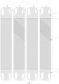
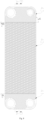
- Multi-stage flow distribution plate group for heat exchanger comprising at least two pairs of unit plate groups, each pair of the said unit plate group includes a first plate 1 and a second plate 2 that are stacked; both the said first plate 1 and the second plate 2 include a main panel and a surrounding baffle 3, the main panel includes a shunt area 41, a main heat exchanging area 42 and the confluence area 43; shunt ribs 44 are set between the said shunt area 41 and the main heat exchanging area 42 as well as between the main heat exchanging area 42 and the confluence area 43, which are used to evenly distribute the medium flowing from the shunt area 41 into the main heat exchanging area 42 and the medium flowing from the main heat exchanging area 42 into the confluence area 43.
- the shunt ribs 44 are set to make the medium flowing from the shunt area 41 to the main heat exchanging area 42 evenly distributed at the split ribs 44, which is conducive to the uniform flow of the medium into the main heat exchanging area 42. After the medium completes the heat exchange in the main heat exchanging area 42, it then collected together evenly undergoes a secondary distribution through the shunt ribs 44 located between the main heat exchanging area 42 and confluence area 43, and flowed to the exit through the confluence area 43. The medium goes through two even distributions during the whole process, this allows more homogeneous circulation of the medium in the path, which helps to increase the efficiency and stability of heat exchange in a long run.
- the arrangement of the shunt rib 44 can provide effective support for the entire heat exchanging plate, improve the strength of the panel, and help solve the problem of deformation.
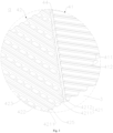
- the said shunt area 41 is provided with a few ridges I 411, and the neighboring ridges I 411 form valley I 412 in between, the angle formed by the ridge I 411 and the shunt rib 44 is ⁇ ;
- the said main heat exchanging area 42 is provided with a few ridges II 421, neighboring ridge II 421 form the valley II 422 in between, the angle formed by the said ridge II 421 and the shunt rib 44 is ⁇ ;
- the said confluence area 43 is provided with a few ridges III 431, neighboring ridge III 431 form the valley III 432, and the angle formed by the said ridge III 431 and the shunt rib 44 is ⁇ ;
- the angle ⁇ is not equal to ⁇ ;
- the angle ⁇ is not equal to ⁇ .
- the medium Since ⁇ is not equal to ⁇ , the medium will not flow directly from the shunt area 41 to the main heat exchanging area 42, rather, it will be distributed at the shunt rib 44 before entering the main heat exchanging area 42. Since the angle ⁇ is not equal to ⁇ , the medium is thus first evenly distributed before entering the confluence area 43.
- the said angle ⁇ is 30- 45° which is equal to ⁇ , and the angle ⁇ is 20-30°, if the said plate group is used for evaporators. Since evaporation is the process of converting liquid to vapor, setting the angle ⁇ (or ⁇ ) to a larger value is more conducive to the rapid flow of liquid (or vapor) into (or rapid evaporation out from) the main heat exchanging area 42, thereby improving evaporation performance.
- the said angle ⁇ is 20- 30° which is equal to ⁇ , and the angle ⁇ is 30-45°, if the said plate group is used for condensers. Since condensation is the process of converting vapor to liquid, setting the ⁇ (or ⁇ ) angle to a larger value is more conducive to the rapid flow of vapor (or liquid) into (or out of) the main heat exchanging area 42, thereby increasing condensation performance.
- the said ridge I 411, ridge II 421 and ridge III 431 all tilt in the same direction; the second plate 2 rotates 180° relative to the first plate 1; the height of the said ridge I 411, ridge II 421 and ridge III 431 are identical, equal to twice the height of the shunt rib 44.
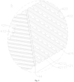
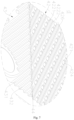
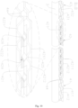
- the said valley II 422 of the first plate 1 is provided with a few convex grooves 423 protruding toward the ridge II 421 and, the said ridge II 421 of the second plate 2 is provided with a few concave grooves 424 denting toward the valley II 422.
- the convex grooves 423 set on valley II 422 and the grooves 424 set on ridge II 421 help to reduce the pressure drop, enable the medium to circulate faster and more homogenously, which improves the heat exchanging performance.
- the said convex groove 423 and the concave groove 424 are equal in size, and are evenly distributed on their corresponding valley II 422 and ridge II 421.
- the heights of the said indentation 425 and the bulge 426 are equal, being half of the height of the ridge II 421.
- the top of the ridge II 421 of the first plate 1 is divided by the indentations 425 into a first ridge II 4211 and a second ridge II 4212; the bottom of the said valley II 422 of the second plate 2 is divided by the bulges 426 into the first valley II 4221 and the second valley II 4222, the top width of the first ridge II 4211, the top width of the second ridge II 4212, the bottom width of the valley II 422 of the first plate 1, the bottom width of the first valley II 4221, the bottom width of the second valley II 4222 and the top width of the ridge II 421 of the second plate 2 are all equal; the bottom width of the indentation 425 and the top width of the bulge 426 are equal; the top width of the first ridge II 4211 is larger than the top width of the bulge 426.
Landscapes
- Engineering & Computer Science (AREA)
- Physics & Mathematics (AREA)
- Thermal Sciences (AREA)
- Mechanical Engineering (AREA)
- General Engineering & Computer Science (AREA)
- Heat-Exchange Devices With Radiators And Conduit Assemblies (AREA)
Applications Claiming Priority (1)
| Application Number | Priority Date | Filing Date | Title |
|---|---|---|---|
| CN201911242835.7A CN110749215A (zh) | 2019-12-06 | 2019-12-06 | 一种多级分流的钎焊换热器板片组 |
Publications (3)
| Publication Number | Publication Date |
|---|---|
| EP3832243A1 EP3832243A1 (en) | 2021-06-09 |
| EP3832243C0 EP3832243C0 (en) | 2024-03-27 |
| EP3832243B1 true EP3832243B1 (en) | 2024-03-27 |
Family
ID=69285740
Family Applications (1)
| Application Number | Title | Priority Date | Filing Date |
|---|---|---|---|
| EP20020579.7A Active EP3832243B1 (en) | 2019-12-06 | 2020-12-01 | Multi-stage flow distribution plate group for heat exchanger |
Country Status (3)
| Country | Link |
|---|---|
| EP (1) | EP3832243B1 (pl) |
| CN (1) | CN110749215A (pl) |
| PL (1) | PL3832243T3 (pl) |
Families Citing this family (7)
| Publication number | Priority date | Publication date | Assignee | Title |
|---|---|---|---|---|
| CN112414183B (zh) * | 2020-06-02 | 2025-04-08 | 浙江三花智能控制股份有限公司 | 板式换热器 |
| CN112432529B (zh) * | 2020-06-02 | 2025-03-18 | 浙江三花智能控制股份有限公司 | 板式换热器 |
| CN112577342A (zh) * | 2020-12-21 | 2021-03-30 | 山东信悦机械有限公司 | 换热板和换热器 |
| SE546498C2 (en) * | 2022-06-22 | 2024-11-19 | Alfa Laval Corp Ab | Plate heat exchanger |
| PL4310428T3 (pl) | 2022-07-22 | 2025-04-14 | Alfa Laval Corporate Ab | Lutowany płytowy wymiennik ciepła |
| CN118009793A (zh) * | 2024-03-25 | 2024-05-10 | 浙江银轮机械股份有限公司 | 一种换热板和换热器 |
| CN118347331B (zh) * | 2024-05-22 | 2025-11-21 | 浙江英特科技股份有限公司 | 一种换热板片 |
Family Cites Families (25)
| Publication number | Priority date | Publication date | Assignee | Title |
|---|---|---|---|---|
| CN2090959U (zh) * | 1991-03-01 | 1991-12-18 | 徐复昌 | 板式热交换器 |
| SE528879C2 (sv) * | 2005-07-04 | 2007-03-06 | Alfa Laval Corp Ab | Värmeväxlarplatta, par av två värmeväxlarplattor samt plattpaket för plattvärmeväxlare |
| SE531472C2 (sv) * | 2005-12-22 | 2009-04-14 | Alfa Laval Corp Ab | Värmeväxlare med värmeöverföringsplatta med jämn lastfördelning på kontaktpunkter vid portområden |
| CN201163159Y (zh) * | 2008-01-18 | 2008-12-10 | 江阴博格机械制冷技术有限公司 | 钎焊板式换热器 |
| SE532524C2 (sv) * | 2008-06-13 | 2010-02-16 | Alfa Laval Corp Ab | Värmeväxlarplatta samt värmeväxlarmontage innefattandes fyra plattor |
| JP5243623B2 (ja) * | 2009-02-04 | 2013-07-24 | アルファ ラヴァル コーポレイト アクチボラゲット | プレート式熱交換器 |
| CN201867114U (zh) * | 2010-11-26 | 2011-06-15 | 辽宁远东换热设备制造有限公司 | 一种板式换热器的换热板片 |
| CN202869325U (zh) * | 2012-09-12 | 2013-04-10 | 江苏宝得换热设备有限公司 | 一种带二次节流的板式换热器 |
| CN102809311B (zh) * | 2012-09-12 | 2015-05-20 | 江苏宝得换热设备有限公司 | 一种带二次节流的板式换热器 |
| CN203586888U (zh) * | 2013-11-07 | 2014-05-07 | 山东旺泰机械科技有限公司 | 全焊式板式换热器的换热板组 |
| US10837717B2 (en) * | 2013-12-10 | 2020-11-17 | Swep International Ab | Heat exchanger with improved flow |
| CN205279837U (zh) * | 2015-11-27 | 2016-06-01 | Omexell(济南)传热技术有限公司 | 一种x型换热均流区换热板片 |
| CN205383918U (zh) * | 2016-02-03 | 2016-07-13 | 上海板换机械设备有限公司 | 用于焊接式板式换热器的换热板、换热板对、板组及焊接式板式换热器 |
| CN106197123A (zh) * | 2016-08-26 | 2016-12-07 | 天津博泰换热设备有限公司 | 一种宽通道换热板片 |
| PL3351886T3 (pl) * | 2017-01-19 | 2019-09-30 | Alfa Laval Corporate Ab | Płyta wymiennika ciepła i wymiennik ciepła |
| CN206488672U (zh) * | 2017-01-23 | 2017-09-12 | 江苏宝得换热设备有限公司 | 非对称式波纹钎焊热交换器 |
| EP3396293A1 (en) * | 2017-04-26 | 2018-10-31 | Alfa Laval Corporate AB | Heat transfer plate and heat exchanger comprising a plurality of such heat transfer plates |
| CN207180438U (zh) * | 2017-06-09 | 2018-04-03 | 兰州兰石换热设备有限责任公司 | 板式换热器主换热板片波纹区结构 |
| CN207035928U (zh) * | 2017-11-01 | 2018-02-23 | 上海板换机械设备有限公司 | 一种换热板及其换热器 |
| CN207662255U (zh) * | 2017-12-15 | 2018-07-27 | 山东普瑞普勒能源科技有限公司 | 一种均匀流速式板式换热器板片 |
| CN108375313B (zh) * | 2018-04-26 | 2024-04-19 | 江苏宝得换热设备股份有限公司 | 一种多级分配板式换热器 |
| CN208443234U (zh) * | 2018-04-26 | 2019-01-29 | 江苏宝得换热设备股份有限公司 | 一种多级分配板式换热器 |
| CN108827057A (zh) * | 2018-04-30 | 2018-11-16 | 南京理工大学 | 一种新型鱼骨形的板式换热器复合波纹板片 |
| CN108759523A (zh) * | 2018-06-07 | 2018-11-06 | 湖北捷玛换热设备制造有限公司 | 曲线型全焊式板式换热器的换热板组 |
| CN211012599U (zh) * | 2019-12-06 | 2020-07-14 | 江苏唯益换热器有限公司 | 一种多级分流的钎焊换热器板片组 |
-
2019
- 2019-12-06 CN CN201911242835.7A patent/CN110749215A/zh active Pending
-
2020
- 2020-12-01 PL PL20020579.7T patent/PL3832243T3/pl unknown
- 2020-12-01 EP EP20020579.7A patent/EP3832243B1/en active Active
Also Published As
| Publication number | Publication date |
|---|---|
| EP3832243C0 (en) | 2024-03-27 |
| CN110749215A (zh) | 2020-02-04 |
| EP3832243A1 (en) | 2021-06-09 |
| PL3832243T3 (pl) | 2024-06-17 |
Similar Documents
| Publication | Publication Date | Title |
|---|---|---|
| EP3832243B1 (en) | Multi-stage flow distribution plate group for heat exchanger | |
| US10352598B2 (en) | Heat exchanger, in particular a condenser | |
| US11118848B2 (en) | Heat-exchanging plate, and plate heat exchanger using same | |
| JP2007518053A (ja) | 熱交換器およびその熱交換モジュール | |
| SE0850140A1 (sv) | Platta och packning till en plattvärmeväxlare | |
| US10871330B2 (en) | Plate heat exchanger | |
| WO2022007444A1 (zh) | 板管式换热器 | |
| CN218723446U (zh) | 翅片结构及其换热器 | |
| US6942024B2 (en) | Corrugated heat exchange element | |
| CN111271996B (zh) | 一种具有非对称通道的板式换热器 | |
| CN211178074U (zh) | 一种多级分流的钎焊换热器板片组用第二板片 | |
| CN110779361B (zh) | 一种具有八字形分配通道的钎焊换热板片组 | |
| CN211178073U (zh) | 一种多级分流的钎焊换热器板片组用第一板片 | |
| JP7328348B2 (ja) | 伝熱板、およびプレート熱交換器 | |
| CN211012598U (zh) | 一种可提高流通均匀性的钎焊换热器板片组 | |
| WO2021002474A1 (ja) | 熱交換器 | |
| CN110749217A (zh) | 一种多级分流的钎焊换热器板片组用第一板片 | |
| CN211012599U (zh) | 一种多级分流的钎焊换热器板片组 | |
| CN205300358U (zh) | 一种换热器板片结构 | |
| CN110749214A (zh) | 一种可提高流通均匀性的钎焊换热器板片组 | |
| CN110749216A (zh) | 一种多级分流的钎焊换热器板片组用第二板片 | |
| CN110545646A (zh) | 一种冷凝器 | |
| CN210952455U (zh) | 一种具有八字形分配通道的钎焊换热板片组 | |
| EP4556840A1 (en) | Plate heat exchange module | |
| JPS63131993A (ja) | 熱交換器 |
Legal Events
| Date | Code | Title | Description |
|---|---|---|---|
| PUAI | Public reference made under article 153(3) epc to a published international application that has entered the european phase |
Free format text: ORIGINAL CODE: 0009012 |
|
| STAA | Information on the status of an ep patent application or granted ep patent |
Free format text: STATUS: REQUEST FOR EXAMINATION WAS MADE |
|
| 17P | Request for examination filed |
Effective date: 20201215 |
|
| AK | Designated contracting states |
Kind code of ref document: A1 Designated state(s): AL AT BE BG CH CY CZ DE DK EE ES FI FR GB GR HR HU IE IS IT LI LT LU LV MC MK MT NL NO PL PT RO RS SE SI SK SM TR |
|
| 19U | Interruption of proceedings before grant |
Effective date: 20220813 |
|
| 19W | Proceedings resumed before grant after interruption of proceedings |
Effective date: 20230403 |
|
| GRAP | Despatch of communication of intention to grant a patent |
Free format text: ORIGINAL CODE: EPIDOSNIGR1 |
|
| STAA | Information on the status of an ep patent application or granted ep patent |
Free format text: STATUS: GRANT OF PATENT IS INTENDED |
|
| RIC1 | Information provided on ipc code assigned before grant |
Ipc: F28F 3/04 20060101ALI20231026BHEP Ipc: F28D 9/00 20060101AFI20231026BHEP |
|
| INTG | Intention to grant announced |
Effective date: 20231116 |
|
| GRAS | Grant fee paid |
Free format text: ORIGINAL CODE: EPIDOSNIGR3 |
|
| GRAA | (expected) grant |
Free format text: ORIGINAL CODE: 0009210 |
|
| STAA | Information on the status of an ep patent application or granted ep patent |
Free format text: STATUS: THE PATENT HAS BEEN GRANTED |
|
| AK | Designated contracting states |
Kind code of ref document: B1 Designated state(s): AL AT BE BG CH CY CZ DE DK EE ES FI FR GB GR HR HU IE IS IT LI LT LU LV MC MK MT NL NO PL PT RO RS SE SI SK SM TR |
|
| REG | Reference to a national code |
Ref country code: GB Ref legal event code: FG4D |
|
| REG | Reference to a national code |
Ref country code: CH Ref legal event code: EP |
|
| REG | Reference to a national code |
Ref country code: DE Ref legal event code: R096 Ref document number: 602020027737 Country of ref document: DE |
|
| REG | Reference to a national code |
Ref country code: IE Ref legal event code: FG4D |
|
| U01 | Request for unitary effect filed |
Effective date: 20240328 |
|
| U07 | Unitary effect registered |
Designated state(s): AT BE BG DE DK EE FI FR IT LT LU LV MT NL PT SE SI Effective date: 20240408 |
|
| U1N | Appointed representative for the unitary patent procedure changed after the registration of the unitary effect |
Representative=s name: MUSIL, DOBROSLAV; CZ |
|
| PG25 | Lapsed in a contracting state [announced via postgrant information from national office to epo] |
Ref country code: GR Free format text: LAPSE BECAUSE OF FAILURE TO SUBMIT A TRANSLATION OF THE DESCRIPTION OR TO PAY THE FEE WITHIN THE PRESCRIBED TIME-LIMIT Effective date: 20240628 |
|
| PG25 | Lapsed in a contracting state [announced via postgrant information from national office to epo] |
Ref country code: RS Free format text: LAPSE BECAUSE OF FAILURE TO SUBMIT A TRANSLATION OF THE DESCRIPTION OR TO PAY THE FEE WITHIN THE PRESCRIBED TIME-LIMIT Effective date: 20240627 Ref country code: HR Free format text: LAPSE BECAUSE OF FAILURE TO SUBMIT A TRANSLATION OF THE DESCRIPTION OR TO PAY THE FEE WITHIN THE PRESCRIBED TIME-LIMIT Effective date: 20240327 |
|
| PG25 | Lapsed in a contracting state [announced via postgrant information from national office to epo] |
Ref country code: RS Free format text: LAPSE BECAUSE OF FAILURE TO SUBMIT A TRANSLATION OF THE DESCRIPTION OR TO PAY THE FEE WITHIN THE PRESCRIBED TIME-LIMIT Effective date: 20240627 Ref country code: NO Free format text: LAPSE BECAUSE OF FAILURE TO SUBMIT A TRANSLATION OF THE DESCRIPTION OR TO PAY THE FEE WITHIN THE PRESCRIBED TIME-LIMIT Effective date: 20240627 Ref country code: HR Free format text: LAPSE BECAUSE OF FAILURE TO SUBMIT A TRANSLATION OF THE DESCRIPTION OR TO PAY THE FEE WITHIN THE PRESCRIBED TIME-LIMIT Effective date: 20240327 Ref country code: GR Free format text: LAPSE BECAUSE OF FAILURE TO SUBMIT A TRANSLATION OF THE DESCRIPTION OR TO PAY THE FEE WITHIN THE PRESCRIBED TIME-LIMIT Effective date: 20240628 |
|
| PG25 | Lapsed in a contracting state [announced via postgrant information from national office to epo] |
Ref country code: IS Free format text: LAPSE BECAUSE OF FAILURE TO SUBMIT A TRANSLATION OF THE DESCRIPTION OR TO PAY THE FEE WITHIN THE PRESCRIBED TIME-LIMIT Effective date: 20240727 |
|
| PG25 | Lapsed in a contracting state [announced via postgrant information from national office to epo] |
Ref country code: SM Free format text: LAPSE BECAUSE OF FAILURE TO SUBMIT A TRANSLATION OF THE DESCRIPTION OR TO PAY THE FEE WITHIN THE PRESCRIBED TIME-LIMIT Effective date: 20240327 |
|
| PG25 | Lapsed in a contracting state [announced via postgrant information from national office to epo] |
Ref country code: ES Free format text: LAPSE BECAUSE OF FAILURE TO SUBMIT A TRANSLATION OF THE DESCRIPTION OR TO PAY THE FEE WITHIN THE PRESCRIBED TIME-LIMIT Effective date: 20240327 |
|
| PG25 | Lapsed in a contracting state [announced via postgrant information from national office to epo] |
Ref country code: CZ Free format text: LAPSE BECAUSE OF FAILURE TO SUBMIT A TRANSLATION OF THE DESCRIPTION OR TO PAY THE FEE WITHIN THE PRESCRIBED TIME-LIMIT Effective date: 20240327 |
|
| PG25 | Lapsed in a contracting state [announced via postgrant information from national office to epo] |
Ref country code: SK Free format text: LAPSE BECAUSE OF FAILURE TO SUBMIT A TRANSLATION OF THE DESCRIPTION OR TO PAY THE FEE WITHIN THE PRESCRIBED TIME-LIMIT Effective date: 20240327 |
|
| PG25 | Lapsed in a contracting state [announced via postgrant information from national office to epo] |
Ref country code: SM Free format text: LAPSE BECAUSE OF FAILURE TO SUBMIT A TRANSLATION OF THE DESCRIPTION OR TO PAY THE FEE WITHIN THE PRESCRIBED TIME-LIMIT Effective date: 20240327 Ref country code: SK Free format text: LAPSE BECAUSE OF FAILURE TO SUBMIT A TRANSLATION OF THE DESCRIPTION OR TO PAY THE FEE WITHIN THE PRESCRIBED TIME-LIMIT Effective date: 20240327 Ref country code: RO Free format text: LAPSE BECAUSE OF FAILURE TO SUBMIT A TRANSLATION OF THE DESCRIPTION OR TO PAY THE FEE WITHIN THE PRESCRIBED TIME-LIMIT Effective date: 20240327 Ref country code: IS Free format text: LAPSE BECAUSE OF FAILURE TO SUBMIT A TRANSLATION OF THE DESCRIPTION OR TO PAY THE FEE WITHIN THE PRESCRIBED TIME-LIMIT Effective date: 20240727 Ref country code: ES Free format text: LAPSE BECAUSE OF FAILURE TO SUBMIT A TRANSLATION OF THE DESCRIPTION OR TO PAY THE FEE WITHIN THE PRESCRIBED TIME-LIMIT Effective date: 20240327 Ref country code: CZ Free format text: LAPSE BECAUSE OF FAILURE TO SUBMIT A TRANSLATION OF THE DESCRIPTION OR TO PAY THE FEE WITHIN THE PRESCRIBED TIME-LIMIT Effective date: 20240327 |
|
| REG | Reference to a national code |
Ref country code: DE Ref legal event code: R097 Ref document number: 602020027737 Country of ref document: DE |
|
| U20 | Renewal fee for the european patent with unitary effect paid |
Year of fee payment: 5 Effective date: 20241216 |
|
| PLBE | No opposition filed within time limit |
Free format text: ORIGINAL CODE: 0009261 |
|
| STAA | Information on the status of an ep patent application or granted ep patent |
Free format text: STATUS: NO OPPOSITION FILED WITHIN TIME LIMIT |
|
| 26N | No opposition filed |
Effective date: 20250103 |
|
| PG25 | Lapsed in a contracting state [announced via postgrant information from national office to epo] |
Ref country code: MC Free format text: LAPSE BECAUSE OF FAILURE TO SUBMIT A TRANSLATION OF THE DESCRIPTION OR TO PAY THE FEE WITHIN THE PRESCRIBED TIME-LIMIT Effective date: 20240327 |
|
| REG | Reference to a national code |
Ref country code: CH Ref legal event code: PL |
|
| PG25 | Lapsed in a contracting state [announced via postgrant information from national office to epo] |
Ref country code: CH Free format text: LAPSE BECAUSE OF NON-PAYMENT OF DUE FEES Effective date: 20241231 |
|
| PG25 | Lapsed in a contracting state [announced via postgrant information from national office to epo] |
Ref country code: IE Free format text: LAPSE BECAUSE OF NON-PAYMENT OF DUE FEES Effective date: 20241201 |
|
| U20 | Renewal fee for the european patent with unitary effect paid |
Year of fee payment: 6 Effective date: 20251127 |
|
| PGFP | Annual fee paid to national office [announced via postgrant information from national office to epo] |
Ref country code: GB Payment date: 20251229 Year of fee payment: 6 |
|
| PGFP | Annual fee paid to national office [announced via postgrant information from national office to epo] |
Ref country code: PL Payment date: 20251127 Year of fee payment: 6 |
|
| PG25 | Lapsed in a contracting state [announced via postgrant information from national office to epo] |
Ref country code: CY Free format text: LAPSE BECAUSE OF FAILURE TO SUBMIT A TRANSLATION OF THE DESCRIPTION OR TO PAY THE FEE WITHIN THE PRESCRIBED TIME-LIMIT; INVALID AB INITIO Effective date: 20201201 |