EP3832222A1 - Vortex ring generation device - Google Patents
Vortex ring generation device Download PDFInfo
- Publication number
- EP3832222A1 EP3832222A1 EP19867031.7A EP19867031A EP3832222A1 EP 3832222 A1 EP3832222 A1 EP 3832222A1 EP 19867031 A EP19867031 A EP 19867031A EP 3832222 A1 EP3832222 A1 EP 3832222A1
- Authority
- EP
- European Patent Office
- Prior art keywords
- vortex ring
- component
- discharge port
- range
- passage
- Prior art date
- Legal status (The legal status is an assumption and is not a legal conclusion. Google has not performed a legal analysis and makes no representation as to the accuracy of the status listed.)
- Granted
Links
Images

Classifications
-
- F—MECHANICAL ENGINEERING; LIGHTING; HEATING; WEAPONS; BLASTING
- F15—FLUID-PRESSURE ACTUATORS; HYDRAULICS OR PNEUMATICS IN GENERAL
- F15D—FLUID DYNAMICS, i.e. METHODS OR MEANS FOR INFLUENCING THE FLOW OF GASES OR LIQUIDS
- F15D1/00—Influencing flow of fluids
- F15D1/009—Influencing flow of fluids by means of vortex rings
-
- B—PERFORMING OPERATIONS; TRANSPORTING
- B05—SPRAYING OR ATOMISING IN GENERAL; APPLYING FLUENT MATERIALS TO SURFACES, IN GENERAL
- B05B—SPRAYING APPARATUS; ATOMISING APPARATUS; NOZZLES
- B05B17/00—Apparatus for spraying or atomising liquids or other fluent materials, not covered by the preceding groups
- B05B17/04—Apparatus for spraying or atomising liquids or other fluent materials, not covered by the preceding groups operating with special methods
- B05B17/06—Apparatus for spraying or atomising liquids or other fluent materials, not covered by the preceding groups operating with special methods using ultrasonic or other kinds of vibrations
-
- F—MECHANICAL ENGINEERING; LIGHTING; HEATING; WEAPONS; BLASTING
- F15—FLUID-PRESSURE ACTUATORS; HYDRAULICS OR PNEUMATICS IN GENERAL
- F15C—FLUID-CIRCUIT ELEMENTS PREDOMINANTLY USED FOR COMPUTING OR CONTROL PURPOSES
- F15C1/00—Circuit elements having no moving parts
- F15C1/14—Stream-interaction devices; Momentum-exchange devices, e.g. operating by exchange between two orthogonal fluid jets ; Proportional amplifiers
-
- F—MECHANICAL ENGINEERING; LIGHTING; HEATING; WEAPONS; BLASTING
- F15—FLUID-PRESSURE ACTUATORS; HYDRAULICS OR PNEUMATICS IN GENERAL
- F15C—FLUID-CIRCUIT ELEMENTS PREDOMINANTLY USED FOR COMPUTING OR CONTROL PURPOSES
- F15C1/00—Circuit elements having no moving parts
- F15C1/16—Vortex devices, i.e. devices in which use is made of the pressure drop associated with vortex motion in a fluid
-
- F—MECHANICAL ENGINEERING; LIGHTING; HEATING; WEAPONS; BLASTING
- F24—HEATING; RANGES; VENTILATING
- F24F—AIR-CONDITIONING; AIR-HUMIDIFICATION; VENTILATION; USE OF AIR CURRENTS FOR SCREENING
- F24F2221/00—Details or features not otherwise provided for
- F24F2221/46—Air flow forming a vortex
-
- F—MECHANICAL ENGINEERING; LIGHTING; HEATING; WEAPONS; BLASTING
- F24—HEATING; RANGES; VENTILATING
- F24F—AIR-CONDITIONING; AIR-HUMIDIFICATION; VENTILATION; USE OF AIR CURRENTS FOR SCREENING
- F24F7/00—Ventilation
- F24F7/003—Ventilation in combination with air cleaning
-
- F—MECHANICAL ENGINEERING; LIGHTING; HEATING; WEAPONS; BLASTING
- F24—HEATING; RANGES; VENTILATING
- F24F—AIR-CONDITIONING; AIR-HUMIDIFICATION; VENTILATION; USE OF AIR CURRENTS FOR SCREENING
- F24F8/00—Treatment, e.g. purification, of air supplied to human living or working spaces otherwise than by heating, cooling, humidifying or drying
- F24F8/80—Self-contained air purifiers
Definitions
- the present disclosure relates to a vortex ring generation device.
- Patent Document 1 discloses a device that generates a vortex ring and supplies the vortex ring containing, for example, a scent component to a predetermined region.
- the vortex ring and a straight flow passing through the inside of the vortex ring are generated by limiting a UT/R (a ratio of an extrusion volume to the radius of an outlet) range and a Reynolds number range of air, where U represents the velocity of the extrusion air, T represents the discharge time, and R represents the radius of an opening of a discharge port.
- UT/R a ratio of an extrusion volume to the radius of an outlet
- Patent Document 1 Japanese Unexamined Patent Publication No. 2008-018394
- a first aspect of the present disclosure is directed to a vortex ring generation device including: a casing (20) having a gas passage (C) and a discharge port (25); and an extrusion mechanism (30) that extrudes a gas in the gas passage (C) such that the gas in a vortex ring shape is discharged from the discharge port (25).
- V (m 3 ) represents an extrusion volume
- D (m) represents a diameter of the discharge port (25)
- L (m) represents a length of a cylinder (an equivalent length of a cylinder) having the diameter D and the volume V
- Re represents a Reynolds number of the discharged gas
- a range of UT/R described in Patent Document 1 is a wide range of 1 ⁇ UT/R ⁇ 5 (0.5 ⁇ L/D ⁇ 2.5).
- UT/R exceeds 4
- the vortex ring becomes unstable and lingers.
- Patent Document 1 describes a range including a Reynolds number Re exceeding 10000. In fact, when the Reynolds number Re exceeds 3000, the vortex ring becomes significantly turbulent and moves while diffusing, thereby easily disappearing.
- the Reynolds number Re and the L/D ratio are included in a range (A) satisfying relationships of 500 ⁇ Re ⁇ 3000 and 0.5 ⁇ L/D ⁇ 2.0.
- A a stable vortex ring including almost no straight flow is generated.
- a second aspect of the present disclosure is an embodiment of the first aspect.
- relationships of 1000 ⁇ Re ⁇ 2500 and 0.75 ⁇ L/D ⁇ 2.0 are satisfied.
- the Reynolds number Re and the L/D ratio are included in a range (B) satisfying relationships of 1000 ⁇ Re ⁇ 2500 and 0.75 ⁇ L/D ⁇ 2.0.
- a vortex ring more stable than that in the range (A) is generated.
- a third aspect of the present disclosure is an embodiment of the second aspect.
- relationships of 1500 ⁇ Re ⁇ 2000 and 1.0 ⁇ L/D ⁇ 2.0 are satisfied.
- the Reynolds number Re and the L/D ratio are included in a range (C) satisfying relationships of 1500 ⁇ Re ⁇ 2000 and 1.0 ⁇ L/D ⁇ 2.0.
- a vortex ring even more stable than that in the range (B) is generated.
- a fourth aspect of the present disclosure is an embodiment of any one of the first to third aspects.
- U represents a blow-out flow rate (m/s)
- relationships of 0.06 ⁇ D ⁇ 0.15, 0.12 ⁇ L ⁇ 0.3, and 0.3 ⁇ U ⁇ 0.75 are satisfied.
- the equivalent length L (m) of the cylinder and the blow-out flow rate U (m/s) are set to satisfy the diameter D (m) of 0.06 ⁇ D ⁇ 0.15. Therefore, setting the diameter D (m) of the discharge port (25) to 0.06 ⁇ D ⁇ 0.15 enables a stable vortex ring achieving an outreach A of 2 m ⁇ A ⁇ 5 (m) to be generated.
- a vortex ring generation device (10) discharges vortex ring-shaped air (a vortex ring (R)).
- the vortex ring generation device (10) causes a predetermined discharge component to be contained in the vortex ring (R), and then supplies the vortex ring (R) containing the discharge component to, for example, a subject.
- the discharge component contains substances such as a scent component, water vapor, and a substance having predetermined efficacy.
- the discharge component is preferably a gas, but may be a liquid. In the case of liquid, the discharge component is preferably a particulate liquid.
- the vortex ring generation device (10) includes: a casing (20) having a discharge port (25); an extrusion mechanism (30); a passage forming member (40); and a component supply device (50).
- An air passage (gas passage) (C) through which air flows is formed inside the casing (20).
- the air in the air passage (C) is extruded by the extrusion mechanism (30), formed into the vortex ring (R), and discharged from the discharge port (25).
- the vortex ring (R) discharged from the discharge port (25) contains the discharge component supplied from the component supply device (50).
- the casing (20) includes a casing body (21) having a front side open, and a substantially plate-like front panel (22) blocking the open face on the front side of the casing body (21).
- the casing (20) has a hollow cuboid shape.
- a middle portion of the front panel (22) has the discharge port (25) in the circular shape passing therethrough in a front-rear direction.
- a peripheral wall (23) in a substantially cylindrical shape continues on a rear surface of the front panel (22).
- the peripheral wall (23) extends rearward from an inner peripheral edge (26) of the discharge port (25).
- the peripheral wall (23) has a tapered shape whose diameter becomes smaller frontward.
- An outer peripheral end of the peripheral wall (23) is fixed to an inner wall of the casing body (21).
- a front leading end portion of the peripheral wall (23) is continuous with the inner peripheral edge (26) of the discharge port (25).
- An center axis of the peripheral wall (23) substantially coincides with that of the discharge port (25).
- the passage forming member (40) is disposed rearward of the peripheral wall (23).
- the passage forming member (40) is formed in a substantially cylindrical shape along an inner peripheral surface of the peripheral wall (23).
- the passage forming member (40) has a tapered shape whose diameter becomes smaller frontward (i.e., downstream of the air passage (C)).
- a center axis of the passage forming member (40) substantially coincides with that of the discharge port (25).
- the center axis of the passage forming member (40) substantially coincides with that of the peripheral wall (23).
- a component chamber (27) in which the discharge component is temporarily stored is defined in space surrounded by the inner wall of the casing body (21), the peripheral wall (23), and the passage forming member (40).
- the component chamber (27) is a substantially cylindrical space formed around the passage forming member (40).
- the extrusion mechanism (30) is disposed in the rearward inside the casing (20).
- the extrusion mechanism (30) has a vibration plate (31) that is a movable member, and a linear actuator (35) that displaces the vibration plate (31) back and forth.
- the vibration plate (31) includes a vibration plate body (32) and a frame-shaped elastic support (33) disposed at an outer peripheral edge of the vibration plate body (32).
- the vibration plate (31) is fixed to an inner wall of the casing (20) via the elastic support (33).
- the linear actuator (35) constitutes a drive unit that vibrates the vibration plate (31) back and forth.
- a base end (rear end) of the linear actuator (35) is supported by a rear wall of the casing body (21).
- a leading end (front end) of the linear actuator (35) is coupled with a center portion of the vibration plate (31).
- the linear actuator (35) vibrates the vibration plate (31) between a reference position and an extrusion position.
- the air indicated by an open arrow in FIG. 1 ) in the air passage (C) is extruded forward.
- the air passage (C) extends from the vibration plate (31) to the discharge port (25) in the casing (20).
- the air passage (C) includes a first passage (C1) and a second passage (C2) continuous with a downstream end of the first passage (C1).
- the first passage (C1) is surrounded by the inner wall of the casing body (21).
- a passage area of the first passage (C1) is constant.
- the second passage (C2) is formed inside the passage forming member (40). Specifically, the second passage (C2) is surrounded by the peripheral wall (23).
- the second passage (C2) constitutes a throttle passage whose passage area becomes smaller toward its downstream. Thus, in the second passage (C2), the flow rate of air gradually increases toward its downstream.
- the component supply device (50) supplies, into the casing (20), the discharge component to be applied to the vortex ring (R). Specifically, the component supply device (50) supplies, via a supply passage (51), the predetermined discharge component to the component chamber (27) defined inside the casing (20).
- the component supply device (50) includes a component generation unit (not shown) that generates the discharge component and a conveyance unit (not shown) that conveys the discharge component generated in the generation unit.
- the component generation unit is, for example, of a vaporizing type that vaporizes the discharge component from a component raw material.
- the conveyance unit is, for example, an air pump.
- the component supply device (50) appropriately supplies, to the component chamber (27), the discharge component whose concentration has been adjusted to a predetermined concentration.
- the vortex ring generation device (10) has a component supply port (60) for supplying the discharge component to the air passage (C).
- the casing (20) has one component supply port (60).
- the component supply port (60) is located adjacent to the discharge port (25).
- the component supply port (60) is disposed between a downstream end (41) of the passage forming member (40) in a cylinder axial direction and the inner peripheral edge (26) of the discharge port (25).
- one annular (strictly speaking, toric) component supply port (60) is formed around the downstream end of the air passage (C).
- one annular component supply port (60) is formed near the discharge port (25) in the air passage (C).
- the linear actuator (35) vibrates the vibration plate (31).
- the vibration plate (31) deforms forward, the volume of the air passage (C) decreases. As a result, the air in the air passage (C) flows toward the discharge port (25).
- the air in the first passage (C1) flows into the second passage (C2).
- the passage area gradually decreases, so that the flow rate of air increases.
- the pressure of the air decreases.
- an outlet end of the second passage (C2) has the smallest passage area. Therefore, the flow rate of the air at the outlet end of the second passage (C2) is substantially the highest in the air passage (C). Consequently, the pressure of the air at the outlet end of the second passage (C2) is substantially the lowest.
- the component supply port (60) is located at the outlet end of the second passage (C2). Therefore, when the air at low pressure passes through the component supply port (60), the discharge component in the component chamber (27) is sucked into the air passage (C) due to the difference between the pressure of the air and the pressure in the component chamber (27). When the discharge component in the component chamber (27) is sucked into the air passage (C), the discharge component is dispersed in the air passing through the component supply port (60).
- the constant flow rate of the air passing through the component supply port (60) allows a constant amount of the discharge component to be sucked from the component supply port (60). This allows the concentrations of the discharge component in the air and the vortex ring (R) to be controlled to be constant.
- the discharge component in the component chamber (27) is dispersed over the entire circumference of the air passage (C). Further, the discharge component is easily applied to the air flowing through the air passage (C), in particular, to the air near the outer periphery. This allows, in the air passage (C), the discharge component to be uniformly applied to the air near the outer periphery.
- the air containing the discharge component reaches the discharge port (25) immediately.
- the air passing through the discharge port (25) has a relatively high flow rate, whereas the air around the discharge port (25) is still. For this reason, a shearing force acts on the air at discontinuous planes of both air flows, and a vortex flow is generated adjacent to an outer peripheral edge of the discharge port (25).
- the vortex flow forms a vortex ring-shaped air (vortex ring (R) schematically shown in FIG. 1 ) moving forward from the discharge port (25).
- the vortex ring (R) containing the discharge component is supplied to the subject.
- the discharge component is supplied over the entire circumference of the air flow from the component supply port (60). Therefore, the discharge component is also dispersed in the vortex ring (R) circumferentially. This allows reduction in uneven distribution of the discharge component in the vortex ring (R).
- the discharge component is supplied from the component supply port (60), in particular, to the air at an outer peripheral side. This allows most of the discharge component in the component chamber (27) to be contained in the vortex ring (R).
- the component supply port (60) is located adjacent to the discharge port (25). If the component supply port (60) and the discharge port (25) are relatively far away from each other, the discharge component supplied into the air may diffuse before reaching the discharge port (25), and the amount of the discharge component contained in the vortex ring (R) may decrease. To address this problem, the component supply port (60) and the discharge port (25) are made close to each other, thereby allowing reduction in such diffusion of the discharge component.
- the component supply port (60) located adjacent to the discharge port (25) is located substantially at the most downstream end of the air passage (C). This allows a sufficient distance between the component supply port (60) and the extrusion mechanism (30) (strictly speaking, the vibration plate (31)) to be secured. This sufficient distance allows reduction in adhesion of the discharge component which has been supplied from the component supply port (60), to the extrusion mechanism (30) even if the air in the air passage (C) flows slightly backward due to the vibration of the vibration plate (31). This reduction allows avoidance of an increase in frequency of maintenance of the extrusion mechanism (30) and peripheral components thereof required due to adhesion of the discharge component, for example.
- the flow rate of the air passing through the discharge port (25) is equalized circumferentially, as compared to a case in which the component supply port (60) is unevenly distributed circumferentially, for example. This allows the vortex ring (R) to be stably formed at the discharge port (25).
- a vortex ring generation test was conducted using the vortex ring generation device (10) of the present embodiment.
- the casing (20) of the vortex ring generation device (10) was formed into a hollow cuboid having about 100 mm to about 150 mm sides, and the discharge port (25) had a diameter D of 30 mm, as shown in FIGS. 2A and 2B .
- the vortex ring generation test was performed at a plurality of different values of extrusion frequency f (vibration frequencies of the vibration plate (31)) of air, ranging from 2 Hz to 30 Hz.
- extrusion frequency f vibration frequencies of the vibration plate (31)
- f vibration frequencies of the vibration plate (31)
- D (mm) representing the diameter of the discharge port (25)
- V (m 3 ) represents an extrusion volume
- L (mm) represents a length of the cylinder having the diameter D and the volume V (equivalent length of the cylinder)
- U (m/s) represents an extrusion flow rate
- the extrusion flow rate U varied within a range of 0.4 m/s to 3.2 m/s in response to the different values of extrusion frequency f.
- the extrusion volume V ranged from 0.004 m 3 to 0.65 m 3
- the equivalent length L of the cylinder ranged from 6 mm to 92 mm (0.006 m to 0.092 m).
- FIG. 3 is a graph plotting test results (values at measurement points) where the vertical axis represents the Reynolds number Re, and the horizontal axis represents the L/D ratio.
- representative values of the extrusion frequency f are indicated on the respective lines each of which is obtained by connecting plotted points of the same value of the extrusion frequency f.
- the larger the extrusion frequency f is, the wider the Reynolds number is and the smaller the L/D ratio range is (the larger the line inclination angle is).
- FIG. 3 shows a region in which a vortex ring having an outreach A of 20 to 40 (cm) was generated, a region in which a vortex ring having an outreach A of 50 (cm) or more was generated, a region in which a vortex ring was generated, but diffused a little more, a region in which a vortex ring was not generated, and a region in which the vibration plate (31) (linear actuator (35)) could not be fully controlled.
- the region in which the vortex ring was not generated is a region in which the extrusion frequency f was low.
- the region in which the vibration plate (31) could not be fully controlled is a region in which the extrusion frequency was high. In the range of the extrusion frequency f from 5 to 30 (Hz), a vortex ring was substantially generated, although the outreach A and the extent of diffusion were different.
- the present embodiment allows only the vortex ring to be conveyed to a desired place without substantially generating a straight flow.
- the present embodiment allows the scent component not to be conveyed to an unintended place.
- the above-described vortex ring generation test showed that the diameter D (mm) of the discharge port (25) suitable for increasing the outreach A of the vortex ring, the blow-out flow rate U (m/s), and the equivalent length L (mm) of the cylinder were within the following ranges.
- the range of the equivalent length L of the cylinder was: 120 mm ⁇ L ⁇ 300 mm (0.12 m ⁇ L ⁇ 0.3 m)
- the extrusion time T was 0.16 ⁇ T ⁇ 0.99 (sec).
- a stable vortex ring having the outreach A of about 2 m was generated as described above.
- the outreach A (m) of the vortex ring becomes longer in substantial proportion to the diameter D (mm) of the discharge port (25)
- the range of the blow-out flow rate U (m/s) and the range of the equivalent length L (m) of the cylinder correspond to the generation of a vortex ring having a long outreach A if the range of the diameter D is set to 60 mm ⁇ D ⁇ 150 mm.
- the known vortex ring generation device requires the L/D ratio set to more than 2, which causes the vortex ring not to be stable and linger, and also requires the Reynolds number Re set to more than 3000, which causes the vortex to be turbulent and easily disappear due to its movement with dispersion.
- the Reynolds number exceeding 3000 or being a large value such as 5000, 10000, or more causes diffusion of the vortex ring even if generated, and causes the vortex ring to be less likely to be generated.
- the Reynolds number is limited to a relatively small range and the L/D ratio is also limited to a value suitable for this range of the Reynolds number, thereby allowing a prominent advantage of generating a stable vortex ring to be exhibited, as compared to the known device.
- the present embodiment allows a stable vortex ring with almost no straight flow to be generated and to be conveyed to the intended place. This allows avoidance of the conveyance of the scent to the unintended places when the vortex ring containing the scent component is conveyed. As a result, the present embodiment enables avoidance of situations in which the scent remains in a wide range including a place to which the scent component is not intended to be conveyed, which causes the olfactory sense to be accustomed to the effect, or people who are in the place where the scent is not intended to be conveyed to feel discomfort.
- the above embodiment may also be configured as follows.
- the range (A) satisfying the relationships of 500 ⁇ Re ⁇ 3000 and 0.5 ⁇ L/D ⁇ 2.0, the range (B) satisfying the relationships of 1000 ⁇ Re ⁇ 2500 and 0.75 ⁇ L/D ⁇ 2.0, and the range (C) satisfying the relationships of 1500 ⁇ Re ⁇ 2000 and 1.0 ⁇ L/D ⁇ 2.0 are described.
- the range may be suitably changed into any range as long as it does not exceed the range (A).
- a range satisfying relationships of 1000 ⁇ Re ⁇ 2500 and 0.5 ⁇ L/D ⁇ 2.0 may be employed instead of the range (B), or a range satisfying relationships of 1500 ⁇ Re ⁇ 2000 and 0.5 ⁇ L/D ⁇ 2.0 may be employed instead of the range (C).
- the discharge component such as a scent component is contained in the vortex ring.
- the discharge component such as the scent component may not be included in the vortex ring.
- the present disclosure is useful for a vortex ring generation device.
Landscapes
- Engineering & Computer Science (AREA)
- Physics & Mathematics (AREA)
- Fluid Mechanics (AREA)
- Mechanical Engineering (AREA)
- General Engineering & Computer Science (AREA)
- Feeding, Discharge, Calcimining, Fusing, And Gas-Generation Devices (AREA)
- Air Humidification (AREA)
- Duct Arrangements (AREA)
- Disinfection, Sterilisation Or Deodorisation Of Air (AREA)
- Special Spraying Apparatus (AREA)
- Air-Conditioning For Vehicles (AREA)
Abstract
Description
- The present disclosure relates to a vortex ring generation device.
- Patent Document 1 discloses a device that generates a vortex ring and supplies the vortex ring containing, for example, a scent component to a predetermined region.
- In the device of Patent Document 1, the vortex ring and a straight flow passing through the inside of the vortex ring are generated by limiting a UT/R (a ratio of an extrusion volume to the radius of an outlet) range and a Reynolds number range of air, where U represents the velocity of the extrusion air, T represents the discharge time, and R represents the radius of an opening of a discharge port.
- Patent Document 1: Japanese Unexamined Patent Publication No.
2008-018394 - In the configuration of Patent Document 1, when a scent component is added the vortex ring as an additive, for example, the scent component is also added to the straight flow, which may cause the scent component to be sent to a place where the vortex ring is not intended to be supplied. As a result, the scent remains in a wide range including a place to which the scent component is not intended to be conveyed. This may cause the olfactory sense to be accustomed to the effect, or people who are in the place where the scent is not intended to be conveyed to feel discomfort. Thus, it is desirable to reduce the generation of the straight flow and generate a stable vortex ring, so that the vortex ring can be conveyed only to the intended place.
- It is an object of the present disclosure to generate a stable vortex ring including almost no straight flow and to convey the vortex ring to the intended place.
- A first aspect of the present disclosure is directed to a vortex ring generation device including: a casing (20) having a gas passage (C) and a discharge port (25); and an extrusion mechanism (30) that extrudes a gas in the gas passage (C) such that the gas in a vortex ring shape is discharged from the discharge port (25).
- Further, in the vortex ring generation device, when V (m3) represents an extrusion volume, D (m) represents a diameter of the discharge port (25), L (m) represents a length of a cylinder (an equivalent length of a cylinder) having the diameter D and the volume V, and Re represents a Reynolds number of the discharged gas, relationships of 500 ≤ Re ≤ 3000 and 0.5 ≤ L/D ≤ 2.0 are satisfied.
- A range of UT/R described in Patent Document 1 is a wide range of 1 ≤ UT/R ≤ 5 (0.5 ≤ L/D ≤ 2.5). When UT/R exceeds 4, the vortex ring becomes unstable and lingers. In addition, Patent Document 1 describes a range including a Reynolds number Re exceeding 10000. In fact, when the Reynolds number Re exceeds 3000, the vortex ring becomes significantly turbulent and moves while diffusing, thereby easily disappearing.
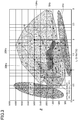
- In the first aspect, as illustrated in the graph of
FIG. 3 showing results of a vortex ring generation test, the Reynolds number Re and the L/D ratio are included in a range (A) satisfying relationships of 500 ≤ Re ≤ 3000 and 0.5 ≤ L/D ≤ 2.0. Thus, a stable vortex ring including almost no straight flow is generated. - A second aspect of the present disclosure is an embodiment of the first aspect. In the second aspect, relationships of 1000 ≤ Re ≤ 2500 and 0.75 ≤ L/D ≤ 2.0 are satisfied.
- In the second aspect, as illustrated in
FIG. 3 , the Reynolds number Re and the L/D ratio are included in a range (B) satisfying relationships of 1000 ≤ Re ≤ 2500 and 0.75 ≤ L/D ≤ 2.0. Thus, a vortex ring more stable than that in the range (A) is generated. - A third aspect of the present disclosure is an embodiment of the second aspect. In the third aspect, relationships of 1500 ≤ Re ≤ 2000 and 1.0 ≤ L/D ≤ 2.0 are satisfied.
- In the third aspect, as illustrated in
FIG. 3 , the Reynolds number Re and the L/D ratio are included in a range (C) satisfying relationships of 1500 ≤ Re ≤ 2000 and 1.0 ≤ L/D ≤ 2.0. Thus, a vortex ring even more stable than that in the range (B) is generated. - A fourth aspect of the present disclosure is an embodiment of any one of the first to third aspects. In the fourth aspect, when U represents a blow-out flow rate (m/s), relationships of 0.06 ≤ D ≤ 0.15, 0.12 ≤ L ≤ 0.3, and 0.3 ≤ U ≤ 0.75 are satisfied.
- In the fourth aspect, the Reynolds number Re and the L/D ratio are limited to any one of the ranges (A) to (C) of the first to third aspects. Then, the diameter D (mm) of the discharge port (25), the blow-out flow rate U (m/s), and the equivalent length L (mm) of the cylinder are set to the ranges described above. Further, the results of the vortex ring generation test in
FIG. 3 demonstrates that an outreach A (m) of the vortex ring is approximately proportional to the diameter D (m) of the discharge port (25), and the outreach A (m) of the vortex ring is about 2 m when D = 60 mm (0.06 m). The equivalent length L (m) of the cylinder and the blow-out flow rate U (m/s) are set to satisfy the diameter D (m) of 0.06 ≤ D ≤ 0.15. Therefore, setting the diameter D (m) of the discharge port (25) to 0.06 ≤ D ≤ 0.15 enables a stable vortex ring achieving an outreach A of 2 m ≤ A ≤ 5 (m) to be generated. -
-
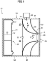
FIG. 1 is a schematic cross-sectional view of an internal structure of a vortex ring generation device according to an embodiment. -
FIG. 2A is a perspective view of an outlet diameter D and an extrusion volume V in the vortex ring generation device. -
FIG. 2B is a perspective view of a cylinder having the extrusion volume V and the outlet diameter D. -
FIG. 3 is a graph showing results of a vortex ring generation test performed using the vortex ring generation device under different conditions, where the vertical axis indicates the Reynolds number Re and the horizontal axis indicates the L/D ratio. - Hereinafter, embodiments will be described with reference to the drawings. The embodiments below are merely exemplary ones in nature, and are not intended to limit the scope, applications, or use of the present invention.
- A vortex ring generation device (10) according to an embodiment discharges vortex ring-shaped air (a vortex ring (R)). The vortex ring generation device (10) causes a predetermined discharge component to be contained in the vortex ring (R), and then supplies the vortex ring (R) containing the discharge component to, for example, a subject. The discharge component contains substances such as a scent component, water vapor, and a substance having predetermined efficacy. The discharge component is preferably a gas, but may be a liquid. In the case of liquid, the discharge component is preferably a particulate liquid.
- As illustrated in
FIG. 1 , the vortex ring generation device (10) includes: a casing (20) having a discharge port (25); an extrusion mechanism (30); a passage forming member (40); and a component supply device (50). An air passage (gas passage) (C) through which air flows is formed inside the casing (20). In the vortex ring generation device (10), the air in the air passage (C) is extruded by the extrusion mechanism (30), formed into the vortex ring (R), and discharged from the discharge port (25). The vortex ring (R) discharged from the discharge port (25) contains the discharge component supplied from the component supply device (50). - The casing (20) includes a casing body (21) having a front side open, and a substantially plate-like front panel (22) blocking the open face on the front side of the casing body (21). The casing (20) has a hollow cuboid shape. A middle portion of the front panel (22) has the discharge port (25) in the circular shape passing therethrough in a front-rear direction. A peripheral wall (23) in a substantially cylindrical shape continues on a rear surface of the front panel (22). The peripheral wall (23) extends rearward from an inner peripheral edge (26) of the discharge port (25). The peripheral wall (23) has a tapered shape whose diameter becomes smaller frontward. An outer peripheral end of the peripheral wall (23) is fixed to an inner wall of the casing body (21). A front leading end portion of the peripheral wall (23) is continuous with the inner peripheral edge (26) of the discharge port (25). An center axis of the peripheral wall (23) substantially coincides with that of the discharge port (25).
- The passage forming member (40) is disposed rearward of the peripheral wall (23). The passage forming member (40) is formed in a substantially cylindrical shape along an inner peripheral surface of the peripheral wall (23). The passage forming member (40) has a tapered shape whose diameter becomes smaller frontward (i.e., downstream of the air passage (C)). A center axis of the passage forming member (40) substantially coincides with that of the discharge port (25). The center axis of the passage forming member (40) substantially coincides with that of the peripheral wall (23).
- A component chamber (27) in which the discharge component is temporarily stored is defined in space surrounded by the inner wall of the casing body (21), the peripheral wall (23), and the passage forming member (40). The component chamber (27) is a substantially cylindrical space formed around the passage forming member (40).
- The extrusion mechanism (30) is disposed in the rearward inside the casing (20). The extrusion mechanism (30) has a vibration plate (31) that is a movable member, and a linear actuator (35) that displaces the vibration plate (31) back and forth. The vibration plate (31) includes a vibration plate body (32) and a frame-shaped elastic support (33) disposed at an outer peripheral edge of the vibration plate body (32). The vibration plate (31) is fixed to an inner wall of the casing (20) via the elastic support (33). The linear actuator (35) constitutes a drive unit that vibrates the vibration plate (31) back and forth. A base end (rear end) of the linear actuator (35) is supported by a rear wall of the casing body (21). A leading end (front end) of the linear actuator (35) is coupled with a center portion of the vibration plate (31).
- The linear actuator (35) vibrates the vibration plate (31) between a reference position and an extrusion position. Thus, the air (indicated by an open arrow in
FIG. 1 ) in the air passage (C) is extruded forward. - The air passage (C) extends from the vibration plate (31) to the discharge port (25) in the casing (20). The air passage (C) includes a first passage (C1) and a second passage (C2) continuous with a downstream end of the first passage (C1). The first passage (C1) is surrounded by the inner wall of the casing body (21). A passage area of the first passage (C1) is constant. The second passage (C2) is formed inside the passage forming member (40). Specifically, the second passage (C2) is surrounded by the peripheral wall (23). The second passage (C2) constitutes a throttle passage whose passage area becomes smaller toward its downstream. Thus, in the second passage (C2), the flow rate of air gradually increases toward its downstream.
- The component supply device (50) supplies, into the casing (20), the discharge component to be applied to the vortex ring (R). Specifically, the component supply device (50) supplies, via a supply passage (51), the predetermined discharge component to the component chamber (27) defined inside the casing (20). The component supply device (50) includes a component generation unit (not shown) that generates the discharge component and a conveyance unit (not shown) that conveys the discharge component generated in the generation unit. The component generation unit is, for example, of a vaporizing type that vaporizes the discharge component from a component raw material. The conveyance unit is, for example, an air pump. The component supply device (50) appropriately supplies, to the component chamber (27), the discharge component whose concentration has been adjusted to a predetermined concentration.
- The vortex ring generation device (10) has a component supply port (60) for supplying the discharge component to the air passage (C). In the present embodiment, the casing (20) has one component supply port (60). The component supply port (60) is located adjacent to the discharge port (25).
- More specifically, the component supply port (60) is disposed between a downstream end (41) of the passage forming member (40) in a cylinder axial direction and the inner peripheral edge (26) of the discharge port (25). Thus, one annular (strictly speaking, toric) component supply port (60) is formed around the downstream end of the air passage (C). Specifically, one annular component supply port (60) is formed near the discharge port (25) in the air passage (C).
- The basic operation of the vortex ring generation device (10) will be described with reference to
FIG. 1 . - When the vortex ring generation device is in operation, the linear actuator (35) vibrates the vibration plate (31). When the vibration plate (31) deforms forward, the volume of the air passage (C) decreases. As a result, the air in the air passage (C) flows toward the discharge port (25).
- The air in the first passage (C1) flows into the second passage (C2). In the second passage (C2), the passage area gradually decreases, so that the flow rate of air increases. When the flow rate of the air increases, the pressure of the air decreases. In particular, an outlet end of the second passage (C2) has the smallest passage area. Therefore, the flow rate of the air at the outlet end of the second passage (C2) is substantially the highest in the air passage (C). Consequently, the pressure of the air at the outlet end of the second passage (C2) is substantially the lowest.
- The component supply port (60) is located at the outlet end of the second passage (C2). Therefore, when the air at low pressure passes through the component supply port (60), the discharge component in the component chamber (27) is sucked into the air passage (C) due to the difference between the pressure of the air and the pressure in the component chamber (27). When the discharge component in the component chamber (27) is sucked into the air passage (C), the discharge component is dispersed in the air passing through the component supply port (60).
- The constant flow rate of the air passing through the component supply port (60) allows a constant amount of the discharge component to be sucked from the component supply port (60). This allows the concentrations of the discharge component in the air and the vortex ring (R) to be controlled to be constant.
- Since the component supply port (60) has an annular shape surrounding the air passage (C), the discharge component in the component chamber (27) is dispersed over the entire circumference of the air passage (C). Further, the discharge component is easily applied to the air flowing through the air passage (C), in particular, to the air near the outer periphery. This allows, in the air passage (C), the discharge component to be uniformly applied to the air near the outer periphery.
- In this way, the air containing the discharge component reaches the discharge port (25) immediately. The air passing through the discharge port (25) has a relatively high flow rate, whereas the air around the discharge port (25) is still. For this reason, a shearing force acts on the air at discontinuous planes of both air flows, and a vortex flow is generated adjacent to an outer peripheral edge of the discharge port (25). The vortex flow forms a vortex ring-shaped air (vortex ring (R) schematically shown in
FIG. 1 ) moving forward from the discharge port (25). The vortex ring (R) containing the discharge component is supplied to the subject. - As described above, the discharge component is supplied over the entire circumference of the air flow from the component supply port (60). Therefore, the discharge component is also dispersed in the vortex ring (R) circumferentially. This allows reduction in uneven distribution of the discharge component in the vortex ring (R). The discharge component is supplied from the component supply port (60), in particular, to the air at an outer peripheral side. This allows most of the discharge component in the component chamber (27) to be contained in the vortex ring (R).
- The component supply port (60) is located adjacent to the discharge port (25). If the component supply port (60) and the discharge port (25) are relatively far away from each other, the discharge component supplied into the air may diffuse before reaching the discharge port (25), and the amount of the discharge component contained in the vortex ring (R) may decrease. To address this problem, the component supply port (60) and the discharge port (25) are made close to each other, thereby allowing reduction in such diffusion of the discharge component.
- The component supply port (60) located adjacent to the discharge port (25) is located substantially at the most downstream end of the air passage (C). This allows a sufficient distance between the component supply port (60) and the extrusion mechanism (30) (strictly speaking, the vibration plate (31)) to be secured. This sufficient distance allows reduction in adhesion of the discharge component which has been supplied from the component supply port (60), to the extrusion mechanism (30) even if the air in the air passage (C) flows slightly backward due to the vibration of the vibration plate (31). This reduction allows avoidance of an increase in frequency of maintenance of the extrusion mechanism (30) and peripheral components thereof required due to adhesion of the discharge component, for example.
- Since the component supply port (60) is annular in shape, the flow rate of the air passing through the discharge port (25) is equalized circumferentially, as compared to a case in which the component supply port (60) is unevenly distributed circumferentially, for example. This allows the vortex ring (R) to be stably formed at the discharge port (25).
- A vortex ring generation test was conducted using the vortex ring generation device (10) of the present embodiment. In the vortex ring generation test, the casing (20) of the vortex ring generation device (10) was formed into a hollow cuboid having about 100 mm to about 150 mm sides, and the discharge port (25) had a diameter D of 30 mm, as shown in
FIGS. 2A and 2B . - The vortex ring generation test was performed at a plurality of different values of extrusion frequency f (vibration frequencies of the vibration plate (31)) of air, ranging from 2 Hz to 30 Hz. When, in addition to D (mm) representing the diameter of the discharge port (25), V (m3) represents an extrusion volume, L (mm) represents a length of the cylinder having the diameter D and the volume V (equivalent length of the cylinder), and U (m/s) represents an extrusion flow rate, the extrusion flow rate U varied within a range of 0.4 m/s to 3.2 m/s in response to the different values of extrusion frequency f. Further, the extrusion volume V ranged from 0.004 m3 to 0.65 m3, and the equivalent length L of the cylinder ranged from 6 mm to 92 mm (0.006 m to 0.092 m).
-
FIG. 3 is a graph plotting test results (values at measurement points) where the vertical axis represents the Reynolds number Re, and the horizontal axis represents the L/D ratio. In the graph ofFIG. 3 , representative values of the extrusion frequency f are indicated on the respective lines each of which is obtained by connecting plotted points of the same value of the extrusion frequency f. As can be seen from the representative values and the lines, the smaller the extrusion frequency f is, the smaller the Reynolds number Re is and the wider the L/D ratio range is (the smaller the line inclination angle is), whereas the larger the extrusion frequency f is, the wider the Reynolds number is and the smaller the L/D ratio range is (the larger the line inclination angle is). The Reynolds number Re is a value expressed by an equation Re = UD/v (v: coefficient of kinematic viscosity (m2/s)), and L/D is a value expressed by an equation UT/D (T: extrusion time (sec)). - When specific values of the Reynolds number Re, the L/D ratio, the extrusion frequency f, the flow rate U, the extrusion volume V, and the equivalent length L of the cylinder, at a point P shown in the graph are shown as the representative values, Re = 1865, L/D = 1.54, f = 10 Hz, U = 0.9 m/s, V = 0.33 m3, and L = 46.1 mm (0.0461 m).
-
FIG. 3 shows a region in which a vortex ring having an outreach A of 20 to 40 (cm) was generated, a region in which a vortex ring having an outreach A of 50 (cm) or more was generated, a region in which a vortex ring was generated, but diffused a little more, a region in which a vortex ring was not generated, and a region in which the vibration plate (31) (linear actuator (35)) could not be fully controlled. The region in which the vortex ring was not generated is a region in which the extrusion frequency f was low. The region in which the vibration plate (31) could not be fully controlled is a region in which the extrusion frequency was high. In the range of the extrusion frequency f from 5 to 30 (Hz), a vortex ring was substantially generated, although the outreach A and the extent of diffusion were different. - In the range (A) in which the Reynolds number Re and the L/D ratio satisfy relationships of 500 ≤ Re ≤ 3000 and 0.5 ≤ L/D ≤ 2.0 in
FIG. 3 , a straight flow was hardly generated in the vortex ring, and a stable vortex ring whose lingering was hardly observed was generated. In the graph, the outreach A of the vortex ring at a point Q where Re = 3000 and L/D = 2 was about 1 m. - In the range (B) in which the Reynolds number Re and the L/D ratio satisfy relationships of 1000 ≤ Re ≤ 2500 and 0.75 ≤ L/D ≤ 2.0, the straight flow generated was less than that in the range (A), and a more stable vortex ring was generated. The range (C) in which the Reynolds number Re and the L/D ratio satisfy relationships of 1500 ≤ Re ≤ 2000 and 1.0 ≤ L/D ≤ 2.0 substantially corresponds to the region in which the outreach A of the vortex ring was 50 (cm) or more, and the straight flow generated was less than that in the range (B), and a further stable vortex ring was generated.
- The above results show that the present embodiment allows only the vortex ring to be conveyed to a desired place without substantially generating a straight flow. Thus, the present embodiment allows the scent component not to be conveyed to an unintended place.
- Results of the test performed with the change in diameter of the discharge port (25) show that the outreach A (m) of the vortex ring increases approximately in proportion to the size of the diameter D (mm) of the discharge port (25). Therefore, when the test is performed under the same conditions as in Test Example 1 with the diameter D of the discharge port (25) set to 60 mm (0.06 m), the outreach A of the vortex ring at the point Q is about 2 m.
- The above-described vortex ring generation test showed that the diameter D (mm) of the discharge port (25) suitable for increasing the outreach A of the vortex ring, the blow-out flow rate U (m/s), and the equivalent length L (mm) of the cylinder were within the following ranges.
- The range of the diameter D of the discharge port (25): 60 mm ≤ D ≤ 150 mm (0.06 m ≤ D ≤ 0.15 m)
- The range of the blow-out flow rate U: 0.30 m/s ≤ U ≤ 0.75m/s
- The range of the equivalent length L of the cylinder was: 120 mm ≤ L ≤ 300 mm (0.12 m ≤ L ≤ 0.3 m)
- The extrusion time T was 0.16 ≤ T ≤ 0.99 (sec). At that time, the Reynolds number Re was Re = 3000 within the range (A) of 500 ≤ Re ≤ 3000, and the L/D ratio was L/D = 2.0 within the range (A) of the range of 0.5 ≤ L/D ≤ 2.0.
- Under the above-described conditions, a stable vortex ring having the outreach A of about 2 m was generated as described above. As described above, since the outreach A (m) of the vortex ring becomes longer in substantial proportion to the diameter D (mm) of the discharge port (25), a stable vortex ring having an outreach A of about 5 m can be generated at D = 150 mm. Further, the range of the blow-out flow rate U (m/s) and the range of the equivalent length L (m) of the cylinder correspond to the generation of a vortex ring having a long outreach A if the range of the diameter D is set to 60 mm ≤ D ≤ 150 mm.
- As described above, in Test Example 2 of the vortex ring generation test of the present embodiment, the Reynolds number Re and the L/D ratio were limited to the range (A), and the diameter D (mm) of the discharge port (25), the blow-out flow rate U (m/s), and the equivalent length L (mm) of the cylinder were set to the ranges described above. Thus, it was possible to generate the vortex ring achieving the outreach A of 2 m ≤ A ≤ 5 m.
- It has been difficult to generate a stable vortex ring by using a known vortex ring generation device. This is because, for example, the known vortex ring generation device requires the L/D ratio set to more than 2, which causes the vortex ring not to be stable and linger, and also requires the Reynolds number Re set to more than 3000, which causes the vortex to be turbulent and easily disappear due to its movement with dispersion.
- As can be seen from the test results of the vortex ring generation tests described above, in the present embodiment, setting the Reynolds number Re and the L/D ratio within the range (A) that satisfies the relationships of 500 ≤ Re ≤ 3000 and 0.5 ≤ L/D ≤ 2.0 allows a stable vortex ring including substantially no straight flow to be generated.
- Further, setting the Reynolds number Re and the L/D ratio within the range (B) satisfying the relationships of 1000 ≤ Re ≤ 2500 and 0.75 ≤ L/D ≤ 2.0 allows a vortex ring more stable than that in the range (A) to be generated.
- In addition, setting the Reynolds number Re and the L/D ratio within the range (C) satisfying the relationship of 1500 ≤ Re ≤ 2000 and 1.0 ≤ L/D ≤ 2.0 allows a vortex ring more stable than that in the range (B) to be generated.
- In particular, setting the diameter D (mm) of the discharge port (25), the blow-out flow rate U (m/s), and the equivalent length L (mm) of the cylinder to satisfy relationships of 0.06 ≤ D ≤ 0.15, 0.12 ≤ L ≤ 0.3, and 0.3 ≤ U ≤ 0.75 allows a stable vortex ring achieving an outreach A of 2 m ≤ A ≤ 5 m to be generated.
- As described above, the Reynolds number exceeding 3000 or being a large value such as 5000, 10000, or more causes diffusion of the vortex ring even if generated, and causes the vortex ring to be less likely to be generated. By contrast, in the present embodiment, the Reynolds number is limited to a relatively small range and the L/D ratio is also limited to a value suitable for this range of the Reynolds number, thereby allowing a prominent advantage of generating a stable vortex ring to be exhibited, as compared to the known device.
- Therefore, the present embodiment allows a stable vortex ring with almost no straight flow to be generated and to be conveyed to the intended place. This allows avoidance of the conveyance of the scent to the unintended places when the vortex ring containing the scent component is conveyed. As a result, the present embodiment enables avoidance of situations in which the scent remains in a wide range including a place to which the scent component is not intended to be conveyed, which causes the olfactory sense to be accustomed to the effect, or people who are in the place where the scent is not intended to be conveyed to feel discomfort.
- The above embodiment may also be configured as follows.
- For example, in the above embodiment, the range (A) satisfying the relationships of 500 ≤ Re ≤ 3000 and 0.5 ≤ L/D ≤ 2.0, the range (B) satisfying the relationships of 1000 ≤ Re ≤ 2500 and 0.75 ≤ L/D ≤ 2.0, and the range (C) satisfying the relationships of 1500 ≤ Re ≤ 2000 and 1.0 ≤ L/D ≤ 2.0 are described. However, the range may be suitably changed into any range as long as it does not exceed the range (A). For example, a range satisfying relationships of 1000 ≤ Re ≤ 2500 and 0.5 ≤ L/D ≤ 2.0 may be employed instead of the range (B), or a range satisfying relationships of 1500 ≤ Re ≤ 2000 and 0.5 ≤ L/D ≤ 2.0 may be employed instead of the range (C).
- In the above-described embodiment, the discharge component such as a scent component is contained in the vortex ring. However, in the vortex ring generation device of the present disclosure, the discharge component such as the scent component may not be included in the vortex ring.
- While the embodiments and variations thereof have been described above, various changes in form and details may be made without departing from the spirit and scope of the claims. The embodiments and the variations thereof may be combined and replaced with each other without deteriorating intended functions of the present disclosure.
- As described above, the present disclosure is useful for a vortex ring generation device.
-
- 10
- Vortex Ring Generation Device
- 20
- Casing
- 25
- Discharge Port
- 30
- Extrusion Mechanism
- C
- Air Passage (Gas Passage)
Claims (4)
- A vortex ring generation device comprising:a casing (20) having a gas passage (C) and a discharge port (25); andan extrusion mechanism (30) that extrudes a gas in the gas passage (C) such that the gas in a vortex ring shape is discharged from the discharge port (25), whereinwhen V (m3) represents an extrusion volume, D (m) represents a diameter of the discharge port (25), L (m) represents a length of a cylinder having the diameter D and the volume V, and Re represents a Reynolds number of the discharged gas, relationships of500 ≤ Re ≤ 3000 and0.5 ≤ L/D ≤ 2.0
are satisfied. - The vortex ring generation device of claim 1, wherein relationships of 1000 ≤ Re ≤ 2500 and 0.75 ≤ L/D ≤ 2.0 are satisfied.
- The vortex ring generation device of claim 2, wherein relationships of 1500 ≤ Re ≤ 2000 and 1.0 ≤ L/D ≤ 2.0 are satisfied.
- The vortex ring generation device of any one of claims 1 to 3, wherein
when U represents a blow-out flow rate (m/s), relationships of
0.06 ≤ D ≤ 0.15,
0.12 ≤ L ≤ 0.3, and
0.3 ≤ U ≤ 0.75
are satisfied.
Applications Claiming Priority (2)
| Application Number | Priority Date | Filing Date | Title |
|---|---|---|---|
| JP2018184721A JP6845835B2 (en) | 2018-09-28 | 2018-09-28 | Vortic ring generator |
| PCT/JP2019/037658 WO2020067190A1 (en) | 2018-09-28 | 2019-09-25 | Vortex ring generation device |
Publications (3)
| Publication Number | Publication Date |
|---|---|
| EP3832222A1 true EP3832222A1 (en) | 2021-06-09 |
| EP3832222A4 EP3832222A4 (en) | 2022-04-20 |
| EP3832222B1 EP3832222B1 (en) | 2025-07-30 |
Family
ID=69952893
Family Applications (1)
| Application Number | Title | Priority Date | Filing Date |
|---|---|---|---|
| EP19867031.7A Active EP3832222B1 (en) | 2018-09-28 | 2019-09-25 | Vortex ring generation device |
Country Status (5)
| Country | Link |
|---|---|
| US (1) | US11859646B2 (en) |
| EP (1) | EP3832222B1 (en) |
| JP (1) | JP6845835B2 (en) |
| CN (1) | CN112789454A (en) |
| WO (1) | WO2020067190A1 (en) |
Families Citing this family (2)
| Publication number | Priority date | Publication date | Assignee | Title |
|---|---|---|---|---|
| CN115560426A (en) * | 2021-07-01 | 2023-01-03 | 杭州气味王国科技有限公司 | scent delivery device |
| CN115364604A (en) * | 2022-08-29 | 2022-11-22 | 浙江省特种设备科学研究院 | A kind of vortex gun equipment for dust removal |
Family Cites Families (36)
| Publication number | Priority date | Publication date | Assignee | Title |
|---|---|---|---|---|
| US2855714A (en) * | 1955-10-17 | 1958-10-14 | William J Thomas | Smoke ring producing toy gun |
| US3940060A (en) * | 1974-08-23 | 1976-02-24 | Hermann Viets | Vortex ring generator |
| US4534914A (en) * | 1981-12-23 | 1985-08-13 | Nihon Sanso Kabushiki Kaisha | Method and apparatus for producing vortex rings of a gas in a liquid |
| US5052813A (en) * | 1988-11-08 | 1991-10-01 | Brian Latto | Tube type vortex ring mixers |
| US5181475A (en) * | 1992-02-03 | 1993-01-26 | Consolidated Natural Gas Service Company, Inc. | Apparatus and process for control of nitric oxide emissions from combustion devices using vortex rings and the like |
| US5483953A (en) * | 1995-04-08 | 1996-01-16 | The United States Of America As Represented By The Secretary Of The Navy | Aerosol dispensing apparatus for dispensing a medicated vapor into the lungs of a patient |
| US5823434A (en) * | 1997-05-05 | 1998-10-20 | The United States Of America As Represented By The Secretary Of The Navy | Electromechanical driver for an aerosol dispensing apparatus which dispenses a medicated vapor into the lungs of a patient |
| JP3675203B2 (en) * | 1998-12-14 | 2005-07-27 | 三菱電機株式会社 | Fluid transport device, humidifier using the fluid transport device, air conditioner, air condition system |
| FR2824626B1 (en) * | 2001-05-14 | 2004-04-16 | Pierre Bridenne | METHOD AND DEVICE FOR BROADCASTING A PROTECTIVE FLOW WITH REGARD TO AN ENVIRONMENT |
| JP2005513385A (en) * | 2002-01-03 | 2005-05-12 | パックス サイエンティフィック インコーポレイテッド | Vortex ring generator |
| US6848631B2 (en) * | 2002-01-23 | 2005-02-01 | Robert James Monson | Flat fan device |
| US6824125B2 (en) * | 2002-09-10 | 2004-11-30 | Andrew S. W. Thomas | Simple method for the controlled production of vortex ring bubbles of a gas in a liquid |
| US7300040B2 (en) * | 2004-12-23 | 2007-11-27 | Andrew Sydney Withiel Thomas | Simple, mechanism-free device, and method to produce vortex ring bubbles in liquids |
| JP2006282082A (en) * | 2005-04-01 | 2006-10-19 | Denso Corp | Air gun generator for vehicles |
| JP2006280748A (en) * | 2005-04-01 | 2006-10-19 | Denso Corp | Air quality component supply device for vehicles |
| JP4821467B2 (en) * | 2006-07-04 | 2011-11-24 | 株式会社デンソー | Air quality component supply device |
| US8523642B2 (en) * | 2006-03-03 | 2013-09-03 | Denso Corporation | Gaseous constituent supply device |
| JP2008018394A (en) * | 2006-07-14 | 2008-01-31 | Denso Corp | Air quality component supply device |
| JP2008275196A (en) * | 2007-04-25 | 2008-11-13 | Fuji Heavy Ind Ltd | Air gun |
| US20160045696A1 (en) * | 2007-11-27 | 2016-02-18 | Mapatunage A. Siriwardena | Toroidal ring ventilator |
| US20100303671A1 (en) * | 2009-05-31 | 2010-12-02 | Bertrand Jerome C | Hand cleansing/sanitizing method and apparatus |
| US8607774B2 (en) * | 2009-08-13 | 2013-12-17 | Jeffery M. Davis | Vortex ring producing gun |
| EP2743505B1 (en) * | 2011-06-20 | 2019-11-13 | Mitsubishi Electric Corporation | Fluid conveying device |
| US9092953B1 (en) * | 2012-01-24 | 2015-07-28 | Bruce J. P. Mortimer | System and method for providing a remote haptic stimulus |
| US20130214054A1 (en) * | 2012-02-09 | 2013-08-22 | Battelle Memorial Institute | Generator apparatus for producing vortex rings entrained with charged particles |
| CN104769367B (en) * | 2012-07-24 | 2017-10-13 | 赤木富士雄 | Fluid handling device and fluid handling method |
| JP6194145B2 (en) * | 2014-03-10 | 2017-09-06 | 株式会社豊田中央研究所 | Functional ingredient transport device |
| US20150328960A1 (en) * | 2014-05-15 | 2015-11-19 | GM Global Technology Operations LLC | Hvac vent utilizing vortex ring air flow |
| EP3148908B1 (en) * | 2014-05-27 | 2018-04-11 | OCE-Technologies B.V. | Air vortex assisted sheet flipping device |
| US9682388B2 (en) * | 2014-12-05 | 2017-06-20 | Elwha Llc | Using vortex rings to deliver gases at a distance |
| JP2017053592A (en) * | 2015-09-11 | 2017-03-16 | 株式会社九電工 | Vortex ring generator for air conditioning |
| JP2017198433A (en) * | 2016-04-29 | 2017-11-02 | 株式会社九電工 | Air vortex ring generator |
| JP2018110667A (en) * | 2017-01-10 | 2018-07-19 | 花王株式会社 | Vortex ring generator |
| JP6711383B2 (en) * | 2018-09-28 | 2020-06-17 | ダイキン工業株式会社 | Vortex ring generator |
| EP3842702B1 (en) * | 2018-10-12 | 2023-06-28 | Daikin Industries, Ltd. | Vortex ring generating device |
| WO2021251469A1 (en) * | 2020-06-10 | 2021-12-16 | ダイキン工業株式会社 | Vortex ring generation device |
-
2018
- 2018-09-28 JP JP2018184721A patent/JP6845835B2/en active Active
-
2019
- 2019-09-25 EP EP19867031.7A patent/EP3832222B1/en active Active
- 2019-09-25 CN CN201980063774.XA patent/CN112789454A/en active Pending
- 2019-09-25 WO PCT/JP2019/037658 patent/WO2020067190A1/en not_active Ceased
-
2021
- 2021-03-25 US US17/212,513 patent/US11859646B2/en active Active
Also Published As
| Publication number | Publication date |
|---|---|
| CN112789454A (en) | 2021-05-11 |
| JP2020049476A (en) | 2020-04-02 |
| US11859646B2 (en) | 2024-01-02 |
| JP6845835B2 (en) | 2021-03-24 |
| US20210207628A1 (en) | 2021-07-08 |
| EP3832222A4 (en) | 2022-04-20 |
| WO2020067190A1 (en) | 2020-04-02 |
| EP3832222B1 (en) | 2025-07-30 |
Similar Documents
| Publication | Publication Date | Title |
|---|---|---|
| US11333178B2 (en) | Vortex ring generation device | |
| US11859646B2 (en) | Vortex ring generation device | |
| KR960006214B1 (en) | In-line gas/liquid dispersion | |
| EP1844690A3 (en) | Foam soap generator | |
| EP3842702B1 (en) | Vortex ring generating device | |
| US6196525B1 (en) | Device and method for fluid aeration via gas forced through a liquid within an orifice of a pressure chamber | |
| EP3037730A3 (en) | Eductor fuel purging system for a turbomachine | |
| US9527094B1 (en) | Fluid dispersion assembly | |
| JP5143942B2 (en) | Refinement mixing equipment | |
| SG185633A1 (en) | Method and apparatus for creating cavitation for blending and emulsifying | |
| JPS5926348B2 (en) | Fluid atomization dispersion device | |
| JP2008086868A (en) | Microbubble generator | |
| JP2009247715A (en) | Foaming apparatus of fire extinguish foam | |
| JP2023000764A (en) | Vortex ring generator | |
| JP2016073939A (en) | Fine bubble generator | |
| WO2001000997A1 (en) | Foam generator | |
| JP2010022927A (en) | Miniaturizing-mixing device | |
| US10322383B2 (en) | Radial flow processor and method for using same | |
| JP4932812B2 (en) | Bubble fire extinguisher mixer | |
| RU2644860C1 (en) | Acoustic atomiser for spraying solutions | |
| JP2007029909A (en) | Emulsifying method and its device | |
| US10583449B1 (en) | Fluid dispersion assembly | |
| RU42189U1 (en) | LIQUID SPRAYING DEVICE | |
| RU2232305C2 (en) | Jet-type pump | |
| JP5405135B2 (en) | Mixing nozzle and mixing method |
Legal Events
| Date | Code | Title | Description |
|---|---|---|---|
| STAA | Information on the status of an ep patent application or granted ep patent |
Free format text: STATUS: THE INTERNATIONAL PUBLICATION HAS BEEN MADE |
|
| PUAI | Public reference made under article 153(3) epc to a published international application that has entered the european phase |
Free format text: ORIGINAL CODE: 0009012 |
|
| STAA | Information on the status of an ep patent application or granted ep patent |
Free format text: STATUS: REQUEST FOR EXAMINATION WAS MADE |
|
| 17P | Request for examination filed |
Effective date: 20210302 |
|
| AK | Designated contracting states |
Kind code of ref document: A1 Designated state(s): AL AT BE BG CH CY CZ DE DK EE ES FI FR GB GR HR HU IE IS IT LI LT LU LV MC MK MT NL NO PL PT RO RS SE SI SK SM TR |
|
| DAV | Request for validation of the european patent (deleted) | ||
| DAX | Request for extension of the european patent (deleted) | ||
| REG | Reference to a national code |
Ref country code: DE Ref legal event code: R079 Free format text: PREVIOUS MAIN CLASS: F24F0013060000 Ipc: F15D0001000000 Ref country code: DE Ref legal event code: R079 Ref document number: 602019073434 Country of ref document: DE Free format text: PREVIOUS MAIN CLASS: F24F0013060000 Ipc: F15D0001000000 |
|
| A4 | Supplementary search report drawn up and despatched |
Effective date: 20220322 |
|
| RIC1 | Information provided on ipc code assigned before grant |
Ipc: F24F 6/18 20060101ALI20220316BHEP Ipc: F24F 6/00 20060101ALI20220316BHEP Ipc: B05B 17/04 20060101ALI20220316BHEP Ipc: A61L 9/00 20060101ALI20220316BHEP Ipc: F24F 13/06 20060101ALI20220316BHEP Ipc: F15D 1/00 20060101AFI20220316BHEP |
|
| RAP3 | Party data changed (applicant data changed or rights of an application transferred) |
Owner name: DAIKIN INDUSTRIES, LTD. |
|
| P01 | Opt-out of the competence of the unified patent court (upc) registered |
Effective date: 20230525 |
|
| GRAP | Despatch of communication of intention to grant a patent |
Free format text: ORIGINAL CODE: EPIDOSNIGR1 |
|
| RIC1 | Information provided on ipc code assigned before grant |
Ipc: B05B 17/06 20060101ALI20250409BHEP Ipc: F15D 1/00 20060101AFI20250409BHEP |
|
| STAA | Information on the status of an ep patent application or granted ep patent |
Free format text: STATUS: GRANT OF PATENT IS INTENDED |
|
| INTG | Intention to grant announced |
Effective date: 20250515 |
|
| RIN1 | Information on inventor provided before grant (corrected) |
Inventor name: UENO, MIZUHO Inventor name: UDA, MASAFUMI Inventor name: IMAI, YOUSUKE Inventor name: EMURA, CHIE Inventor name: FUJII, CHIHO |
|
| GRAS | Grant fee paid |
Free format text: ORIGINAL CODE: EPIDOSNIGR3 |
|
| GRAA | (expected) grant |
Free format text: ORIGINAL CODE: 0009210 |
|
| STAA | Information on the status of an ep patent application or granted ep patent |
Free format text: STATUS: THE PATENT HAS BEEN GRANTED |
|
| AK | Designated contracting states |
Kind code of ref document: B1 Designated state(s): AL AT BE BG CH CY CZ DE DK EE ES FI FR GB GR HR HU IE IS IT LI LT LU LV MC MK MT NL NO PL PT RO RS SE SI SK SM TR |
|
| REG | Reference to a national code |
Ref country code: GB Ref legal event code: FG4D |
|
| REG | Reference to a national code |
Ref country code: CH Ref legal event code: EP |
|
| REG | Reference to a national code |
Ref country code: DE Ref legal event code: R096 Ref document number: 602019073434 Country of ref document: DE |
|
| REG | Reference to a national code |
Ref country code: IE Ref legal event code: FG4D |
|
| PGFP | Annual fee paid to national office [announced via postgrant information from national office to epo] |
Ref country code: DE Payment date: 20250919 Year of fee payment: 7 |
|
| PGFP | Annual fee paid to national office [announced via postgrant information from national office to epo] |
Ref country code: GB Payment date: 20250919 Year of fee payment: 7 |
|
| PGFP | Annual fee paid to national office [announced via postgrant information from national office to epo] |
Ref country code: FR Payment date: 20250922 Year of fee payment: 7 |
|
| REG | Reference to a national code |
Ref country code: NL Ref legal event code: MP Effective date: 20250730 |
|
| REG | Reference to a national code |
Ref country code: AT Ref legal event code: MK05 Ref document number: 1819196 Country of ref document: AT Kind code of ref document: T Effective date: 20250730 |
|
| PG25 | Lapsed in a contracting state [announced via postgrant information from national office to epo] |
Ref country code: PT Free format text: LAPSE BECAUSE OF FAILURE TO SUBMIT A TRANSLATION OF THE DESCRIPTION OR TO PAY THE FEE WITHIN THE PRESCRIBED TIME-LIMIT Effective date: 20251202 |
|
| PG25 | Lapsed in a contracting state [announced via postgrant information from national office to epo] |
Ref country code: IS Free format text: LAPSE BECAUSE OF FAILURE TO SUBMIT A TRANSLATION OF THE DESCRIPTION OR TO PAY THE FEE WITHIN THE PRESCRIBED TIME-LIMIT Effective date: 20251130 |
|
| PG25 | Lapsed in a contracting state [announced via postgrant information from national office to epo] |
Ref country code: NO Free format text: LAPSE BECAUSE OF FAILURE TO SUBMIT A TRANSLATION OF THE DESCRIPTION OR TO PAY THE FEE WITHIN THE PRESCRIBED TIME-LIMIT Effective date: 20251030 |
|
| REG | Reference to a national code |
Ref country code: LT Ref legal event code: MG9D |
|
| PG25 | Lapsed in a contracting state [announced via postgrant information from national office to epo] |
Ref country code: AT Free format text: LAPSE BECAUSE OF FAILURE TO SUBMIT A TRANSLATION OF THE DESCRIPTION OR TO PAY THE FEE WITHIN THE PRESCRIBED TIME-LIMIT Effective date: 20250730 |
|
| PG25 | Lapsed in a contracting state [announced via postgrant information from national office to epo] |
Ref country code: FI Free format text: LAPSE BECAUSE OF FAILURE TO SUBMIT A TRANSLATION OF THE DESCRIPTION OR TO PAY THE FEE WITHIN THE PRESCRIBED TIME-LIMIT Effective date: 20250730 |
|
| PG25 | Lapsed in a contracting state [announced via postgrant information from national office to epo] |
Ref country code: HR Free format text: LAPSE BECAUSE OF FAILURE TO SUBMIT A TRANSLATION OF THE DESCRIPTION OR TO PAY THE FEE WITHIN THE PRESCRIBED TIME-LIMIT Effective date: 20250730 Ref country code: NL Free format text: LAPSE BECAUSE OF FAILURE TO SUBMIT A TRANSLATION OF THE DESCRIPTION OR TO PAY THE FEE WITHIN THE PRESCRIBED TIME-LIMIT Effective date: 20250730 |
|
| PG25 | Lapsed in a contracting state [announced via postgrant information from national office to epo] |
Ref country code: GR Free format text: LAPSE BECAUSE OF FAILURE TO SUBMIT A TRANSLATION OF THE DESCRIPTION OR TO PAY THE FEE WITHIN THE PRESCRIBED TIME-LIMIT Effective date: 20251031 |
|
| PG25 | Lapsed in a contracting state [announced via postgrant information from national office to epo] |
Ref country code: SE Free format text: LAPSE BECAUSE OF FAILURE TO SUBMIT A TRANSLATION OF THE DESCRIPTION OR TO PAY THE FEE WITHIN THE PRESCRIBED TIME-LIMIT Effective date: 20250730 |
|
| PG25 | Lapsed in a contracting state [announced via postgrant information from national office to epo] |
Ref country code: LV Free format text: LAPSE BECAUSE OF FAILURE TO SUBMIT A TRANSLATION OF THE DESCRIPTION OR TO PAY THE FEE WITHIN THE PRESCRIBED TIME-LIMIT Effective date: 20250730 |
|
| PG25 | Lapsed in a contracting state [announced via postgrant information from national office to epo] |
Ref country code: BG Free format text: LAPSE BECAUSE OF FAILURE TO SUBMIT A TRANSLATION OF THE DESCRIPTION OR TO PAY THE FEE WITHIN THE PRESCRIBED TIME-LIMIT Effective date: 20250730 Ref country code: PL Free format text: LAPSE BECAUSE OF FAILURE TO SUBMIT A TRANSLATION OF THE DESCRIPTION OR TO PAY THE FEE WITHIN THE PRESCRIBED TIME-LIMIT Effective date: 20250730 |
|
| PG25 | Lapsed in a contracting state [announced via postgrant information from national office to epo] |
Ref country code: RS Free format text: LAPSE BECAUSE OF FAILURE TO SUBMIT A TRANSLATION OF THE DESCRIPTION OR TO PAY THE FEE WITHIN THE PRESCRIBED TIME-LIMIT Effective date: 20251030 |
|
| PG25 | Lapsed in a contracting state [announced via postgrant information from national office to epo] |
Ref country code: ES Free format text: LAPSE BECAUSE OF FAILURE TO SUBMIT A TRANSLATION OF THE DESCRIPTION OR TO PAY THE FEE WITHIN THE PRESCRIBED TIME-LIMIT Effective date: 20250730 |
|
| PG25 | Lapsed in a contracting state [announced via postgrant information from national office to epo] |
Ref country code: RO Free format text: LAPSE BECAUSE OF FAILURE TO SUBMIT A TRANSLATION OF THE DESCRIPTION OR TO PAY THE FEE WITHIN THE PRESCRIBED TIME-LIMIT Effective date: 20250730 |
|
| PG25 | Lapsed in a contracting state [announced via postgrant information from national office to epo] |
Ref country code: SM Free format text: LAPSE BECAUSE OF FAILURE TO SUBMIT A TRANSLATION OF THE DESCRIPTION OR TO PAY THE FEE WITHIN THE PRESCRIBED TIME-LIMIT Effective date: 20250730 |
|
| PG25 | Lapsed in a contracting state [announced via postgrant information from national office to epo] |
Ref country code: DK Free format text: LAPSE BECAUSE OF FAILURE TO SUBMIT A TRANSLATION OF THE DESCRIPTION OR TO PAY THE FEE WITHIN THE PRESCRIBED TIME-LIMIT Effective date: 20250730 |
|
| PG25 | Lapsed in a contracting state [announced via postgrant information from national office to epo] |
Ref country code: IT Free format text: LAPSE BECAUSE OF FAILURE TO SUBMIT A TRANSLATION OF THE DESCRIPTION OR TO PAY THE FEE WITHIN THE PRESCRIBED TIME-LIMIT Effective date: 20250730 |
|
| PG25 | Lapsed in a contracting state [announced via postgrant information from national office to epo] |
Ref country code: CZ Free format text: LAPSE BECAUSE OF FAILURE TO SUBMIT A TRANSLATION OF THE DESCRIPTION OR TO PAY THE FEE WITHIN THE PRESCRIBED TIME-LIMIT Effective date: 20250730 |
|
| PG25 | Lapsed in a contracting state [announced via postgrant information from national office to epo] |
Ref country code: SK Free format text: LAPSE BECAUSE OF FAILURE TO SUBMIT A TRANSLATION OF THE DESCRIPTION OR TO PAY THE FEE WITHIN THE PRESCRIBED TIME-LIMIT Effective date: 20250730 Ref country code: EE Free format text: LAPSE BECAUSE OF FAILURE TO SUBMIT A TRANSLATION OF THE DESCRIPTION OR TO PAY THE FEE WITHIN THE PRESCRIBED TIME-LIMIT Effective date: 20250730 |
|
| REG | Reference to a national code |
Ref country code: DE Ref legal event code: R097 Ref document number: 602019073434 Country of ref document: DE |
|
| REG | Reference to a national code |
Ref country code: CH Ref legal event code: H13 Free format text: ST27 STATUS EVENT CODE: U-0-0-H10-H13 (AS PROVIDED BY THE NATIONAL OFFICE) Effective date: 20260504 |
|
| PG25 | Lapsed in a contracting state [announced via postgrant information from national office to epo] |
Ref country code: LU Free format text: LAPSE BECAUSE OF NON-PAYMENT OF DUE FEES Effective date: 20250925 |
|
| REG | Reference to a national code |
Ref country code: BE Ref legal event code: MM Effective date: 20250930 |
|
| PLBE | No opposition filed within time limit |
Free format text: ORIGINAL CODE: 0009261 |
|
| STAA | Information on the status of an ep patent application or granted ep patent |
Free format text: STATUS: NO OPPOSITION FILED WITHIN TIME LIMIT |
|
| REG | Reference to a national code |
Ref country code: CH Ref legal event code: L10 Free format text: ST27 STATUS EVENT CODE: U-0-0-L10-L00 (AS PROVIDED BY THE NATIONAL OFFICE) Effective date: 20260611 |
|
| PG25 | Lapsed in a contracting state [announced via postgrant information from national office to epo] |
Ref country code: MC Free format text: LAPSE BECAUSE OF FAILURE TO SUBMIT A TRANSLATION OF THE DESCRIPTION OR TO PAY THE FEE WITHIN THE PRESCRIBED TIME-LIMIT Effective date: 20250730 Ref country code: LT Free format text: LAPSE BECAUSE OF FAILURE TO SUBMIT A TRANSLATION OF THE DESCRIPTION OR TO PAY THE FEE WITHIN THE PRESCRIBED TIME-LIMIT Effective date: 20250730 |
|
| 26N | No opposition filed |
Effective date: 20260501 |
|
| PG25 | Lapsed in a contracting state [announced via postgrant information from national office to epo] |
Ref country code: CH Free format text: LAPSE BECAUSE OF NON-PAYMENT OF DUE FEES Effective date: 20250930 Ref country code: IE Free format text: LAPSE BECAUSE OF NON-PAYMENT OF DUE FEES Effective date: 20250925 Ref country code: BE Free format text: LAPSE BECAUSE OF NON-PAYMENT OF DUE FEES Effective date: 20250930 |