EP3832165B1 - Système d'entraînement pour un véhicule doté d'un engrenage d'entraînement et architecture de commande permettant de commander l'engrenage d'entraînement - Google Patents
Système d'entraînement pour un véhicule doté d'un engrenage d'entraînement et architecture de commande permettant de commander l'engrenage d'entraînement Download PDFInfo
- Publication number
- EP3832165B1 EP3832165B1 EP20209663.2A EP20209663A EP3832165B1 EP 3832165 B1 EP3832165 B1 EP 3832165B1 EP 20209663 A EP20209663 A EP 20209663A EP 3832165 B1 EP3832165 B1 EP 3832165B1
- Authority
- EP
- European Patent Office
- Prior art keywords
- hydraulic motor
- hydraulic
- transmission
- speed
- driving
- Prior art date
- Legal status (The legal status is an assumption and is not a legal conclusion. Google has not performed a legal analysis and makes no representation as to the accuracy of the status listed.)
- Active
Links
- 230000005540 biological transmission Effects 0.000 title claims description 80
- 230000008859 change Effects 0.000 claims description 27
- 230000009347 mechanical transmission Effects 0.000 claims description 24
- 230000002706 hydrostatic effect Effects 0.000 claims description 21
- 238000006073 displacement reaction Methods 0.000 description 32
- 238000010586 diagram Methods 0.000 description 23
- 230000007704 transition Effects 0.000 description 7
- 238000013461 design Methods 0.000 description 5
- 238000000034 method Methods 0.000 description 4
- 238000013519 translation Methods 0.000 description 4
- 238000002485 combustion reaction Methods 0.000 description 3
- 230000008878 coupling Effects 0.000 description 3
- 238000010168 coupling process Methods 0.000 description 3
- 238000005859 coupling reaction Methods 0.000 description 3
- 230000008569 process Effects 0.000 description 3
- 230000001360 synchronised effect Effects 0.000 description 3
- 230000008901 benefit Effects 0.000 description 2
- 230000036461 convulsion Effects 0.000 description 2
- 238000007726 management method Methods 0.000 description 2
- 238000011161 development Methods 0.000 description 1
- 230000009977 dual effect Effects 0.000 description 1
- 239000012530 fluid Substances 0.000 description 1
- ZZUFCTLCJUWOSV-UHFFFAOYSA-N furosemide Chemical compound C1=C(Cl)C(S(=O)(=O)N)=CC(C(O)=O)=C1NCC1=CC=CO1 ZZUFCTLCJUWOSV-UHFFFAOYSA-N 0.000 description 1
- 239000011159 matrix material Substances 0.000 description 1
- 238000005457 optimization Methods 0.000 description 1
- 239000013589 supplement Substances 0.000 description 1
- 238000012549 training Methods 0.000 description 1
Images


Classifications
-
- F—MECHANICAL ENGINEERING; LIGHTING; HEATING; WEAPONS; BLASTING
- F16—ENGINEERING ELEMENTS AND UNITS; GENERAL MEASURES FOR PRODUCING AND MAINTAINING EFFECTIVE FUNCTIONING OF MACHINES OR INSTALLATIONS; THERMAL INSULATION IN GENERAL
- F16H—GEARING
- F16H61/00—Control functions within control units of change-speed- or reversing-gearings for conveying rotary motion ; Control of exclusively fluid gearing, friction gearing, gearings with endless flexible members or other particular types of gearing
- F16H61/38—Control of exclusively fluid gearing
- F16H61/40—Control of exclusively fluid gearing hydrostatic
- F16H61/46—Automatic regulation in accordance with output requirements
- F16H61/472—Automatic regulation in accordance with output requirements for achieving a target output torque
-
- F—MECHANICAL ENGINEERING; LIGHTING; HEATING; WEAPONS; BLASTING
- F16—ENGINEERING ELEMENTS AND UNITS; GENERAL MEASURES FOR PRODUCING AND MAINTAINING EFFECTIVE FUNCTIONING OF MACHINES OR INSTALLATIONS; THERMAL INSULATION IN GENERAL
- F16H—GEARING
- F16H47/00—Combinations of mechanical gearing with fluid clutches or fluid gearing
- F16H47/02—Combinations of mechanical gearing with fluid clutches or fluid gearing the fluid gearing being of the volumetric type
-
- F—MECHANICAL ENGINEERING; LIGHTING; HEATING; WEAPONS; BLASTING
- F16—ENGINEERING ELEMENTS AND UNITS; GENERAL MEASURES FOR PRODUCING AND MAINTAINING EFFECTIVE FUNCTIONING OF MACHINES OR INSTALLATIONS; THERMAL INSULATION IN GENERAL
- F16H—GEARING
- F16H61/00—Control functions within control units of change-speed- or reversing-gearings for conveying rotary motion ; Control of exclusively fluid gearing, friction gearing, gearings with endless flexible members or other particular types of gearing
- F16H61/04—Smoothing ratio shift
-
- F—MECHANICAL ENGINEERING; LIGHTING; HEATING; WEAPONS; BLASTING
- F16—ENGINEERING ELEMENTS AND UNITS; GENERAL MEASURES FOR PRODUCING AND MAINTAINING EFFECTIVE FUNCTIONING OF MACHINES OR INSTALLATIONS; THERMAL INSULATION IN GENERAL
- F16H—GEARING
- F16H61/00—Control functions within control units of change-speed- or reversing-gearings for conveying rotary motion ; Control of exclusively fluid gearing, friction gearing, gearings with endless flexible members or other particular types of gearing
- F16H61/38—Control of exclusively fluid gearing
- F16H61/40—Control of exclusively fluid gearing hydrostatic
- F16H61/42—Control of exclusively fluid gearing hydrostatic involving adjustment of a pump or motor with adjustable output or capacity
-
- F—MECHANICAL ENGINEERING; LIGHTING; HEATING; WEAPONS; BLASTING
- F16—ENGINEERING ELEMENTS AND UNITS; GENERAL MEASURES FOR PRODUCING AND MAINTAINING EFFECTIVE FUNCTIONING OF MACHINES OR INSTALLATIONS; THERMAL INSULATION IN GENERAL
- F16H—GEARING
- F16H61/00—Control functions within control units of change-speed- or reversing-gearings for conveying rotary motion ; Control of exclusively fluid gearing, friction gearing, gearings with endless flexible members or other particular types of gearing
- F16H61/38—Control of exclusively fluid gearing
- F16H61/40—Control of exclusively fluid gearing hydrostatic
- F16H61/44—Control of exclusively fluid gearing hydrostatic with more than one pump or motor in operation
- F16H61/444—Control of exclusively fluid gearing hydrostatic with more than one pump or motor in operation by changing the number of pump or motor units in operation
-
- F—MECHANICAL ENGINEERING; LIGHTING; HEATING; WEAPONS; BLASTING
- F16—ENGINEERING ELEMENTS AND UNITS; GENERAL MEASURES FOR PRODUCING AND MAINTAINING EFFECTIVE FUNCTIONING OF MACHINES OR INSTALLATIONS; THERMAL INSULATION IN GENERAL
- F16H—GEARING
- F16H61/00—Control functions within control units of change-speed- or reversing-gearings for conveying rotary motion ; Control of exclusively fluid gearing, friction gearing, gearings with endless flexible members or other particular types of gearing
- F16H61/70—Control functions within control units of change-speed- or reversing-gearings for conveying rotary motion ; Control of exclusively fluid gearing, friction gearing, gearings with endless flexible members or other particular types of gearing specially adapted for change-speed gearing in group arrangement, i.e. with separate change-speed gear trains arranged in series, e.g. range or overdrive-type gearing arrangements
- F16H61/702—Control functions within control units of change-speed- or reversing-gearings for conveying rotary motion ; Control of exclusively fluid gearing, friction gearing, gearings with endless flexible members or other particular types of gearing specially adapted for change-speed gearing in group arrangement, i.e. with separate change-speed gear trains arranged in series, e.g. range or overdrive-type gearing arrangements using electric or electrohydraulic control means
-
- F—MECHANICAL ENGINEERING; LIGHTING; HEATING; WEAPONS; BLASTING
- F16—ENGINEERING ELEMENTS AND UNITS; GENERAL MEASURES FOR PRODUCING AND MAINTAINING EFFECTIVE FUNCTIONING OF MACHINES OR INSTALLATIONS; THERMAL INSULATION IN GENERAL
- F16H—GEARING
- F16H59/00—Control inputs to control units of change-speed-, or reversing-gearings for conveying rotary motion
- F16H59/68—Inputs being a function of gearing status
- F16H2059/6838—Sensing gearing status of hydrostatic transmissions
- F16H2059/6861—Sensing gearing status of hydrostatic transmissions the pressures, e.g. high, low or differential pressures
-
- F—MECHANICAL ENGINEERING; LIGHTING; HEATING; WEAPONS; BLASTING
- F16—ENGINEERING ELEMENTS AND UNITS; GENERAL MEASURES FOR PRODUCING AND MAINTAINING EFFECTIVE FUNCTIONING OF MACHINES OR INSTALLATIONS; THERMAL INSULATION IN GENERAL
- F16H—GEARING
- F16H59/00—Control inputs to control units of change-speed-, or reversing-gearings for conveying rotary motion
- F16H59/68—Inputs being a function of gearing status
- F16H2059/6838—Sensing gearing status of hydrostatic transmissions
- F16H2059/6892—Sensing or calculating the motor torque
-
- F—MECHANICAL ENGINEERING; LIGHTING; HEATING; WEAPONS; BLASTING
- F16—ENGINEERING ELEMENTS AND UNITS; GENERAL MEASURES FOR PRODUCING AND MAINTAINING EFFECTIVE FUNCTIONING OF MACHINES OR INSTALLATIONS; THERMAL INSULATION IN GENERAL
- F16H—GEARING
- F16H59/00—Control inputs to control units of change-speed-, or reversing-gearings for conveying rotary motion
- F16H59/14—Inputs being a function of torque or torque demand
- F16H59/18—Inputs being a function of torque or torque demand dependent on the position of the accelerator pedal
-
- F—MECHANICAL ENGINEERING; LIGHTING; HEATING; WEAPONS; BLASTING
- F16—ENGINEERING ELEMENTS AND UNITS; GENERAL MEASURES FOR PRODUCING AND MAINTAINING EFFECTIVE FUNCTIONING OF MACHINES OR INSTALLATIONS; THERMAL INSULATION IN GENERAL
- F16H—GEARING
- F16H59/00—Control inputs to control units of change-speed-, or reversing-gearings for conveying rotary motion
- F16H59/36—Inputs being a function of speed
- F16H59/44—Inputs being a function of speed dependent on machine speed of the machine, e.g. the vehicle
Definitions
- the invention relates to a travel drive for a vehicle with a drive transmission which enables driving in several driving ranges and in which a mechanical transmission is combined with a hydrostatic transmission which includes a hydraulic pump whose displacement volume can be adjusted and at least one hydraulic motor which is connected to the hydraulic pump a closed hydraulic circuit with two circuit branches and is connected to an input of the mechanical transmission.
- the traction drive also includes an electronic control unit for carrying out traction-based control of the traction transmission.
- a hydrostatic transmission with a hydraulic pump and a hydraulic motor which are arranged together in a closed hydraulic circuit
- a mechanical transmission brings with it a high system efficiency and a wide usability of mobile work machines.
- Possible mechanical transmissions are synchronized transmissions with two or more gear stages, summation transmissions, which have two or more gear stages and which have driving ranges in which different numbers of hydraulic motors, for example a first hydraulic motor in a first driving range and a second in addition to the first hydraulic motor Hydraulic motor in a second driving range, to which the transmission output is connected, and powershift transmission.
- a drive transmission of the type outlined the travel drive of a mobile machine can be designed in such a way that torque-based control or speed-based control is possible.
- EP 3 553 347 A1 relates to a method for controlling a hydraulically driven work machine, wherein a target traction force at standstill, which corresponds to a leakage flow rate, is used to control a hydraulic pump, a hydraulic motor and an internal combustion engine.
- the invention is based on the object of designing a travel drive with the features mentioned at the outset in such a way that the driving behavior when changing gears is improved.
- This object is achieved in that the vehicle parameters present before a change in the driving range are used by the electronic control unit to determine the target tractive force desired after the change in the driving range and, from the desired target tractive force and a displacement volume of the at least one hydraulic motor, a target pressure difference between the two circuit branches of the closed hydraulic circuit is determined and that after changing the driving range between the two circuit branches of the closed hydraulic circuit, a pressure difference corresponding to the target pressure difference is set by a pressure regulator.
- a travel drive according to the invention does not have the problem described because of the adjustable tractive force after changing gear. This makes the drive much easier to calibrate. The quality of a gear change and thus driving comfort are improved. Almost every gear change takes place with a very small bandwidth in a very short time.
- a travel drive according to the invention can be further developed in an advantageous manner.
- the driving behavior appears particularly comfortable when the desired target tractive force is equal to the tractive force before changing the driving range.
- the desired target tractive force can be determined using only the position of the accelerator pedal. However, the speed of the vehicle can also be taken into account when determining the desired target tractive force. Assuming that the vehicle speed after shifting is similar to the vehicle speed before shifting, the pulling force before and after shifting should also be the same.
- ⁇ m the minimum of the two values n p V p /n m V m and 1, where n p is the speed of the hydraulic pump, n m is the speed of the hydraulic motor, V p that is the maximum displacement of the hydraulic pump and V m is the maximum displacement of the hydraulic motor or motors.
- ⁇ m is therefore equal to n p V p /n m V m or equal to 1, whichever is smaller.
- the speed of the hydraulic motor can also be determined from the speed of the vehicle.
- Mechanical gears are known that are designed as mere summation gears. Different driving ranges are realized here in that different numbers of hydraulic motors are connected to the output of the mechanical transmission in the driving ranges. For example, in a first driving range, two hydraulic motors are connected to the transmission output, while in a second driving range, only one hydraulic motor is connected to the transmission output.
- the invention can be applied both to driving gears with such summation gears and to driving gears which have a mechanical gear with at least two gear stages and in which a change is made from one gear stage to another gear stage when the driving range is changed.
- the electronic control unit of a travel drive advantageously has a control architecture which comprises a general part, which is programmed in the same way for at least two differently designed travel gears, and several different special parts, each of which can be connected to the general part via an interface and corresponding to the specific one Training of a driving gear is programmed.
- Such a control architecture advantageously also includes a drive transmission, which includes a hydrostatic transmission with a hydraulic pump and a hydraulic motor, but no mechanical transmission downstream of the hydraulic motor.
- a drive transmission which includes a hydrostatic transmission with a hydraulic pump and a hydraulic motor, but no mechanical transmission downstream of the hydraulic motor.
- a transmission with a mere hydrostatic transmission is also a special part for a transmission with a mere hydrostatic transmission.
- the several different specific parts each have the same interface for connection to the general part.
- the driving gear enables driving in several driving ranges, it is advantageous if the general part is suitably programmed to control the driving gear when driving within a driving range, and if the special part is suitably programmed to control the driving gear during a change between two to control driving areas.
- the special part can work in such a way that the control signals of the general part are overwritten by the special part.
- the general part of the control architecture contains equations for calculating the displacement of the hydraulic motor or hydraulic motors and for calculating the pressure difference across the hydraulic motor or hydraulic motors, the equations having terms for different transmissions, which are determined by factors that depend on the design of the Drive gear have the value zero or one, activated or deactivated.
- the control architecture is preferably designed for torque-based control of the driving gear.
- control architecture for the electronic control unit will appear less in the mechanical structure of the control unit than in the software, which contains a general program or several general programs that are applicable to differently designed travel drives and represent the general part of the control architecture, which depends on the type of the transmission is supplemented by one or more special programs that supplement the general program at one or more interfaces.
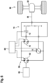
- the electronic control 15 is intended for a travel drive in which a hydrostatic transmission with two gear stages is combined with a hydraulic pump and with a hydraulic motor operated with the hydraulic pump in a closed hydraulic circuit.
- the hydraulic pump and the hydraulic motor are fluidly connected to one another via two circuit branches.
- a control section 20 of the electronic control 15 can be referred to as a shift manager, in which it is determined from the current vehicle state whether a gear change needs to take place and from which a gear change is initiated and controlled if necessary.
- the translation i mech of the mechanical transmission is thus determined by the control section 20 and is output by it as an output signal.
- the electronic control according to Figure 1 also has a control section 21, to which the speed v veh of the vehicle and the angular position ⁇ ped of the accelerator pedal are supplied as input variables and which, from these input variables present before a change, determines the target tractive force or the desired target torque T on the vehicle wheels after changing the driving range determined and can therefore be referred to as a tractive force planner or target torque planner.
- the speed n m of the hydraulic motor is supplied to a further control section 22 of the electronic control 15. This can either be measured or derived from the speed of the vehicle.
- the hydraulic pump and the hydraulic motor are usually axial piston machines and the standardized stroke volume is determined by the swivel angle, which is why the formula symbol ⁇ is used here.
- the pivot angle desired for the hydraulic motor after a gear change, the target torque T des desired after a gear change and the mechanical translation i mech after the gear change are supplied as electronic signals to a control section 23 of the electronic control 15, which calculates a desired pressure difference ⁇ p des from the values supplied determined that should exist after changing gear via the hydraulic motor.
- the desired pressure difference is sent to a pressure control device 24, which adjusts the pivot angle of the hydraulic pump so that the desired pressure difference is present via the hydraulic motor.
- the actual value of the pressure difference can be detected, for example, from the signals from two pressure sensors, one of which detects the pressure in one circuit branch and the other detects the pressure in the other circuit branch.
- the pressure difference can also be specified by a control pressure acting on an actuating piston of the hydraulic pump, which is set, for example, with a pressure control valve, and thus by a force resulting on the actuating piston.
- a hydrostatic transmission can be combined with different types of mechanical transmissions. It is a great advantage if travel drives with different mechanical transmissions can be controlled with just one software platform. Development time and costs are then saved.
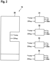
- the control architecture of such a software platform is in Figure 2 shown. It has a general part 30, which is programmed in the same way for at least two differently designed driving gears and is designed in such a way that it contains the temporary control variables ⁇ m,tmp and ⁇ p tmp , i.e. a temporary swivel angle of the hydraulic motor and a temporary pressure difference during normal driving outputs a driving range.
- the control architecture includes several different special parts 31, 32, 33, 34, each of which can be connected to the general part via the same interface and is programmed according to the specific design of a travel transmission.
- a special part is intended to output transmission-specific control variables ⁇ m and ⁇ p and information (state) about the status of the transmission during a change of a driving range, in particular during a change of the gear stage of the mechanical transmission.
- the special parts overwrite the output signals of the general part.
- the special parts of the transmission control can be adapted to other types of transmission controls in addition to a general part designed for torque control. With other types of transmission controls, the control architecture can also be divided into a general part and special parts.
- control architecture Another advantage of the control architecture is that optimizations made to one traction drive can easily be transferred to other types of traction drives.
- third-party software can be combined with the general part of the control architecture without requiring in-depth knowledge of the control of a hydrostatic transmission contained in the general part.
- the special part 31 according to Figure 2 is intended for summation transmissions, the special part 32 for synchronous transmissions, the special part 33 for powershift transmissions and the special part for purely hydrostatic transmissions.
- the temporary control variables ⁇ m,tmp and ⁇ p tmp pass from the general part 30 to the special part and are overwritten there.
- synchronous transmissions require a torque-free input shaft during the synchronization phase, which is not necessary for other types of mechanical transmissions.
- the special part 32 guarantees this freedom from torque by overwriting the swivel angle ⁇ m,tmp for the hydraulic motor and the desired pressure difference ⁇ p tmp .
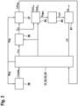
- a special part is designated 31, 32, 33, 34. This is supplied with the signal for the provisional desired pivot angle ⁇ m,tmp of a hydraulic motor from a block 36 of the general part and the signal for the provisional desired pressure difference ⁇ p tmp from a block 37 of the general part.
- the output signals of the special part are the desired pivot angle ⁇ m of a hydraulic motor, the final desired pressure difference ⁇ p and status information about the mechanical transmission.
- the block 38 uses ⁇ m to determine the estimated pivot angle ⁇ m of the second hydraulic motor and the final desired pressure difference ⁇ p tmp. .
- the motor controller 39 controls the pivot angle ⁇ m,1 of a first hydraulic motor and the pivot angle ⁇ m,2 of a second hydraulic motor.
- the pilot control 40 uses the desired volume flow V f,Mot of the motors to determine a pilot-controlled proportion of the swivel angle ⁇ p,ff of the hydraulic pump and sends this to a pressure regulator 41, which regulates the pressure by adjusting the swivel angle ⁇ p of the hydraulic pump.
- the electronic control according to Figure 1 and the control architecture according to the Figures 2 and 3 can be used on various transmissions, including those in the Figures 4 to 12 a selection is shown.
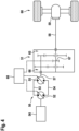
- the drive according to Figure 4 is intended for a mobile work machine, for example a wheel loader, and includes a transmission 49, which represents the combination of a hydrostatic transmission 50 and a mechanical transmission 51 with two gear stages.
- the hydrostatic transmission 50 has a first hydraulic machine 52 designed as an axial piston pump in a swash plate design, which is fluidly connected in a closed hydraulic circuit to a second hydraulic machine 55 designed as an axial piston motor in an inclined axis design via the working line 53 forming one circuit branch and a working line 54 forming the other circuit branch.
- a drive shaft of the first hydraulic machine is coupled to a drive shaft of a drive machine 56 designed as a diesel engine.
- a drive shaft of the second hydraulic machine 55 is coupled to an input shaft 57 of the manual transmission 51.
- An output shaft 58 of the manual transmission 51 is coupled to a differential 59 of a two-wheel axle 60.
- the swash plate of the hydraulic machine 52 and the cylinder drum of the hydraulic machine 55 can be continuously set to different pivot angles, so that the displacement of each of the two hydraulic machines can be adjusted.
- the pivot angle of the first hydraulic machine can be adjusted beyond a zero position of the swashplate, so that a reversal of the direction of rotation of the second hydraulic machine 55, which can only be pivoted on one side, is possible while maintaining the direction of rotation of the first hydraulic machine 52.
- the manual transmission 51 has a first gear stage 65 with a first gear ratio and a second gear stage 66 with a second gear ratio, different from the first gear ratio, between the speed of the input shaft 57 and the speed of the output shaft 58. Furthermore, the manual transmission 51 has a synchronizing device 67, which can be actuated hydraulically in a manner not shown.
- the hydrostatic transmission 50 has a variable, continuously adjustable gear range.
- the hydrostatic transmission 50 is followed by the manual transmission 51 with the two gear stages 65 and 66.
- the manual transmission 51 is designed by the synchronizing device 67 in such a way that it can be switched while driving.
- a transmission arrangement with this feature is known, for example, under the name "Shift on Fly" by the applicant.
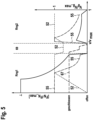
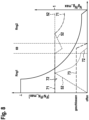
- Driving in one gear stage and switching between gear stages is carried out according to the Figures 1 to 3 trained electronic control unit 68 based on the vehicle parameters and certain variable input variables.
- Curve I indicates the tractive force, curve II the displacement of the hydraulic pump 52, curve III the displacement of the hydraulic motor 55 and curve IV the position of the synchronizing device 67.
- Curve II shows that the hydraulic motor 55 is on during the switching process is pivoted back to a very small pivot angle so that the input shaft 57 of the transmission 51 is torque-free during the switching process.
- the drive system follows Figure 6 in turn has a hydrostatic transmission 50 with a first hydraulic machine 52 which is adjustable in its displacement beyond a zero position and is operated predominantly as a hydraulic pump and which is driven by the internal combustion engine 56, for example by a diesel engine.
- the hydraulic pump 52 is fluidly connected here in a closed hydraulic circuit with two hydraulic motors 71 and 72 arranged parallel to one another, the displacement of which can be adjusted on one side between a minimum value and a maximum value.
- the second hydraulic motor 72 can be temporarily connected via a clutch 73 and via a summation gear 74 to its output shaft 58 and via this to a differential 59 of a two-wheeled axle 60 of a mobile work machine, for example a wheel loader.
- the first hydraulic motor 71 is permanently coupled to its output shaft 58 via the summation gear 74.
- the summation transmission 74 is not a manual transmission with different gear stages.
- Different travel ranges of the travel drive Figure 6 are characterized in that in a first driving range Rng1 the clutch 73 is closed and both the permanent, first hydraulic motor 71 and the temporary hydraulic motor 72 are used to drive the output shaft 58 of the summation gear 74 and that in a second driving range Rng2 the clutch 73 open and the hydraulic motor 72 is pivoted back to zero displacement.
- the second hydraulic motor 72 no longer takes pressure medium conveyed by the hydraulic pump 52. Rather, the entire delivery quantity is swallowed by the first hydraulic motor 71, so that it can rotate significantly faster than in the first travel range Rng1.
- the two circuit diagrams according to the Figures 7 and 8th differ from each other in that according to the circuit diagram Figure 7 the hydraulic motor 71, which is permanently connected to the output shaft 58, and the hydraulic motor 72 are pivoted back to the same minimum pivot angle in the first travel range Rng1, before the hydraulic motor 72 is pivoted back to zero pivot angle in the transition region and the hydraulic motor 71 is fully pivoted out again , while according to the circuit diagram after Figure 8 In the first travel range Rng1, only the second hydraulic motor 72 is pivoted back, while the first hydraulic motor 71 is fully swung out over the entire first travel range Rng1, in the transition range and over a part of the second travel range Rng2.
- the circuit diagram Figure 8 So it's with the transmission Figure 6 In the first driving range Rng1 only a lower maximum speed than with control according to the circuit diagram Figure 7 .
- the hydraulic motor 71 then pivots back from a point at which the hydraulic pump 55, which has pivoted back slightly in the transition region, is fully pivoted out again.
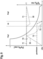
- the circuit diagram according to Figure 9 refers to a transmission similar to the one below Figure 6 .
- the difference is that the second hydraulic motor 72, which is permanently connected to the output shaft 58 of the summation gear 74, is now a constant motor whose displacement cannot be changed.
- a change in the vehicle speed in the second driving range Rng2 is therefore shown in the circuit diagram Figure 9 shows, only achieved by changing the displacement of the hydraulic pump 52.
- Control variables are shown in Table 1 below.
- the control parameters are shown in Table 2.
- Table 1 Control variable Figures 4 and 5 Figures 6 and 7 Figures 6 and 8th Figure 9 version 1
- Variant 2 Variant 3
- Variant 4 ⁇ p,curr the desired pivot angle of the pump used to calculate the control current ⁇ m,1,curr not relevant the desired motor swivel angle used to calculate the control current for the temporary hydraulic motor ⁇ m,2,curr the desired motor swivel angle used to calculate the control current for the hydraulic motor the desired motor swivel angle used to calculate the control current for the permanent hydraulic motor ⁇ m the desired motor swivel angle the desired motor swivel angle ⁇ m the estimated motor swing angle the estimated motor swing angle State Upshifting, downshifting, normal driving the relationship between the temporary engine and the permanent engine Figures 4 and 5 Figures 6 and 7 Figures 6 and 8th Figure 9 version 1 variant Variant 3 Variant 4 ⁇ p ,curr the desired pivot angle of the pump used to calculate the
- Equations (1) and (2) and the variables, parameters and factors shown in Tables 1, 2 and 3 are deposited in the general part 30 of the control architecture.
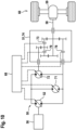
- the electronic controls according to the invention can also be used in combination with transmissions that have more than two driving ranges.
- the hydrostatic transmission part 50 can be used like the drive transmission Figure 6 a first hydraulic machine 52, whose displacement volume can be adjusted beyond a zero position and operated predominantly as a hydraulic pump, which is driven by the internal combustion engine 56, for example by a diesel engine, and has two hydraulic motors 71 and 72, the displacement volume of which is unilaterally between a minimum value and one maximum value can be adjusted, which are arranged parallel to one another and are fluidly connected to the hydraulic pump 52 in a closed hydraulic circuit.
- the travel drive has a first hydraulic motor 71, which has a corresponding to the travel drive Figure 6 additional clutch 78 connected to the output shaft 58 of a mechanical transmission 74 or can be decoupled from it.
- the second hydraulic motor 72 is assigned a further clutch 79, via which it is connected to the second gear stage, which has a different gear ratio than the first spur gear stage Output shaft 58 can be connected.
- the two clutches 73 and 79 are either both open or either the clutch 73 or the clutch 79 is closed.
- the control device 68 is also electrically connected to the two additional clutches 78 and 79 in order to control them.
- both hydraulic motors 71 and 72 work and deliver their power to the output shaft 58.
- both hydraulic motors 71 and 72 are reduced in their respective displacement in the first driving range Rng1.
- the clutch 73 is open, so that only the first hydraulic motor 71 delivers power to the output shaft 58 via the clutch 78, which is still closed.
- the displacement volume of the hydraulic motor 71 which was adjusted to its maximum value during the change of driving range, is constantly reduced.
- the clutch 78 is opened so that the first hydraulic motor 71 is decoupled and the clutch 79 is closed.
- the second hydraulic motor 72 is connected to the output shaft 58 via the third clutch 79 and the second gear stage, so that only the second hydraulic motor 72 supplies power to the output shaft 58 via a different gear ratio than the first hydraulic motor 71 in the second driving range Rng2 gives away.
- the displacement volume of the hydraulic motor 72 which was adjusted to its maximum value during the change from the second driving range Rng2 to the third driving range Rng3, is constantly reduced for an increasing driving speed of a mobile work machine.
- the mechanical transmission 74 according to Figure 10 is therefore, on the one hand, a summation transmission, but on the other hand also a manual transmission, which translates the speed of the output shaft of the hydraulic motor 72 differently depending on the state of the clutches 73 and 79. After its displacement has increased from zero to the maximum value, the hydraulic pump 52 remains fully swiveled out to the maximum speed.
- the drive according to Figure 12 has a drive transmission that is the combination of a hydrostatic transmission 50, as already mentioned Figure 4 can be seen and that has a hydraulic pump 52 and a hydraulic motor 55 arranged with it in a closed hydraulic circuit, and a mechanical gearbox 51 with two gear stages.
- the drive shaft of the hydraulic pump 52 is coupled to a diesel engine 56.
- the drive shaft of the hydraulic motor 55 is coupled to the input shaft 57 of the manual transmission 51.
- An output shaft 58 of the manual transmission 51 is coupled to a differential 59 of a two-wheel axle 60.
- the swash plate of the hydraulic pump 52 and the cylinder drum of the hydraulic motor 55 can be continuously set to different pivot angles, so that the displacement of each of the two hydraulic machines can be adjusted.
- the pivoting angle of the hydraulic pump can be adjusted beyond a zero position of the swashplate, so that a reversal of the direction of rotation of the hydraulic motor 55, which can only be pivoted on one side, is possible while maintaining the direction of rotation of the hydraulic pump 52.
- the manual transmission 51 is designed as a dual clutch transmission and is shown in a very simplified manner.
- the hydraulic motor 55 can alternatively be connected to the output shaft 58 of the transmission 51 via a first clutch 80 and a first transmission branch 81 and via a second clutch 82 and a second transmission branch 83, the translation in the second transmission branch 83 being greater than in the first transmission branch 81.
- such a transmission can contain a planetary stage with a sun gear, with planetary gears and with a ring gear, the ring gear being firmly connected to a frame via a first clutch so that it cannot rotate, and in a rotationally fixed manner via a second clutch the sun gear or its drive shaft can be connected.
- clutch 80 In a first low speed driving range, clutch 80 is closed while clutch 82 is closed. In a second driving range with higher speeds than in the first driving range, the clutch 82 is closed, while the clutch 80 is closed.
Claims (8)
- Système d'entraînement pour un véhicule doté d'une transmission d'entraînement (49), qui permet une conduite selon plusieurs plages de conduite (Rngl, Rng2) et dans laquelle une transmission mécanique (51, 74) est combinée avec une transmission hydrostatique (50), qui comprend une pompe hydraulique (52) réglable quant à son volume de travail et au moins un moteur hydraulique (55), qui est agencé avec la pompe hydraulique (52) dans un circuit hydraulique fermé avec deux branches de circuit (53, 54) et qui est relié à une entrée (57) de la transmission mécanique (51, 74), et comprenant un appareil de commande électronique (68) pour l'exécution d'une commande basée sur la force de traction, caractérisé en ce qu'une différence de pression de consigne (Δpdes) entre les deux branches de circuit (53, 54) du circuit hydraulique fermé est déterminée par l'appareil de commande électronique (68), à partir de paramètres du véhicule présents avant un changement de la plage de conduite, la force de traction cible (Tdes) souhaitée après le changement de la plage de conduite et à partir de la force de traction cible (Tdes) souhaitée et d'un volume de travail (αm) du au moins un moteur hydraulique (55), et en ce qu'après le changement de la plage de conduite entre les deux branches (53, 54) du circuit hydraulique fermé, une différence de pression correspondant à la différence de pression de consigne est réglée par un régulateur de pression (41).
- Système d'entraînement selon la revendication 1, dans lequel la force de traction cible souhaitée (Tdes) est égale à la force de traction avant le changement de plage de conduite (Rngl, Rng2).
- Système d'entraînement selon la revendication 1 ou 2, dans lequel la position (αped) d'une pédale d'accélérateur est prise en compte dans la détermination de la force de traction cible souhaitée (Tdes).
- Système d'entraînement selon la revendication 3, dans lequel la vitesse (vveh) du véhicule intervient dans la détermination de la force de traction cible souhaitée (Tdes).
- Système d'entraînement selon une revendication précédente, dans lequel au moins un moteur hydraulique (55, 71, 72) est réglable dans son volume de travail et dans lequel le volume de travail normalisé (αm) de l'au moins un moteur hydraulique (55, 71, 72), entrant dans la détermination de la différence de pression de consigne (Δpdes), est déterminé selon la formule αm = min (npVp/nmVm, 1), dans laquelle np est la vitesse de rotation de la pompe hydraulique (52), nm est la vitesse de rotation du moteur hydraulique (55, 71, 72), Vp est le volume de travail maximal de la pompe hydraulique (52) et Vm est le volume de travail maximal du moteur hydraulique (55) ou des moteurs hydrauliques (71, 72).
- Système d'entraînement selon la revendication 5, dans lequel la vitesse de rotation du moteur hydraulique est détectée par un capteur de vitesse de rotation.
- Système d'entraînement selon la revendication 5, dans lequel la vitesse de rotation du moteur hydraulique est déterminée à partir de la vitesse du véhicule.
- Système d'entraînement selon une revendication précédente, dans lequel la transmission mécanique (51) présente au moins deux rapports de vitesse et passe d'un rapport de vitesse à un autre lors du changement de la plage de conduite (Rngl, Rng2).
Applications Claiming Priority (1)
| Application Number | Priority Date | Filing Date | Title |
|---|---|---|---|
| DE102019218901.6A DE102019218901A1 (de) | 2019-12-04 | 2019-12-04 | Fahrantrieb für ein Fahrzeug mit einem Fahrgetriebe und Steuerarchitektur zum Steuern des Fahrgetriebes |
Publications (3)
| Publication Number | Publication Date |
|---|---|
| EP3832165A2 EP3832165A2 (fr) | 2021-06-09 |
| EP3832165A3 EP3832165A3 (fr) | 2021-09-01 |
| EP3832165B1 true EP3832165B1 (fr) | 2024-01-31 |
Family
ID=73597856
Family Applications (1)
| Application Number | Title | Priority Date | Filing Date |
|---|---|---|---|
| EP20209663.2A Active EP3832165B1 (fr) | 2019-12-04 | 2020-11-25 | Système d'entraînement pour un véhicule doté d'un engrenage d'entraînement et architecture de commande permettant de commander l'engrenage d'entraînement |
Country Status (2)
| Country | Link |
|---|---|
| EP (1) | EP3832165B1 (fr) |
| DE (1) | DE102019218901A1 (fr) |
Families Citing this family (1)
| Publication number | Priority date | Publication date | Assignee | Title |
|---|---|---|---|---|
| DE102020210196A1 (de) | 2020-08-12 | 2022-02-17 | Robert Bosch Gesellschaft mit beschränkter Haftung | Verfahren zur realisierung einer in der leistung limitierbaren drehmomente- und drehzahlschnittstelle für hydrostatische fahrantriebe |
Family Cites Families (5)
| Publication number | Priority date | Publication date | Assignee | Title |
|---|---|---|---|---|
| DE4223846C2 (de) * | 1992-07-20 | 1996-03-28 | Hydromatik Gmbh | Getriebeeinheit zur Anordnung zwischen einem Antriebsmotor und einem Verbraucher |
| DE19524189C2 (de) * | 1995-07-03 | 1997-07-17 | Brueninghaus Hydromatik Gmbh | Hydrostatischer Antrieb mit nachgeschaltetem Lastschaltgetriebe |
| DE102011055174A1 (de) * | 2011-11-09 | 2013-05-16 | Linde Material Handling Gmbh | Verfahren zum Schalten eines zwischen mindestens zwei Übersetzungsstufen schaltbaren Schaltgetriebes eines Fahrantriebs |
| EP3553347B1 (fr) * | 2017-06-27 | 2021-07-07 | Komatsu Ltd. | Véhicule de travail et procédé de commande d'un véhicule de travail |
| DE102017220003B3 (de) * | 2017-11-10 | 2018-12-20 | Zf Friedrichshafen Ag | Verfahren zur Leistungs- und/oder Drehmomentbestimmung im Fahrantrieb eines CVT Getriebes einer Arbeitsmaschine |
-
2019
- 2019-12-04 DE DE102019218901.6A patent/DE102019218901A1/de active Pending
-
2020
- 2020-11-25 EP EP20209663.2A patent/EP3832165B1/fr active Active
Also Published As
| Publication number | Publication date |
|---|---|
| DE102019218901A1 (de) | 2021-06-10 |
| EP3832165A2 (fr) | 2021-06-09 |
| EP3832165A3 (fr) | 2021-09-01 |
Similar Documents
| Publication | Publication Date | Title |
|---|---|---|
| EP0339202B1 (fr) | Dispositif de transmission pour machines et véhicules | |
| DE112005001920B4 (de) | Laststeuervorrichtung für den Motor eines Arbeitsfahrzeugs | |
| DE60024935T2 (de) | Schaltsteuerung für Getriebe | |
| DE112008000724T5 (de) | Steuerung eines Fahrzeugs mit hydrostatischem, stufenlos variablem Getriebe | |
| DE112008002936T5 (de) | Antriebssystem mit einem kontinuierlichen variablen Getriebe | |
| DE112013001188T5 (de) | Hydromechanisches Mehrbereichsgetriebe | |
| WO2008068036A1 (fr) | Procédé de commande d'un entraînement, et système d'entraînement | |
| DE202007014676U1 (de) | Hydraulisches Antriebssystem | |
| DE112012004575T5 (de) | Hystat-Antriebssystem mit Ausrollfunktionalität | |
| EP1828643B1 (fr) | Procede pour freiner un vehicule entraine au moyen d'une boite de vitesses hydrostatique et boite de vitesses hydrostatique | |
| WO2011131286A1 (fr) | Procédé de limitation de la pression dans une boîte de vitesses hydrostatique | |
| EP2789882B1 (fr) | Engrenage à puissance dérivée pour un entraînement de roulement et procédé de commande de l'engrenage | |
| DE112012004582B4 (de) | Hystat-Antriebssystem mit Brennkraftmaschinendrehzahlsteuerung | |
| DE102004046177A1 (de) | Fahrzeugsteuerungssystem | |
| EP3832165B1 (fr) | Système d'entraînement pour un véhicule doté d'un engrenage d'entraînement et architecture de commande permettant de commander l'engrenage d'entraînement | |
| DE102008025683B4 (de) | Verfahren zur Ansteuerung eines Fahrantriebs | |
| DE102016200336A1 (de) | Verfahren zum Betreiben eines Fahrzeugantriebsstranges einer Arbeitsmaschine mit einer Antriebsmaschine, mit einem Getriebe und mit einem Abtrieb | |
| DE102012218974A1 (de) | Verfahren zum Schalten zwischen Übersetzungsbereichen eines Leistungsverzweigungsgetriebes mit Variator | |
| DE102011121880A1 (de) | Verfahren zum Betätigen einer hydraulisch betätigten Kupplung eines Leistungsverzweigungsgetriebes mit Variator | |
| DE102013202385A1 (de) | Verfahren zur Steuerung eines hydrostatischen Getriebes | |
| DE102012218973A1 (de) | Verfahren zum Bestimmen einer Betätigungszeit einer Kupplungsanordnung eines Leistungsverzweigungsgetriebes mit Variator | |
| DE10133358A1 (de) | Hydrostatischer Antrieb und Verfahren zum Wechseln von Gängen eines einem hydrostatischen Getriebe nachgeschalteten Schaltgetriebes | |
| DE102016205891A1 (de) | Hydrostatischer Fahrantrieb und Fahrzeug mit einem solchen hydrostatischen Fahrantrieb | |
| DE202020107297U1 (de) | Steuersystem für einen hydrostatischen Antrieb | |
| DE102017203544A1 (de) | Verfahren zum Betreiben eines hydrostatischen Getriebes eines Antriebsstranges eines Kraftfahrzeuges |
Legal Events
| Date | Code | Title | Description |
|---|---|---|---|
| PUAI | Public reference made under article 153(3) epc to a published international application that has entered the european phase |
Free format text: ORIGINAL CODE: 0009012 |
|
| STAA | Information on the status of an ep patent application or granted ep patent |
Free format text: STATUS: THE APPLICATION HAS BEEN PUBLISHED |
|
| AK | Designated contracting states |
Kind code of ref document: A2 Designated state(s): AL AT BE BG CH CY CZ DE DK EE ES FI FR GB GR HR HU IE IS IT LI LT LU LV MC MK MT NL NO PL PT RO RS SE SI SK SM TR |
|
| PUAL | Search report despatched |
Free format text: ORIGINAL CODE: 0009013 |
|
| AK | Designated contracting states |
Kind code of ref document: A3 Designated state(s): AL AT BE BG CH CY CZ DE DK EE ES FI FR GB GR HR HU IE IS IT LI LT LU LV MC MK MT NL NO PL PT RO RS SE SI SK SM TR |
|
| RIC1 | Information provided on ipc code assigned before grant |
Ipc: F16H 47/02 20060101AFI20210729BHEP Ipc: F16H 61/42 20100101ALI20210729BHEP Ipc: F16H 61/444 20100101ALI20210729BHEP Ipc: F16H 61/472 20100101ALI20210729BHEP Ipc: F16H 61/04 20060101ALI20210729BHEP Ipc: F16H 61/70 20060101ALI20210729BHEP |
|
| STAA | Information on the status of an ep patent application or granted ep patent |
Free format text: STATUS: REQUEST FOR EXAMINATION WAS MADE |
|
| 17P | Request for examination filed |
Effective date: 20220301 |
|
| RBV | Designated contracting states (corrected) |
Designated state(s): AL AT BE BG CH CY CZ DE DK EE ES FI FR GB GR HR HU IE IS IT LI LT LU LV MC MK MT NL NO PL PT RO RS SE SI SK SM TR |
|
| GRAP | Despatch of communication of intention to grant a patent |
Free format text: ORIGINAL CODE: EPIDOSNIGR1 |
|
| STAA | Information on the status of an ep patent application or granted ep patent |
Free format text: STATUS: GRANT OF PATENT IS INTENDED |
|
| INTG | Intention to grant announced |
Effective date: 20231023 |
|
| GRAS | Grant fee paid |
Free format text: ORIGINAL CODE: EPIDOSNIGR3 |
|
| GRAA | (expected) grant |
Free format text: ORIGINAL CODE: 0009210 |
|
| STAA | Information on the status of an ep patent application or granted ep patent |
Free format text: STATUS: THE PATENT HAS BEEN GRANTED |
|
| AK | Designated contracting states |
Kind code of ref document: B1 Designated state(s): AL AT BE BG CH CY CZ DE DK EE ES FI FR GB GR HR HU IE IS IT LI LT LU LV MC MK MT NL NO PL PT RO RS SE SI SK SM TR |
|
| REG | Reference to a national code |
Ref country code: GB Ref legal event code: FG4D Free format text: NOT ENGLISH Ref country code: CH Ref legal event code: EP |
|
| REG | Reference to a national code |
Ref country code: DE Ref legal event code: R096 Ref document number: 502020006868 Country of ref document: DE |
|
| REG | Reference to a national code |
Ref country code: IE Ref legal event code: FG4D Free format text: LANGUAGE OF EP DOCUMENT: GERMAN |