EP3553347B1 - Véhicule de travail et procédé de commande d'un véhicule de travail - Google Patents
Véhicule de travail et procédé de commande d'un véhicule de travail Download PDFInfo
- Publication number
- EP3553347B1 EP3553347B1 EP18823198.9A EP18823198A EP3553347B1 EP 3553347 B1 EP3553347 B1 EP 3553347B1 EP 18823198 A EP18823198 A EP 18823198A EP 3553347 B1 EP3553347 B1 EP 3553347B1
- Authority
- EP
- European Patent Office
- Prior art keywords
- target
- controller
- flow rate
- traveling
- pump
- Prior art date
- Legal status (The legal status is an assumption and is not a legal conclusion. Google has not performed a legal analysis and makes no representation as to the accuracy of the status listed.)
- Active
Links
- 238000000034 method Methods 0.000 title claims description 24
- 238000006073 displacement reaction Methods 0.000 claims description 69
- 239000012530 fluid Substances 0.000 claims description 51
- 230000005540 biological transmission Effects 0.000 claims description 31
- 230000002706 hydrostatic effect Effects 0.000 claims description 20
- 230000004044 response Effects 0.000 claims description 4
- 238000010586 diagram Methods 0.000 description 27
- 230000000875 corresponding effect Effects 0.000 description 21
- 230000001133 acceleration Effects 0.000 description 19
- 230000008859 change Effects 0.000 description 11
- 230000008569 process Effects 0.000 description 11
- 239000000446 fuel Substances 0.000 description 10
- 230000003068 static effect Effects 0.000 description 10
- 230000002596 correlated effect Effects 0.000 description 6
- 230000001276 controlling effect Effects 0.000 description 5
- 230000007423 decrease Effects 0.000 description 4
- 101001047777 Bacillus subtilis (strain 168) Ribosome hibernation promotion factor Proteins 0.000 description 3
- 238000007562 laser obscuration time method Methods 0.000 description 3
- 238000004364 calculation method Methods 0.000 description 2
- 230000000052 comparative effect Effects 0.000 description 2
- 230000006870 function Effects 0.000 description 2
- 238000010521 absorption reaction Methods 0.000 description 1
- 230000000903 blocking effect Effects 0.000 description 1
- 230000000694 effects Effects 0.000 description 1
- 238000002474 experimental method Methods 0.000 description 1
- 238000002347 injection Methods 0.000 description 1
- 239000007924 injection Substances 0.000 description 1
- 230000007935 neutral effect Effects 0.000 description 1
- 239000004065 semiconductor Substances 0.000 description 1
- 238000004088 simulation Methods 0.000 description 1
- 239000000243 solution Substances 0.000 description 1
- 230000007704 transition Effects 0.000 description 1
Images


Classifications
-
- F—MECHANICAL ENGINEERING; LIGHTING; HEATING; WEAPONS; BLASTING
- F16—ENGINEERING ELEMENTS AND UNITS; GENERAL MEASURES FOR PRODUCING AND MAINTAINING EFFECTIVE FUNCTIONING OF MACHINES OR INSTALLATIONS; THERMAL INSULATION IN GENERAL
- F16H—GEARING
- F16H61/00—Control functions within control units of change-speed- or reversing-gearings for conveying rotary motion ; Control of exclusively fluid gearing, friction gearing, gearings with endless flexible members or other particular types of gearing
- F16H61/38—Control of exclusively fluid gearing
- F16H61/40—Control of exclusively fluid gearing hydrostatic
- F16H61/42—Control of exclusively fluid gearing hydrostatic involving adjustment of a pump or motor with adjustable output or capacity
- F16H61/431—Pump capacity control by electro-hydraulic control means, e.g. using solenoid valves
-
- F—MECHANICAL ENGINEERING; LIGHTING; HEATING; WEAPONS; BLASTING
- F16—ENGINEERING ELEMENTS AND UNITS; GENERAL MEASURES FOR PRODUCING AND MAINTAINING EFFECTIVE FUNCTIONING OF MACHINES OR INSTALLATIONS; THERMAL INSULATION IN GENERAL
- F16H—GEARING
- F16H61/00—Control functions within control units of change-speed- or reversing-gearings for conveying rotary motion ; Control of exclusively fluid gearing, friction gearing, gearings with endless flexible members or other particular types of gearing
- F16H61/38—Control of exclusively fluid gearing
- F16H61/40—Control of exclusively fluid gearing hydrostatic
- F16H61/42—Control of exclusively fluid gearing hydrostatic involving adjustment of a pump or motor with adjustable output or capacity
- F16H61/421—Motor capacity control by electro-hydraulic control means, e.g. using solenoid valves
-
- F—MECHANICAL ENGINEERING; LIGHTING; HEATING; WEAPONS; BLASTING
- F16—ENGINEERING ELEMENTS AND UNITS; GENERAL MEASURES FOR PRODUCING AND MAINTAINING EFFECTIVE FUNCTIONING OF MACHINES OR INSTALLATIONS; THERMAL INSULATION IN GENERAL
- F16H—GEARING
- F16H61/00—Control functions within control units of change-speed- or reversing-gearings for conveying rotary motion ; Control of exclusively fluid gearing, friction gearing, gearings with endless flexible members or other particular types of gearing
- F16H61/38—Control of exclusively fluid gearing
- F16H61/40—Control of exclusively fluid gearing hydrostatic
- F16H61/46—Automatic regulation in accordance with output requirements
- F16H61/472—Automatic regulation in accordance with output requirements for achieving a target output torque
-
- B—PERFORMING OPERATIONS; TRANSPORTING
- B60—VEHICLES IN GENERAL
- B60Y—INDEXING SCHEME RELATING TO ASPECTS CROSS-CUTTING VEHICLE TECHNOLOGY
- B60Y2200/00—Type of vehicle
- B60Y2200/40—Special vehicles
- B60Y2200/41—Construction vehicles, e.g. graders, excavators
-
- B—PERFORMING OPERATIONS; TRANSPORTING
- B60—VEHICLES IN GENERAL
- B60Y—INDEXING SCHEME RELATING TO ASPECTS CROSS-CUTTING VEHICLE TECHNOLOGY
- B60Y2200/00—Type of vehicle
- B60Y2200/40—Special vehicles
- B60Y2200/41—Construction vehicles, e.g. graders, excavators
- B60Y2200/415—Wheel loaders
-
- E—FIXED CONSTRUCTIONS
- E02—HYDRAULIC ENGINEERING; FOUNDATIONS; SOIL SHIFTING
- E02F—DREDGING; SOIL-SHIFTING
- E02F9/00—Component parts of dredgers or soil-shifting machines, not restricted to one of the kinds covered by groups E02F3/00 - E02F7/00
- E02F9/20—Drives; Control devices
- E02F9/22—Hydraulic or pneumatic drives
- E02F9/2253—Controlling the travelling speed of vehicles, e.g. adjusting travelling speed according to implement loads, control of hydrostatic transmission
-
- F—MECHANICAL ENGINEERING; LIGHTING; HEATING; WEAPONS; BLASTING
- F16—ENGINEERING ELEMENTS AND UNITS; GENERAL MEASURES FOR PRODUCING AND MAINTAINING EFFECTIVE FUNCTIONING OF MACHINES OR INSTALLATIONS; THERMAL INSULATION IN GENERAL
- F16H—GEARING
- F16H59/00—Control inputs to control units of change-speed-, or reversing-gearings for conveying rotary motion
- F16H59/68—Inputs being a function of gearing status
- F16H2059/6838—Sensing gearing status of hydrostatic transmissions
- F16H2059/6861—Sensing gearing status of hydrostatic transmissions the pressures, e.g. high, low or differential pressures
-
- F—MECHANICAL ENGINEERING; LIGHTING; HEATING; WEAPONS; BLASTING
- F16—ENGINEERING ELEMENTS AND UNITS; GENERAL MEASURES FOR PRODUCING AND MAINTAINING EFFECTIVE FUNCTIONING OF MACHINES OR INSTALLATIONS; THERMAL INSULATION IN GENERAL
- F16H—GEARING
- F16H59/00—Control inputs to control units of change-speed-, or reversing-gearings for conveying rotary motion
- F16H59/14—Inputs being a function of torque or torque demand
- F16H59/18—Inputs being a function of torque or torque demand dependent on the position of the accelerator pedal
-
- F—MECHANICAL ENGINEERING; LIGHTING; HEATING; WEAPONS; BLASTING
- F16—ENGINEERING ELEMENTS AND UNITS; GENERAL MEASURES FOR PRODUCING AND MAINTAINING EFFECTIVE FUNCTIONING OF MACHINES OR INSTALLATIONS; THERMAL INSULATION IN GENERAL
- F16H—GEARING
- F16H59/00—Control inputs to control units of change-speed-, or reversing-gearings for conveying rotary motion
- F16H59/36—Inputs being a function of speed
- F16H59/44—Inputs being a function of speed dependent on machine speed of the machine, e.g. the vehicle
-
- F—MECHANICAL ENGINEERING; LIGHTING; HEATING; WEAPONS; BLASTING
- F16—ENGINEERING ELEMENTS AND UNITS; GENERAL MEASURES FOR PRODUCING AND MAINTAINING EFFECTIVE FUNCTIONING OF MACHINES OR INSTALLATIONS; THERMAL INSULATION IN GENERAL
- F16H—GEARING
- F16H63/00—Control outputs from the control unit to change-speed- or reversing-gearings for conveying rotary motion or to other devices than the final output mechanism
- F16H63/40—Control outputs from the control unit to change-speed- or reversing-gearings for conveying rotary motion or to other devices than the final output mechanism comprising signals other than signals for actuating the final output mechanisms
- F16H63/50—Signals to an engine or motor
Definitions
- the present invention relates to a work vehicle and a control method for a work vehicle.
- the hydrostatic transmission includes a traveling pump, a traveling motor, and a hydraulic circuit connecting the traveling pump and the traveling motor.
- the traveling pump is driven by the engine and discharges hydraulic fluid.
- the hydraulic fluid discharged from the traveling pump is supplied to the traveling motor via the hydraulic circuit.
- the traveling motor is driven by hydraulic fluid from the traveling pump.
- the traveling motor is connected to a traveling device of the work vehicle, and the work vehicle travels by driving the traveling motor.
- the transmission gear ratio can be controlled by controlling the displacement of the traveling pump and the displacement of the traveling motor.
- the displacement of the traveling pump is controlled by a pump displacement control device.
- the pump displacement control device includes a pump control cylinder.
- the pump control cylinder is connected to the swash plate of the traveling pump and changes the displacement of the traveling pump by changing the tilting angle of the swash plate.
- the pump control cylinder is controlled by the hydraulic pressure of a pump pilot circuit connected to the pump control cylinder.
- FIG. 17 is a diagram showing PQ characteristics of a traveling pump according to the conventional art.
- the horizontal axis represents the displacement of the traveling pump
- the vertical axis represents the differential pressure (HST differential pressure) of the hydraulic circuit of the hydrostatic transmission.
- the PQ characteristics are changed according to engine speed.
- the hydraulic pressure of the above-described pump pilot circuit is changed in accordance with the engine speed, whereby the PQ characteristics are changed as shown by PQ1 to PQ5 in FIG. 17 .
- PQs in FIG. 17 indicates the PQ characteristic in stalling of the work vehicle.
- the PQ characteristic at stall indicates the characteristic (block characteristic) when the traveling motor is in a stall equivalent state by blocking the discharge port of the traveling pump. As shown in FIG. 17 , at the time of stalling, the HST differential pressure increases in accordance with the increase of the displacement of the traveling pump.
- the HST differential pressure in stalling changes as P1 to P3 according to the engine speed.
- PQmax indicates the maximum value of the HST differential pressure. Therefore, the HST differential pressure in stalling is maximum at P3.
- JP 2008-275012 A US 2010/094515 A1 , WO 2014/006302 A1 , US 2011/295473 A1 , US 5 070 695 A , US 7 536 856 B2 .
- the engine speed is set according to the operation amount of the accelerator. Therefore, assuming that the operation amount of the accelerator corresponding to the PQ characteristic PQ3 of FIG. 17 is 50%, the HST differential pressure in stalling becomes the maximum value P3 at the operation amount of 50%.
- the HST differential pressure corresponds to the traction force of the vehicle. Therefore, at 50% of the operation amount, the traction force in stalling becomes maximum.
- FIG. 18A shows a change in traction force with respect to the operation amount of the accelerator in the conventional work vehicle described above.
- FIG. 18B shows a change in engine speed with respect to the operation amount of the accelerator in the above-described conventional work vehicle.
- the traction force increases from 0 to 50% of the operation amount, but the traction force becomes constant at the maximum value Fmax at 50% or more.
- the engine speed increases even if the operation amount is 50% or more.
- the increase in the traction force is large when the operation amount is in the small to medium range, but the increase in the traction force is hardly in the medium to large range. Therefore, there is a problem that the operability is low.
- the operation amount is in the range of medium to large, while the increase in traction force is small, the engine speed is unnecessarily increased, so that there is a problem that the fuel efficiency decreases.
- the work vehicle mentioned above is provided with a traction control function for reducing the maximum traction force.
- the maximum traction force is reduced by limiting the displacement of the traveling motor to a predetermined upper limit value or less smaller than the maximum displacement.
- An object of the present invention is to control a traction force in stalling arbitrarily, accurately and efficiently in a work vehicle provided with a hydrostatic transmission.
- a work vehicle includes an engine, a hydrostatic transmission, a storage device, and a controller.
- the hydrostatic transmission includes a traveling pump, a hydraulic circuit, and a traveling motor.
- the traveling pump is driven by the engine.
- the hydraulic circuit includes a first drive circuit and a second drive circuit and is connected to the traveling pump.
- the traveling motor is connected to the traveling pump via the hydraulic circuit.
- a closed circuit is formed by the traveling pump, the first drive circuit, the second drive circuit, and the traveling motor.
- the storage device stores leakage flow rate data.
- the leakage flow rate data defines a relationship between a differential pressure of the hydraulic fluid between the first drive circuit and the second drive circuit and the leakage flow rate of the hydraulic fluid in the hydraulic circuit in stalling.
- the controller communicates with the storage device.
- the controller determines a target traction force of the vehicle.
- the controller determines a target differential pressure which is a target value of the differential pressure from the target traction force.
- the controller determines the leakage flow rate from the target differential pressure by referring to the leakage flow rate data.
- the controller determines the target flow rate of the traveling pump from the leakage flow rate.
- the leakage flow rate is determined from the target differential pressure by referring to the leakage flow rate data, and the target flow rate of the traveling pump is determined from the leakage flow rate.
- the leakage flow rate from the hydraulic circuit of the hydrostatic transmission is correlated with the differential pressure of the hydraulic circuit.
- the leakage flow rate is correlated with the flow rate of the traveling pump. Therefore, by referring to the leakage flow rate data, it is possible to accurately determine the target differential pressure, that is, the target flow rate of the traveling pump corresponding to the target traction force. Thereby, the traction force in stalling can be controlled arbitrarily, accurately and efficiently.
- the work vehicle may further include an accelerator and a sensor.
- the accelerator may be operably disposed by the operator.
- the sensor may output a signal indicating an operation amount of the accelerator.
- the controller may receive the signal from the sensor.
- the controller may determine the target traction force from the operation amount of the accelerator. In this case, it is possible to accurately achieve the target traction force according to the operation amount of the accelerator. Therefore, the operator can easily adjust the traction force of the vehicle by operating the accelerator.
- the storage device may store target traction data.
- the target traction data may define a relationship between the operation amount of the accelerator and the target traction force.
- the controller may determine the target traction force from the operation amount of the accelerator with reference to the target traction data. In this case, it is possible to accurately achieve the target traction force according to the operation amount of the accelerator. Therefore, the operator can easily adjust the traction force of the vehicle by operating the accelerator.
- the controller may determine the target torque of the traveling motor from the target traction force.
- the controller may determine the target differential pressure from the target torque and the displacement of the traveling motor. In this case, it is possible to accurately determine the target differential pressure corresponding to the target traction force.
- the work vehicle may further include a temperature sensor.
- the temperature sensor may output a signal indicative of the temperature of the hydraulic fluid in the hydraulic circuit.
- the controller may receive the signal from the temperature sensor.
- the controller may correct the leakage flow rate according to the temperature of the hydraulic fluid. In this case, the target flow rate of the traveling pump can be more accurately determined in consideration of the temperature error of the hydraulic fluid.
- the controller may increase the leakage flow rate in response to the increase in temperature of the hydraulic fluid.
- the target flow rate of the traveling pump can be more accurately determined in consideration of the temperature error of the hydraulic fluid.
- the work vehicle may further include an input device for selecting a traction level.
- the controller may receive from the input device a signal indicative of the selected traction level.
- the controller may correct the target traction force according to the selected traction level.
- the controller may determine the target differential pressure from the corrected target traction force. In this case, the traction force can be controlled arbitrarily and precisely according to the selected traction level.
- the controller may determine the target input horsepower to the hydrostatic transmission from the traveling pump target flow rate.
- the controller may determine the target rotational speed of the engine from the target input horsepower. In this case, it is possible to accurately determine the target rotational speed of the engine for achieving the target traction force.
- a method is a method executed by a controller for controlling a work vehicle.
- the work vehicle includes an engine and a hydrostatic transmission.
- the hydrostatic transmission includes a traveling pump, a hydraulic circuit, and a traveling motor.
- the traveling pump is driven by the engine.
- the hydraulic circuit includes a first drive circuit and a second drive circuit and is connected to the traveling pump.
- the traveling motor is connected to the traveling pump via the hydraulic circuit.
- a closed circuit is formed by the traveling pump, the first drive circuit, the second drive circuit, and the traveling motor.
- the method according to the present aspect includes the following processing.
- the first process is to determine the target traction force of the vehicle.
- the second process is to determine the target differential pressure from the target traction force.
- the target differential pressure is a target value of the differential pressure of the hydraulic fluid between the first drive circuit and the second drive circuit.
- the third process is to determine the leakage flow rate from the target differential pressure by referring to the leakage flow rate data.
- the leakage flow rate data defines the relationship between the differential pressure and the leakage flow rate of the hydraulic fluid in the hydraulic circuit in stalling.
- the fourth process is to determine the target flow rate of the traveling pump from the leakage flow rate.
- the leakage flow rate is determined from the target differential pressure by referring to the leakage flow rate data, and the target flow rate of the traveling pump is determined from the leakage flow rate.
- the leakage flow rate from the hydraulic circuit of the hydrostatic transmission is correlated with the differential pressure of the hydraulic circuit.
- the leakage flow rate is correlated with the flow rate of the traveling pump. Therefore, by referring to the leakage flow rate data, it is possible to accurately determine the target differential pressure, that is, the target flow rate of the traveling pump corresponding to the target traction force. Thereby, the traction force in stalling can be controlled arbitrarily, accurately and efficiently.
- the traction force in stalling can be controlled arbitrarily and accurately and efficiently.
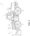
- FIG. 1 is a side view of the work vehicle 1.
- the work vehicle 1 is a wheel loader.
- the work vehicle 1 includes a vehicle body 2, a work implement 3, a plurality of traveling wheels 4, and a cab 5.
- the work implement 3 is attached to the front of the vehicle body 2.
- the work implement 3 includes a boom 11, a bucket 12, a lift cylinder 13 and a bucket cylinder 14.
- the boom 11 is rotatably attached to the vehicle body 2.
- the boom 11 is driven by the lift cylinder 13.
- the bucket 12 is rotatably attached to the boom 11.
- the bucket 12 is moved up and down by the bucket cylinder 14.
- the cab 5 is disposed on the vehicle body 2.
- the plurality of traveling wheels 4 are rotatably attached to the vehicle body 2.
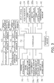
- FIG. 2 is a block diagram showing a configuration of a drive system mounted on work vehicle 1.
- the work vehicle 1 includes an engine 21, a work implement pump 22, and a hydrostatic transmission (hereinafter referred to as "HST") 23.
- the engine 21 is, for example, a diesel engine.
- a fuel injector 24 is connected to the engine 21.
- the fuel injector 24 controls the amount of fuel injection to the engine 21 to control the output torque of the engine 21 (hereinafter referred to as "engine torque") and the rotational speed.
- engine torque the output torque of the engine 21
- the actual rotational speed of the engine 21 is detected by an engine speed sensor 25.
- the engine speed sensor 25 outputs a signal indicative of the actual rotational speed of the engine 21.
- the work implement pump 22 is connected to the engine 21.
- the work implement pump 22 is driven by the engine 21 to discharge hydraulic fluid.
- the hydraulic fluid discharged from the work implement pump 22 is supplied to the lift cylinder 13 via the work implement hydraulic circuit 26. Thereby, the work implement 3 is driven.
- the discharge pressure of the work implement pump 22 is detected by a work implement pump pressure sensor 27.
- the work implement pump pressure sensor 27 outputs a signal indicative of the discharge pressure of the work implement pump 22.
- the work implement pump 22 is a variable displacement hydraulic pump.
- a pump displacement control device 28 is connected to the work implement pump 22.
- the pump displacement control device 28 controls the displacement of the work implement pump 22.
- the pump displacement control device 28 includes a servo piston 28a and a pump control valve 28b.
- the servo piston 28a is connected to the work implement pump 22.
- the displacement of the work implement pump 22 is changed by the servo piston 28a changing the tilt angle of the work implement pump 22.
- the pump control valve 28b controls the hydraulic pressure supplied to the servo piston 28a to control the operation of the servo piston 28a.
- the work implement pump 22 may be a fixed displacement hydraulic pump.
- a work implement control valve 30 is disposed in the work implement hydraulic circuit 26.
- the work implement control valve 30 controls the flow rate of the hydraulic fluid supplied to the lift cylinder 13 in accordance with the pilot pressure applied to the work implement control valve 30.
- the work implement control valve 30 may control the flow rate of the hydraulic fluid supplied to the bucket cylinder 14.
- the flow rate of the hydraulic fluid means the amount of hydraulic fluid supplied per unit time.
- the work implement control valve 30 is not limited to the hydraulic pilot-operated control valve, and may be an electromagnetic control valve that is electrically controlled.
- the HST 23 includes a traveling pump 31, a driving hydraulic circuit 32, and a traveling motor 33.
- the traveling pump 31 is connected to the engine 21.
- the traveling pump 31 discharges hydraulic fluid by being driven by the engine 21.
- the traveling pump 31 is a variable displacement hydraulic pump.
- the hydraulic fluid discharged from the traveling pump 31 is sent to the traveling motor 33 through the driving hydraulic circuit 32.
- the driving hydraulic circuit 32 connects the traveling pump 31 and the traveling motor 33.
- the driving hydraulic circuit 32 includes a first drive circuit 32a and a second drive circuit 32b.
- the first drive circuit 32a connects one port of the traveling pump 31 and one port of the traveling motor 33.
- the second drive circuit 32b connects the other port of the traveling pump 31 and the other port of the traveling motor 33.
- the traveling pump 31, the traveling motor 33, the first drive circuit 32a, and the second drive circuit 32b constitute a closed circuit.
- the traveling motor 33 is driven in one direction (for example, the forward direction) by being supplied from the traveling pump 31 to the traveling motor 33 via the first drive circuit 32a.
- the hydraulic fluid returns from the traveling motor 33 to the traveling pump 31 via the second drive circuit 32b.
- the hydraulic fluid is supplied from the traveling pump 31 to the traveling motor 33 via the second drive circuit 32b, whereby the traveling motor 33 is driven in the other direction (for example, the reverse direction). In this case, the hydraulic fluid returns from the traveling motor 33 to the traveling pump 31 via the first drive circuit 32a.
- the driving hydraulic circuit 32 is provided with a drive circuit pressure sensor 34.
- the drive circuit pressure sensor 34 detects the pressure of the hydraulic fluid supplied to the traveling motor 33 via the first drive circuit 32a or the second drive circuit 32b.
- the drive circuit pressure sensor 34 includes a first circuit pressure sensor 34a and a second circuit pressure sensor 34b.
- the first circuit pressure sensor 34a detects the hydraulic pressure of the first drive circuit 32a.
- the second circuit pressure sensor 34b detects the hydraulic pressure of the second drive circuit 32b.
- the first circuit pressure sensor 34a outputs a signal indicative of the hydraulic pressure of the first drive circuit 32a.
- the second circuit pressure sensor 34b outputs a signal indicative of the hydraulic pressure of the second drive circuit 32b.
- a temperature sensor 49 is provided with the driving hydraulic circuit 32.
- the temperature sensor 49 detects the temperature of the hydraulic fluid supplied to the traveling motor 33.
- the temperature sensor 49 outputs a signal indicative of the temperature of the hydraulic fluid supplied to the traveling motor 33.
- the traveling motor 33 is a variable displacement hydraulic motor.
- the traveling motor 33 is driven by the hydraulic fluid discharged from the traveling pump 31 to generate a driving force for traveling.
- a motor displacement control device 35 is connected to the traveling motor 33.
- the motor displacement control device 35 controls the displacement of the traveling motor 33.
- the motor displacement control device 35 includes a motor cylinder 35a and a motor control valve 35b.
- the motor cylinder 35a is connected to the traveling motor 33.
- the motor cylinder 35a is driven by hydraulic pressure to change the tilt angle of the traveling motor 33.
- the motor control valve 35b is an electromagnetic control valve controlled based on a command signal input to the motor control valve 35b.
- the motor control valve 35b operates the motor cylinder 35a to change the displacement of the traveling motor 33.
- the traveling motor 33 is connected to the drive shaft 37.
- the drive shaft 37 is connected to the traveling wheels 4 described above via an axle (not shown).
- the rotation of the traveling motor 33 is transmitted to the traveling wheels 4 via the drive shaft 37. Thereby, the work vehicle 1 travels.
- the work vehicle 1 is provided with a vehicle speed sensor 36.
- the vehicle speed sensor 36 detects the vehicle speed.
- the vehicle speed sensor 36 outputs a signal indicative of the vehicle speed.
- the vehicle speed sensor 36 detects the vehicle speed by detecting the rotational speed of the drive shaft 37.
- HST 23 includes a charge pump 38 and a charge circuit 39.
- the charge pump 38 is a fixed displacement hydraulic pump.
- the charge pump 38 is connected to the engine 21.
- the charge pump 38 is driven by the engine 21 to supply hydraulic fluid to the driving hydraulic circuit 32.
- the charge circuit 39 is connected to the charge pump 38.
- the charge circuit 39 is connected to the first drive circuit 32a via a first check valve 41.
- the charge circuit 39 is connected to the second drive circuit 32b via a second check valve 42.
- the charge circuit 39 is connected to the first drive circuit 32a via a first relief valve 43.
- the first relief valve 43 is opened when the hydraulic pressure of the first drive circuit 32a becomes larger than a predetermined relief pressure.
- the charge circuit 39 is connected to the second drive circuit 32b via a second relief valve 44.
- the second relief valve 44 is opened when the hydraulic pressure of the second drive circuit 32b becomes larger than a predetermined relief pressure.
- a charge relief valve 40 is provided in the charge circuit 39.
- the charge relief valve 40 is opened when the hydraulic pressure of the charge circuit 39 becomes larger than a predetermined relief pressure. Thereby, the hydraulic pressure of the charge circuit 39 is limited so as not to exceed the predetermined relief pressure.
- a pump displacement control device 45 is connected to the traveling pump 31.
- the pump displacement control device 45 controls the displacement of the traveling pump 31.
- the displacement of the hydraulic pump means the discharge amount (cc / rev) of hydraulic fluid per one rotation. Further, the pump displacement control device 45 controls the discharge direction of the traveling pump 31.
- the pump displacement control device 45 includes a pump control cylinder 46 and a pump control valve 47.
- the pump control cylinder 46 is connected to the traveling pump 31.
- the pump control cylinder 46 is hydraulically driven to change the tilt angle of the traveling pump 31.
- the pump control cylinder 46 changes the displacement of the traveling pump 31.
- the pump control cylinder 46 is connected to the charge circuit 39 via a pump pilot circuit 48.
- the pump control valve 47 is an electromagnetic control valve controlled based on a command signal input to the pump control valve 47.
- the pump control valve 47 switches the supply direction of the hydraulic fluid to the pump control cylinder 46.
- the pump control valve 47 switches the discharge direction of the traveling pump 31 by switching the supply direction of the hydraulic fluid to the pump control cylinder 46. Thereby, the driving direction of the traveling motor 33 is changed, and the forward and reverse of the work vehicle 1 are switched.
- the pump control valve 47 also controls the pressure of hydraulic fluid supplied to the pump control cylinder 46 via the pump pilot circuit 48. Specifically, the pump control valve 47 adjusts the tilt angle of the traveling pump 31 by changing the pressure of the hydraulic fluid supplied to the pump control cylinder 46. Thereby, the displacement of the traveling pump 31 is controlled.
- the pump pilot circuit 48 is connected to the hydraulic fluid tank via the cut-off valve 52.
- the pilot ports of the cut-off valve 52 are connected to the first drive circuit 32a and the second drive circuit 32b via a shuttle valve 53.
- the shuttle valve 53 introduces the larger one of the hydraulic pressure of the first drive circuit 32a and the hydraulic pressure of the second drive circuit 32b (hereinafter referred to as "drive circuit pressure") into the pilot port of the cut-off valve 52.
- the cut-off valve 52 causes the pump pilot circuit 48 to communicate with the hydraulic fluid tank when the drive circuit pressure becomes equal to or higher than a predetermined cut-off pressure. As a result, the hydraulic pressure of the pump pilot circuit 48 is reduced, whereby the displacement of the traveling pump 31 is reduced. As a result, an increase in drive circuit pressure can be suppressed.
- FIG. 3 is a schematic view showing a control system of the work vehicle 1.
- the work vehicle 1 includes an accelerator 61, an FR operating member 62, and a shift operating member 63.
- the accelerator 61, the FR operating member 62, and the shift operating member 63 are disposed to be operable by the operator.
- the accelerator 61, the FR operating member 62, and the shift operating member 63 are disposed in the cab 5.
- the accelerator 61 is, for example, an accelerator pedal. However, the accelerator 61 may be another member such as a lever or a switch.
- the accelerator 61 is connected to an accelerator operation sensor 64.
- the accelerator operation sensor 64 is, for example, a position sensor that detects the position of the accelerator 61.
- the accelerator operation sensor 64 outputs a signal indicative of an operation amount of the accelerator 61 (hereinafter referred to as "accelerator operation amount").
- the accelerator operation amount is, for example, represented by a ratio when the state in which the accelerator 61 is operated fully open is 100%. As described later, the operator can control the vehicle speed and the traction force by adjusting the accelerator operation amount.
- the FR operating member 62 is, for example, an FR lever. However, the FR operating member 62 may be another member such as a switch. The FR operating member 62 is switched between a forward position, a reverse position and a neutral position. The FR operating member 62 is connected to the FR operation sensor 65.
- the FR operation sensor 65 is, for example, a position sensor that detects the position of the FR operating member 62.
- the FR operation sensor 65 outputs a signal indicative of the position of the FR operating member 62. The operator can switch between forward and reverse of the work vehicle 1 by operating the FR operating member 62.
- the shift operating member 63 is, for example, a dial switch. However, the shift operating member 63 may be another member such as a lever.
- the shift operating member 63 is connected to the shift operation sensor 66.
- the shift operation sensor 66 is, for example, a position sensor that detects the position of the shift operating member 63 (hereinafter referred to as "shift position").
- the shift operation sensor 66 outputs a signal indicative of the shift position.
- the shift position includes, for example, the positions of first to fourth speeds. However, the shift position may include a position faster than the fourth speed. Alternatively, the shift position may be from the first speed to a position slower than the fourth speed.
- FIG. 4 is a diagram showing a vehicle speed-traction force characteristic of the work vehicle 1. As shown in FIG. 4 , the operator can select a shift pattern (L_1st to L_4th) that defines the maximum vehicle speed by operating the shift operating member 63.
- the work vehicle 1 includes a work implement operating member 67.
- the work implement operating member 67 is, for example, a work implement lever. However, the work implement operating member 67 may be another member such as a switch.
- a pilot pressure corresponding to the operation of the work implement operating member 67 is applied to the work implement control valve 30.
- the work implement operating member 67 is connected to a work implement operation sensor 68.
- the work implement operation sensor 68 is, for example, a pressure sensor.
- the work implement operation sensor 68 detects the operation amount of the work implement operating member 67 (hereinafter referred to as "work implement operation amount”) and the operation direction, and outputs signals indicative of the work implement operation amount and the operation direction.
- the work implement operation sensor 68 is a position sensor that electrically detects the position of the work implement operating member 67.
- the operator can operate the work implement 3 by operating the work implement operating member 67. For example, the operator can raise or lower the bucket 12 by operating the work implement operating member 67.
- the work vehicle 1 includes an input device 69.
- the input device 69 is, for example, a touch panel.
- the input device 69 is not limited to the touch panel, and may be another device such as a switch.
- the operator can perform various settings of the work vehicle 1 by operating the input device 69.
- the input device 69 can set traction control. As shown in FIG. 4 ,
- the traction control is a feature that allows the maximum traction force to be selected from a plurality of traction levels.
- the plurality of traction levels include a first level and a second level.
- the maximum traction force is limited to a value less than the normal maximum traction force where traction control is disabled.
- the maximum traction force is limited to a value smaller than the maximum traction force at the first level.
- L_max represents the vehicle speed-traction force characteristic of the work vehicle 1 at the normal time when the traction control is disabled.
- L_TC1 shows the vehicle speed-traction force characteristic in the traction control at the first level.
- L_TC2 shows the vehicle speed-traction force characteristic in the traction control at the second level.
- the work vehicle 1 includes a storage device 71 and a controller 72.
- the storage device 71 includes, for example, a memory and an auxiliary storage device.
- the storage device 71 may be, for example, a RAM or a ROM.
- the storage device 71 may be a semiconductor memory or a hard disk.
- the storage device 71 is an example of a non-transitory computer readable recording medium.
- the storage device 71 stores computer instructions that can be executed by a processor and control the work vehicle 1.
- the controller 72 includes, for example, a processor such as a CPU.
- the controller 72 is communicably connected to the above-described sensor, the input device 69, and the storage device 71.
- the controller 72 is communicably connected to the various sensors described above, the input device 69, and the storage device 71 in a wired or wireless manner.
- the controller 72 acquires various data by receiving signals from the sensor, the input device 69, and the storage device 71.
- the controller 72 is programmed to control the work vehicle 1 based on the acquired data.
- the controller 72 may be configured by a plurality of controllers separate from one another.
- the controller 72 is communicably connected to the control valves 35b and 47 and the fuel injector 24 described above in a wired or wireless manner.
- the controller 72 controls the control valves 35b and 47 and the fuel injector 24 by outputting command signals to the control valves 35b and 47 and the fuel injector 24.
- the controller 72 controls the engine torque and the engine speed by outputting a command signal to the fuel injector 24.
- the controller 72 controls the displacement of the traveling motor 33 by outputting a command signal to the motor control valve 35b.
- the controller 72 controls the displacement of the traveling pump 31 by outputting a command signal to the pump control valve 47.
- the controller 72 controls the transmission ratio of the HST 23 by controlling the displacement of the traveling pump and the displacement of the traveling motor so that the vehicle speed-traction force characteristic as shown in FIGS. 4 and 5 is realized.
- the controller 72 determines a target rotational speed of the engine 21 (hereinafter referred to as "target engine speed") based on the accelerator operation amount and the work implement operation amount.
- target engine speed a target rotational speed of the engine 21
- the operator can increase the engine speed by operating the work implement operating member 67 without operating the accelerator 61. Further, even if the work implement operating member 67 and the accelerator 61 are simultaneously operated, the traveling performance of the vehicle can be adjusted by the accelerator 61 without being affected by the operation of the work implement operating member 67.
- FIG. 5 is a view showing an example of a vehicle speed-traction force characteristic which is changed according to the operation of the accelerator 61 by the operator.
- T100 represents the vehicle speed-traction force characteristic when the accelerator operation amount is 100%.
- T80 indicates the vehicle speed-traction force characteristic when the accelerator operation amount is 80%.
- T60 shows the vehicle speed-traction force characteristic when the accelerator operation amount is 60%.
- traveling performance can be obtained according to the accelerator operation amount.
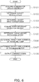
- FIG. 6 is a flowchart showing the process executed by the controller 72.
- control when the work vehicle 1 moves forward will be described. However, similar control may be performed when the work vehicle 1 moves backward.
- the controller 72 acquires an accelerator operation amount.
- the controller 72 acquires the accelerator operation amount in accordance with a signal from the accelerator operation sensor 64.
- step S102 the controller 72 determines a target vehicle speed.
- the controller 72 determines the target vehicle speed from the accelerator operation amount.
- FIG. 7 shows a process for determining the target vehicle speed from the accelerator operation amount.
- the controller 72 determines a target reference vehicle speed from the accelerator operation amount and the shift position.
- the target reference vehicle speed is a vehicle speed that is set as the target achieved vehicle speed when the work vehicle 1 travels on a flat ground.
- the storage device 71 stores reference vehicle speed data D1 that defines the relationship between the accelerator operation amount and the target reference vehicle speed.
- the target reference vehicle speed is increased according to the increase of the accelerator operation amount.
- the reference vehicle speed data D1 defines the relationship between the accelerator operation amount and the target reference vehicle speed for each shift position. In the reference vehicle speed data D1, even if the accelerator operation amount is the same, the target reference vehicle speed increases as the shift position is on the high speed side.
- the controller 72 refers to the reference vehicle speed data D1 to determine the target reference vehicle speed corresponding to the accelerator operation amount and the shift position.
- step S202 the controller 72 calculates the vehicle speed deviation.
- the vehicle speed deviation is the difference between the target reference vehicle speed and the actual vehicle speed.
- step S203 the controller 72 calculates a target acceleration.
- the controller 72 calculates the target acceleration from the vehicle speed deviation and the accelerator operation amount. Specifically, the controller 72 calculates the target acceleration corresponding to the vehicle speed deviation with reference to the acceleration data D5.
- the acceleration data D5 defines the relationship between the vehicle speed deviation and the target acceleration. In the acceleration data D5, the target acceleration decreases as the vehicle speed deviation increases.
- the controller 72 changes the acceleration data D5 in accordance with the accelerator operation amount.
- the controller 72 changes the acceleration data D5 such that the target acceleration increases as the accelerator operation amount increases, although the vehicle speed deviation is the same.
- vehicle speed deviation is negative means that the work vehicle 1 is accelerating. That the vehicle speed deviation is positive means that the work vehicle 1 is decelerating.
- a positive value for the target acceleration means acceleration, and a negative value for the target acceleration means deceleration.
- step S204 the controller 72 calculates a target speed change amount from the target acceleration.
- the controller 72 multiplies the target acceleration by the calculation cycle of the controller 72 to calculate the target speed change amount.
- step S205 and step S206 the controller 72 adds the target speed change amount to the actual vehicle speed.
- step S207 the controller 72 selects the smaller one (first target vehicle speed) of the target reference vehicle speed and the value obtained by adding the target speed change amount to the actual vehicle speed.
- step S208 the controller 72 selects the larger one (second target vehicle speed) of the target reference vehicle speed and the value obtained by adding the target speed change amount to the actual vehicle speed.
- step S209 the controller 72 determines the target vehicle speed according to whether the work vehicle 1 is accelerating or decelerating.
- the controller 72 determines that the work vehicle 1 is accelerating when the actual vehicle speed is lower than the target reference vehicle speed. Further, when the actual vehicle speed is larger than the target reference vehicle speed, the controller 72 determines that the work vehicle 1 is decelerating.
- the controller 72 determines the first target vehicle speed as the target vehicle speed during acceleration, and determines the second target vehicle speed as the target vehicle speed during deceleration. When the target vehicle speed is a negative value, the controller 72 sets the target vehicle speed to zero.
- step S103 the controller 72 determines the target input horsepower to the HST 23.
- the target input horsepower to the HST 23 means the horsepower distributed to the HST 23 of the output horsepower of the engine 21.
- the controller 72 determines the target input horsepower from the accelerator operation amount.
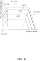
- FIG. 8 is a diagram showing a vehicle speed-HST input horsepower characteristic of the work vehicle 1 according to the present embodiment.
- H100 represents the vehicle speed-HST input horsepower characteristic when the accelerator operation amount is 100%.
- H80 represents the vehicle speed-HST input horsepower characteristic when the accelerator operation amount is 80%.
- H60 shows the vehicle speed-HST input horsepower characteristic when the accelerator operation amount is 60%.
- the controller 72 determines the target input horsepower to the HST 23 from the accelerator operation amount so that traveling performance (vehicle speed-HST input horsepower characteristic) corresponding to the accelerator operation amount can be obtained.
- the controller 72 determines the target input horsepower to the HST 23 in stalling (R_stall), the low vehicle speed range (RJow), the middle vehicle speed range (R_mid), and the high vehicle speed range (R_high) according to the target vehicle speed.
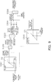
- FIG. 9 is a diagram showing processing for determining the target input horsepower to the HST 23 in stalling.
- the controller 72 determines a target traction force in stalling from the accelerator operation amount.
- the storage device 71 stores target traction data D2 that defines the relationship between the accelerator operation amount and the target traction force in stalling.
- the target traction data D2 defines the relationship between the accelerator operation amount and the target traction force in stalling in a normal state in which the above-described function such as traction control is not executed.
- the target traction data D2 defines the target traction force in stalling for the accelerator operation amount ranging from 0 to 100%. In the target traction data D2, the target traction force increases as the accelerator operation amount increases.
- the controller 72 refers to the target traction data D2 to determine the target traction force in stalling corresponding to the accelerator operation amount.
- step S302 the controller 72 determines the target traction force in stalling at each traction level by multiplying the target traction force in stalling determined in step S301 by the ratio according to the traction level.
- the ratio is 1 under the normal time where the traction control is not performed.
- step S303 the controller 72 converts the target traction force in stalling determined in step S302 into a target motor torque.
- the controller 72 calculates the target motor torque by multiplying the target traction force by a predetermined conversion factor and dividing by the transmission machine efficiency.
- the predetermined conversion factor is a factor for converting the traction force of the work vehicle 1 into a torque at the output shaft of the HST 23.
- the transmission machine efficiency is the transmission efficiency from the output shaft of the HST 23 to the traveling wheels 4.
- step S304 the controller 72 determines a target HST differential pressure from the target motor torque.
- the HST differential pressure is a difference between the hydraulic pressure of the first drive circuit 32a and the hydraulic pressure of the second drive circuit 32b.
- the controller 72 calculates the target HST differential pressure by dividing the target motor torque by the maximum displacement of the traveling motor 33 and dividing it by the torque efficiency of the traveling motor 33.
- step S305 the controller 72 determines the target flow rate of the traveling pump 31 from the target HST differential pressure.
- the controller 72 determines the leakage flow rate of the hydraulic fluid from the target HST differential pressure, and determines the target flow rate of the traveling pump 31 from the leakage flow rate.
- the storage device 71 stores leakage flow rate data D3 that defines the relationship between the target HST differential pressure and the leakage flow rate of the hydraulic fluid in the driving hydraulic circuit 32 in stalling.
- the leakage flow rate of the hydraulic fluid is the flow rate of hydraulic fluid leaking from the hydraulic equipment contained in HST23 and is correlated with the HST differential pressure. Therefore, the relationship between the HST differential pressure and the leakage flow rate of the hydraulic fluid in the driving hydraulic circuit 32 is previously obtained by experiment or simulation, and set as leakage flow rate data D10.
- the leakage flow rate of the hydraulic fluid corresponds to the flow rate of traveling pump 31 when the traveling pump 31 is driven with traveling motor 33 stopped in HST 23.
- the controller 72 refers to the leakage flow rate data D3 to determine the leakage flow rate corresponding to the target HST differential pressure. In stalling, the leakage flow rate substantially matches the flow rate of the traveling pump 31.
- the controller 72 determines the leakage flow rate obtained from the leakage flow rate data D3 as the target flow rate of the traveling pump 31.
- step S306 the controller 72 determines the target input horsepower to the HST 23 in stalling from the target HST differential pressure and the target flow rate of the traveling pump 31.
- the controller 72 multiplies the target HST differential pressure by the target flow rate of the traveling pump 31 and divides it by the pump torque efficiency to determine the target input horsepower to the HST 23 in stalling.
- FIG. 10 is a diagram showing processing for determining the target input horsepower to the HST 23 in the low vehicle speed range and the middle vehicle speed range.
- the controller 72 determines a target traveling horsepower from the target traction force in stalling and the target vehicle speed.
- the controller 72 determines the target traveling horsepower by multiplying the target traction force in stalling by the target vehicle speed and dividing by the transmission efficiency.
- the transmission efficiency is a transmission efficiency from the input shaft of the HST 23 to the traveling wheels 4.
- step S402 the controller 72 determines the target input horsepower to the HST 23 in the low vehicle speed range from the target traveling horsepower and the target input horsepower in stalling.
- the controller 72 determines the target input horsepower to the HST 23 in the low vehicle speed range by adding the target traveling horsepower to the target input horsepower in stalling.
- step S403 the controller 72 determines the target input horsepower to the HST 23 in the middle vehicle speed range from the accelerator operation amount.
- the storage device 71 stores target input horsepower data D4 that defines the relationship between the accelerator operation amount and the target input horsepower to the HST 23.
- the target input horsepower increases as the accelerator operation amount increases.
- the controller 72 refers to the target input horsepower data D4 to determine the target input horsepower in the middle vehicle speed range corresponding to the accelerator operation amount.
- step S404 the controller 72 determined the smaller one of the target input horsepower in the low vehicle speed range determined in step S402 and the target input horsepower in the middle vehicle speed range determined in step S403 as the target input horsepower to the HST 23 in the low / middle vehicle speed range.
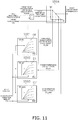
- FIG. 11 is a diagram showing processing for determining the target input horsepower to the HST 23 in the high vehicle speed range.
- the controller 72 determines the threshold vehicle speed in the high vehicle speed range from the accelerator operation amount and the shift position.
- the threshold vehicle speed in the high vehicle speed range is a vehicle speed indicative of the boundary between the low / middle vehicle speed range and the high vehicle speed range.
- the storage device 71 stores threshold vehicle speed data D6 that defines the relationship between the accelerator operation amount and the threshold vehicle speed.
- the threshold vehicle speed increases according to the increase of the accelerator operation amount.
- the threshold vehicle speed data D6 defines the relationship between the accelerator operation amount and the threshold vehicle speed for each shift position. Although the accelerator operation amount is the same, the threshold vehicle speed increases as the shift position is higher.
- the controller 72 refers to the threshold vehicle speed data D6 to determine the threshold vehicle speed corresponding to the accelerator operation amount and the shift position.
- step S502 the controller 72 determines the target reference vehicle speed from the accelerator operation amount and the shift position.
- the controller 72 determines the target reference vehicle speed corresponding to the accelerator operation amount and the shift position with reference to the reference vehicle speed data D1 described above.
- step S503 the controller 72 determines the zero traction vehicle speed from the accelerator operation amount and the shift position.
- the zero traction vehicle speed means the target vehicle speed when the traction force is zero, that is, when the traveling load is zero.
- the storage device 71 stores zero traction vehicle speed data D7 that defines the relationship between the accelerator operation amount and the zero traction vehicle speed. In the zero traction vehicle speed data D7, the zero traction vehicle speed increases in accordance with the increase in the accelerator operation amount.
- the zero traction vehicle speed data D7 defines the relationship between the accelerator operation amount and the zero traction vehicle speed for each shift position. Although the accelerator operation amount is the same, the zero traction vehicle speed increases as the shift position is higher.
- the controller 72 determines the zero traction vehicle speed corresponding to the accelerator operation amount and the shift position with reference to the zero traction vehicle speed data D7.
- the threshold vehicle speed data D6, the reference vehicle speed data D1, and the zero traction vehicle speed data D7 are set such that the target reference vehicle speed is greater than the threshold vehicle speed and lower than the zero traction vehicle speed.
- step S504 the controller 72 determines the static target input horsepower to the HST 23 from the target vehicle speed.
- the controller 72 determines the above-described target input horsepower in the low / middle vehicle speed range as the static target input horsepower.
- the controller 72 determines the target reference traveling horsepower calculated by multiplying the target reference traction force by the target reference vehicle speed as the static target input horsepower. For example, the controller determines the target reference traction force from the weight of the work vehicle 1 and a predetermined coefficient. The weight of the work vehicle 1 and the predetermined coefficient are stored in the storage device 71.
- the controller 72 sets the static target input horsepower to zero when the target vehicle speed is equal to or greater than the zero traction vehicle speed.
- the controller 72 determines the static target input horsepower to the HST 23 by linear interpolation.
- the static target input horsepower mentioned above is the target input horsepower to HST 23 at steady state.
- the controller 72 increases the target input horsepower to the HST 23 at a speed according to the accelerator operation amount within a range not exceeding the static target input horsepower.
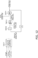
- FIG. 12 is a diagram showing processing for determining the target input horsepower (dynamic target input horsepower) to the HST 23 at the time of transition.
- step S601 the controller 72 determines the amount of increase in horsepower from the target acceleration described above, the actual vehicle speed, and the transmission efficiency.
- the amount of increase in horsepower means the amount of increase in input horsepower to HST 23 per unit time required to increase the vehicle speed at the target acceleration from the actual vehicle speed.
- step S602 the controller 72 determines the current target input horsepower by adding the amount of increase in horsepower to the previous target input horsepower.
- the controller 72 selects the larger of the current target input horsepower determined in step S602 and the above-described target input horsepower in stalling as the dynamic target input horsepower.
- the controller 72 selects the smaller one of the dynamic target input horsepower determined in step S603 and the static target input horsepower described above as the target input horsepower.
- the controller 72 determines the current dynamic target input horsepower by increasing the previous dynamic target input horsepower by the amount of horsepower increase corresponding to the accelerator operation amount. Then, the controller 72 increases the dynamic target input horsepower every unit time between the target input horsepower in stalling and the static target input horsepower.
- step S104 the controller 72 acquires the work implement operation amount.
- the controller 72 acquires the work implement operation amount from the signal from the work implement operation sensor 68.
- step S105 the controller 72 determines a target engine speed.
- the controller 72 determines the target engine speed from the target input horsepower to the HST 23 and the work implement operation amount.
- FIG. 13 is a diagram showing a process for determining the target engine speed.
- step S701 the controller 72 determines a target engine speed for the HST 23 from the target input horsepower determined in step S604.
- the storage device 71 stores engine torque-rotational speed data D8 that defines the relationship between the engine torque and the target engine speed for the HST 23.
- the controller 72 refers to the engine torque-rotational speed data D8 to determine the target engine speed corresponding to the target input horsepower to the HST 23.
- the controller 72 determines the target engine speed for the HST 23 such that the engine torque and the absorption torque of the traveling pump 31 coincide at a predetermined matching point MP on the equal horsepower line corresponding to the target input horsepower.
- step S702 the controller 72 determines a target engine speed for the work implement 3 from the work implement operation amount.
- the storage device 71 stores target rotational speed data D9 that defines the relationship between the work implement operation amount and the target engine speed for the work implement 3.
- the target engine speed increases as the work implement operation amount increases.
- the controller 72 refers to the target rotational speed data D9 to determine the target engine speed for the work implement 3 corresponding to the work implement operation amount.
- step S703 the controller 72 determines a target engine speed for vehicle speed from the target vehicle speed.
- the controller 72 determines a value calculated by multiplying the target vehicle speed by a predetermined conversion factor and the minimum transmission gear ratio as the target engine speed for the vehicle speed.
- the predetermined conversion factor is a factor for converting the target vehicle speed into the rotational speed of the output shaft of HST.
- the minimum transmission gear ratio is the minimum gear ratio of HST23.
- step S704 the controller 72 determines the target engine speed that is the maximum among the target engine speed for the HST 23, the target engine speed for the work implement 3, and the target engine speed for the vehicle speed.
- step S106 the controller 72 determines the target displacement of the traveling pump 31.
- the controller 72 determines the target displacement of the traveling pump 31 from the target vehicle speed and the target engine speed determined in step S704.
- step S107 the controller 72 determines the target displacement of the traveling motor 33.
- the controller 72 determines the target displacement of the traveling motor 33 from the target vehicle speed and the target engine speed determined in step S704.
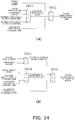
- FIG. 14A is a diagram showing a process for determining the target displacement of the traveling pump 31.
- the controller 72 determines the flow rate of the traveling motor 33 from the target vehicle speed.
- the controller 72 determines, as the flow rate of the traveling motor 33, a value obtained by multiplying the target vehicle speed by a predetermined conversion factor and the maximum displacement of the traveling motor 33, and dividing by the volumetric efficiency of the traveling motor 33.
- the predetermined conversion factor is a factor for converting the target vehicle speed into the rotational speed of the output shaft of the HST 23.
- step S802 the controller 72 determines the target displacement of the traveling pump 31 from the target engine speed and the flow rate of the traveling motor 33.
- the controller 72 calculates a value obtained by dividing the flow rate of the traveling motor 33 by the target engine speed and the volumetric efficiency of the traveling pump 31 as the target displacement of the traveling pump 31.
- FIG. 14B is a diagram showing a process for determining the target displacement of the traveling motor 33.
- the controller 72 determines the rotational speed of the traveling motor 33 from the target vehicle speed.
- the controller 72 calculates the rotational speed of the traveling motor 33 by multiplying the target vehicle speed by a predetermined conversion factor.
- the predetermined conversion factor is a factor for converting the target vehicle speed into the rotational speed of the output shaft of the HST 23.
- step S804 the controller 72 determines the flow rate of the traveling pump 31 from the target engine speed and the maximum displacement of the traveling pump 31.
- the controller 72 calculates the flow rate of the traveling pump 31 by dividing the value obtained by multiplying the engine speed by the maximum displacement of the traveling pump 31 by the volumetric efficiency of the traveling pump 31.
- step S805 the controller 72 determines the target displacement of the traveling motor 33 from the rotational speed of the traveling motor 33 and the flow rate of the traveling pump 31.
- the controller 72 divides the flow rate of the traveling pump 31 by the rotational speed of the traveling motor 33 and the volumetric efficiency of the traveling motor 33 to calculate the target displacement of the traveling motor 33.
- step S108 the controller 72 outputs a command signal.
- the controller 72 outputs a command signal to the fuel injector 24 to drive the engine 21 at the target engine speed.
- the controller 72 outputs a command signal to the pump displacement control device 45 to drive the traveling pump 31 at the target displacement.
- the controller 72 outputs a command signal to the motor displacement control device 35 to drive the traveling motor 33 at the target displacement.
- the leakage flow rate is determined from the target HST differential pressure by referring to the leakage flow rate data D3, and the target flow rate of the traveling pump 31 is determined from the leakage flow rate.
- the leakage flow rate from the driving hydraulic circuit 32 of HST23 is correlated with the HST differential pressure.
- the leakage flow rate substantially matches the flow rate of traveling pump 31. Accordingly, by referring to the leakage flow rate data D3, it is possible to accurately determine the target HST differential pressure, that is, the target flow rate of the traveling pump 31 corresponding to the target traction force. Thereby, the traction force in stalling can be controlled arbitrarily and precisely.
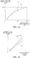
- FIG. 15 is a diagram showing an example of the target traction data D2 described above.
- a broken line C1 indicates the relationship between the accelerator operation amount and the actual traction force in stalling in the work vehicle according to the comparative example.
- the accelerator operation amount is an intermediate value AC1
- the actual traction force in stalling is maximum traction force Fmax
- the accelerator operation amount is AC1 or more
- the actual traction force in stalling is constant at the maximum traction force Fmax.
- the target traction data D2 is set such that the target traction force becomes the maximum traction force Fmax when the accelerator operation amount is AC2 larger than AC1.
- AC2 is more preferably, for example, 100%. It is preferable that the target traction force is linearly increased in accordance with an increase of the accelerator operation amount in the range of 0 to 100% of the accelerator operation amount.
- AC2 may be smaller than 100%.
- AC2 is preferably 80% or more.
- AC2 is preferably 90% or more.
- the operability of the traction force in stalling can be improved. Further, as described above, by determining the target flow rate of the traveling pump 31 with reference to the leakage flow rate data D3, the target traction force specified in the target traction data D2 can be realized with high accuracy. Furthermore, since the unnecessary increase in engine speed can be suppressed, fuel efficiency can be improved.
- the target traction force in stalling is corrected by multiplying the target traction force by the ratio according to the traction level. Then, the target differential pressure is determined from the corrected target traction force, and the target displacement of the traveling pump 31 is determined from the target differential pressure. Therefore, by controlling the displacement of the traveling pump 31 while maintaining the displacement of the traveling motor 33 at the maximum displacement, the maximum traction force according to the traction level can be realized. Thereby, the efficiency of the traveling motor 33 can be improved. Also, by referring to the leakage flow rate data D3, the target displacement of the traveling pump 31 is determined from the target differential pressure. Therefore, the maximum traction force according to the traction level can be realized with high accuracy.
- the work vehicle 1 is not limited to a wheel loader, and may be another type of vehicle such as a motor grader.
- the configurations of the drive system and control system of the work vehicle 1 are not limited to those of the above embodiment, and may be changed.
- the displacement of the traveling pump 31 may be controlled by another control valve, not limited to the pump control valve 47. That is, a control valve for controlling the pressure of the hydraulic fluid supplied to the pump control cylinder 46 via the pump pilot circuit 48 may be provided separately from the pump control valve 47.
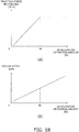
- the controller 72 may correct the above-mentioned leakage flow rate based on the temperature of the hydraulic fluid.
- the controller 72 obtains the temperature of the hydraulic fluid (hereinafter simply referred to as "oil temperature") supplied to the traveling motor 33 by the signal from the temperature sensor 49.
- the controller 72 may correct the leakage flow rate data according to the oil temperature. For example, as shown by the broken line D3' in FIG. 16 , the controller 72 may correct the leakage flow rate so as to increase the leakage flow rate in response to an increase in oil temperature. Alternatively, as shown by the broken line D3", the controller 72 may correct the leakage flow rate so as to decrease the leakage flow rate in response to the decrease in the oil temperature.
- the parameters used for the various operations described above are not limited to those described above, and may be changed. Alternatively, parameters other than the above-described parameters may be used for the calculation.
- the various data described above may be represented, for example, by an equation, or may be in the form of a table, a map, or the like.
- step S101 and step S104 may be executed in parallel.
- the controller 72 may determine the target vehicle speed by a method different from the above embodiment.
- the controller 72 may determine the target input horsepower to the HST 23 by a method different from the above embodiment.
- the controller 72 may determine the target engine speed by a method different from the above embodiment.
- the controller 72 may determine the target displacement of the traveling pump 31 by a method different from the above embodiment.
- the controller 72 may determine the target displacement of the traveling motor 33 by a method different from the above embodiment. Even in such a case, it is possible to accurately determine the target flow rate of the traveling pump 31 corresponding to the target HST differential pressure by using the leakage flow rate.
- the controller 72 increases the target input horsepower to the HST 23 every unit time between the target input horsepower in stalling and the static target input horsepower at the time of transition.
- the controller 72 may determine not only the target input horsepower in stalling but also another value corresponding to the accelerator operation amount as the lower limit of the target input horsepower to the HST 23.
- the traction force in stalling can be controlled arbitrarily, accurately and efficiently.
Claims (9)
- Véhicule de chantier (1) comprenant :un moteur (21) ;une transmission hydrostatique (23) incluant une pompe de déplacement (31) entraînée par le moteur (21), un circuit hydraulique (32) incluant un premier circuit pilote (32a) et un second circuit pilote (32b), le circuit hydraulique (32) étant connecté à la pompe de déplacement (31), et un moteur de déplacement (33) étant connecté à la pompe de déplacement (31) via le circuit hydraulique (32), un circuit fermé étant formé par la pompe de déplacement (31), le premier circuit pilote (32a), le second circuit pilote et le moteur de déplacement (33) ;un dispositif de stockage (71) stockant une donnée de débit de fuite définissant un relation entre une pression différentielle d'un fluide hydraulique entre le premier circuit pilote (32a) et le second circuit pilote et un débit de fuite du fluide hydraulique dans le circuit hydraulique (32) dans un état de calage ; etun contrôleur (72) en communication avec le dispositif de stockage (71), le contrôleur (72) étant configuré pourdéterminer une force de traction cible du véhicule,déterminer une pression différentielle cible qui est une valeur cible de la pression différentielle à partir de la force de traction cible,déterminer le débit de fuite à partir de la pression différentielle cible avec référence à la donnée de débit de fuite, etdéterminer un débit cible de la pompe de déplacement à partir du débit de fuite.
- Véhicule de chantier (1) selon la revendication 1, comprenant en outre :un accélérateur (61) ; etun capteur (64) qui sort un signal indicatif d'une amplitude d'actionnement de l'accélérateur (61), dans lequelle contrôleur (72) est configuré pourrecevoir le signal provenant du capteur (64), etdéterminer la force de traction cible à partir de l'amplitude d'actionnement de l'accélérateur (61).
- Véhicule de chantier (1) selon la revendication 2, dans lequel
le dispositif de stockage (71) stocke la donnée de traction cible qui définit une relation entre l'amplitude d'actionnement de l'accélérateur (61) et la force de traction cible, et
le contrôleur (72) est configuré pour déterminer la force de traction cible à partir de l'amplitude d'actionnement de l'accélérateur (61) avec référence à la donnée de traction cible. - Véhicule de chantier (1) selon l'une quelconque des revendications 1 à 3, dans lequel
le contrôleur (72) est configuré pourdéterminer un couple cible du moteur de déplacement (33) à partir de la force de traction cible, etdéterminer la pression différentielle cible à partir du couple cible et du déplacement du moteur de déplacement (33). - Véhicule de chantier (1) selon l'une quelconque des revendications 1 à 4, comprenant en outre :un capteur de température (49) qui sort un signal indicatif d'une température du fluide hydraulique dans le circuit hydraulique (32), dans lequelle contrôleur (72) est configuré pourrecevoir le signal provenant du capteur de température (49), etcorriger le débit de fuite en accord avec la température du fluide hydraulique.
- Véhicule de chantier (1) selon la revendication 5, dans lequel
le contrôleur (72) est configuré pour augmenter le débit de fuite en réponse à une augmentation dans la température du fluide hydraulique. - Véhicule de chantier (1) selon l'une quelconque des revendications 1 à 6, comprenant en outre :un dispositif d'entrée (69) destiné à sélectionner un niveau de traction, dans lequelle contrôleur (72) est configuré pourrecevoir un signal indicatif du niveau de traction sélectionné provenant du dispositif d'entrée (69),corriger la force de traction cible en accord avec le niveau de traction sélectionné, etdéterminer la pression différentielle cible à partir de la force de traction cible corrigée.
- Véhicule de chantier (1) selon l'une quelconque des revendications 1 à 7, dans lequel
le contrôleur (72) est configuré pourdéterminer une puissance d'entrée cible vers la transmission hydrostatique (23) à partir du débit cible de la pompe de déplacement (31), etdéterminer une vitesse de rotation cible du moteur (21) à partir de la puissance d'entrée cible. - Procédé exécuté par un contrôleur (72) pour commander un véhicule de chantier (1), le véhicule de chantier (1) incluant un moteur (21) et une transmission hydrostatique (23), la transmission hydrostatique (23) incluant une pompe de déplacement (31) entraînée par le moteur (21), un circuit hydraulique (32) connecté à la pompe de déplacement (31), un moteur de déplacement (33) connecté à la pompe de déplacement (31) via le circuit hydraulique (32), le circuit hydraulique (32) incluant un premier circuit pilote (32a) et un second circuit pilote (32b), un circuit fermé étant formé par la pompe de déplacement (31), le premier circuit pilote (32a), le second circuit pilote (32b) et le moteur de déplacement (33), le procédé comprenant les étapes consistant à :déterminer une force de traction cible du véhicule ;déterminer, à partir de la force de traction cible, une pression différentielle cible qui est une valeur cible de la pression différentielle d'un fluide hydraulique entre le premier circuit pilote (32a) et le second circuit pilote (32b) ;déterminer un débit de fuite à partir de la pression différentielle cible avec référence à une donnée de débit de fuite définissant une relation entre la pression différentielle et le débit de fuite du fluide hydraulique dans le circuit hydraulique (32) à l'état de calage ; etdéterminer un débit cible de la pompe de déplacement (31) à partir du débit de fuite.
Applications Claiming Priority (2)
| Application Number | Priority Date | Filing Date | Title |
|---|---|---|---|
| JP2017125377 | 2017-06-27 | ||
| PCT/JP2018/020537 WO2019003763A1 (fr) | 2017-06-27 | 2018-05-29 | Véhicule de travail et procédé de commande d'un véhicule de travail |
Publications (3)
| Publication Number | Publication Date |
|---|---|
| EP3553347A1 EP3553347A1 (fr) | 2019-10-16 |
| EP3553347A4 EP3553347A4 (fr) | 2020-09-30 |
| EP3553347B1 true EP3553347B1 (fr) | 2021-07-07 |
Family
ID=64740538
Family Applications (1)
| Application Number | Title | Priority Date | Filing Date |
|---|---|---|---|
| EP18823198.9A Active EP3553347B1 (fr) | 2017-06-27 | 2018-05-29 | Véhicule de travail et procédé de commande d'un véhicule de travail |
Country Status (5)
| Country | Link |
|---|---|
| US (1) | US11199260B2 (fr) |
| EP (1) | EP3553347B1 (fr) |
| JP (1) | JP7021210B2 (fr) |
| CN (1) | CN110199142B (fr) |
| WO (1) | WO2019003763A1 (fr) |
Families Citing this family (5)
| Publication number | Priority date | Publication date | Assignee | Title |
|---|---|---|---|---|
| US11459731B2 (en) * | 2019-10-28 | 2022-10-04 | Kubota Corporation | Working machine |
| DE102019218901A1 (de) * | 2019-12-04 | 2021-06-10 | Robert Bosch Gmbh | Fahrantrieb für ein Fahrzeug mit einem Fahrgetriebe und Steuerarchitektur zum Steuern des Fahrgetriebes |
| IT202000028574A1 (it) * | 2020-11-26 | 2022-05-26 | Cnh Ind Italia Spa | Trasmissione idrostatica per veicolo movimento terra fornita di un sistema di controllo basato su pressione e velocità |
| JP7424328B2 (ja) * | 2021-02-26 | 2024-01-30 | トヨタ自動車株式会社 | 変速機制御装置 |
| DE102022209502A1 (de) * | 2022-09-12 | 2024-03-14 | Zf Friedrichshafen Ag | Zugkraftführung zur Emulation eines Festganggetriebes |
Family Cites Families (16)
| Publication number | Priority date | Publication date | Assignee | Title |
|---|---|---|---|---|
| DE3713799A1 (de) * | 1987-04-24 | 1988-11-10 | Rexroth Mannesmann Gmbh | Hydrostatisches antriebssystem |
| US6164402A (en) * | 1998-11-18 | 2000-12-26 | Eaton Corporation | Control of pump for hydraulic front wheel drive |
| US7536856B2 (en) | 2005-11-30 | 2009-05-26 | Caterpillar Inc. | System for controlling a power output |
| US7739870B2 (en) * | 2006-08-04 | 2010-06-22 | Briggs And Stratton Corporation | Hydrostatic transmission |
| JP5074086B2 (ja) | 2007-04-26 | 2012-11-14 | 株式会社小松製作所 | 建設車両 |
| US7926267B2 (en) * | 2008-03-20 | 2011-04-19 | Caterpillar Inc. | Hystat transmission having pressure override control |
| DE102008059029A1 (de) * | 2008-11-26 | 2010-05-27 | Robert Bosch Gmbh | Leistungsverzweigungsgetriebe und Verfahren zu dessen Steuerung |
| US8165765B2 (en) | 2010-05-28 | 2012-04-24 | Caterpillar Inc. | Variator pressure-set torque control |
| JP5367853B2 (ja) * | 2012-01-23 | 2013-12-11 | 株式会社小松製作所 | モータグレーダ |
| JP5092060B1 (ja) | 2012-03-30 | 2012-12-05 | 株式会社小松製作所 | 作業車両及び作業車両の制御方法 |
| FR2993017B1 (fr) | 2012-07-03 | 2014-07-25 | Peugeot Citroen Automobiles Sa | Procede de regulation de pression hydraulique par une demande de debit, afin de recharger un accumulateur |
| FR3001774B1 (fr) * | 2013-02-04 | 2015-03-13 | Vianney Rabhi | Moteur-pompe hydraulique a cylindree fixe ou variable |
| JP6416787B2 (ja) | 2013-12-17 | 2018-10-31 | 株式会社小松製作所 | 作業車両及びその制御方法 |
| US9267597B2 (en) * | 2014-01-08 | 2016-02-23 | Allison Transmission, Inc. | System for adjusting fluid volume in a transmission and method thereof |
| JP6368495B2 (ja) | 2014-01-29 | 2018-08-01 | 株式会社小松製作所 | 作業車両及びその制御方法 |
| JP6364194B2 (ja) | 2014-01-29 | 2018-07-25 | 株式会社小松製作所 | 作業車両及びその制御方法 |
-
2018
- 2018-05-29 JP JP2019526714A patent/JP7021210B2/ja active Active
- 2018-05-29 CN CN201880007872.7A patent/CN110199142B/zh active Active
- 2018-05-29 WO PCT/JP2018/020537 patent/WO2019003763A1/fr unknown
- 2018-05-29 EP EP18823198.9A patent/EP3553347B1/fr active Active
- 2018-05-29 US US16/476,685 patent/US11199260B2/en active Active
Non-Patent Citations (1)
| Title |
|---|
| None * |
Also Published As
| Publication number | Publication date |
|---|---|
| WO2019003763A1 (fr) | 2019-01-03 |
| EP3553347A1 (fr) | 2019-10-16 |
| JP7021210B2 (ja) | 2022-02-16 |
| EP3553347A4 (fr) | 2020-09-30 |
| CN110199142B (zh) | 2020-12-01 |
| JPWO2019003763A1 (ja) | 2020-04-23 |
| US20210140541A1 (en) | 2021-05-13 |
| US11199260B2 (en) | 2021-12-14 |
| CN110199142A (zh) | 2019-09-03 |
Similar Documents
| Publication | Publication Date | Title |
|---|---|---|
| EP3553347B1 (fr) | Véhicule de travail et procédé de commande d'un véhicule de travail | |
| CN110214242B (zh) | 作业车辆、及作业车辆的控制方法 | |
| EP3553349B1 (fr) | Véhicule de chantier et son procédé de commande | |
| CN110914577B (zh) | 作业车辆及作业车辆的控制方法 | |
| JP7383104B2 (ja) | 作業車両、及び、作業車両の制御方法 | |
| WO2019163356A1 (fr) | Engin de chantier et procédé de commande d'engin de chantier |
Legal Events
| Date | Code | Title | Description |
|---|---|---|---|
| STAA | Information on the status of an ep patent application or granted ep patent |
Free format text: STATUS: THE INTERNATIONAL PUBLICATION HAS BEEN MADE |
|
| PUAI | Public reference made under article 153(3) epc to a published international application that has entered the european phase |
Free format text: ORIGINAL CODE: 0009012 |
|
| STAA | Information on the status of an ep patent application or granted ep patent |
Free format text: STATUS: REQUEST FOR EXAMINATION WAS MADE |
|
| 17P | Request for examination filed |
Effective date: 20190708 |
|
| AK | Designated contracting states |
Kind code of ref document: A1 Designated state(s): AL AT BE BG CH CY CZ DE DK EE ES FI FR GB GR HR HU IE IS IT LI LT LU LV MC MK MT NL NO PL PT RO RS SE SI SK SM TR |
|
| AX | Request for extension of the european patent |
Extension state: BA ME |
|
| A4 | Supplementary search report drawn up and despatched |
Effective date: 20200901 |
|
| DAV | Request for validation of the european patent (deleted) | ||
| DAX | Request for extension of the european patent (deleted) | ||
| RIC1 | Information provided on ipc code assigned before grant |
Ipc: F16H 61/472 20100101AFI20200826BHEP Ipc: F16H 61/431 20100101ALI20200826BHEP Ipc: F16H 61/421 20100101ALI20200826BHEP |
|
| REG | Reference to a national code |
Ref country code: DE Ref legal event code: R079 Ref document number: 602018019891 Country of ref document: DE Free format text: PREVIOUS MAIN CLASS: F16H0061403500 Ipc: F16H0061472000 |
|
| RIC1 | Information provided on ipc code assigned before grant |
Ipc: F16H 61/472 20100101AFI20201020BHEP Ipc: F16H 61/431 20100101ALI20201020BHEP Ipc: F16H 61/421 20100101ALI20201020BHEP |
|
| GRAP | Despatch of communication of intention to grant a patent |
Free format text: ORIGINAL CODE: EPIDOSNIGR1 |
|
| STAA | Information on the status of an ep patent application or granted ep patent |
Free format text: STATUS: GRANT OF PATENT IS INTENDED |
|
| INTG | Intention to grant announced |
Effective date: 20210112 |
|
| GRAS | Grant fee paid |
Free format text: ORIGINAL CODE: EPIDOSNIGR3 |
|
| GRAA | (expected) grant |
Free format text: ORIGINAL CODE: 0009210 |
|
| STAA | Information on the status of an ep patent application or granted ep patent |
Free format text: STATUS: THE PATENT HAS BEEN GRANTED |
|
| AK | Designated contracting states |
Kind code of ref document: B1 Designated state(s): AL AT BE BG CH CY CZ DE DK EE ES FI FR GB GR HR HU IE IS IT LI LT LU LV MC MK MT NL NO PL PT RO RS SE SI SK SM TR |
|
| REG | Reference to a national code |
Ref country code: GB Ref legal event code: FG4D |
|
| REG | Reference to a national code |
Ref country code: AT Ref legal event code: REF Ref document number: 1408902 Country of ref document: AT Kind code of ref document: T Effective date: 20210715 |
|
| REG | Reference to a national code |
Ref country code: DE Ref legal event code: R096 Ref document number: 602018019891 Country of ref document: DE |
|
| REG | Reference to a national code |
Ref country code: IE Ref legal event code: FG4D |
|
| REG | Reference to a national code |
Ref country code: SE Ref legal event code: TRGR |
|
| REG | Reference to a national code |
Ref country code: LT Ref legal event code: MG9D |
|
| REG | Reference to a national code |
Ref country code: NL Ref legal event code: MP Effective date: 20210707 |
|
| REG | Reference to a national code |
Ref country code: AT Ref legal event code: MK05 Ref document number: 1408902 Country of ref document: AT Kind code of ref document: T Effective date: 20210707 |
|
| PG25 | Lapsed in a contracting state [announced via postgrant information from national office to epo] |
Ref country code: RS Free format text: LAPSE BECAUSE OF FAILURE TO SUBMIT A TRANSLATION OF THE DESCRIPTION OR TO PAY THE FEE WITHIN THE PRESCRIBED TIME-LIMIT Effective date: 20210707 Ref country code: FI Free format text: LAPSE BECAUSE OF FAILURE TO SUBMIT A TRANSLATION OF THE DESCRIPTION OR TO PAY THE FEE WITHIN THE PRESCRIBED TIME-LIMIT Effective date: 20210707 Ref country code: ES Free format text: LAPSE BECAUSE OF FAILURE TO SUBMIT A TRANSLATION OF THE DESCRIPTION OR TO PAY THE FEE WITHIN THE PRESCRIBED TIME-LIMIT Effective date: 20210707 Ref country code: HR Free format text: LAPSE BECAUSE OF FAILURE TO SUBMIT A TRANSLATION OF THE DESCRIPTION OR TO PAY THE FEE WITHIN THE PRESCRIBED TIME-LIMIT Effective date: 20210707 Ref country code: NL Free format text: LAPSE BECAUSE OF FAILURE TO SUBMIT A TRANSLATION OF THE DESCRIPTION OR TO PAY THE FEE WITHIN THE PRESCRIBED TIME-LIMIT Effective date: 20210707 Ref country code: PT Free format text: LAPSE BECAUSE OF FAILURE TO SUBMIT A TRANSLATION OF THE DESCRIPTION OR TO PAY THE FEE WITHIN THE PRESCRIBED TIME-LIMIT Effective date: 20211108 Ref country code: NO Free format text: LAPSE BECAUSE OF FAILURE TO SUBMIT A TRANSLATION OF THE DESCRIPTION OR TO PAY THE FEE WITHIN THE PRESCRIBED TIME-LIMIT Effective date: 20211007 Ref country code: LT Free format text: LAPSE BECAUSE OF FAILURE TO SUBMIT A TRANSLATION OF THE DESCRIPTION OR TO PAY THE FEE WITHIN THE PRESCRIBED TIME-LIMIT Effective date: 20210707 Ref country code: BG Free format text: LAPSE BECAUSE OF FAILURE TO SUBMIT A TRANSLATION OF THE DESCRIPTION OR TO PAY THE FEE WITHIN THE PRESCRIBED TIME-LIMIT Effective date: 20211007 Ref country code: AT Free format text: LAPSE BECAUSE OF FAILURE TO SUBMIT A TRANSLATION OF THE DESCRIPTION OR TO PAY THE FEE WITHIN THE PRESCRIBED TIME-LIMIT Effective date: 20210707 |
|
| PG25 | Lapsed in a contracting state [announced via postgrant information from national office to epo] |
Ref country code: PL Free format text: LAPSE BECAUSE OF FAILURE TO SUBMIT A TRANSLATION OF THE DESCRIPTION OR TO PAY THE FEE WITHIN THE PRESCRIBED TIME-LIMIT Effective date: 20210707 Ref country code: LV Free format text: LAPSE BECAUSE OF FAILURE TO SUBMIT A TRANSLATION OF THE DESCRIPTION OR TO PAY THE FEE WITHIN THE PRESCRIBED TIME-LIMIT Effective date: 20210707 Ref country code: GR Free format text: LAPSE BECAUSE OF FAILURE TO SUBMIT A TRANSLATION OF THE DESCRIPTION OR TO PAY THE FEE WITHIN THE PRESCRIBED TIME-LIMIT Effective date: 20211008 |
|
| REG | Reference to a national code |
Ref country code: DE Ref legal event code: R097 Ref document number: 602018019891 Country of ref document: DE |
|
| PG25 | Lapsed in a contracting state [announced via postgrant information from national office to epo] |
Ref country code: DK Free format text: LAPSE BECAUSE OF FAILURE TO SUBMIT A TRANSLATION OF THE DESCRIPTION OR TO PAY THE FEE WITHIN THE PRESCRIBED TIME-LIMIT Effective date: 20210707 |
|
| PLBE | No opposition filed within time limit |
Free format text: ORIGINAL CODE: 0009261 |
|
| STAA | Information on the status of an ep patent application or granted ep patent |
Free format text: STATUS: NO OPPOSITION FILED WITHIN TIME LIMIT |
|
| PG25 | Lapsed in a contracting state [announced via postgrant information from national office to epo] |
Ref country code: SM Free format text: LAPSE BECAUSE OF FAILURE TO SUBMIT A TRANSLATION OF THE DESCRIPTION OR TO PAY THE FEE WITHIN THE PRESCRIBED TIME-LIMIT Effective date: 20210707 Ref country code: SK Free format text: LAPSE BECAUSE OF FAILURE TO SUBMIT A TRANSLATION OF THE DESCRIPTION OR TO PAY THE FEE WITHIN THE PRESCRIBED TIME-LIMIT Effective date: 20210707 Ref country code: RO Free format text: LAPSE BECAUSE OF FAILURE TO SUBMIT A TRANSLATION OF THE DESCRIPTION OR TO PAY THE FEE WITHIN THE PRESCRIBED TIME-LIMIT Effective date: 20210707 Ref country code: EE Free format text: LAPSE BECAUSE OF FAILURE TO SUBMIT A TRANSLATION OF THE DESCRIPTION OR TO PAY THE FEE WITHIN THE PRESCRIBED TIME-LIMIT Effective date: 20210707 Ref country code: CZ Free format text: LAPSE BECAUSE OF FAILURE TO SUBMIT A TRANSLATION OF THE DESCRIPTION OR TO PAY THE FEE WITHIN THE PRESCRIBED TIME-LIMIT Effective date: 20210707 Ref country code: AL Free format text: LAPSE BECAUSE OF FAILURE TO SUBMIT A TRANSLATION OF THE DESCRIPTION OR TO PAY THE FEE WITHIN THE PRESCRIBED TIME-LIMIT Effective date: 20210707 |
|
| 26N | No opposition filed |
Effective date: 20220408 |
|
| PG25 | Lapsed in a contracting state [announced via postgrant information from national office to epo] |
Ref country code: IT Free format text: LAPSE BECAUSE OF FAILURE TO SUBMIT A TRANSLATION OF THE DESCRIPTION OR TO PAY THE FEE WITHIN THE PRESCRIBED TIME-LIMIT Effective date: 20210707 |
|
| REG | Reference to a national code |
Ref country code: CH Ref legal event code: PL |
|
| REG | Reference to a national code |
Ref country code: BE Ref legal event code: MM Effective date: 20220531 |
|
| GBPC | Gb: european patent ceased through non-payment of renewal fee |
Effective date: 20220529 |
|
| PG25 | Lapsed in a contracting state [announced via postgrant information from national office to epo] |
Ref country code: MC Free format text: LAPSE BECAUSE OF FAILURE TO SUBMIT A TRANSLATION OF THE DESCRIPTION OR TO PAY THE FEE WITHIN THE PRESCRIBED TIME-LIMIT Effective date: 20210707 Ref country code: LU Free format text: LAPSE BECAUSE OF NON-PAYMENT OF DUE FEES Effective date: 20220529 Ref country code: LI Free format text: LAPSE BECAUSE OF NON-PAYMENT OF DUE FEES Effective date: 20220531 Ref country code: CH Free format text: LAPSE BECAUSE OF NON-PAYMENT OF DUE FEES Effective date: 20220531 |
|
| PG25 | Lapsed in a contracting state [announced via postgrant information from national office to epo] |
Ref country code: IE Free format text: LAPSE BECAUSE OF NON-PAYMENT OF DUE FEES Effective date: 20220529 Ref country code: FR Free format text: LAPSE BECAUSE OF NON-PAYMENT OF DUE FEES Effective date: 20220531 |
|
| PG25 | Lapsed in a contracting state [announced via postgrant information from national office to epo] |
Ref country code: GB Free format text: LAPSE BECAUSE OF NON-PAYMENT OF DUE FEES Effective date: 20220529 Ref country code: BE Free format text: LAPSE BECAUSE OF NON-PAYMENT OF DUE FEES Effective date: 20220531 |
|
| PGFP | Annual fee paid to national office [announced via postgrant information from national office to epo] |
Ref country code: DE Payment date: 20230404 Year of fee payment: 6 |
|
| PGFP | Annual fee paid to national office [announced via postgrant information from national office to epo] |
Ref country code: SE Payment date: 20230412 Year of fee payment: 6 |
|
| PG25 | Lapsed in a contracting state [announced via postgrant information from national office to epo] |
Ref country code: HU Free format text: LAPSE BECAUSE OF FAILURE TO SUBMIT A TRANSLATION OF THE DESCRIPTION OR TO PAY THE FEE WITHIN THE PRESCRIBED TIME-LIMIT; INVALID AB INITIO Effective date: 20180529 |