EP3832149A1 - Cable staple assembly - Google Patents
Cable staple assembly Download PDFInfo
- Publication number
- EP3832149A1 EP3832149A1 EP20208233.5A EP20208233A EP3832149A1 EP 3832149 A1 EP3832149 A1 EP 3832149A1 EP 20208233 A EP20208233 A EP 20208233A EP 3832149 A1 EP3832149 A1 EP 3832149A1
- Authority
- EP
- European Patent Office
- Prior art keywords
- staple
- insulator
- profile
- crown
- cable
- Prior art date
- Legal status (The legal status is an assumption and is not a legal conclusion. Google has not performed a legal analysis and makes no representation as to the accuracy of the status listed.)
- Pending
Links
Images


Classifications
-
- F—MECHANICAL ENGINEERING; LIGHTING; HEATING; WEAPONS; BLASTING
- F16—ENGINEERING ELEMENTS AND UNITS; GENERAL MEASURES FOR PRODUCING AND MAINTAINING EFFECTIVE FUNCTIONING OF MACHINES OR INSTALLATIONS; THERMAL INSULATION IN GENERAL
- F16B—DEVICES FOR FASTENING OR SECURING CONSTRUCTIONAL ELEMENTS OR MACHINE PARTS TOGETHER, e.g. NAILS, BOLTS, CIRCLIPS, CLAMPS, CLIPS OR WEDGES; JOINTS OR JOINTING
- F16B15/00—Nails; Staples
- F16B15/08—Nails; Staples formed in integral series but easily separable
-
- F—MECHANICAL ENGINEERING; LIGHTING; HEATING; WEAPONS; BLASTING
- F16—ENGINEERING ELEMENTS AND UNITS; GENERAL MEASURES FOR PRODUCING AND MAINTAINING EFFECTIVE FUNCTIONING OF MACHINES OR INSTALLATIONS; THERMAL INSULATION IN GENERAL
- F16B—DEVICES FOR FASTENING OR SECURING CONSTRUCTIONAL ELEMENTS OR MACHINE PARTS TOGETHER, e.g. NAILS, BOLTS, CIRCLIPS, CLAMPS, CLIPS OR WEDGES; JOINTS OR JOINTING
- F16B15/00—Nails; Staples
- F16B15/0015—Staples
-
- H—ELECTRICITY
- H01—ELECTRIC ELEMENTS
- H01B—CABLES; CONDUCTORS; INSULATORS; SELECTION OF MATERIALS FOR THEIR CONDUCTIVE, INSULATING OR DIELECTRIC PROPERTIES
- H01B17/00—Insulators or insulating bodies characterised by their form
- H01B17/56—Insulating bodies
- H01B17/66—Joining insulating bodies together, e.g. by bonding
-
- H—ELECTRICITY
- H02—GENERATION; CONVERSION OR DISTRIBUTION OF ELECTRIC POWER
- H02G—INSTALLATION OF ELECTRIC CABLES OR LINES, OR OF COMBINED OPTICAL AND ELECTRIC CABLES OR LINES
- H02G3/00—Installations of electric cables or lines or protective tubing therefor in or on buildings, equivalent structures or vehicles
- H02G3/26—Installations of cables, lines, or separate protective tubing therefor directly on or in walls, ceilings, or floors
-
- H—ELECTRICITY
- H02—GENERATION; CONVERSION OR DISTRIBUTION OF ELECTRIC POWER
- H02G—INSTALLATION OF ELECTRIC CABLES OR LINES, OR OF COMBINED OPTICAL AND ELECTRIC CABLES OR LINES
- H02G3/00—Installations of electric cables or lines or protective tubing therefor in or on buildings, equivalent structures or vehicles
- H02G3/30—Installations of cables or lines on walls, floors or ceilings
- H02G3/32—Installations of cables or lines on walls, floors or ceilings using mounting clamps
-
- B—PERFORMING OPERATIONS; TRANSPORTING
- B25—HAND TOOLS; PORTABLE POWER-DRIVEN TOOLS; MANIPULATORS
- B25C—HAND-HELD NAILING OR STAPLING TOOLS; MANUALLY OPERATED PORTABLE STAPLING TOOLS
- B25C5/00—Manually operated portable stapling tools; Hand-held power-operated stapling tools; Staple feeding devices therefor
- B25C5/16—Staple-feeding devices, e.g. with feeding means, supports for staples or accessories concerning feeding devices
- B25C5/1665—Staple-feeding devices, e.g. with feeding means, supports for staples or accessories concerning feeding devices with means for preventing jamming or aiding unjamming within the drive channel
Definitions
- the present disclosure relates to cable staple assemblies provided in stick form for use with a staple driving tool.
- Cable staple assemblies provided in stick form typically include frangible connectors between adjacent pairs of connectors.
- frangible connectors between it and the second staple are broken.
- the frangible connectors that are broken in a driving operation are only on the trailing side of the lead staple subassembly.
- the breaking of the frangible connectors can cause problematic counterclockwise rotation of the lead staple subassembly as it travels through the drive channel of the tool. It would be desirable to provide a consistent, reliable way of causing the lead staple subassembly to either remain aligned with, or to rotate slightly clockwise (which is much less problematic), as it travels through the drive channel of the tool.
- the depth to which a staple is driven by a staple driving tool can be impacted by various parameters, including wood type/density, grain location, tool nose position, and insulator attachment strength.
- the staple insulator can be driven too shallowly or too deeply, which can unduly bite into the outer insulation of the electrical cable and damage or otherwise compromise the integrity of the electrical wiring. It would be desirable to provide a consistent, reliable way of snugging the staple insulator against the electrical cable without unduly biting into the cable over a large range of variations in the depth to which a staple is driven.
- a cable staple assembly for use with a staple driving tool having a driver and a cooperating breaking portion.
- the cable staple assembly can include a plurality of insulator bodies having frangible connectors extending between adjacent pairs of the insulator bodies.
- Each of the insulator bodies can have a counteracting frangible portion, and an insulator bridge extending between a pair of leg recesses.
- the frangible connectors alone can extend between and couple the plurality of insulator bodies together into a strip.
- Each counteracting frangible portion can be spaced from the frangible connectors and can be coupled solely to a single one of the plurality of insulator bodies.
- the cable staple assembly can include a plurality of staples. Each staple can have a pair of legs extending from opposite ends of a staple crown with the pair of legs being received in the pair of leg recesses of one of the insulator bodies.
- a cable staple assembly can include a plurality of insulator bodies frangibly coupled together into a strip. Each insulator body can have an insulator bridge extending between a pair of leg recesses. The insulator bridge can have an upper bridge profile.
- the cable staple assembly can include a plurality of staples. Each staple can have a pair of legs extending from opposite ends of a staple crown that has a lower crown profile with the pair of legs received in a respective pair of leg recesses of one of the insulator bodies and with the lower crown profile opposing the upper bridge profile.
- the lower crown profile and the upper bridge profile can have opposite end portions engaging each other adjacent the opposite ends of the staple crown.
- the lower crown profile and the upper bridge profile can also have central portions spaced from each other between the engaging opposite end portions to provide a central space between corresponding central portions of the insulator bridge and the staple crown.
- Figs. 1-7 illustrate one example embodiment of a cable staple assembly 20 in accordance with the present disclosure.
- This example cable staple assembly 20 generally includes a plurality of insulator bodies 22 and a plurality of staples 24.
- the insulator bodies 22 can have frangible connectors 26 that extend between and couple adjacent pairs of the plurality of insulator bodies 22 together into a strip 28.
- each frangible connector 26 is coupled at its ends to different, adjacent ones of insulator bodies 22.
- Each insulator body 22 can additionally also include at least one counteracting frangible portion 30 that is separate or spaced from, or independent of, the frangible connectors 26. Breaking the frangible connectors 26 between an adjacent pair of insulator bodies 22 alone is sufficient to separate the adjacent pair of insulator bodies 22 from each other. In contrast, breaking the counteracting frangible portions 30 does not result in separation of the adjacent pairs of insulator bodies 22. This is because the counteracting frangible portions 30 are not coupled at ends to adjacent insulator bodies 22 like the coupling frangible connectors 26. Each counteracting frangible portions 30 is coupled solely to a single one of the insulator bodies 22. For example, both ends of the counteracting frangible portions 30 are coupled to the same insulator body 22.
- the counteracting frangible portions 30 can extend longitudinally between opposite connected ends in a portion direction that is substantially parallel to direction or plane 70, which extends substantially parallel to the longitudinal leading and trailing sides 36 and 34, respectively, of the insulator bodies 22.
- the counteracting frangible portions 30 can be designed to shear or break across a portion cross-section generally indicated by plane 68, which extends substantially perpendicular to the longitudinal leading and trailing sides 36 and 34, respectively, of the insulator bodies 22.
- a recess 84 can be provided in the longitudinal leading side 36 of the insulator body 22 and a corresponding counteracting frangible portion 30 can span across an upper end of each recess 84. Opposite ends of each counteracting frangible portion 30 can be connected to opposite sides of the corresponding recess 84.
- each leading side 36 of each insulator body 22 can include multiple counteracting frangible portions 30.
- each leading side 36 can include two counteracting frangible portions 30, and the counteracting frangible portions 30 can be positioned equidistant from or balanced around a longitudinal center of the longitudinal leading side 36 of each insulator body 22.
- the sides 36 and 38 of each insulator body 22 can include multiple frangible connectors 26, and the frangible connectors of each longitudinal side can be positioned equidistant from or balanced around a longitudinal center of the longitudinal leading side of each insulator body 22.
- the sides of each insulator body 22 can include five frangible connectors 26, with two pairs balanced around a longitudinal center of the longitudinal side of each insulator body 22, and one positioned on the longitudinal center.
- the frangible connectors 26 can extend longitudinally between opposite connected ends in a connector direction that is substantially parallel to direction or plane 68, which extends substantially perpendicular to the longitudinal leading and trailing sides 36 and 34, respectively, of the insulator bodies 22.
- the frangible connectors 26 can be designed to break across a connector cross-section generally indicated by plane 70, which extends substantially parallel to the longitudinal leading and trailing sides 36 and 34, respectively, of the insulator bodies 22.
- the frangible connector 26 and counteracting frangible portions 30 can extend in longitudinal directions that are substantially perpendicular to each other, and can be designed to break across cross-sections that are substantially perpendicular to each other.
- the insulator bodies 22 of the example embodiment are symmetrical so that either end of the cable staple assembly 20 can be inserted into a staple driving tool 32 as the leading end.
- the frangible connectors 26 are provided on the trailing side 34 of each connector body 22, while the counteracting frangible portions 30 are provided on the opposite, leading side 36 of each connector body 22.
- the dual breaking or shearing of the frangible connectors 26 and the counteracting frangible portions 30 on opposite sides of the insulator bodies 22 as the lead subassembly 38 is driven from the tool 32 can counteract problematic rotation of the lead staple and connector body sub-assembly 38 within the drive channel 76 of the tool 32, as described hereinafter.
- Each insulator body 22 can have an insulator bridge 42 extending between a pair of leg recesses 40.
- Each staple 24 has a pair of legs 48 that extend from opposite ends of a staple crown 50. The legs 48 are respectively received in the leg recesses 40 of one of the insulator bodies 22.
- An upper end of each leg recess 40 can provide a narrowed portion or pinch point 46 that engages against the staple legs 48 adjacent where the crown 50 and legs 48 meet. The narrowed portions 46 can frictionally engage the staple legs 48 to help retain the position of the insulator body 22 relative to the staple 24 in a shipping configuration.
- the insulator body 22 can be positioned and retained at an upper end of the staple 24, with the insulator bridge 42 receiving or engaging the staple crown 50 so that all of the driving force of the tool 32 goes to setting the staple 24 and not to also sliding the insulator body 22 from a bottom end to the top end of the staple 24.
- Outer lateral sides 52 of the leg recesses 40 of the insulator body 22 can be tapered laterally outwardly and downwardly from the narrowed portion or pinch point 46 to facilitate outward rotation or pivoting of the insulator legs 66 and arching of the insulator bridge 42 as described hereinafter.
- the insulator bridge 42 can have an upper bridge profile 44 defined by an upper surface of the insulator bridge 50.
- the staple crown 50 can have a lower crown profile 54 defined by a lowermost surface of the staple crown 50 that is directly adjacent to, and directly opposing the upper surface or upper bridge profile 44.
- the upper bridge profile 44 can be defined by two raised end portions 56 and/or a recessed or lowered central portion 58 extending between the two raised end portions 56.
- the lower crown profile 54 of the staple 24 can extend between and along the opposite ends 60 and can be substantially linear, planar or flat.
- the lower crown profile 54 and the upper bridge profile 44 can have opposite end portions 58 and 60, respectively, that engage against each other adjacent the opposite ends of the staple crown 50 while central portions 58 and 62 are spaced from each other to provide a central space 64 between central portions 58 and 62 of the insulator bridge 42 and the staple crown 50.
- This central space 64 enables the central portion 58 of the bridge 42, including its upper bridge surface or profile 44, to arch upwardly without engaging against the adjacent, opposing central portion 62 of the staple crown 50, including its lower crown surface or profile 54.
- the cable staple assembly 20 can further be designed to interact with the cable staple driving tool 32 and a cable 72 as described herein.
- the cable staple driving tool 32 can include a nosepiece 78 including a driver 74 and a drive path or channel 76.
- the nosepiece 78 can additionally include at least one cooperating breaking portion 80.
- the cooperating breaking portion 80 can be in the form of two protrusions 82. As the lead staple and connector body sub-assembly 38 is moved into position or alignment with the drive channel 76, the cooperating breaking portion 80 is received within the recess 84 of the leading side 36 of the insulator body 22.
- the protrusion 82 When initially received within the recess 84 of the insulator body 22, the protrusion 82 can be vertically spaced from the corresponding counteracting frangible portion 30, leaving a vertical gap 86 therebetween.
- the counteracting frangible portion 30 is designed to be spaced from the cooperating breaking portion 80 of the staple driving tool 32 during an initial period of the staple setting operation of the tool.
- the driver 74 engages the staple 24.
- the resulting movement of the lead staple and connector body sub-assembly 38 can initially act upon the frangible connectors 22, but not on the counteracting frangible portions 30 until the lead sub-assembly 38 moves sufficiently to close the gap 86.
- the counteracting frangible portions 30 are independent of the frangible connectors 26 as noted above, they have not been impacted or modified by the separation of the prior adjacent insulator and staple subassembly at the point in time that each subassembly becomes the lead subassembly 38 within the staple driving tool 32.
- both the relevant frangible connectors 26 and counteracting frangible portions 30 of the lead staple subassembly 38 remain in their original or designed state.
- both the relevant frangible connectors 26 and counteracting frangible portions 30 of the lead subassembly 38 retain their original designed force required to break or shear them. This makes the behavior of both the relevant frangible connectors 26 and counteracting frangible portions 30 much more predictable.
- the relative balancing of the forces on opposite sides 34 and 36 of the lead subassembly 38 as the relevant frangible connectors 26 and counteracting frangible portions 30 are broken or sheared can be reliably controlled, known, and repeatably provided.
- the staple 24 can be designed to transfer a driving force from the driver 74 to the insulator body 22 by engagement of the lower crown profile 54 of the staple 24 against the upper bridge profile 44 of the insulator body 22.
- the electrical cable 72 can engage an underside of the central portion 58 of the insulator bridge 42.
- the central portion 58 of the insulator bridge 42 can be deformable by arching upward toward the central portion 52 of the staple crown 50 without the central portions contacting each other, at least until the space 64 closes.
- the insulator legs 66 can rotate inwardly toward each other at their lower ends 90.
- the outwardly and downwardly tapered outer lateral sides 52 can provide a space or gap between the outer side of the staple leg 48 and the corresponding outer lateral side 52 of the leg recess 40 at the lower end 90 of the insulator leg 66.
- the insulator legs 66 can rotate inwardly toward each other at their lower ends 90 without contacting the tapered outer lateral sides 52, at least initially. This can facilitate rotational movement of the insulator legs 66 as the central portion 58 of the insulator bridge 42 arches upwardly toward the staple crown 50.
- designing the insulator bridge 42 to be deformable upwardly toward the staple crown 50 and into the central space 64 reduces the biting force of the insulator body 22 on the electrical cable 72.
- the deformation of the insulator bridge 42 operates like a spring, reducing the force on the electrical cable 72, while allowing the staple legs 48 to move deeper into the base 88.
- designing the lower ends 90 of the insulator legs 66 to be rotatable toward the corresponding staple legs 48 and into a space 92 provided therebetween by the tapered outer lateral sides 52 of the leg recess 40 can also reduce the biting force of the insulator body on the electrical cable 72.
- this operates like a reduction in the spring constant of the insulator bridge 42, reducing the biting force of the insulator body 22 on the electrical cable 72, while allowing the staple legs 48 to move deeper into the base 88.
- these can individually and collectively provide a broader range of driver force settings of the staple driving tool 32 that are large enough to hold the electrical cable 72, but not so large that the insulator body 22 problematically bites into the electrical cable 72 and damages it.
Landscapes
- Engineering & Computer Science (AREA)
- General Engineering & Computer Science (AREA)
- Mechanical Engineering (AREA)
- Architecture (AREA)
- Civil Engineering (AREA)
- Structural Engineering (AREA)
- Installation Of Indoor Wiring (AREA)
Abstract
Description
- The present disclosure relates to cable staple assemblies provided in stick form for use with a staple driving tool.
- This section provides background information related to the present disclosure which is not necessarily prior art.
- Cable staple assemblies provided in stick form typically include frangible connectors between adjacent pairs of connectors. As a lead staple subassembly in a staple driving tool is driven, the frangible connectors between it and the second staple are broken. The frangible connectors that are broken in a driving operation are only on the trailing side of the lead staple subassembly. Thus, the breaking of the frangible connectors can cause problematic counterclockwise rotation of the lead staple subassembly as it travels through the drive channel of the tool. It would be desirable to provide a consistent, reliable way of causing the lead staple subassembly to either remain aligned with, or to rotate slightly clockwise (which is much less problematic), as it travels through the drive channel of the tool.
- The depth to which a staple is driven by a staple driving tool can be impacted by various parameters, including wood type/density, grain location, tool nose position, and insulator attachment strength. Depending on how the user adjusts the depth of drive setting on the tool or holds the tool relative to the work surface, the staple insulator can be driven too shallowly or too deeply, which can unduly bite into the outer insulation of the electrical cable and damage or otherwise compromise the integrity of the electrical wiring. It would be desirable to provide a consistent, reliable way of snugging the staple insulator against the electrical cable without unduly biting into the cable over a large range of variations in the depth to which a staple is driven.
- This section provides a general summary of the disclosure, and is not a comprehensive disclosure of its full scope or all of its features.
- In accordance with one aspect of the present disclosure, a cable staple assembly for use with a staple driving tool having a driver and a cooperating breaking portion can be provided. The cable staple assembly can include a plurality of insulator bodies having frangible connectors extending between adjacent pairs of the insulator bodies. Each of the insulator bodies can have a counteracting frangible portion, and an insulator bridge extending between a pair of leg recesses. The frangible connectors alone can extend between and couple the plurality of insulator bodies together into a strip. Each counteracting frangible portion can be spaced from the frangible connectors and can be coupled solely to a single one of the plurality of insulator bodies. In addition, the cable staple assembly can include a plurality of staples. Each staple can have a pair of legs extending from opposite ends of a staple crown with the pair of legs being received in the pair of leg recesses of one of the insulator bodies.
- In accordance with another aspect of the present disclosure, a cable staple assembly can include a plurality of insulator bodies frangibly coupled together into a strip. Each insulator body can have an insulator bridge extending between a pair of leg recesses. The insulator bridge can have an upper bridge profile. In addition, the cable staple assembly can include a plurality of staples. Each staple can have a pair of legs extending from opposite ends of a staple crown that has a lower crown profile with the pair of legs received in a respective pair of leg recesses of one of the insulator bodies and with the lower crown profile opposing the upper bridge profile. The lower crown profile and the upper bridge profile can have opposite end portions engaging each other adjacent the opposite ends of the staple crown. The lower crown profile and the upper bridge profile can also have central portions spaced from each other between the engaging opposite end portions to provide a central space between corresponding central portions of the insulator bridge and the staple crown.
- Further areas of applicability will become apparent from the description provided herein. The description and specific examples in this summary are intended for purposes of illustration only and are not intended to limit the scope of the present disclosure.
- The drawings described herein are for illustrative purposes only of selected embodiments and not all possible implementations, and are not intended to limit the scope of the present disclosure.
-
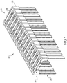
Fig. 1 is a perspective view of one example embodiment of a cable staple assembly for use with a staple driving tool in accordance with the present disclosure. -
Fig.2 is a perspective view of one of the insulator bodies of the cable staple assembly ofFig. 1 . -
Fig. 3A is a partial cross-sectional view of a lead end of the cable staple assembly ofFig. 1 mounted in the nosepiece of a staple driving tool. -
Fig. 3B Is an enlarged portion of theFig. 3A . -
Fig. 4 is a partial top plan view of a leading end of the cable staple assembly ofFig. 1 . -
Fig. 5 is a partial cross-sectional exploded view of the cable staple assembly ofFig. 1 . -
Fig. 6 is a cross-sectional view of the cable staple assembly ofFig. 1 in a pre-driven, shipping or undeformed state. -
Fig. 7 is a cross-sectional view of the cable staple assembly ofFig. 1 in a post-driven, deployed or deformed state. - Corresponding reference numerals indicate corresponding parts throughout the several views of the drawings.
- Example embodiments will now be described more fully with reference to the accompanying drawings.
-
Figs. 1-7 illustrate one example embodiment of acable staple assembly 20 in accordance with the present disclosure. This examplecable staple assembly 20 generally includes a plurality ofinsulator bodies 22 and a plurality ofstaples 24. Theinsulator bodies 22 can havefrangible connectors 26 that extend between and couple adjacent pairs of the plurality ofinsulator bodies 22 together into astrip 28. Thus, eachfrangible connector 26 is coupled at its ends to different, adjacent ones ofinsulator bodies 22. - Each
insulator body 22 can additionally also include at least one counteractingfrangible portion 30 that is separate or spaced from, or independent of, thefrangible connectors 26. Breaking thefrangible connectors 26 between an adjacent pair ofinsulator bodies 22 alone is sufficient to separate the adjacent pair ofinsulator bodies 22 from each other. In contrast, breaking the counteractingfrangible portions 30 does not result in separation of the adjacent pairs ofinsulator bodies 22. This is because the counteractingfrangible portions 30 are not coupled at ends toadjacent insulator bodies 22 like the couplingfrangible connectors 26. Each counteractingfrangible portions 30 is coupled solely to a single one of theinsulator bodies 22. For example, both ends of the counteractingfrangible portions 30 are coupled to thesame insulator body 22. - The counteracting
frangible portions 30 can extend longitudinally between opposite connected ends in a portion direction that is substantially parallel to direction orplane 70, which extends substantially parallel to the longitudinal leading and trailingsides insulator bodies 22. The counteractingfrangible portions 30 can be designed to shear or break across a portion cross-section generally indicated byplane 68, which extends substantially perpendicular to the longitudinal leading and trailingsides insulator bodies 22. For example, arecess 84 can be provided in the longitudinal leadingside 36 of theinsulator body 22 and a corresponding counteractingfrangible portion 30 can span across an upper end of eachrecess 84. Opposite ends of each counteractingfrangible portion 30 can be connected to opposite sides of thecorresponding recess 84. - As in the illustrated embodiment, the leading
side 36 of eachinsulator body 22 can include multiple counteractingfrangible portions 30. For example, each leadingside 36 can include two counteractingfrangible portions 30, and the counteractingfrangible portions 30 can be positioned equidistant from or balanced around a longitudinal center of the longitudinal leadingside 36 of eachinsulator body 22. Similarly, thesides insulator body 22 can include multiplefrangible connectors 26, and the frangible connectors of each longitudinal side can be positioned equidistant from or balanced around a longitudinal center of the longitudinal leading side of eachinsulator body 22. For example, the sides of eachinsulator body 22 can include fivefrangible connectors 26, with two pairs balanced around a longitudinal center of the longitudinal side of eachinsulator body 22, and one positioned on the longitudinal center. - The
frangible connectors 26 can extend longitudinally between opposite connected ends in a connector direction that is substantially parallel to direction orplane 68, which extends substantially perpendicular to the longitudinal leading and trailingsides insulator bodies 22. Thefrangible connectors 26 can be designed to break across a connector cross-section generally indicated byplane 70, which extends substantially parallel to the longitudinal leading and trailingsides insulator bodies 22. Thus, thefrangible connector 26 and counteractingfrangible portions 30 can extend in longitudinal directions that are substantially perpendicular to each other, and can be designed to break across cross-sections that are substantially perpendicular to each other. - The
insulator bodies 22 of the example embodiment are symmetrical so that either end of thecable staple assembly 20 can be inserted into astaple driving tool 32 as the leading end. In any event, thefrangible connectors 26 are provided on the trailingside 34 of eachconnector body 22, while the counteractingfrangible portions 30 are provided on the opposite, leadingside 36 of eachconnector body 22. The dual breaking or shearing of thefrangible connectors 26 and the counteractingfrangible portions 30 on opposite sides of theinsulator bodies 22 as thelead subassembly 38 is driven from thetool 32 can counteract problematic rotation of the lead staple andconnector body sub-assembly 38 within the drive channel 76 of thetool 32, as described hereinafter. - Each
insulator body 22 can have aninsulator bridge 42 extending between a pair of leg recesses 40. Eachstaple 24 has a pair oflegs 48 that extend from opposite ends of astaple crown 50. Thelegs 48 are respectively received in the leg recesses 40 of one of theinsulator bodies 22. An upper end of eachleg recess 40 can provide a narrowed portion orpinch point 46 that engages against thestaple legs 48 adjacent where thecrown 50 andlegs 48 meet. The narrowedportions 46 can frictionally engage thestaple legs 48 to help retain the position of theinsulator body 22 relative to the staple 24 in a shipping configuration. For example, theinsulator body 22 can be positioned and retained at an upper end of the staple 24, with theinsulator bridge 42 receiving or engaging thestaple crown 50 so that all of the driving force of thetool 32 goes to setting thestaple 24 and not to also sliding theinsulator body 22 from a bottom end to the top end of thestaple 24. Outerlateral sides 52 of the leg recesses 40 of theinsulator body 22 can be tapered laterally outwardly and downwardly from the narrowed portion orpinch point 46 to facilitate outward rotation or pivoting of theinsulator legs 66 and arching of theinsulator bridge 42 as described hereinafter. - The
insulator bridge 42 can have anupper bridge profile 44 defined by an upper surface of theinsulator bridge 50. Thestaple crown 50 can have alower crown profile 54 defined by a lowermost surface of thestaple crown 50 that is directly adjacent to, and directly opposing the upper surface orupper bridge profile 44. Theupper bridge profile 44 can be defined by two raisedend portions 56 and/or a recessed or loweredcentral portion 58 extending between the two raisedend portions 56. Thelower crown profile 54 of the staple 24 can extend between and along the opposite ends 60 and can be substantially linear, planar or flat. Thus, thelower crown profile 54 and theupper bridge profile 44 can haveopposite end portions staple crown 50 whilecentral portions central space 64 betweencentral portions insulator bridge 42 and thestaple crown 50. Thiscentral space 64 enables thecentral portion 58 of thebridge 42, including its upper bridge surface orprofile 44, to arch upwardly without engaging against the adjacent, opposingcentral portion 62 of thestaple crown 50, including its lower crown surface orprofile 54. - The
cable staple assembly 20 can further be designed to interact with the cablestaple driving tool 32 and acable 72 as described herein. The cablestaple driving tool 32 can include anosepiece 78 including adriver 74 and a drive path or channel 76. Thenosepiece 78 can additionally include at least one cooperating breakingportion 80. The cooperating breakingportion 80 can be in the form of twoprotrusions 82. As the lead staple andconnector body sub-assembly 38 is moved into position or alignment with the drive channel 76, the cooperating breakingportion 80 is received within therecess 84 of the leadingside 36 of theinsulator body 22. - When initially received within the
recess 84 of theinsulator body 22, theprotrusion 82 can be vertically spaced from the corresponding counteractingfrangible portion 30, leaving avertical gap 86 therebetween. The counteractingfrangible portion 30 is designed to be spaced from the cooperating breakingportion 80 of thestaple driving tool 32 during an initial period of the staple setting operation of the tool. During the staple setting operation of thetool 32, thedriver 74 engages thestaple 24. The resulting movement of the lead staple andconnector body sub-assembly 38 can initially act upon thefrangible connectors 22, but not on the counteractingfrangible portions 30 until thelead sub-assembly 38 moves sufficiently to close thegap 86. This can help cause thefrangible connectors 22 to break simultaneously with or before the counteractingfrangible portions 30 break. This can help reduce the possibility that the sub-assembly 38 will rotate problematically counterclockwise as it travels through the drive channel 76. This can also help increase the possibility that the sub-assembly 38 will remain substantially aligned with the drive channel or will rotate slightly clockwise as it travels through the drive channel 76. - Because the counteracting
frangible portions 30 are independent of thefrangible connectors 26 as noted above, they have not been impacted or modified by the separation of the prior adjacent insulator and staple subassembly at the point in time that each subassembly becomes thelead subassembly 38 within thestaple driving tool 32. This means that both the relevantfrangible connectors 26 and counteractingfrangible portions 30 of thelead staple subassembly 38 remain in their original or designed state. As such, both the relevantfrangible connectors 26 and counteractingfrangible portions 30 of thelead subassembly 38 retain their original designed force required to break or shear them. This makes the behavior of both the relevantfrangible connectors 26 and counteractingfrangible portions 30 much more predictable. Thus, the relative balancing of the forces onopposite sides lead subassembly 38 as the relevantfrangible connectors 26 and counteractingfrangible portions 30 are broken or sheared can be reliably controlled, known, and repeatably provided. - The staple 24 can be designed to transfer a driving force from the
driver 74 to theinsulator body 22 by engagement of thelower crown profile 54 of the staple 24 against theupper bridge profile 44 of theinsulator body 22. With particular reference toFig. 7 , as the sub-assembly 38 is set into abase 88, such as a wooden 2-by-4, around anelectrical cable 72, theelectrical cable 72 can engage an underside of thecentral portion 58 of theinsulator bridge 42. Thecentral portion 58 of theinsulator bridge 42 can be deformable by arching upward toward thecentral portion 52 of thestaple crown 50 without the central portions contacting each other, at least until thespace 64 closes. - As
central portion 58 of theinsulator bridge 42 arches upwardly toward thestaple crown 50, theinsulator legs 66 can rotate inwardly toward each other at their lower ends 90. As shown inFig. 6 , the outwardly and downwardly tapered outerlateral sides 52 can provide a space or gap between the outer side of thestaple leg 48 and the corresponding outerlateral side 52 of theleg recess 40 at thelower end 90 of theinsulator leg 66. As shown inFig. 7 , theinsulator legs 66 can rotate inwardly toward each other at their lower ends 90 without contacting the tapered outerlateral sides 52, at least initially. This can facilitate rotational movement of theinsulator legs 66 as thecentral portion 58 of theinsulator bridge 42 arches upwardly toward thestaple crown 50. - As should be apparent, designing the
insulator bridge 42 to be deformable upwardly toward thestaple crown 50 and into thecentral space 64 reduces the biting force of theinsulator body 22 on theelectrical cable 72. In effect, the deformation of theinsulator bridge 42 operates like a spring, reducing the force on theelectrical cable 72, while allowing thestaple legs 48 to move deeper into thebase 88. Similarly, designing the lower ends 90 of theinsulator legs 66 to be rotatable toward the correspondingstaple legs 48 and into aspace 92 provided therebetween by the tapered outerlateral sides 52 of theleg recess 40 can also reduce the biting force of the insulator body on theelectrical cable 72. In effect, this operates like a reduction in the spring constant of theinsulator bridge 42, reducing the biting force of theinsulator body 22 on theelectrical cable 72, while allowing thestaple legs 48 to move deeper into thebase 88. Thus, these can individually and collectively provide a broader range of driver force settings of thestaple driving tool 32 that are large enough to hold theelectrical cable 72, but not so large that theinsulator body 22 problematically bites into theelectrical cable 72 and damages it. - The foregoing description of the embodiments has been provided for purposes of illustration and description. It is not intended to be exhaustive or to limit the disclosure. Individual elements or features of a particular embodiment are generally not limited to that particular embodiment, but, where applicable, are interchangeable and can be used in a selected embodiment, even if not specifically shown or described. The same may also be varied in many ways. Such variations are not to be regarded as a departure from the disclosure, and all such modifications are intended to be included within the scope of the disclosure.
Claims (8)
- A cable staple assembly comprising:a plurality of insulator bodies frangibly coupled together into a strip, each insulator body having an insulator bridge extending between a pair of leg recesses, the insulator bridge having an upper bridge profile;a plurality of staples, each staple having a pair of legs extending from opposite ends of a staple crown having a lower crown profile with the pair of legs being received in a respective pair of leg recesses of one of the insulator bodies and with the lower crown profile opposing the upper bridge profile; andthe lower crown profile and the upper bridge profile having opposite end portions engaging each other adjacent the opposite ends of the staple crown and having central portions spaced from each other between the engaging opposite end portions to provide a central space between corresponding central portions of the insulator bridge and the staple crown.
- The cable staple assembly of claim 1, wherein the staple is designed to transfer a driving force to the insulator body by engagement of the lower crown profile of the staple against the upper bridge profile of the insulator body.
- The cable staple assembly of claim 1, wherein the central portion of the insulator bridge is deformable by arching upward toward the central portion of the staple crown without the central portions contacting each other.
- The cable staple assembly of claim 1, wherein each of the opposite end portions of the upper bridge profile of each of the insulator bodies comprises a raised portion.
- The cable staple assembly of claim 4, wherein the lower crown profile of the staple is substantially linear.
- The cable staple assembly of claim 1, wherein the central portion of the upper bridge profile of each of the insulator bodies is recessed relative to the opposite end portions of the upper bridge profile.
- The cable staple assembly of claim 1, wherein the pair of leg recesses have tapered lateral outer sides to facilitate rotational movement of the leg recesses as the central portion of the insulator bridge arches toward the central portion of the staple crown.
- The cable staple assembly of claim 1, wherein an upper end of each of the leg recesses has a pinch point frictionally engaging the staple legs and outer lateral sides of the leg recesses taper outward from the pinch point.
Applications Claiming Priority (3)
| Application Number | Priority Date | Filing Date | Title |
|---|---|---|---|
| US15/719,766 US10704583B2 (en) | 2017-09-29 | 2017-09-29 | Cable staple assembly and system |
| EP18786629.8A EP3688320B1 (en) | 2017-09-29 | 2018-09-27 | Cable staple assembly |
| PCT/US2018/053210 WO2019067776A1 (en) | 2017-09-29 | 2018-09-27 | Cable staple assembly |
Related Parent Applications (2)
| Application Number | Title | Priority Date | Filing Date |
|---|---|---|---|
| EP18786629.8A Division-Into EP3688320B1 (en) | 2017-09-29 | 2018-09-27 | Cable staple assembly |
| EP18786629.8A Division EP3688320B1 (en) | 2017-09-29 | 2018-09-27 | Cable staple assembly |
Publications (1)
| Publication Number | Publication Date |
|---|---|
| EP3832149A1 true EP3832149A1 (en) | 2021-06-09 |
Family
ID=63858205
Family Applications (2)
| Application Number | Title | Priority Date | Filing Date |
|---|---|---|---|
| EP20208233.5A Pending EP3832149A1 (en) | 2017-09-29 | 2018-09-27 | Cable staple assembly |
| EP18786629.8A Active EP3688320B1 (en) | 2017-09-29 | 2018-09-27 | Cable staple assembly |
Family Applications After (1)
| Application Number | Title | Priority Date | Filing Date |
|---|---|---|---|
| EP18786629.8A Active EP3688320B1 (en) | 2017-09-29 | 2018-09-27 | Cable staple assembly |
Country Status (3)
| Country | Link |
|---|---|
| US (1) | US10704583B2 (en) |
| EP (2) | EP3832149A1 (en) |
| WO (1) | WO2019067776A1 (en) |
Families Citing this family (11)
| Publication number | Priority date | Publication date | Assignee | Title |
|---|---|---|---|---|
| USD933457S1 (en) * | 2019-12-17 | 2021-10-19 | Deepesh Tulsiani | Cable clip |
| WO2021242986A1 (en) * | 2020-05-28 | 2021-12-02 | Milwaukee Electric Tool Corporation | Insulated staple and staple collation |
| US11746815B2 (en) | 2020-09-22 | 2023-09-05 | Milwaukee Electric Tool Corporation | Staple and staple collation |
| USD976093S1 (en) | 2020-09-22 | 2023-01-24 | Milwaukee Electric Tool Corporation | Staple collation |
| USD980051S1 (en) * | 2020-10-15 | 2023-03-07 | Milwaukee Electric Tool Corporation | Staple |
| EP4281253A4 (en) | 2021-01-20 | 2024-11-27 | Milwaukee Electric Tool Corporation | ELECTRIC FIXING ELEMENT DRIVE DEVICE |
| US12202112B2 (en) | 2021-01-20 | 2025-01-21 | Milwaukee Electric Tool Corporation | Powered fastener driver |
| US12188502B2 (en) * | 2022-02-16 | 2025-01-07 | Apex Mfg. Co., Ltd. | One piece staple strip |
| CN114439832A (en) * | 2022-02-24 | 2022-05-06 | 丰民金属工业股份有限公司 | One-piece nail row |
| US12409537B2 (en) * | 2022-04-14 | 2025-09-09 | Acme Grounder, Llc | Staple holding device |
| WO2023230663A1 (en) * | 2022-05-31 | 2023-12-07 | Hawthorne Holdings Pty Ltd | A pipe clip dispensing device |
Citations (6)
| Publication number | Priority date | Publication date | Assignee | Title |
|---|---|---|---|---|
| GB797766A (en) * | 1955-11-17 | 1958-07-09 | Telecraft Ltd | Improvements in staples |
| US3241797A (en) * | 1964-09-23 | 1966-03-22 | John M Anderson | Fastening strap |
| US5718548A (en) * | 1992-10-20 | 1998-02-17 | Clipmaster Corporation Pty Ltd | Staple assembly |
| US20080179371A1 (en) * | 2007-01-29 | 2008-07-31 | The Halex Company | Portable fastener driving device |
| US9422962B1 (en) * | 2011-06-23 | 2016-08-23 | Anthony C. Binek | Collated staple strip assembly |
| GB2539105A (en) * | 2015-06-05 | 2016-12-07 | Grays Clip Ltd | Fastener |
Family Cites Families (30)
| Publication number | Priority date | Publication date | Assignee | Title |
|---|---|---|---|---|
| US2351045A (en) * | 1942-06-25 | 1944-06-13 | Harold S Heller | Staple |
| US2526902A (en) | 1947-07-31 | 1950-10-24 | Norman C Rublee | Insulating staple |
| US3154999A (en) * | 1961-09-14 | 1964-11-03 | King Mfg Co | Self setting flexible head staple |
| US3787608A (en) | 1972-02-22 | 1974-01-22 | Emhart Corp | Insulated stapling device |
| US3940844A (en) | 1972-02-22 | 1976-03-02 | Pci Group, Inc. | Method of installing an insulating sleeve on a staple |
| US3863824A (en) | 1973-10-23 | 1975-02-04 | Olin Corp | Automatic fastener feed magazine and feed belt |
| US3944067A (en) | 1973-10-23 | 1976-03-16 | Olin Corporation | Automatic fastener feed magazine and feed belt |
| US3894174A (en) | 1974-07-03 | 1975-07-08 | Emhart Corp | Insulated staple and method of making the same |
| JPS5676280A (en) | 1979-11-28 | 1981-06-23 | Kawaguchi Kinzoku Kogyo Kk | Production of insulated staple |
| JPS56118770A (en) | 1980-02-25 | 1981-09-17 | Kawaguchi Kinzoku Kogyo Kk | Insulating staple and its preparation |
| DE3606901A1 (en) | 1986-03-03 | 1987-09-10 | Hilti Ag | NAIL STRIP |
| US4697045A (en) | 1986-04-03 | 1987-09-29 | Beatty Marguerite R | Electrically insulative staple |
| US4805617A (en) | 1987-11-05 | 1989-02-21 | Ethicon, Inc. | Surgical fastening systems made from polymeric materials |
| JPH0293109A (en) | 1988-09-29 | 1990-04-03 | Kawaguchi Kinzoku Kogyo Kk | Insulated staple |
| US5069340A (en) | 1991-03-05 | 1991-12-03 | Illinois Tool Works Inc. | Strip of collated fasteners for fastener-driving tool |
| US5223675A (en) | 1992-04-02 | 1993-06-29 | Taft Anthony W | Cable fastener |
| US5258012A (en) | 1992-06-30 | 1993-11-02 | Ethicon, Inc. | Surgical fasteners |
| US5393184A (en) * | 1993-09-20 | 1995-02-28 | Beeuwkes, Iii; Reinier | Self retained stapled construction |
| JPH08317537A (en) | 1995-05-12 | 1996-11-29 | Nifco Inc | Staple for retaining wire-shaped member |
| US5735444A (en) | 1996-09-23 | 1998-04-07 | Arrow Fastener Co., Inc. | Insulated staple driving system |
| US6634537B2 (en) | 2001-08-23 | 2003-10-21 | Tung-I Chen | Detachable insulation wire-pressing element of a stapling device |
| US6814231B2 (en) | 2002-01-23 | 2004-11-09 | Illinois Tool Works Inc. | Strip of collated fasteners for fastener-driving tool |
| US6779958B2 (en) | 2002-02-01 | 2004-08-24 | Hilti Aktiengesellschaft | Attachment element |
| US6530803B1 (en) | 2002-03-08 | 2003-03-11 | Leong C. Lei | Structure of a cable pin |
| US20040262461A1 (en) | 2003-06-30 | 2004-12-30 | Del Re James M. | Cable guard for securing wires with U-shaped staples |
| US7118318B2 (en) * | 2003-11-20 | 2006-10-10 | Bellsouth Intellectual Property Corporation | Wire protector and retainer |
| TWM278794U (en) * | 2005-03-02 | 2005-10-21 | Dung-Yi Chen | Structure of nail |
| US7617883B1 (en) | 2006-05-04 | 2009-11-17 | Mangone Jr Peter G | Fastening devices, method of manufacture, tool, and method of use |
| US7546988B1 (en) * | 2006-05-30 | 2009-06-16 | Robert Schecter | Multi size wire, cable and conduit fastener—clamp |
| US8556073B2 (en) | 2010-11-02 | 2013-10-15 | Jaaco Corporation | Carriers for carrying fasteners for fastener driving tools |
-
2017
- 2017-09-29 US US15/719,766 patent/US10704583B2/en active Active
-
2018
- 2018-09-27 EP EP20208233.5A patent/EP3832149A1/en active Pending
- 2018-09-27 WO PCT/US2018/053210 patent/WO2019067776A1/en not_active Ceased
- 2018-09-27 EP EP18786629.8A patent/EP3688320B1/en active Active
Patent Citations (6)
| Publication number | Priority date | Publication date | Assignee | Title |
|---|---|---|---|---|
| GB797766A (en) * | 1955-11-17 | 1958-07-09 | Telecraft Ltd | Improvements in staples |
| US3241797A (en) * | 1964-09-23 | 1966-03-22 | John M Anderson | Fastening strap |
| US5718548A (en) * | 1992-10-20 | 1998-02-17 | Clipmaster Corporation Pty Ltd | Staple assembly |
| US20080179371A1 (en) * | 2007-01-29 | 2008-07-31 | The Halex Company | Portable fastener driving device |
| US9422962B1 (en) * | 2011-06-23 | 2016-08-23 | Anthony C. Binek | Collated staple strip assembly |
| GB2539105A (en) * | 2015-06-05 | 2016-12-07 | Grays Clip Ltd | Fastener |
Also Published As
| Publication number | Publication date |
|---|---|
| EP3688320B1 (en) | 2021-10-20 |
| US20190101147A1 (en) | 2019-04-04 |
| US10704583B2 (en) | 2020-07-07 |
| EP3688320A1 (en) | 2020-08-05 |
| WO2019067776A1 (en) | 2019-04-04 |
Similar Documents
| Publication | Publication Date | Title |
|---|---|---|
| EP3688320B1 (en) | Cable staple assembly | |
| US20260062928A1 (en) | Device for Leveling and Aligning Tiles and Method for Leveling and Aligning Tiles | |
| JP3900374B2 (en) | Fastener assembly | |
| CN100549436C (en) | Cut-off fasteners and connectors using them | |
| EP1713154A1 (en) | Raceway construction for cables and pipes, including an antislipping cover | |
| US20140298736A1 (en) | Device for Leveling and Aligning Tile and Method for Leveling and Aligning Tiles | |
| US7021462B2 (en) | Fastener carrier assembly and method of use | |
| CN219139575U (en) | Insulating Nails and Nail Racks | |
| CA1086269A (en) | Fastener assembly | |
| SG193511A1 (en) | Connection device for an electrical conductor having a marking device | |
| US20200384617A1 (en) | Bit | |
| US20150290793A1 (en) | Spacer for Spacing a Tool From a Tool Stand | |
| US20070065253A1 (en) | Fasteners with multi-tiered recesses and drivers with multi-tiered driving tips | |
| US20060110237A1 (en) | Spline drive fastener system | |
| US20180117743A1 (en) | Rotational Tool Bit | |
| EP1158186A1 (en) | Polygonal rivet with an internal threading | |
| EP3868976B1 (en) | Parquet, kit and method of assembly and disassembly | |
| EP3405685A1 (en) | Fastening device | |
| EP3051633B1 (en) | Insulated jumper of the screw type in particular for terminal blocks of switchboards | |
| TW202129162A (en) | Schraubenantrieb | |
| GB2561231A (en) | Rivet removal tool | |
| US20150194750A1 (en) | Field-replaceable terminal block divider | |
| KR101769582B1 (en) | Busbar fastening apparatus | |
| EP3045270A1 (en) | Claw hammer | |
| US20160076215A1 (en) | Earth anchor method and apparatus |
Legal Events
| Date | Code | Title | Description |
|---|---|---|---|
| PUAI | Public reference made under article 153(3) epc to a published international application that has entered the european phase |
Free format text: ORIGINAL CODE: 0009012 |
|
| STAA | Information on the status of an ep patent application or granted ep patent |
Free format text: STATUS: THE APPLICATION HAS BEEN PUBLISHED |
|
| AC | Divisional application: reference to earlier application |
Ref document number: 3688320 Country of ref document: EP Kind code of ref document: P |
|
| AK | Designated contracting states |
Kind code of ref document: A1 Designated state(s): AL AT BE BG CH CY CZ DE DK EE ES FI FR GB GR HR HU IE IS IT LI LT LU LV MC MK MT NL NO PL PT RO RS SE SI SK SM TR |
|
| STAA | Information on the status of an ep patent application or granted ep patent |
Free format text: STATUS: REQUEST FOR EXAMINATION WAS MADE |
|
| 17P | Request for examination filed |
Effective date: 20211208 |
|
| RBV | Designated contracting states (corrected) |
Designated state(s): AL AT BE BG CH CY CZ DE DK EE ES FI FR GB GR HR HU IE IS IT LI LT LU LV MC MK MT NL NO PL PT RO RS SE SI SK SM TR |
|
| STAA | Information on the status of an ep patent application or granted ep patent |
Free format text: STATUS: EXAMINATION IS IN PROGRESS |
|
| 17Q | First examination report despatched |
Effective date: 20250507 |
|
| GRAP | Despatch of communication of intention to grant a patent |
Free format text: ORIGINAL CODE: EPIDOSNIGR1 |
|
| STAA | Information on the status of an ep patent application or granted ep patent |
Free format text: STATUS: GRANT OF PATENT IS INTENDED |
|
| INTG | Intention to grant announced |
Effective date: 20260303 |