EP3831755A1 - Yarn pressing mechanism of yarn joining device, yarn joining device, and yarn winding device - Google Patents
Yarn pressing mechanism of yarn joining device, yarn joining device, and yarn winding device Download PDFInfo
- Publication number
- EP3831755A1 EP3831755A1 EP20205150.4A EP20205150A EP3831755A1 EP 3831755 A1 EP3831755 A1 EP 3831755A1 EP 20205150 A EP20205150 A EP 20205150A EP 3831755 A1 EP3831755 A1 EP 3831755A1
- Authority
- EP
- European Patent Office
- Prior art keywords
- yarn
- pressing lever
- pressing
- contact surface
- joining device
- Prior art date
- Legal status (The legal status is an assumption and is not a legal conclusion. Google has not performed a legal analysis and makes no representation as to the accuracy of the status listed.)
- Granted
Links
Images





Classifications
-
- B—PERFORMING OPERATIONS; TRANSPORTING
- B65—CONVEYING; PACKING; STORING; HANDLING THIN OR FILAMENTARY MATERIAL
- B65H—HANDLING THIN OR FILAMENTARY MATERIAL, e.g. SHEETS, WEBS, CABLES
- B65H69/00—Methods of, or devices for, interconnecting successive lengths of material; Knot-tying devices ;Control of the correct working of the interconnecting device
- B65H69/06—Methods of, or devices for, interconnecting successive lengths of material; Knot-tying devices ;Control of the correct working of the interconnecting device by splicing
- B65H69/061—Methods of, or devices for, interconnecting successive lengths of material; Knot-tying devices ;Control of the correct working of the interconnecting device by splicing using pneumatic means
-
- B—PERFORMING OPERATIONS; TRANSPORTING
- B65—CONVEYING; PACKING; STORING; HANDLING THIN OR FILAMENTARY MATERIAL
- B65H—HANDLING THIN OR FILAMENTARY MATERIAL, e.g. SHEETS, WEBS, CABLES
- B65H67/00—Replacing or removing cores, receptacles, or completed packages at paying-out, winding, or depositing stations
- B65H67/08—Automatic end-finding and material-interconnecting arrangements
-
- B—PERFORMING OPERATIONS; TRANSPORTING
- B65—CONVEYING; PACKING; STORING; HANDLING THIN OR FILAMENTARY MATERIAL
- B65H—HANDLING THIN OR FILAMENTARY MATERIAL, e.g. SHEETS, WEBS, CABLES
- B65H54/00—Winding, coiling, or depositing filamentary material
- B65H54/02—Winding and traversing material on to reels, bobbins, tubes, or like package cores or formers
- B65H54/22—Automatic winding machines, i.e. machines with servicing units for automatically performing end-finding, interconnecting of successive lengths of material, controlling and fault-detecting of the running material and replacing or removing of full or empty cores
-
- B—PERFORMING OPERATIONS; TRANSPORTING
- B65—CONVEYING; PACKING; STORING; HANDLING THIN OR FILAMENTARY MATERIAL
- B65H—HANDLING THIN OR FILAMENTARY MATERIAL, e.g. SHEETS, WEBS, CABLES
- B65H59/00—Adjusting or controlling tension in filamentary material, e.g. for preventing snarling; Applications of tension indicators
- B65H59/10—Adjusting or controlling tension in filamentary material, e.g. for preventing snarling; Applications of tension indicators by devices acting on running material and not associated with supply or take-up devices
-
- B—PERFORMING OPERATIONS; TRANSPORTING
- B65—CONVEYING; PACKING; STORING; HANDLING THIN OR FILAMENTARY MATERIAL
- B65H—HANDLING THIN OR FILAMENTARY MATERIAL, e.g. SHEETS, WEBS, CABLES
- B65H63/00—Warning or safety devices, e.g. automatic fault detectors, stop-motions ; Quality control of the package
- B65H63/02—Warning or safety devices, e.g. automatic fault detectors, stop-motions ; Quality control of the package responsive to reduction in material tension, failure of supply, or breakage, of material
- B65H63/024—Warning or safety devices, e.g. automatic fault detectors, stop-motions ; Quality control of the package responsive to reduction in material tension, failure of supply, or breakage, of material responsive to breakage of materials
-
- B—PERFORMING OPERATIONS; TRANSPORTING
- B65—CONVEYING; PACKING; STORING; HANDLING THIN OR FILAMENTARY MATERIAL
- B65H—HANDLING THIN OR FILAMENTARY MATERIAL, e.g. SHEETS, WEBS, CABLES
- B65H2515/00—Physical entities not provided for in groups B65H2511/00 or B65H2513/00
- B65H2515/30—Forces; Stresses
- B65H2515/31—Tensile forces
-
- B—PERFORMING OPERATIONS; TRANSPORTING
- B65—CONVEYING; PACKING; STORING; HANDLING THIN OR FILAMENTARY MATERIAL
- B65H—HANDLING THIN OR FILAMENTARY MATERIAL, e.g. SHEETS, WEBS, CABLES
- B65H2701/00—Handled material; Storage means
- B65H2701/30—Handled filamentary material
- B65H2701/31—Textiles threads or artificial strands of filaments
Definitions
- the present invention relates to a yarn pressing mechanism of a yarn joining device, a yarn joining device, and a yarn winding device.
- a yarn joining device in which a first yarn end and a second yarn end are joined by the action of compressed air is known in the art.
- such a yarn joining device includes a yarn shifting device that is rotatably supported around a pivoting axis and can be rotated by a separate driving device.
- the yarn shifting device pulls both the yarns till the yarn ends thereof are positioned inside the yarn joining path of the yarn joining device and have an appropriate overlapping length.
- the yarn joining device explained above in some cases may include a yarn pressing member that presses the first yarn end and the second yarn end.
- the yarn pressing member cannot press the first yarn end and the second yarn end in the same manner and shape of the yarn joint can become unstable.
- the present invention has been made in view of the above circumstances. It is an object of the present invention to provide a yarn pressing mechanism of a yarn joining device capable of improving the shape of a yarn joint, a yarn joining device, and a yarn winding device.
- a yarn pressing mechanism used in a yarn joining device to press a first yarn end and a second yarn end when joining the first yarn end and the second yarn end by the action of compressed air includes a contact member having a contact surface that extends horizontally in a yarn running direction; and a yarn pressing member that is arranged movably so as to approach and separate from the contact surface, and presses the first yarn end and the second yarn end in cooperation with the contact surface by contacting the contact surface.
- the yarn pressing member includes a first pressing lever that presses the first yarn end in cooperation with the contact surface; a second pressing lever that presses the second yarn end in cooperation with the contact surface; a linking section that links the second pressing lever to the first pressing lever so as to be movable; and a biasing member that biases the second pressing lever with respect to the first pressing lever such that the second pressing lever approaches and separates from the contact surface side.
- a yarn joining device includes the above yarn pressing mechanism of the yarn joining device.
- a winding device includes the above yarn joining device and further includes a yarn supplying device that supports a yarn supplying bobbin at a predetermined position; a winding section; an untwisting assisting device; a tension applying device; and a yarn monitoring device.
- an automatic winder 1 includes a plurality of winder units (yarn winding device) 3 arranged side-by-side, a main control device 5, and a doffing device 7.
- the main control device 5 is capable of communicating with each of the plurality of the winder units 3.
- An operator of the automatic winder 1 can collectively control the plurality of the winder units 3 by appropriately operating the main control device 5.
- Each winder unit 3 unwinds a yarn Y from a yarn supplying bobbin SB and winds the yarn Y onto a winding bobbin WB while traversing the yarn Y to form a package P.
- the doffing device 7 travels to a position of this winder unit 3, removes the fully wound package P, and sets an empty winding bobbin WB in the winder unit 3.
- the winder unit 3 includes a unit controller 10, a yarn supplying device 12, and a winding section 14.
- the unit controller 10 includes, for example, a CPU (Central Processing Unit) and a ROM (Read Only Memory).
- a computer program to control various components of the winder unit 3 is stored in the ROM.
- the CPU executes the computer program stored in the ROM.
- the yarn supplying device 12 supports the yarn supplying bobbin SB, which has been set in a not-shown transport tray, at a certain position.
- the yarn supplying device 12 unwinds draws the yarn Y from the yarn supplying bobbin SB and pulls the yarn Y from the yarn supplying bobbin SB.
- the yarn supplying device 12 supplies the yarn Y to the winding section 14.
- the yarn supplying device 12 is not limited to a transport tray-type device and can be, for example, a magazine-type device.
- the winding section 14 includes a cradle 16 and a winding drum 18.
- the cradle 16 rotatably supports the winding bobbin WB (or package P) by pinching the winding bobbin WB.
- the winding drum 18 causes the package P to rotate while causing the yarn Y to traverse on the surface of the package P.
- the winding drum 18 is caused to drive rotatably by a not-shown drum driving motor.
- the package P is driven and rotated when an outer periphery of the package P is in contact with the rotating winding drum 18.
- a helical-shaped traverse groove is formed on the outer peripheral surface of the winding drum 18.
- the yarn Y unwound from the yarn supplying bobbin SB is wound onto the surface of the package P at a fixed width while being traversed via the traverse groove. Accordingly, the package P having a fixed winding width can be formed.
- Each winder unit 3 includes, sequentially from the yarn supplying device 12, a yarn unwinding assisting device 20, a tension applying device 22, a tension detecting device 24, a yarn joining device 26, and a yarn monitoring device 28 on a yarn path between the yarn supplying device 12 and the winding section 14.
- a first catching and guiding device 30 and a second catching and guiding device 32 are arranged near the yarn joining device 26.
- the yarn unwinding assisting device 20 prevents excessive swinging by the centrifugal force of the yarn Y that is being unwound from the yarn supplying bobbin SB and appropriately unwinds the yarn Y from the yarn supplying bobbin SB.
- the tension applying device 22 applies a predetermined tension to the running yarn Y.
- the tension applying device 22 is a gate-type device in which movable comb teeth are arranged against fixed comb teeth.
- the tension detecting device 24 detects the tension applied to the yarn Y running between the yarn supplying device 12 and the winding section 14.
- the yarn joining device 26 joins the yarn Y on the yarn supplying device 12 side and the yarn Y on the winding section 14 side.
- the yarn monitoring device 28 monitors the state of the yarn Y running on the yarn path, and detects presence of yarn defects based on the monitored information.
- the yarn defects include, for example, thickness defects of the yarn Y, foreign matter stuck to the yarn Y, and / or yarn breakage and the like.
- the first catching and guiding device 30 is pivotable from a waiting position on the yarn supplying device 12 side to a catching position on the winding section 14 side.
- the first catching and guiding device 30 catches the yarn Y at the catching position and guides the yarn Y to the yarn joining device 26.
- the second catching and guiding device 32 is pivotable from a waiting position on the yarn supplying device 12 side to the catching position on the winding section 14 side.
- the second catching and guiding device 32 catches the yarn Y at the catching position and guides the yarn Y to the yarn joining device 26.
- FIG. 3 is a front view of the yarn joining device 26.
- the winding section 14 side is referred to as an upper side
- the yarn supplying device 12 side is referred to as a lower side
- the running path of the yarn Y (yarn path) side with respect to the yarn joining device 26 is referred to as a front side
- an opposite side thereof is called a back side.
- a yarn end of the yarn Y positioned on the winding section 14 side is referred to as a first yarn end and a yarn end of the yarn Y positioned on the yarn supplying device 12 side is referred to as a second yarn end.
- the yarn joining device 26 includes a front plate (contact member) 90, an untwisting section 40 that includes a first untwisting pipe member 41A and a second untwisting pipe member 41B, a yarn joining section 50 that performs yarn joining by injecting compressed air, a not-shown pair of yarn shifting levers capable of pivoting so as to pinch the untwisting section 40, a yarn pressing member 80 that includes a first pressing lever 82 and a second pressing lever 83 capable of pivoting so as to pinch the yarn joining section 50, and an air guide 94.
- the front plate 90 is a plate-shaped member having a thickness direction thereof in the front-back direction.
- a front surface (contact surface) 90a of the front plate 90 is flat and extends in a direction parallel to a yarn running direction.
- the yarn joining section 50 is provided on the front surface 90a of the front plate 90.
- a first yarn end introducing port which is an opening port of the first untwisting pipe member 41A, is provided above the yarn joining section 50
- a second yarn end introducing port which is an opening port of the second untwisting pipe member 41B, is provided below the yarn joining section 50.
- a first guide member 45A is provided above the first untwisting pipe member 41A, and a second guide member 45B is provided below the second untwisting pipe member 41B.
- the first guide member 45A and the second guide member 45B are arranged so as to face each other with the yarn joining section 50 interposed therebetween.
- the first guide member 45A guides the yarn Y guided by the first catching and guiding device 30 and the second guide member 45B guides the yarn Y guided by the second catching and guiding device 32.
- the first untwisting pipe member 41A untwists the first yarn end by the action of the compressed air.
- the second untwisting pipe member 41B untwists the second yarn end by the action of the compressed air.
- the yarn joining section 50 twists and joins the first yarn end untwisted in the first untwisting pipe member 41A and the second yarn end untwisted in the second untwisting pipe member 41B by the action of the compressed air.
- the first yarn end and the second yarn end are pulled, while being held by a not-shown clamp, from the first untwisting pipe member 41A and the second untwisting pipe member 41B by a not-shown yarn shifting lever and pressed near the yarn joining section 50 by the first pressing lever 82 and the second pressing lever 83.
- the yarn pressing member 80 is connected to, for example, a not-shown stepping motor and the like via a cam-link mechanism 95.
- the yarn pressing member 80 is arranged movable so as to approach and separate from the front surface 90a of the front plate 90 by a driving force of a driving source.
- the first pressing lever 82 and the second pressing lever 83 of the yarn pressing member 80 are pivoted (rotated) by the driving force of the driving source such that tip end sides thereof approach and separate from the front surface 90a of the front plate 90.
- the yarn pressing member 80 presses the first yarn end and the second yarn end in cooperation with the front surface 90a when in contact with the front surface 90a of the front plate 90.
- the tip ends of the first pressing lever 82 and the second pressing lever 83 can be biased to the side that approaches the front plate 90 by, for example, a not-shown helical torsion coil spring.
- the air guide 94 is a member that guides the compressed air injected in the yarn joining section 50.
- the air guide 94 is arranged so as to cover a part of opening ports positioned above and below a yarn joining chamber of the yarn joining section 50 to which the first yarn end and the second yarn end are guided.
- the yarn joining device 26 having such a configuration, first, the not-shown first yarn shifting lever and the second yarn shifting lever, the first pressing lever 82, and the second pressing lever 83 pivot to the front plate 90 side. Accordingly, the yarn Y on the upper side and the yarn Y on the lower side caught by the first catching and guiding device 30 and the second catching and guiding device 32 are pulled to the untwisting section 40 side. Subsequently, the yarn Y on the upper side and the yarn Y on the lower side are held by the clamp and then cut in this state by a cutter. The first yarn end is fed to the inside of the first untwisting pipe member 41A and the second yarn end is fed to the inside of the second untwisting pipe member 41B. When the compressed air is injected in the first untwisting pipe member 41A and the second untwisting pipe member 41B, the first yarn end and the second yarn end are untwisted by the action of the compressed air.
- the not-shown first yarn shifting lever and the second yarn shifting lever are further pivoted. Accordingly, the first yarn end and the second yarn end are pressed near the yarn joining section 50 by the first pressing lever 82 and the second pressing lever 83 while being pulled from the first untwisting pipe member 41A and the second untwisting pipe member 41B. After this, injection of the compressed air is started in the yarn joining section 50, whereby the untwisted first yarn end and the second yarn end are twisted by the action of the compressed air. Then, the first pressing lever 82 and the second pressing lever 83 along with the not-shown first yarn shifting lever and the second yarn shifting lever are pivoted in the opposite direction.
- the yarn pressing member 80 and the front plate 90 constitute a yarn pressing mechanism 100 that presses the first yarn end and the second yarn end in the yarn joining device 26.
- the yarn pressing member 80 includes the first pressing lever 82, the second pressing lever 83, a linking section 84, a plate-shaped member 85, and a coil spring 86.
- the first pressing lever 82 is a member that presses down the first yarn end.
- the first pressing lever 82 is a plate-shaped lever.
- the first pressing lever 82 includes a first lever main body 82A that is capable of contacting the front plate 90, and a fixed portion 82B that is continuous with the base end side of the first lever main body 82A and to which the cam-link mechanism 95 is fixed (see FIG. 3 ).
- the first lever main body 82A is plate shaped having the thickness direction thereof in the yarn running direction.
- a contact portion 82C that is capable of contacting the front plate 90 is provided on a tip end side of the first lever main body 82A.
- the fixed portion 82B is continuous with the front side of the base end side of the first lever main body 82A, bends at 90 degrees from the first lever main body 82A, then extends upward, again bends at 90 degrees, and then extends to the back side.
- the second pressing lever 83 is a member that presses down the second yarn end.
- the second pressing lever 83 is parallel to the first pressing lever 82 with a predetermined distance therebetween along the yarn running direction.
- the second pressing lever 83 is plate shaped having the thickness direction thereof in the yarn running direction.
- a contact portion 83C that is capable of contacting the front plate 90 is provided at a tip end side of the second pressing lever 83.
- the linking section 84 movably links the second pressing lever 83 with the first pressing lever 82 such that the second pressing lever 83 can approach and separate from the front surface 90a of the front plate 90.
- the linking section 84 includes a shaft portion 84A, a protruding portion 84B, and a hole portion 84C.
- the shaft portion 84A is provided on the first pressing lever 82 and pivotably supports the second pressing lever 83 with respect to the first pressing lever 82 such that the second pressing lever 83 can approach and separate from the front surface 90a.
- the shaft portion 84A is a cross-sectional circular shaft body that is arranged orthogonally on an upper surface of the fixed portion 82B of the first pressing lever 82 and has a shaft direction in the yarn running direction.
- a not-shown hole is formed inside the shaft portion 84A along the shaft direction of the shaft portion 84A.
- the shaft portion 84A is inserted into a hole 83D formed on a base end side of the second pressing lever 83 so as to protrude through the hole 83D.
- the protruding portion 84B is provided on the first pressing lever 82.
- the protruding portion 84B is arranged on an upper surface of an upright plate portion 82D that is continuous with the upper surface of the fixed portion 82B of the first pressing lever 82, bends at 90 degrees, and then extends upward so as to protrude upward in a cross-sectional rectangular shape.
- the hole portion 84C is a circular hole formed on the second pressing lever 83 through which the protruding portion 84B is inserted.
- the hole portion 84C is provided on a side of the hole 83D in the second pressing lever 83.
- a certain gap is formed between an internal surface of the hole portion 84C and the protruding portion 84B.
- the protruding portion 84B is movably inserted in the hole portion 84C so as to move by a certain amount to approach and separate from the front surface 90a of the front plate 90.
- the first pressing lever 82 and the second pressing lever 83 are linked by such linking section 84. Moreover, the tip end side of the second pressing lever 83 is pivotable by a certain amount (within a scope in which the protruding portion 84B can move inside the hole portion 84C) around the base end side thereof with respect to the first pressing lever 82.
- the plate-shaped member 85 is a plate-shaped piece member having the thickness direction thereof in the yarn running direction.
- a hole 85D through which a screw N is inserted is formed in the plate-shaped member 85.
- the plate-shaped member 85 is fastened to an upper end portion of the shaft portion 84A and is thereby integrated with the first pressing lever 82.
- the coil spring 86 is an elastic member (biasing member) that biases the second pressing lever 83 so as to approach the front surface 90a.
- the coil spring 86 is mounted between the second pressing lever 83 and the plate-shaped member 85 around the periphery of the shaft portion 84A. An end of the coil spring 86 is engaged with an engagement hole 83E formed in the second pressing lever 83. Other end of the coil spring 86 is engaged with an engagement hole 85E formed on the plate-shaped member 85. With such coil spring 86, the second pressing lever 83 is biased with respect to the first pressing lever 82 such that the tip end side of the second pressing lever 83 is biased toward the front surface 90a.
- the yarn pressing member 80 is driven via the cam-link mechanism 95 by a not-shown driving source such as a stepping motor, and the first pressing lever 82 and the second pressing lever 83 are pivoted integrally such that the contact portion 82C and the contact portion 83C on the tip end sides of the first pressing lever 82 and the second pressing lever 83 approach the front surface 90a of the front plate 90.
- the contact portion 82C of the first pressing lever 82 and the contact portion 83C of the second pressing lever 83 contact the front surface 90a, and the first yarn end and the second yarn end are pinched between the contact portions 82C and 83C and the front surface 90a.
- the first yarn end and the second yarn end are regulated by a wedge-shaped small gaps K (see FIG. 10 ). Accordingly, the first yarn end and the second yarn end are pressed down by the yarn pressing member 80 in cooperation with the front surface 90a. In this state, even when the contact portion 82C of the first pressing lever 82 and the contact portion 83C of the second pressing lever 83 cannot contact the front surface 90a at the same time, because the first pressing lever 82 and the second pressing lever 83 are separated from each other and are connected elastically, the first pressing lever 82 and the second pressing lever 83 contact the front surface 90a in a like manner.
- the first pressing lever 82 and the second pressing lever 83 can be caused to contact the front surface 90a in the like manner and the first yarn end and the second yarn end can be pressed in the like manner. Consequently, a proper joint of the yarn Y can be formed and the shape of the joint of the yarn Y can be improved. Also, the strength of the joint of the yarn Y can be improved.
- the yarn pressing mechanism 100 includes the coil spring 86, which is an elastic member, as a biasing member.
- the second pressing lever 83 can be biased toward the front surface 90a.
- the first pressing lever 82 and the second pressing lever 83 regulates the first yarn end and the second yarn end with the wedge-shaped gap K. Accordingly, instead of firmly pressing the first yarn end and the second yarn end in cooperation with the front surface 90a, the first pressing lever 82 and the second pressing lever 83 can regulate the first yarn end and the second yarn end with the wedge-shaped gap K.
- the yarn Y can be prevented from escaping from the working range of the yarn joining device 26 due to self contracting force, and furthermore, when it is necessary to guide (move) the yarn Y for yarn joining, the yarn Y can be caused to move by applying a strong force to a certain extent to the yarn Y, without releasing the contact by the first pressing lever 82 and the second pressing lever 83. Accordingly, because a driving frequency of the first pressing lever 82 and the second pressing lever 83 can be set to a minimum necessary frequency, an operation frequency of the first pressing lever 82 and the second pressing lever 83 is reduced, thus suppressing the fatigue deterioration, and furthermore, by suppressing the number of movements of members involved in the yarn joining, improvement in work efficiency can be expected.
- the linking section 84 includes the shaft portion 84A, the protruding portion 84B, and the hole portion 84C. With such a configuration, the linking section 84 that links the second pressing lever 83 to the first pressing lever 82 so as to be movable can be realized with a simple configuration, without using another stopper member and the like.
- one end of the coil spring 86 is engaged with the second pressing lever 83 and the other end thereof is engaged with the plate-shaped member 85.
- the yarn joining device 26 includes the yarn pressing mechanism 100. Therefore, the yarn joining device 26 can achieve the effects and advantages explained above such as improvement in the shape of the joint of the yarn Y.
- the winder unit 3 includes the yarn joining device 26. Therefore, the winder unit 3 can achieve the effects and advantages explained above such as improvement in the shape of the joint of the yarn Y.
- the yarn pressing mechanism 100 is applied to the yarn joining device 26 of the winder unit 3; however, the yarn pressing mechanism 100 can be applied to the yarn joining device of a winding unit of a spinning machine. Alternatively, the yarn pressing mechanism 100 can be applied to a yarn joining machine of a work carrier that moves among a plurality of the winding units.
- a magnet can be used as a biasing member. In a configuration in which the magnet is used as a biasing member, the second pressing lever 83 can be biased toward the front surface 90a by using the magnetic force.
- a yarn pressing mechanism used in a yarn joining device to press a first yarn end and a second yarn end when joining the first yarn end and the second yarn end by the action of compressed air includes a contact member having a contact surface that extends horizontally in a yarn running direction; and a yarn pressing member that is arranged movably so as to approach and separate from the contact surface, and presses the first yarn end and the second yarn end in cooperation with the contact surface by contacting the contact surface.
- the yarn pressing member includes a first pressing lever that presses the first yarn end in cooperation with the contact surface; a second pressing lever that presses the second yarn end in cooperation with the contact surface; a linking section that links the second pressing lever to the first pressing lever so as to be movable; and a biasing member that biases the second pressing lever with respect to the first pressing lever such that the second pressing lever is biased toward the contact surface. Moreover, the second pressing lever is biased by the biasing member such that the second pressing lever is arranged closer to the contact surface than the first pressing lever.
- the second pressing lever is linked movably with respect to the first pressing lever, and the second pressing lever is biased toward the contact portion. Accordingly, both the first pressing lever and the second pressing lever can be caused to contact the front surface in the like manner and both the first yarn end and the second yarn end can be pressed in the like manner in cooperation with the contact surface. Consequently, an appropriate yarn joint can be formed, and the shape of the yarn joint can be improved.
- the biasing member can be an elastic member.
- the second pressing lever can be biased so as to approach the contact surface by using the elastic force of the elastic member.
- the elastic member can be a coil spring.
- the second pressing lever can be biased so as to approach the contact surface by using the elastic force of the coil spring.
- the biasing member can be a magnet.
- the second pressing lever can be biased so as to approach the contact surface by using the magnetic force.
- the first pressing lever can regulate the first yarn end by using a wedge-shaped gap formed between the first pressing lever and the contact surface when a tip end side of the first pressing lever contacts the contact surface
- the second pressing lever can regulate the second yarn end by using a wedge-shaped gap formed between the second pressing lever and the contact surface when a tip end side of the second pressing lever contacts the contact surface.
- the yarn can be prevented from escaping from the working range of the yarn joining device due to own contracting force, and furthermore, when it is necessary to guide (move) the yarn for yarn joining, the yarn can be caused to move by applying a strong force to a certain extent to the yarn, without releasing the contact by the first pressing lever and the second pressing lever. Accordingly, because the driving frequency of the first pressing lever and the second pressing lever can be set to a minimum necessary frequency, fatigue deterioration of the first pressing lever and the second pressing lever can be suppressed, and by suppressing the number of movements of members involved in the yarn joining, improvement in work efficiency can be expected.
- the linking section includes a shaft portion that pivotably supports the second pressing lever with respect to the first pressing lever such that the second pressing lever can approach and separate from the contact surface; a protruding portion formed in the first pressing lever; and a hole portion that is formed in the second pressing lever and through which the protruding portion is inserted so as to move by a certain amount to approach and separate from the contact surface.
- the biasing member can be a coil spring, and one end of the coil spring is engaged with the second pressing lever and other end of the coil spring is engaged with a plate-shaped member that is arranged fixedly on the shaft portion.
- a yarn joining device includes the above yarn pressing mechanism of the yarn joining device.
- effects and advantages explained above such as improvement in the shape of the joint of the yarn can be achieved.
- a yarn winding device includes the above yarn joining device and further includes a yarn supplying device that supports a yarn supplying bobbin at a predetermined position; a winding section; an untwisting assisting device; a tension applying device; and a yarn monitoring device.
- the yarn pressing mechanism of the yarn joining device capable of improving the shape of the yarn joint, the yarn joining device, and the yarn winding device can be provided.
Landscapes
- Engineering & Computer Science (AREA)
- Quality & Reliability (AREA)
- Spinning Or Twisting Of Yarns (AREA)
Abstract
Description
- The present invention relates to a yarn pressing mechanism of a yarn joining device, a yarn joining device, and a yarn winding device.
- A yarn joining device in which a first yarn end and a second yarn end are joined by the action of compressed air is known in the art.
- As disclosed in Japanese Patent No.
6478687 - However, the yarn joining device explained above in some cases may include a yarn pressing member that presses the first yarn end and the second yarn end. In such a configuration, the yarn pressing member cannot press the first yarn end and the second yarn end in the same manner and shape of the yarn joint can become unstable.
- The present invention has been made in view of the above circumstances. It is an object of the present invention to provide a yarn pressing mechanism of a yarn joining device capable of improving the shape of a yarn joint, a yarn joining device, and a yarn winding device.
- A yarn pressing mechanism used in a yarn joining device to press a first yarn end and a second yarn end when joining the first yarn end and the second yarn end by the action of compressed air according to one aspect of the present invention includes a contact member having a contact surface that extends horizontally in a yarn running direction; and a yarn pressing member that is arranged movably so as to approach and separate from the contact surface, and presses the first yarn end and the second yarn end in cooperation with the contact surface by contacting the contact surface. The yarn pressing member includes a first pressing lever that presses the first yarn end in cooperation with the contact surface; a second pressing lever that presses the second yarn end in cooperation with the contact surface; a linking section that links the second pressing lever to the first pressing lever so as to be movable; and a biasing member that biases the second pressing lever with respect to the first pressing lever such that the second pressing lever approaches and separates from the contact surface side.
- A yarn joining device according to another aspect of the present invention includes the above yarn pressing mechanism of the yarn joining device.
- A winding device according to still another aspect of the present invention includes the above yarn joining device and further includes a yarn supplying device that supports a yarn supplying bobbin at a predetermined position; a winding section; an untwisting assisting device; a tension applying device; and a yarn monitoring device.
- The above and other objects, features, advantages and technical and industrial significance of this invention will be better understood by reading the following detailed description of presently preferred embodiments of the invention, when considered in connection with the accompanying drawings.
-
-
FIG. 1 is a front view of an automatic winder. -
FIG. 2 is a side view of a winder unit shown inFIG. 1 . -
FIG. 3 is a front view of a yarn joining device shown inFIG. 2 . -
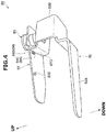
FIG. 4 is a perspective view of a yarn pressing member shown inFIG. 3 . -
FIG. 5 is another perspective view of the yarn pressing member shown inFIG. 3 . -
FIG. 6 is still another perspective view of the yarn pressing member shown inFIG. 3 . -
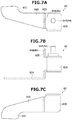
FIG. 7A is a plan view of a first pressing lever shown inFIG. 4 ,FIG. 7B is a front view of the first pressing lever shown inFIG. 4 , andFIG. 7C is a bottom view of the first pressing lever shown inFIG. 4 . -
FIG. 8A is a plan view of a second pressing lever shown inFIG. 4 , andFIG. 8B is a side view of the second pressing lever shown inFIG. 4 . -
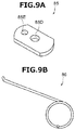
FIG. 9A is a perspective view of a plate-shaped member shown inFIG. 4 , andFIG. 9B is a perspective view of a coil spring shown inFIG. 4 . -
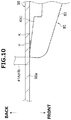
FIG. 10 is a diagram for explaining a case in which a first yarn end and a second yarn end are pressed by the yarn pressing member shown inFIG. 3 in cooperation with a contact surface, and is a horizontal sectional view showing a part of the yarn joining device in an enlarged manner. - Exemplary embodiments of the present invention are explained below with reference to the accompanying drawings. Identical elements or corresponding elements are indicated by the same reference symbols in the drawings and redundant explanation thereof is omitted.
- As shown in
FIG. 1 , anautomatic winder 1 includes a plurality of winder units (yarn winding device) 3 arranged side-by-side, amain control device 5, and adoffing device 7. Themain control device 5 is capable of communicating with each of the plurality of thewinder units 3. An operator of theautomatic winder 1 can collectively control the plurality of thewinder units 3 by appropriately operating themain control device 5. Eachwinder unit 3 unwinds a yarn Y from a yarn supplying bobbin SB and winds the yarn Y onto a winding bobbin WB while traversing the yarn Y to form a package P. When the package P in acertain winder unit 3 is fully wound (a state in which a specific amount of the yarn Y is wound), thedoffing device 7 travels to a position of thiswinder unit 3, removes the fully wound package P, and sets an empty winding bobbin WB in thewinder unit 3. - As shown in
FIG. 2 , thewinder unit 3 includes aunit controller 10, ayarn supplying device 12, and awinding section 14. Theunit controller 10 includes, for example, a CPU (Central Processing Unit) and a ROM (Read Only Memory). A computer program to control various components of thewinder unit 3 is stored in the ROM. The CPU executes the computer program stored in the ROM. - The
yarn supplying device 12 supports the yarn supplying bobbin SB, which has been set in a not-shown transport tray, at a certain position. Theyarn supplying device 12 unwinds draws the yarn Y from the yarn supplying bobbin SB and pulls the yarn Y from the yarn supplying bobbin SB. Theyarn supplying device 12 supplies the yarn Y to thewinding section 14. Theyarn supplying device 12 is not limited to a transport tray-type device and can be, for example, a magazine-type device. - The
winding section 14 includes acradle 16 and a winding drum 18. Thecradle 16 rotatably supports the winding bobbin WB (or package P) by pinching the winding bobbin WB. The winding drum 18 causes the package P to rotate while causing the yarn Y to traverse on the surface of the package P. The winding drum 18 is caused to drive rotatably by a not-shown drum driving motor. The package P is driven and rotated when an outer periphery of the package P is in contact with the rotating winding drum 18. A helical-shaped traverse groove is formed on the outer peripheral surface of the winding drum 18. The yarn Y unwound from the yarn supplying bobbin SB is wound onto the surface of the package P at a fixed width while being traversed via the traverse groove. Accordingly, the package P having a fixed winding width can be formed. - Each
winder unit 3 includes, sequentially from theyarn supplying device 12, a yarn unwinding assistingdevice 20, atension applying device 22, atension detecting device 24, ayarn joining device 26, and ayarn monitoring device 28 on a yarn path between theyarn supplying device 12 and thewinding section 14. A first catching and guidingdevice 30 and a second catching and guidingdevice 32 are arranged near theyarn joining device 26. - The yarn unwinding assisting
device 20 prevents excessive swinging by the centrifugal force of the yarn Y that is being unwound from the yarn supplying bobbin SB and appropriately unwinds the yarn Y from the yarn supplying bobbin SB. Thetension applying device 22 applies a predetermined tension to the running yarn Y. In the present embodiment, thetension applying device 22 is a gate-type device in which movable comb teeth are arranged against fixed comb teeth. - The
tension detecting device 24 detects the tension applied to the yarn Y running between theyarn supplying device 12 and thewinding section 14. When the yarn Y positioned between theyarn supplying device 12 and the windingsection 14 is disconnected due to some reason, theyarn joining device 26 joins the yarn Y on theyarn supplying device 12 side and the yarn Y on the windingsection 14 side. - The
yarn monitoring device 28 monitors the state of the yarn Y running on the yarn path, and detects presence of yarn defects based on the monitored information. The yarn defects include, for example, thickness defects of the yarn Y, foreign matter stuck to the yarn Y, and / or yarn breakage and the like. - The first catching and guiding
device 30 is pivotable from a waiting position on theyarn supplying device 12 side to a catching position on the windingsection 14 side. The first catching and guidingdevice 30 catches the yarn Y at the catching position and guides the yarn Y to theyarn joining device 26. The second catching and guidingdevice 32 is pivotable from a waiting position on theyarn supplying device 12 side to the catching position on the windingsection 14 side. The second catching and guidingdevice 32 catches the yarn Y at the catching position and guides the yarn Y to theyarn joining device 26. - Next, the
yarn joining device 26 will be explained in detail. -
FIG. 3 is a front view of theyarn joining device 26. In the following explanation, for the sake of convenience, the windingsection 14 side is referred to as an upper side, theyarn supplying device 12 side is referred to as a lower side, the running path of the yarn Y (yarn path) side with respect to theyarn joining device 26 is referred to as a front side, and an opposite side thereof is called a back side. Moreover, a yarn end of the yarn Y positioned on the windingsection 14 side is referred to as a first yarn end and a yarn end of the yarn Y positioned on theyarn supplying device 12 side is referred to as a second yarn end. - As shown in
FIG. 3 , theyarn joining device 26 includes a front plate (contact member) 90, an untwistingsection 40 that includes a firstuntwisting pipe member 41A and a seconduntwisting pipe member 41B, ayarn joining section 50 that performs yarn joining by injecting compressed air, a not-shown pair of yarn shifting levers capable of pivoting so as to pinch the untwistingsection 40, ayarn pressing member 80 that includes a firstpressing lever 82 and a secondpressing lever 83 capable of pivoting so as to pinch theyarn joining section 50, and anair guide 94. - The
front plate 90 is a plate-shaped member having a thickness direction thereof in the front-back direction. A front surface (contact surface) 90a of thefront plate 90 is flat and extends in a direction parallel to a yarn running direction. Theyarn joining section 50 is provided on thefront surface 90a of thefront plate 90. On thefront surface 90a of thefront plate 90, a first yarn end introducing port, which is an opening port of the firstuntwisting pipe member 41A, is provided above theyarn joining section 50, and a second yarn end introducing port, which is an opening port of the seconduntwisting pipe member 41B, is provided below theyarn joining section 50. - On the
front surface 90a of thefront plate 90, afirst guide member 45A is provided above the firstuntwisting pipe member 41A, and asecond guide member 45B is provided below the seconduntwisting pipe member 41B. Thefirst guide member 45A and thesecond guide member 45B are arranged so as to face each other with theyarn joining section 50 interposed therebetween. Thefirst guide member 45A guides the yarn Y guided by the first catching and guidingdevice 30 and thesecond guide member 45B guides the yarn Y guided by the second catching and guidingdevice 32. - The first
untwisting pipe member 41A untwists the first yarn end by the action of the compressed air. The seconduntwisting pipe member 41B untwists the second yarn end by the action of the compressed air. Theyarn joining section 50 twists and joins the first yarn end untwisted in the firstuntwisting pipe member 41A and the second yarn end untwisted in the seconduntwisting pipe member 41B by the action of the compressed air. When twisting the yarn ends in theyarn joining section 50, the first yarn end and the second yarn end are pulled, while being held by a not-shown clamp, from the firstuntwisting pipe member 41A and the seconduntwisting pipe member 41B by a not-shown yarn shifting lever and pressed near theyarn joining section 50 by the firstpressing lever 82 and the secondpressing lever 83. - The
yarn pressing member 80 is connected to, for example, a not-shown stepping motor and the like via a cam-link mechanism 95. Theyarn pressing member 80 is arranged movable so as to approach and separate from thefront surface 90a of thefront plate 90 by a driving force of a driving source. In other words, the firstpressing lever 82 and the secondpressing lever 83 of theyarn pressing member 80 are pivoted (rotated) by the driving force of the driving source such that tip end sides thereof approach and separate from thefront surface 90a of thefront plate 90. Theyarn pressing member 80 presses the first yarn end and the second yarn end in cooperation with thefront surface 90a when in contact with thefront surface 90a of thefront plate 90. The tip ends of the firstpressing lever 82 and the secondpressing lever 83 can be biased to the side that approaches thefront plate 90 by, for example, a not-shown helical torsion coil spring. Theair guide 94 is a member that guides the compressed air injected in theyarn joining section 50. Theair guide 94 is arranged so as to cover a part of opening ports positioned above and below a yarn joining chamber of theyarn joining section 50 to which the first yarn end and the second yarn end are guided. - In the
yarn joining device 26 having such a configuration, first, the not-shown first yarn shifting lever and the second yarn shifting lever, the firstpressing lever 82, and the secondpressing lever 83 pivot to thefront plate 90 side. Accordingly, the yarn Y on the upper side and the yarn Y on the lower side caught by the first catching and guidingdevice 30 and the second catching and guidingdevice 32 are pulled to the untwistingsection 40 side. Subsequently, the yarn Y on the upper side and the yarn Y on the lower side are held by the clamp and then cut in this state by a cutter. The first yarn end is fed to the inside of the firstuntwisting pipe member 41A and the second yarn end is fed to the inside of the seconduntwisting pipe member 41B. When the compressed air is injected in the firstuntwisting pipe member 41A and the seconduntwisting pipe member 41B, the first yarn end and the second yarn end are untwisted by the action of the compressed air. - Subsequently, the not-shown first yarn shifting lever and the second yarn shifting lever are further pivoted. Accordingly, the first yarn end and the second yarn end are pressed near the
yarn joining section 50 by the firstpressing lever 82 and the secondpressing lever 83 while being pulled from the firstuntwisting pipe member 41A and the seconduntwisting pipe member 41B. After this, injection of the compressed air is started in theyarn joining section 50, whereby the untwisted first yarn end and the second yarn end are twisted by the action of the compressed air. Then, the firstpressing lever 82 and the secondpressing lever 83 along with the not-shown first yarn shifting lever and the second yarn shifting lever are pivoted in the opposite direction. Accordingly, the yarn Y on the upper side and the yarn Y on the lower side held by the clamp are released. As a result, the connected yarn Y returns to the running path on the front side of theyarn joining device 26. Theyarn pressing member 80 and thefront plate 90 constitute a yarnpressing mechanism 100 that presses the first yarn end and the second yarn end in theyarn joining device 26. - Next, configuration of the
yarn pressing member 80 will be explained in detail. - As shown in one or more of
FIGS. 4 ,5 , and6 , theyarn pressing member 80 includes the firstpressing lever 82, the secondpressing lever 83, a linkingsection 84, a plate-shapedmember 85, and acoil spring 86. - As shown in one or more of
FIGS. 4 ,5 ,6 , and7A to 7C , the firstpressing lever 82 is a member that presses down the first yarn end. The firstpressing lever 82 is a plate-shaped lever. The firstpressing lever 82 includes a first levermain body 82A that is capable of contacting thefront plate 90, and a fixedportion 82B that is continuous with the base end side of the first levermain body 82A and to which the cam-link mechanism 95 is fixed (seeFIG. 3 ). The first levermain body 82A is plate shaped having the thickness direction thereof in the yarn running direction. Acontact portion 82C that is capable of contacting thefront plate 90 is provided on a tip end side of the first levermain body 82A. The fixedportion 82B is continuous with the front side of the base end side of the first levermain body 82A, bends at 90 degrees from the first levermain body 82A, then extends upward, again bends at 90 degrees, and then extends to the back side. - As shown in one or more of
FIGS. 4 ,5 ,6 , and8A and 8B , the secondpressing lever 83 is a member that presses down the second yarn end. The secondpressing lever 83 is parallel to the firstpressing lever 82 with a predetermined distance therebetween along the yarn running direction. The secondpressing lever 83 is plate shaped having the thickness direction thereof in the yarn running direction. Acontact portion 83C that is capable of contacting thefront plate 90 is provided at a tip end side of the secondpressing lever 83. - The linking
section 84 movably links the secondpressing lever 83 with the firstpressing lever 82 such that the secondpressing lever 83 can approach and separate from thefront surface 90a of thefront plate 90. The linkingsection 84 includes ashaft portion 84A, a protrudingportion 84B, and ahole portion 84C. - The
shaft portion 84A is provided on the firstpressing lever 82 and pivotably supports the secondpressing lever 83 with respect to the firstpressing lever 82 such that the secondpressing lever 83 can approach and separate from thefront surface 90a. Theshaft portion 84A is a cross-sectional circular shaft body that is arranged orthogonally on an upper surface of the fixedportion 82B of the firstpressing lever 82 and has a shaft direction in the yarn running direction. A not-shown hole is formed inside theshaft portion 84A along the shaft direction of theshaft portion 84A. Theshaft portion 84A is inserted into ahole 83D formed on a base end side of the secondpressing lever 83 so as to protrude through thehole 83D. - The protruding
portion 84B is provided on the firstpressing lever 82. The protrudingportion 84B is arranged on an upper surface of anupright plate portion 82D that is continuous with the upper surface of the fixedportion 82B of the firstpressing lever 82, bends at 90 degrees, and then extends upward so as to protrude upward in a cross-sectional rectangular shape. - The
hole portion 84C is a circular hole formed on the secondpressing lever 83 through which the protrudingportion 84B is inserted. In an example shown in the figure, thehole portion 84C is provided on a side of thehole 83D in the secondpressing lever 83. When the protrudingportion 84B is inserted in thehole portion 84C, a certain gap is formed between an internal surface of thehole portion 84C and the protrudingportion 84B. In other words, the protrudingportion 84B is movably inserted in thehole portion 84C so as to move by a certain amount to approach and separate from thefront surface 90a of thefront plate 90. - The first
pressing lever 82 and the secondpressing lever 83 are linked bysuch linking section 84. Moreover, the tip end side of the secondpressing lever 83 is pivotable by a certain amount (within a scope in which the protrudingportion 84B can move inside thehole portion 84C) around the base end side thereof with respect to the firstpressing lever 82. - As shown in
FIGS. 6 and9A , the plate-shapedmember 85 is a plate-shaped piece member having the thickness direction thereof in the yarn running direction. Ahole 85D through which a screw N is inserted is formed in the plate-shapedmember 85. The plate-shapedmember 85 is fastened to an upper end portion of theshaft portion 84A and is thereby integrated with the firstpressing lever 82. - As shown in
FIGS. 6 and9B , thecoil spring 86 is an elastic member (biasing member) that biases the secondpressing lever 83 so as to approach thefront surface 90a. Thecoil spring 86 is mounted between the secondpressing lever 83 and the plate-shapedmember 85 around the periphery of theshaft portion 84A. An end of thecoil spring 86 is engaged with anengagement hole 83E formed in the secondpressing lever 83. Other end of thecoil spring 86 is engaged with anengagement hole 85E formed on the plate-shapedmember 85. Withsuch coil spring 86, the secondpressing lever 83 is biased with respect to the firstpressing lever 82 such that the tip end side of the secondpressing lever 83 is biased toward thefront surface 90a. - As shown in
FIGS. 3 to 6 , theyarn pressing member 80 is driven via the cam-link mechanism 95 by a not-shown driving source such as a stepping motor, and the firstpressing lever 82 and the secondpressing lever 83 are pivoted integrally such that thecontact portion 82C and thecontact portion 83C on the tip end sides of the firstpressing lever 82 and the secondpressing lever 83 approach thefront surface 90a of thefront plate 90. Thecontact portion 82C of the firstpressing lever 82 and thecontact portion 83C of the secondpressing lever 83 contact thefront surface 90a, and the first yarn end and the second yarn end are pinched between thecontact portions front surface 90a. The first yarn end and the second yarn end are regulated by a wedge-shaped small gaps K (seeFIG. 10 ). Accordingly, the first yarn end and the second yarn end are pressed down by theyarn pressing member 80 in cooperation with thefront surface 90a. In this state, even when thecontact portion 82C of the firstpressing lever 82 and thecontact portion 83C of the secondpressing lever 83 cannot contact thefront surface 90a at the same time, because the firstpressing lever 82 and the secondpressing lever 83 are separated from each other and are connected elastically, the firstpressing lever 82 and the secondpressing lever 83 contact thefront surface 90a in a like manner. - In the yarn
pressing mechanism 100 explained above, when the first yarn end and the second yarn end are pressed by theyarn pressing member 80 in cooperation with thefront surface 90a, the firstpressing lever 82 and the secondpressing lever 83 can be caused to contact thefront surface 90a in the like manner and the first yarn end and the second yarn end can be pressed in the like manner. Consequently, a proper joint of the yarn Y can be formed and the shape of the joint of the yarn Y can be improved. Also, the strength of the joint of the yarn Y can be improved. - The yarn
pressing mechanism 100 includes thecoil spring 86, which is an elastic member, as a biasing member. In such a configuration, by using the elastic force of thecoil spring 86, which is an elastic member, the secondpressing lever 83 can be biased toward thefront surface 90a. - In the yarn
pressing mechanism 100, the firstpressing lever 82 and the secondpressing lever 83 regulates the first yarn end and the second yarn end with the wedge-shaped gap K. Accordingly, instead of firmly pressing the first yarn end and the second yarn end in cooperation with thefront surface 90a, the firstpressing lever 82 and the secondpressing lever 83 can regulate the first yarn end and the second yarn end with the wedge-shaped gap K. As a result, the yarn Y can be prevented from escaping from the working range of theyarn joining device 26 due to self contracting force, and furthermore, when it is necessary to guide (move) the yarn Y for yarn joining, the yarn Y can be caused to move by applying a strong force to a certain extent to the yarn Y, without releasing the contact by the firstpressing lever 82 and the secondpressing lever 83. Accordingly, because a driving frequency of the firstpressing lever 82 and the secondpressing lever 83 can be set to a minimum necessary frequency, an operation frequency of the firstpressing lever 82 and the secondpressing lever 83 is reduced, thus suppressing the fatigue deterioration, and furthermore, by suppressing the number of movements of members involved in the yarn joining, improvement in work efficiency can be expected. - In the yarn
pressing mechanism 100, the linkingsection 84 includes theshaft portion 84A, the protrudingportion 84B, and thehole portion 84C. With such a configuration, the linkingsection 84 that links the secondpressing lever 83 to the firstpressing lever 82 so as to be movable can be realized with a simple configuration, without using another stopper member and the like. - In the yarn
pressing mechanism 100, one end of thecoil spring 86 is engaged with the secondpressing lever 83 and the other end thereof is engaged with the plate-shapedmember 85. With such a configuration, a biasing member that biases the secondpressing lever 83 toward thefront surface 90a can be concretely realized. - The
yarn joining device 26 includes the yarnpressing mechanism 100. Therefore, theyarn joining device 26 can achieve the effects and advantages explained above such as improvement in the shape of the joint of the yarn Y. - The
winder unit 3 includes theyarn joining device 26. Therefore, thewinder unit 3 can achieve the effects and advantages explained above such as improvement in the shape of the joint of the yarn Y. - Embodiments of the present invention are explained above; however, an aspect of the present invention is not limited thereto.
- In the embodiments explained above, the yarn
pressing mechanism 100 is applied to theyarn joining device 26 of thewinder unit 3; however, the yarnpressing mechanism 100 can be applied to the yarn joining device of a winding unit of a spinning machine. Alternatively, the yarnpressing mechanism 100 can be applied to a yarn joining machine of a work carrier that moves among a plurality of the winding units. In the embodiments explained above, a magnet can be used as a biasing member. In a configuration in which the magnet is used as a biasing member, the secondpressing lever 83 can be biased toward thefront surface 90a by using the magnetic force. - A yarn pressing mechanism used in a yarn joining device to press a first yarn end and a second yarn end when joining the first yarn end and the second yarn end by the action of compressed air according to one aspect of the present invention includes a contact member having a contact surface that extends horizontally in a yarn running direction; and a yarn pressing member that is arranged movably so as to approach and separate from the contact surface, and presses the first yarn end and the second yarn end in cooperation with the contact surface by contacting the contact surface. The yarn pressing member includes a first pressing lever that presses the first yarn end in cooperation with the contact surface; a second pressing lever that presses the second yarn end in cooperation with the contact surface; a linking section that links the second pressing lever to the first pressing lever so as to be movable; and a biasing member that biases the second pressing lever with respect to the first pressing lever such that the second pressing lever is biased toward the contact surface. Moreover, the second pressing lever is biased by the biasing member such that the second pressing lever is arranged closer to the contact surface than the first pressing lever.
- In the yarn pressing mechanism of such a yarn joining device, the second pressing lever is linked movably with respect to the first pressing lever, and the second pressing lever is biased toward the contact portion. Accordingly, both the first pressing lever and the second pressing lever can be caused to contact the front surface in the like manner and both the first yarn end and the second yarn end can be pressed in the like manner in cooperation with the contact surface. Consequently, an appropriate yarn joint can be formed, and the shape of the yarn joint can be improved.
- In the above yarn pressing mechanism of the yarn joining device according to the present invention, the biasing member can be an elastic member. In such a configuration, the second pressing lever can be biased so as to approach the contact surface by using the elastic force of the elastic member.
- In the above yarn pressing mechanism of the yarn joining device according to the present invention, the elastic member can be a coil spring. With such a configuration, the second pressing lever can be biased so as to approach the contact surface by using the elastic force of the coil spring.
- In the above yarn pressing mechanism of the yarn joining device according to the present invention, the biasing member can be a magnet. With such a configuration, the second pressing lever can be biased so as to approach the contact surface by using the magnetic force.
- In the above yarn pressing mechanism of the yarn joining device according to the present invention, the first pressing lever can regulate the first yarn end by using a wedge-shaped gap formed between the first pressing lever and the contact surface when a tip end side of the first pressing lever contacts the contact surface, and the second pressing lever can regulate the second yarn end by using a wedge-shaped gap formed between the second pressing lever and the contact surface when a tip end side of the second pressing lever contacts the contact surface. With such a configuration, instead of firmly pressing the first yarn end and the second yarn end in cooperation with the contact portion, the first yarn end and the second yarn end can be regulated by using the wedge-shaped gap. As a result, the yarn can be prevented from escaping from the working range of the yarn joining device due to own contracting force, and furthermore, when it is necessary to guide (move) the yarn for yarn joining, the yarn can be caused to move by applying a strong force to a certain extent to the yarn, without releasing the contact by the first pressing lever and the second pressing lever. Accordingly, because the driving frequency of the first pressing lever and the second pressing lever can be set to a minimum necessary frequency, fatigue deterioration of the first pressing lever and the second pressing lever can be suppressed, and by suppressing the number of movements of members involved in the yarn joining, improvement in work efficiency can be expected.
- In the above yarn pressing mechanism of the yarn joining device according to the present invention, the linking section includes a shaft portion that pivotably supports the second pressing lever with respect to the first pressing lever such that the second pressing lever can approach and separate from the contact surface; a protruding portion formed in the first pressing lever; and a hole portion that is formed in the second pressing lever and through which the protruding portion is inserted so as to move by a certain amount to approach and separate from the contact surface. With such a configuration, the linking portion that links the second pressing lever to the first pressing lever so as to be movable can be realized with a simple configuration, without using another stopper member and the like.
- In the above yarn pressing mechanism of the yarn joining device according to the present invention, the biasing member can be a coil spring, and one end of the coil spring is engaged with the second pressing lever and other end of the coil spring is engaged with a plate-shaped member that is arranged fixedly on the shaft portion. With such a configuration, a biasing member that biases the second pressing lever so as to approach the contact portion can be concretely realized.
- A yarn joining device according to another aspect of the present invention includes the above yarn pressing mechanism of the yarn joining device. In such a yarn joining device, effects and advantages explained above such as improvement in the shape of the joint of the yarn can be achieved.
- A yarn winding device according to still another aspect of the present invention includes the above yarn joining device and further includes a yarn supplying device that supports a yarn supplying bobbin at a predetermined position; a winding section; an untwisting assisting device; a tension applying device; and a yarn monitoring device. In such a winding device, effects and advantages explained above such as improvement in the shape of the joint of the yarn can be achieved.
- According to the present invention, the yarn pressing mechanism of the yarn joining device capable of improving the shape of the yarn joint, the yarn joining device, and the yarn winding device can be provided.
- In the above explanation, the meaning of "a plurality of" also includes "a predetermined number of".
- Although the invention has been explained with respect to specific embodiments for a complete and clear disclosure, the appended claims are not to be thus limited but are to be construed as embodying all modifications and alternative constructions that may occur to one skilled in the art that fairly fall within the scope of the claims.
Claims (10)
- A yarn pressing mechanism (100)used in a yarn joining device (26) to press a first yarn end and a second yarn end when joining the first yarn end and the second yarn end by the action of compressed air, comprising:a contact member (90) having a contact surface (90a) that extends horizontally in a yarn running direction: anda yarn pressing member (80) that is arranged movably so as to approach and separate from the contact surface (90a), and presses the first yarn end and the second yarn end in cooperation with the contact surface (90a) by contacting the contact surface (90a), wherein the yarn pressing member (80) includesa first pressing lever (82) that presses the first yarn end in cooperation with the contact surface (90a);a second pressing lever (83) that presses the second yarn end in cooperation with the contact surface (90a);a linking section (84) that links the second pressing lever (83) to the first pressing lever (82) so as to be movable; anda biasing member (86) that biases the second pressing lever (83) with respect to the first pressing lever (82) such that the second pressing lever (83) is biased toward the contact surface (90a) side.
- The yarn pressing mechanism (100) of the yarn joining device (26) as claimed in Claim 1, wherein the second pressing lever (83) is biased by the biasing member (86) such that the second pressing lever (83) is arranged closer to the contact surface (90a) than the first pressing lever (82).
- The yarn pressing mechanism (100) of the yarn joining device (26) as claimed in Claim 2, wherein the biasing member (86) is an elastic member.
- The yarn pressing mechanism (100) of the yarn joining device (26) as claimed in Claim 3, wherein the elastic member (86) is a coil spring (86).
- The yarn pressing mechanism (100) of the yarn joining device (26) as claimed in Claim 2, wherein the biasing member (86) is a magnet.
- The yarn pressing mechanism (100) of the yarn joining device (26) as claimed in any one of Claims 1 to 5, wherein
the first pressing lever (82) regulates the first yarn end by using a wedge-shaped gap formed between the first pressing lever (82) and the contact surface (90a) when a tip end side of the first pressing lever (82) contacts the contact surface (90a), and
the second pressing lever (83) regulates the second yarn end by using a wedge-shaped gap formed between the second pressing lever (83) and the contact surface (90a) when a tip end side of the second pressing lever (83) contacts the contact surface (90a). - The yarn pressing mechanism (100) of the yarn joining device (26) as claimed in any one of Claims 1 to 6, wherein the linking section (84) includes
a shaft portion (84A) formed in the first pressing lever (82) and that pivotably supports the second pressing lever (83) with respect to the first pressing lever (82) such that the second pressing lever (83) can approach and separate from the contact surface (90a);
a protruding portion (84B) formed in the first pressing lever (82); and
a hole portion (84C) that is formed in the second pressing lever (83) and through which the protruding portion (84B) is inserted so as to move by a certain amount to approach and separate from the contact surface (90a). - The yarn pressing mechanism (100) of the yarn joining device (26) as claimed in Claim 7, wherein the biasing member (86) is a coil spring, and one end of the coil spring (86) is engaged with the second pressing lever (83) and other end of the coil spring (86) is engaged with a plate-shaped member (85) that is arranged fixedly on the shaft portion (84A).
- A yarn joining device (26) that includes the yarn pressing mechanism (100) as claimed in any one of Claims 1 to 8.
- A yarn winding device (3) that includes the yarn joining device (26) as claimed in Claim 9, and comprising:a yarn supplying device (12) that supports a yarn supplying bobbin (SB) at a predetermined position;a winding section (14);an untwisting assisting device (20);a tension applying device (22); anda yarn monitoring device (28).
Applications Claiming Priority (1)
| Application Number | Priority Date | Filing Date | Title |
|---|---|---|---|
| JP2019220651A JP2021088450A (en) | 2019-12-05 | 2019-12-05 | Thread pressing structure of thread piecing device, thread piecing device and winding device |
Publications (2)
| Publication Number | Publication Date |
|---|---|
| EP3831755A1 true EP3831755A1 (en) | 2021-06-09 |
| EP3831755B1 EP3831755B1 (en) | 2023-05-31 |
Family
ID=73043162
Family Applications (1)
| Application Number | Title | Priority Date | Filing Date |
|---|---|---|---|
| EP20205150.4A Active EP3831755B1 (en) | 2019-12-05 | 2020-11-02 | Yarn pressing mechanism of yarn joining device, yarn joining device, and yarn winding device |
Country Status (3)
| Country | Link |
|---|---|
| EP (1) | EP3831755B1 (en) |
| JP (1) | JP2021088450A (en) |
| CN (1) | CN112919257B (en) |
Citations (4)
| Publication number | Priority date | Publication date | Assignee | Title |
|---|---|---|---|---|
| US4416110A (en) * | 1981-03-23 | 1983-11-22 | Murata Kikai Kabushiki Kaisha | Splicing apparatus for spun yarns |
| DE19538432A1 (en) * | 1995-10-16 | 1997-04-17 | Akzo Nobel Nv | Splicing appts for multifilament yarns |
| DE102016000922A1 (en) * | 2015-02-24 | 2016-08-25 | Murata Machinery, Ltd. | Garnspulvorrichtung and textile machine |
| JP6478687B2 (en) | 2014-02-15 | 2019-03-06 | ザウラー ジャーマニー ゲゼルシャフト ミット ベシュレンクテル ハフツング ウント コンパニー コマンディートゲゼルシャフトSaurer Germany GmbH & Co. KG | Method, apparatus and computer program for untwisting yarn end for splicer |
Family Cites Families (2)
| Publication number | Priority date | Publication date | Assignee | Title |
|---|---|---|---|---|
| JP2015174757A (en) * | 2014-03-18 | 2015-10-05 | 村田機械株式会社 | Thread piecing device, take-up unit, and textile machine |
| JP2016102005A (en) * | 2014-11-28 | 2016-06-02 | 村田機械株式会社 | Yarn splicing device, yarn winding machine and yarn splicing method |
-
2019
- 2019-12-05 JP JP2019220651A patent/JP2021088450A/en active Pending
-
2020
- 2020-11-02 EP EP20205150.4A patent/EP3831755B1/en active Active
- 2020-11-26 CN CN202011344505.1A patent/CN112919257B/en active Active
Patent Citations (4)
| Publication number | Priority date | Publication date | Assignee | Title |
|---|---|---|---|---|
| US4416110A (en) * | 1981-03-23 | 1983-11-22 | Murata Kikai Kabushiki Kaisha | Splicing apparatus for spun yarns |
| DE19538432A1 (en) * | 1995-10-16 | 1997-04-17 | Akzo Nobel Nv | Splicing appts for multifilament yarns |
| JP6478687B2 (en) | 2014-02-15 | 2019-03-06 | ザウラー ジャーマニー ゲゼルシャフト ミット ベシュレンクテル ハフツング ウント コンパニー コマンディートゲゼルシャフトSaurer Germany GmbH & Co. KG | Method, apparatus and computer program for untwisting yarn end for splicer |
| DE102016000922A1 (en) * | 2015-02-24 | 2016-08-25 | Murata Machinery, Ltd. | Garnspulvorrichtung and textile machine |
Also Published As
| Publication number | Publication date |
|---|---|
| CN112919257A (en) | 2021-06-08 |
| JP2021088450A (en) | 2021-06-10 |
| EP3831755B1 (en) | 2023-05-31 |
| CN112919257B (en) | 2025-05-06 |
Similar Documents
| Publication | Publication Date | Title |
|---|---|---|
| JP4110415B2 (en) | Yarn splicer and handy splicer | |
| JP2016155648A (en) | Piecing unit and yarn winding device | |
| JP2018030722A (en) | Thread splicing device for work unit of textile machine for manufacturing twill winding package | |
| EP3858774A1 (en) | Yarn joining device, winding unit, and yarn winding machine | |
| CN106698096B (en) | Yarn joining mechanism, yarn winding device, and yarn joining method | |
| JP2013067464A (en) | Yarn piecing device and yarn winding device | |
| JP2012001349A (en) | Yarn splicing device, and yarn winding device having the same | |
| EP2573031A2 (en) | Yarn processing device and yarn winding device | |
| EP3831755B1 (en) | Yarn pressing mechanism of yarn joining device, yarn joining device, and yarn winding device | |
| CN204569014U (en) | Piecing devices, winder unit and fibre machinery | |
| EP3025996B1 (en) | Yarn winding machine with a yarn joining device, and yarn joining method | |
| CN106904492B (en) | Guide plate, yarn splicing device and station operation method | |
| EP4071097B1 (en) | Yarn splicing nozzle and winding device | |
| EP3831756B1 (en) | Yarn joining device, yarn joining nozzle structure, and winding device | |
| EP3466856A1 (en) | Yarn joining nozzle, yarn joining device, yarn winding device, and yarn joining method | |
| CN111470382B (en) | Yarn joining device and yarn winding device | |
| CN113825714B (en) | Line body winding device and line body winding method | |
| CN115303879A (en) | Connecting part and yarn hanging method | |
| IT8349503A1 (en) | METHOD AND APPARATUS FOR JOINING TEXTILE THREADS. | |
| JP2014234311A (en) | Yarn splicing device, winding unit, textile machine and yarn splicing method | |
| JP2022113421A (en) | Yarn winding device | |
| JP2015161032A (en) | Yarn storage device, yarn winding unit therewith and yarn winder therewith | |
| JPH0545698B2 (en) | ||
| JP2019023120A (en) | Yarn splicing device and yarn winding device | |
| JP2019064803A (en) | Yarn splicing device, yarn winding device, and yarn splicing method |
Legal Events
| Date | Code | Title | Description |
|---|---|---|---|
| PUAI | Public reference made under article 153(3) epc to a published international application that has entered the european phase |
Free format text: ORIGINAL CODE: 0009012 |
|
| STAA | Information on the status of an ep patent application or granted ep patent |
Free format text: STATUS: THE APPLICATION HAS BEEN PUBLISHED |
|
| AK | Designated contracting states |
Kind code of ref document: A1 Designated state(s): AL AT BE BG CH CY CZ DE DK EE ES FI FR GB GR HR HU IE IS IT LI LT LU LV MC MK MT NL NO PL PT RO RS SE SI SK SM TR |
|
| STAA | Information on the status of an ep patent application or granted ep patent |
Free format text: STATUS: REQUEST FOR EXAMINATION WAS MADE |
|
| 17P | Request for examination filed |
Effective date: 20210726 |
|
| RBV | Designated contracting states (corrected) |
Designated state(s): AL AT BE BG CH CY CZ DE DK EE ES FI FR GB GR HR HU IE IS IT LI LT LU LV MC MK MT NL NO PL PT RO RS SE SI SK SM TR |
|
| GRAP | Despatch of communication of intention to grant a patent |
Free format text: ORIGINAL CODE: EPIDOSNIGR1 |
|
| STAA | Information on the status of an ep patent application or granted ep patent |
Free format text: STATUS: GRANT OF PATENT IS INTENDED |
|
| INTG | Intention to grant announced |
Effective date: 20221220 |
|
| GRAS | Grant fee paid |
Free format text: ORIGINAL CODE: EPIDOSNIGR3 |
|
| GRAA | (expected) grant |
Free format text: ORIGINAL CODE: 0009210 |
|
| STAA | Information on the status of an ep patent application or granted ep patent |
Free format text: STATUS: THE PATENT HAS BEEN GRANTED |
|
| AK | Designated contracting states |
Kind code of ref document: B1 Designated state(s): AL AT BE BG CH CY CZ DE DK EE ES FI FR GB GR HR HU IE IS IT LI LT LU LV MC MK MT NL NO PL PT RO RS SE SI SK SM TR |
|
| REG | Reference to a national code |
Ref country code: GB Ref legal event code: FG4D Ref country code: CH Ref legal event code: EP |
|
| REG | Reference to a national code |
Ref country code: AT Ref legal event code: REF Ref document number: 1570829 Country of ref document: AT Kind code of ref document: T Effective date: 20230615 Ref country code: DE Ref legal event code: R096 Ref document number: 602020011289 Country of ref document: DE |
|
| REG | Reference to a national code |
Ref country code: IE Ref legal event code: FG4D |
|
| REG | Reference to a national code |
Ref country code: LT Ref legal event code: MG9D |
|
| REG | Reference to a national code |
Ref country code: NL Ref legal event code: MP Effective date: 20230531 |
|
| REG | Reference to a national code |
Ref country code: AT Ref legal event code: MK05 Ref document number: 1570829 Country of ref document: AT Kind code of ref document: T Effective date: 20230531 |
|
| PG25 | Lapsed in a contracting state [announced via postgrant information from national office to epo] |
Ref country code: SE Free format text: LAPSE BECAUSE OF FAILURE TO SUBMIT A TRANSLATION OF THE DESCRIPTION OR TO PAY THE FEE WITHIN THE PRESCRIBED TIME-LIMIT Effective date: 20230531 Ref country code: NO Free format text: LAPSE BECAUSE OF FAILURE TO SUBMIT A TRANSLATION OF THE DESCRIPTION OR TO PAY THE FEE WITHIN THE PRESCRIBED TIME-LIMIT Effective date: 20230831 Ref country code: ES Free format text: LAPSE BECAUSE OF FAILURE TO SUBMIT A TRANSLATION OF THE DESCRIPTION OR TO PAY THE FEE WITHIN THE PRESCRIBED TIME-LIMIT Effective date: 20230531 Ref country code: AT Free format text: LAPSE BECAUSE OF FAILURE TO SUBMIT A TRANSLATION OF THE DESCRIPTION OR TO PAY THE FEE WITHIN THE PRESCRIBED TIME-LIMIT Effective date: 20230531 |
|
| PG25 | Lapsed in a contracting state [announced via postgrant information from national office to epo] |
Ref country code: RS Free format text: LAPSE BECAUSE OF FAILURE TO SUBMIT A TRANSLATION OF THE DESCRIPTION OR TO PAY THE FEE WITHIN THE PRESCRIBED TIME-LIMIT Effective date: 20230531 Ref country code: PL Free format text: LAPSE BECAUSE OF FAILURE TO SUBMIT A TRANSLATION OF THE DESCRIPTION OR TO PAY THE FEE WITHIN THE PRESCRIBED TIME-LIMIT Effective date: 20230531 Ref country code: NL Free format text: LAPSE BECAUSE OF FAILURE TO SUBMIT A TRANSLATION OF THE DESCRIPTION OR TO PAY THE FEE WITHIN THE PRESCRIBED TIME-LIMIT Effective date: 20230531 Ref country code: LV Free format text: LAPSE BECAUSE OF FAILURE TO SUBMIT A TRANSLATION OF THE DESCRIPTION OR TO PAY THE FEE WITHIN THE PRESCRIBED TIME-LIMIT Effective date: 20230531 Ref country code: LT Free format text: LAPSE BECAUSE OF FAILURE TO SUBMIT A TRANSLATION OF THE DESCRIPTION OR TO PAY THE FEE WITHIN THE PRESCRIBED TIME-LIMIT Effective date: 20230531 Ref country code: IS Free format text: LAPSE BECAUSE OF FAILURE TO SUBMIT A TRANSLATION OF THE DESCRIPTION OR TO PAY THE FEE WITHIN THE PRESCRIBED TIME-LIMIT Effective date: 20230930 Ref country code: HR Free format text: LAPSE BECAUSE OF FAILURE TO SUBMIT A TRANSLATION OF THE DESCRIPTION OR TO PAY THE FEE WITHIN THE PRESCRIBED TIME-LIMIT Effective date: 20230531 Ref country code: GR Free format text: LAPSE BECAUSE OF FAILURE TO SUBMIT A TRANSLATION OF THE DESCRIPTION OR TO PAY THE FEE WITHIN THE PRESCRIBED TIME-LIMIT Effective date: 20230901 |
|
| PG25 | Lapsed in a contracting state [announced via postgrant information from national office to epo] |
Ref country code: FI Free format text: LAPSE BECAUSE OF FAILURE TO SUBMIT A TRANSLATION OF THE DESCRIPTION OR TO PAY THE FEE WITHIN THE PRESCRIBED TIME-LIMIT Effective date: 20230531 |
|
| PG25 | Lapsed in a contracting state [announced via postgrant information from national office to epo] |
Ref country code: SK Free format text: LAPSE BECAUSE OF FAILURE TO SUBMIT A TRANSLATION OF THE DESCRIPTION OR TO PAY THE FEE WITHIN THE PRESCRIBED TIME-LIMIT Effective date: 20230531 |
|
| PG25 | Lapsed in a contracting state [announced via postgrant information from national office to epo] |
Ref country code: SM Free format text: LAPSE BECAUSE OF FAILURE TO SUBMIT A TRANSLATION OF THE DESCRIPTION OR TO PAY THE FEE WITHIN THE PRESCRIBED TIME-LIMIT Effective date: 20230531 Ref country code: SK Free format text: LAPSE BECAUSE OF FAILURE TO SUBMIT A TRANSLATION OF THE DESCRIPTION OR TO PAY THE FEE WITHIN THE PRESCRIBED TIME-LIMIT Effective date: 20230531 Ref country code: RO Free format text: LAPSE BECAUSE OF FAILURE TO SUBMIT A TRANSLATION OF THE DESCRIPTION OR TO PAY THE FEE WITHIN THE PRESCRIBED TIME-LIMIT Effective date: 20230531 Ref country code: PT Free format text: LAPSE BECAUSE OF FAILURE TO SUBMIT A TRANSLATION OF THE DESCRIPTION OR TO PAY THE FEE WITHIN THE PRESCRIBED TIME-LIMIT Effective date: 20231002 Ref country code: EE Free format text: LAPSE BECAUSE OF FAILURE TO SUBMIT A TRANSLATION OF THE DESCRIPTION OR TO PAY THE FEE WITHIN THE PRESCRIBED TIME-LIMIT Effective date: 20230531 Ref country code: DK Free format text: LAPSE BECAUSE OF FAILURE TO SUBMIT A TRANSLATION OF THE DESCRIPTION OR TO PAY THE FEE WITHIN THE PRESCRIBED TIME-LIMIT Effective date: 20230531 Ref country code: CZ Free format text: LAPSE BECAUSE OF FAILURE TO SUBMIT A TRANSLATION OF THE DESCRIPTION OR TO PAY THE FEE WITHIN THE PRESCRIBED TIME-LIMIT Effective date: 20230531 |
|
| PGFP | Annual fee paid to national office [announced via postgrant information from national office to epo] |
Ref country code: TR Payment date: 20231020 Year of fee payment: 4 |
|
| REG | Reference to a national code |
Ref country code: DE Ref legal event code: R097 Ref document number: 602020011289 Country of ref document: DE |
|
| PLBE | No opposition filed within time limit |
Free format text: ORIGINAL CODE: 0009261 |
|
| STAA | Information on the status of an ep patent application or granted ep patent |
Free format text: STATUS: NO OPPOSITION FILED WITHIN TIME LIMIT |
|
| PG25 | Lapsed in a contracting state [announced via postgrant information from national office to epo] |
Ref country code: SI Free format text: LAPSE BECAUSE OF FAILURE TO SUBMIT A TRANSLATION OF THE DESCRIPTION OR TO PAY THE FEE WITHIN THE PRESCRIBED TIME-LIMIT Effective date: 20230531 |
|
| 26N | No opposition filed |
Effective date: 20240301 |
|
| PG25 | Lapsed in a contracting state [announced via postgrant information from national office to epo] |
Ref country code: SI Free format text: LAPSE BECAUSE OF FAILURE TO SUBMIT A TRANSLATION OF THE DESCRIPTION OR TO PAY THE FEE WITHIN THE PRESCRIBED TIME-LIMIT Effective date: 20230531 |
|
| REG | Reference to a national code |
Ref country code: CH Ref legal event code: PL |
|
| PG25 | Lapsed in a contracting state [announced via postgrant information from national office to epo] |
Ref country code: MC Free format text: LAPSE BECAUSE OF FAILURE TO SUBMIT A TRANSLATION OF THE DESCRIPTION OR TO PAY THE FEE WITHIN THE PRESCRIBED TIME-LIMIT Effective date: 20230531 |
|
| PG25 | Lapsed in a contracting state [announced via postgrant information from national office to epo] |
Ref country code: LU Free format text: LAPSE BECAUSE OF NON-PAYMENT OF DUE FEES Effective date: 20231102 |
|
| PG25 | Lapsed in a contracting state [announced via postgrant information from national office to epo] |
Ref country code: CH Free format text: LAPSE BECAUSE OF NON-PAYMENT OF DUE FEES Effective date: 20231130 |
|
| PG25 | Lapsed in a contracting state [announced via postgrant information from national office to epo] |
Ref country code: MC Free format text: LAPSE BECAUSE OF FAILURE TO SUBMIT A TRANSLATION OF THE DESCRIPTION OR TO PAY THE FEE WITHIN THE PRESCRIBED TIME-LIMIT Effective date: 20230531 Ref country code: LU Free format text: LAPSE BECAUSE OF NON-PAYMENT OF DUE FEES Effective date: 20231102 Ref country code: CH Free format text: LAPSE BECAUSE OF NON-PAYMENT OF DUE FEES Effective date: 20231130 |
|
| REG | Reference to a national code |
Ref country code: BE Ref legal event code: MM Effective date: 20231130 |
|
| REG | Reference to a national code |
Ref country code: IE Ref legal event code: MM4A |
|
| PG25 | Lapsed in a contracting state [announced via postgrant information from national office to epo] |
Ref country code: IE Free format text: LAPSE BECAUSE OF NON-PAYMENT OF DUE FEES Effective date: 20231102 |
|
| PG25 | Lapsed in a contracting state [announced via postgrant information from national office to epo] |
Ref country code: BE Free format text: LAPSE BECAUSE OF NON-PAYMENT OF DUE FEES Effective date: 20231130 |
|
| PG25 | Lapsed in a contracting state [announced via postgrant information from national office to epo] |
Ref country code: FR Free format text: LAPSE BECAUSE OF NON-PAYMENT OF DUE FEES Effective date: 20231130 |
|
| PG25 | Lapsed in a contracting state [announced via postgrant information from national office to epo] |
Ref country code: IE Free format text: LAPSE BECAUSE OF NON-PAYMENT OF DUE FEES Effective date: 20231102 Ref country code: FR Free format text: LAPSE BECAUSE OF NON-PAYMENT OF DUE FEES Effective date: 20231130 Ref country code: BE Free format text: LAPSE BECAUSE OF NON-PAYMENT OF DUE FEES Effective date: 20231130 |
|
| PG25 | Lapsed in a contracting state [announced via postgrant information from national office to epo] |
Ref country code: BG Free format text: LAPSE BECAUSE OF FAILURE TO SUBMIT A TRANSLATION OF THE DESCRIPTION OR TO PAY THE FEE WITHIN THE PRESCRIBED TIME-LIMIT Effective date: 20230531 |
|
| PG25 | Lapsed in a contracting state [announced via postgrant information from national office to epo] |
Ref country code: BG Free format text: LAPSE BECAUSE OF FAILURE TO SUBMIT A TRANSLATION OF THE DESCRIPTION OR TO PAY THE FEE WITHIN THE PRESCRIBED TIME-LIMIT Effective date: 20230531 |
|
| GBPC | Gb: european patent ceased through non-payment of renewal fee |
Effective date: 20241102 |
|
| PG25 | Lapsed in a contracting state [announced via postgrant information from national office to epo] |
Ref country code: CY Free format text: LAPSE BECAUSE OF FAILURE TO SUBMIT A TRANSLATION OF THE DESCRIPTION OR TO PAY THE FEE WITHIN THE PRESCRIBED TIME-LIMIT; INVALID AB INITIO Effective date: 20201102 |
|
| PG25 | Lapsed in a contracting state [announced via postgrant information from national office to epo] |
Ref country code: HU Free format text: LAPSE BECAUSE OF FAILURE TO SUBMIT A TRANSLATION OF THE DESCRIPTION OR TO PAY THE FEE WITHIN THE PRESCRIBED TIME-LIMIT; INVALID AB INITIO Effective date: 20201102 |
|
| PG25 | Lapsed in a contracting state [announced via postgrant information from national office to epo] |
Ref country code: GB Free format text: LAPSE BECAUSE OF NON-PAYMENT OF DUE FEES Effective date: 20241102 |
|
| PGFP | Annual fee paid to national office [announced via postgrant information from national office to epo] |
Ref country code: DE Payment date: 20251022 Year of fee payment: 6 |
|
| PGFP | Annual fee paid to national office [announced via postgrant information from national office to epo] |
Ref country code: IT Payment date: 20251022 Year of fee payment: 6 |