EP3831604A1 - Light-irradiating device and printing device - Google Patents
Light-irradiating device and printing device Download PDFInfo
- Publication number
- EP3831604A1 EP3831604A1 EP19840520.1A EP19840520A EP3831604A1 EP 3831604 A1 EP3831604 A1 EP 3831604A1 EP 19840520 A EP19840520 A EP 19840520A EP 3831604 A1 EP3831604 A1 EP 3831604A1
- Authority
- EP
- European Patent Office
- Prior art keywords
- light
- irradiating
- flow path
- opening
- printing
- Prior art date
- Legal status (The legal status is an assumption and is not a legal conclusion. Google has not performed a legal analysis and makes no representation as to the accuracy of the status listed.)
- Granted
Links
Images



Classifications
-
- B—PERFORMING OPERATIONS; TRANSPORTING
- B41—PRINTING; LINING MACHINES; TYPEWRITERS; STAMPS
- B41F—PRINTING MACHINES OR PRESSES
- B41F23/00—Devices for treating the surfaces of sheets, webs, or other articles in connection with printing
- B41F23/04—Devices for treating the surfaces of sheets, webs, or other articles in connection with printing by heat drying, by cooling, by applying powders
- B41F23/0403—Drying webs
- B41F23/0406—Drying webs by radiation
- B41F23/0409—Ultraviolet dryers
-
- B—PERFORMING OPERATIONS; TRANSPORTING
- B41—PRINTING; LINING MACHINES; TYPEWRITERS; STAMPS
- B41J—TYPEWRITERS; SELECTIVE PRINTING MECHANISMS, i.e. MECHANISMS PRINTING OTHERWISE THAN FROM A FORME; CORRECTION OF TYPOGRAPHICAL ERRORS
- B41J11/00—Devices or arrangements of selective printing mechanisms, e.g. ink-jet printers or thermal printers, for supporting or handling copy material in sheet or web form
- B41J11/0015—Devices or arrangements of selective printing mechanisms, e.g. ink-jet printers or thermal printers, for supporting or handling copy material in sheet or web form for treating before, during or after printing or for uniform coating or laminating the copy material before or after printing
- B41J11/002—Curing or drying the ink on the copy materials, e.g. by heating or irradiating
- B41J11/0021—Curing or drying the ink on the copy materials, e.g. by heating or irradiating using irradiation
- B41J11/00214—Curing or drying the ink on the copy materials, e.g. by heating or irradiating using irradiation using UV radiation
-
- B—PERFORMING OPERATIONS; TRANSPORTING
- B41—PRINTING; LINING MACHINES; TYPEWRITERS; STAMPS
- B41J—TYPEWRITERS; SELECTIVE PRINTING MECHANISMS, i.e. MECHANISMS PRINTING OTHERWISE THAN FROM A FORME; CORRECTION OF TYPOGRAPHICAL ERRORS
- B41J11/00—Devices or arrangements of selective printing mechanisms, e.g. ink-jet printers or thermal printers, for supporting or handling copy material in sheet or web form
- B41J11/0015—Devices or arrangements of selective printing mechanisms, e.g. ink-jet printers or thermal printers, for supporting or handling copy material in sheet or web form for treating before, during or after printing or for uniform coating or laminating the copy material before or after printing
-
- B—PERFORMING OPERATIONS; TRANSPORTING
- B41—PRINTING; LINING MACHINES; TYPEWRITERS; STAMPS
- B41J—TYPEWRITERS; SELECTIVE PRINTING MECHANISMS, i.e. MECHANISMS PRINTING OTHERWISE THAN FROM A FORME; CORRECTION OF TYPOGRAPHICAL ERRORS
- B41J11/00—Devices or arrangements of selective printing mechanisms, e.g. ink-jet printers or thermal printers, for supporting or handling copy material in sheet or web form
- B41J11/0015—Devices or arrangements of selective printing mechanisms, e.g. ink-jet printers or thermal printers, for supporting or handling copy material in sheet or web form for treating before, during or after printing or for uniform coating or laminating the copy material before or after printing
- B41J11/002—Curing or drying the ink on the copy materials, e.g. by heating or irradiating
- B41J11/0021—Curing or drying the ink on the copy materials, e.g. by heating or irradiating using irradiation
-
- H—ELECTRICITY
- H10—SEMICONDUCTOR DEVICES; ELECTRIC SOLID-STATE DEVICES NOT OTHERWISE PROVIDED FOR
- H10H—INORGANIC LIGHT-EMITTING SEMICONDUCTOR DEVICES HAVING POTENTIAL BARRIERS
- H10H20/00—Individual inorganic light-emitting semiconductor devices having potential barriers, e.g. light-emitting diodes [LED]
- H10H20/80—Constructional details
- H10H20/85—Packages
- H10H20/855—Optical field-shaping means, e.g. lenses
-
- H—ELECTRICITY
- H10—SEMICONDUCTOR DEVICES; ELECTRIC SOLID-STATE DEVICES NOT OTHERWISE PROVIDED FOR
- H10H—INORGANIC LIGHT-EMITTING SEMICONDUCTOR DEVICES HAVING POTENTIAL BARRIERS
- H10H20/00—Individual inorganic light-emitting semiconductor devices having potential barriers, e.g. light-emitting diodes [LED]
- H10H20/80—Constructional details
- H10H20/85—Packages
- H10H20/855—Optical field-shaping means, e.g. lenses
- H10H20/856—Reflecting means
Definitions
- the present disclosure relates to a light-irradiating device that can be used to cure an ultraviolet-curable resin, ink, etc., and also relates to a printing device including the same.
- light-irradiating devices of the type including a light source and a drive substrate for driving the light source each received in a housing
- a lamp or LED Light Emitting Diode
- Such a light-irradiating device capable of ultraviolet irradiation finds extensive application in various fields, for example, in addition to a printing field for purposes of the cure of a photo-curable material (resin, ink, etc.), etc., a medical-related field for purposes of disinfection, etc., a manufacturing-assembly field for purposes of the cure of an adhesive or an ultraviolet-curable resin in the process of mounting electronic components, etc., and a drying treatment field for purposes of efficient drying of an object under infrared irradiation, etc. (refer to Japanese Unexamined Patent Publication JP-A 2008-244165 , for example).
- radicals generated in the process of application of light to a photo-curable material may react with atmospheric oxygen, which may inhibit a curing reaction of resin or ink.
- a light-irradiating device includes: a light-emitting element; a housing in which the light-emitting element is disposed, the housing including a light-irradiating surface provided with an irradiating opening which is capable of allowing light from the light-emitting element to pass therethrough; a flow path configured to supply gas, the flow path including an end located near the irradiating opening of the light-irradiating surface of the housing; and a discharging port configured to discharge the gas, the discharging port being disposed at the end of the flow path, the discharging port including a plurality of first openings arranged in a width direction of the irradiating opening in correspondence with the irradiating opening, and a second opening positioned in correspondence with each end in the width direction of the irradiating opening.
- a light cure device includes: the light-irradiating device according to the disclosure; and a conveying section configured to convey a photo-curable material to which the gas from the discharging port of the light-irradiating device is supplied and which is irradiated with light from the irradiating opening.
- a printing device includes: the light cure device according to the disclosure; and a printing section configured to print photo-curable ink on a medium for printing as the photo-curable material.
- FIG. 1(a) is a side view of the light-irradiating device
- FIG. 1(b) is a bottom view thereof.
- the light-irradiating device 1 is configured to cure a photo-curable material by the irradiation of light (e.g. ultraviolet light).
- the light-irradiating device 1 is installed as a light cure device in a printing device such as an offset printing device or an ink-jet printing device.
- the printing device can print a photo-curable material (e.g. photo-curable ink such as ultraviolet-curable ink) on a medium for printing by applying the photo-curable material adherently onto the medium for printing by a printing section of the printing device, and thereafter curing the photo-curable material by the light-irradiating device 1.
- a photo-curable material e.g. photo-curable ink such as ultraviolet-curable ink
- the light-irradiating device 1 includes a light-irradiating section 2 and a gas supply section 3.
- the light-irradiating section 2 in the process of curing a photo-curable material, while the gas supply section 3 is supplying a gaseous material (gas) into between the light-irradiating device 1 and the medium for printing, the light-irradiating section 2 can carry out light application.
- oxygen-free gas e.g. nitrogen gas
- the light-irradiating device 1 may be produced by a heretofore known method.
- the light-irradiating section 2 is internally provided with a light-emitting element 4 and can apply light to the non-illustrated medium for printing or the like.
- the light-irradiating section 2 includes the light-emitting element 4, a substrate 5 on which the light-emitting element 4 is mounted, a heat sink 6 serving as a heat-dissipating member which is thermally connected to the substrate 5, a cooling fan 7 capable of blowing air on the heat sink 6, a drive substrate 8 which drives the light-emitting element 4, and a housing 9 which receives the aforenamed components therein.
- the housing 9 includes, at a bottom thereof, a light-irradiating surface 9a provided with an irradiating opening 10 which is capable of allowing light to pass therethrough to permit external irradiation of light from the light-emitting element 4.
- the housing 9 is provided with a plurality of ventilating slots 11 which is capable of supplying and discharging external air therethrough for enhancing heat-dissipation effect of the heat sink 6.
- One or some of the ventilating slots 11 are provided with a filter 12.
- a connector 13 which is electrically connected to the drive substrate 5, for external supply of power and driving signals to the drive substrate 8.
- FIGS. 2(a) and 2(b) The light-emitting element 4 of the light-irradiating device 1 is schematically shown in FIGS. 2(a) and 2(b).
- FIG. 2(a) is a schematic plan view showing the light-emitting element 4 and the substrate 5 as viewed in plan.
- FIG. 2(b) is a schematic sectional view showing the light-emitting element 4 and the substrate 5 as viewed in section.
- the light-emitting element 4 can emit light (ultraviolet light).
- the light-emitting element 4 includes a plurality of semiconductor layers and a pair of electrodes.
- the plurality of semiconductor layers include an active layer, a p-type cladding layer, and an n-type cladding layer, and can emit light by applying a voltage via the pair of electrodes.
- the plurality of semiconductor layers may be formed of gallium arsenide (GaAs) or gallium nitride (GaN).
- the pair of electrodes may be formed of silver (Ag).
- Examples of the light-emitting element 4 may include an LD (Laser Diode) and LED.
- the light-emitting element 4 may emits light of wavelengths in the ultraviolet region. More specifically, for example, a peak of the light spectrum may be from 280 nm to 440 nm.
- the wavelength of light from the light-emitting element 4 may be at any level needed to cure a photo-curable material.
- the substrate 5 can support the light-emitting element 4.
- the substrate 5 may have an exterior shape of a flat plate.
- the substrate 5 may be rectangular in plan configuration.
- the substrate 5 is provided with a plurality of recesses, and the light-emitting element 4 is mounted in each recess.
- an opening of the recess may be circularly shaped.
- the substrate 5 does not necessarily have to be provided with the recesses.
- the light-emitting element 4 may be mounted on an upper surface of the flat-shaped substrate 5.
- the substrate 5 is constituted of a single insulating layer or a plurality of insulating layers.
- the substrate 5 includes a single insulating layer or a plurality of insulating layers.
- a material for the insulating layer may include ceramics such as an aluminum oxide sintered body, an aluminum nitride sintered body, a mullite sintered body, or glass ceramics, and resin such as an epoxy resin or a liquid crystal polymer.
- the substrate 5 further includes wiring which is electrically connected to the light-emitting element 4 via a bonding wire, for example.
- Examples of the material for the wiring may include tungsten(W), molybdenum (Mo), manganese (Mn), and copper (Cu).
- the light-emitting element 4 of this embodiment is sealed within the recess of the substrate 5 with a sealing material.
- the sealing material may include a silicone resin.
- the sealing material does not necessarily have to be provided for the light-emitting element 4.
- the housing 9 includes the light-emitting surface 9a at a bottom thereof.
- the light-irradiating surface 9a is provided with the irradiating opening 10 which is capable of transmitting light from the light-emitting element 4 mounted within the housing 9 therethrough, and is a surface opposed to the medium for printing. Consequently, light from the mounted light-emitting element 4 can be applied to the medium for printing through the irradiating opening 10 of the light-irradiating surface 9a.
- the irradiating opening 10 is provided with a light-transmitting member formed of glass or the like, as a cover member.
- the light-transmitting member may be capable of transmitting at least light having a wavelength required for curing the photo-curable material with an amount of light required for curing.
- the housing 9 In the case where the housing 9 is designed for downward emission of irradiation light from the light-emitting element 4 through the light-irradiating surface 9a, for example, the housing 9 measures about 150 mm in vertical dimension, about 100 mm in horizontal dimension as viewed in FIG. 1(a) , and about 80 mm in depth-wise dimension.
- the housing 9 may be given any exterior shape suited to the intended use of the light-irradiating device 1. Examples of the exterior shape include a cubic shape, a triangular prism shape, a circular cylindrical shape, and a semicircular column shape.
- the housing 9 in this embodiment includes a slanted surface at a top thereof, and the filter 12 is disposed at the ventilating slot 11 provided in the slanted surface.
- the housing 9 is capable of efficient supply and discharge of air in relation to the cooling fan 7.
- FIG. 1(b) shows the light-irradiating surface 9a of the housing 9.
- FIG. 1(b) is a bottom view of the housing 9, as seen from the light-irradiating surface 9a side.
- the dotted lines depicted in the drawing indicate the exterior shape of the light-irradiating surface 9a.
- a part of the light-irradiating surface 9a other than the irradiating opening 10 may be formed as a light-blocking region.
- the light-irradiating surface 9a includes the irradiating opening 10 which is capable of allowing light from the light-emitting element 4 to pass therethrough, and non-light passing portions (unmarked) that are light-blocking regions arranged with the irradiating opening 10 lying in between.
- the light-irradiating surface 9a includes the irradiating opening 10 and the non-light passing portions.
- the non-light passing portion does not necessarily have to have a light-blocking property with respect to light of each and every wavelength, and need only be capable of blocking light of certain wavelength that is passed through the irradiating opening 10. Moreover, depending on the design requirements for the light-irradiating section 2, the non-light passing portion may be formed so as to surround the irradiating opening 10.
- the irradiating opening 10 has the form of a rectangular opening, and may be provided with a plate-like cover member formed of a light-transmittable material as required.
- the housing 9 is, except at the irradiating opening 10, formed of a light-blocking material.
- a surface of the housing 9 opposed to the medium for printing is provided with an opening which serves as the irradiating opening 10. With the cover member fitted in this opening, the light-irradiating surface 9a provided with the irradiating opening 10 is constituted.
- the light-irradiating surface 9a may be formed as a flat surface.
- the light-irradiating surface 9a may be rectangular-shaped.
- the irradiating opening 10 may be given either a rectangular form or a strip-like form. Moreover, the irradiating opening 10 may be shaped so as to extend from one of the ends in the width direction of the light-irradiating surface 9a to the other end. Alternatively, the irradiating opening 10 may be dimensioned to fit within the light-irradiating surface 9a. In this case, part of the light-irradiating surface 9a lies outside each end of the irradiating opening 10.
- Examples of a material for the cover member fitted in the irradiating opening 10 include quartz glass and BK7.
- Examples of a material for the non-light passing portion include aluminum (Al), stainless steel (SUS), and copper (Cu).
- the housing 9 is, except at the irradiating opening 10, formed of the same material as a material constituting the non-light passing portion.
- the housing 9 may be, except at the light-irradiating surface 9a, formed of a material which differs from a material constituting the non-light passing portion.
- the housing 9 exclusive of the light-irradiating surface 9a is formed of aluminum (Al), stainless steel (SUS), or copper (Cu), for example.
- the gas supply section 3 is capable of feeding gas, preferably, an inert gas such as an oxygen-free nitrogen (N 2 ) gas, to a space on a light-irradiating surface 9a side between the medium for printing and the light-irradiating device 1.
- an inert gas such as an oxygen-free nitrogen (N 2 ) gas
- N 2 oxygen-free nitrogen
- the gas supply section 3 includes: a flow path 21, a supply port 22 disposed at the top of the flow path 21, and a discharging port 23 disposed at the bottom of the flow path 21.
- the gas supplied to the gas supply section 3 through the supply port 22 flows within the flow path 21, and is discharged from the discharging port 23.
- the gas discharged from the discharging port 23 is supplied to the space between the medium for printing and the light-irradiating surface 9a side of the light-irradiating device 1.
- the supplied gas is preferably an inert gas such as a nitrogen (N 2 ) gas or an argon (Ar) gas.
- the supplied gas may be any gas which substantially contains no oxygen or any inert gas which is less reactive with radicals contained in the photo-curable material.
- the flow path 21 includes a plurality of plate-like members 24.
- the flow path 21 in this case is constituted of the plurality of plate-like members 24. More specifically, a space surrounded by the plurality of mutually connected plate-like members 24 serves as the flow path 21.
- Examples of a material for forming the flow path 21 may include metal materials such as aluminum (Al), stainless steel (SUS), and copper (Cu), and resin materials such as an acrylic resin.
- the gas supply section 3 is secured to the light-irradiating section 2 by fastening one or some of a plurality of the plate-like members 24 of the flow path 21 to the housing 9.
- One or some of the plurality of plate-like members 24 are adhesively bonded, screw-held, or otherwise fastened to the housing 9. With part of the flow path 21 fixedly contacted by the housing 9 in this way, it is also possible to improve heat dissipation from the housing 9 by the gas supplied to the flow path 21.
- the supply port 22 and the discharging port 23 are located at both ends of the flow path 21. Openings surrounded by the plurality of plate-like members 24 may serve as the supply port 22 and the discharging port 23, or openings formed in one of a plurality of the plate-like members 24 may serve as the supply port 22 and the discharging port 23.
- the supply port 22 is connected to a gas supply source.
- the flow path 21 is arranged so that an end thereof is located near the irradiating opening 10 of the light-irradiating surface 9a of the housing 9.
- the flow path 21 does not necessarily have to be shaped so as to be folded over onto the light-irradiating surface 9a.
- the flow path 21 may be positioned so that the end thereof is located next to the light-irradiating surface 9a.
- the discharging port 23 located at the end of the flow path 21 includes: a plurality of first openings 23a which are each provided in the end of the flow path 21 so as to extend in the irradiation direction of light from the irradiating opening 10, and are arranged in the width direction of the irradiating opening 10 in correspondence with the irradiating opening 10; and a second opening 23b which is arranged in correspondence with each end in the width direction of the irradiating opening 10.
- the plurality of first openings 23a are each shaped in a circular hole, and are arranged along the width of the irradiating opening 10 in such a pattern as to cover a region to be irradiated with light.
- the alternate long and short dashed lines shown in FIG. 1(b) indicate the range of an area in which the first openings 23a are arranged. Within this range, the first openings 23a of varying sizes and shapes may be arranged in various patterns with consideration given to gas discharge distribution, etc. For example, the plurality of first openings 23a can be efficiently formed by punching processing.
- the second opening 23b is positioned as a narrow elongate form such as a slit form in conformity with the area in which the first openings 23a are arranged so as to be located in correspondence with each end in the width direction of the irradiating opening 10. Since the discharging port 23 includes such a second opening 23b, although the amount of gas supplied at both ends in the width direction tends to be lower than at the center only by the emission from the first openings arranged over the width direction, a sufficient amount of gas supply can be secured at the both ends.
- the gas supply section 3 is made larger in width than the light-irradiating section 2 in this embodiment, this does not constitute any structural limitation. There may be a case where a plurality of the light-irradiating devices 1 are arranged and combined into one system for use. In this case, the gas supply section 3 may be set to have a width which is less than or equal to the width of the light-irradiating section 2, so that gas supply is carried out via the arrangement of the first openings 23a and the second openings 23b as a whole set in correspondence with the width of the irradiating opening 10.
- the flow path 21 in this embodiment is arranged so that an end thereof is located near the irradiating opening 10 of the light-irradiating surface 9a. That is, one or some of the plate-like members 24 of the flow path 21 are kept in contact with the light-irradiating surface 9a.
- a photo-curable material adhering to the irradiating opening 10 may absorb light and consequently generate heat, which results in a fracture in a cover glass, for example.
- the light-irradiating device 1 since the light-irradiating device 1 according to the disclosure includes the above constitution, the flow path 21 for gas which is supplied whenever necessary is disposed on part of the light-irradiating surface 9a, and this can improve heat dissipation from the light-irradiating surface 9a. Thus, it is possible to suppress the occurrence of fracture in the light-irradiating surface 9a.
- the light-irradiating surface 9a includes the irradiating opening 10 and the non-light passing portion, and, the flow path 21 is connected to the non-light passing portion alone.
- the irradiating opening 10 may be displaced from the center of the light-irradiating surface 9a in the opposite direction to the location of the flow path 21. This makes it possible to increase the area of the non-light passing portion where the flow path 21 is located, and thus improve heat dissipation from the light-irradiating surface 9a.
- the irradiating opening 10 may be located at the center of the light-irradiating surface 9a. The placement of the irradiating opening 10 is determined in conformance with design requirements.
- Some of the plurality of plate-like members 24 constituting the flow path 21 may constitute the housing 9.
- the surface of the housing 9 can be exposed directly to the gas flowing within the flow path 21, with consequent improvement in heat dissipation from the housing 9.
- the housing 9 includes a side surface 9b connected to the light-irradiating surface 9a, and the flow path 21 is preferably disposed so as to extend from the side surface 9b of the housing 9 to the light-irradiating surface 9a. That is, as shown in FIG. 1(a) , it is preferable that the housing 9 includes the side surface 9b connected to the light-irradiating surface 9a, and the flow path 21 is connected to the side surface 9b of the housing 9, and is arranged so as to extend from the side surface 9b to the light-irradiating surface 9a.
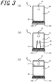
- FIGS. 3(a) to 3(c) are each a perspective view showing an example of the interior of the flow path provided in the embodiment of the light-irradiating device according to the disclosure.
- the gas supply section 3 preferably includes a porous member 25 disposed on a flow path 21 side of the discharging port 23. This makes it possible to restrain a non-uniform flow of gas in a location just before the discharging port 23, and thus discharge the gas in a uniform flow from the discharging port 23. Thus, uneven distribution of gas discharge toward the medium for printing can be reduced, with consequent improvement in the cure of the photo-curable material.
- porous member 25 it is possible to use any member, including various porous materials conforming to gas-discharge performance requirements, for providing a certain resistance against the passage of gas so as to restrain the gas from flowing in a non-uniform state.
- a member include net-like members (mesh members) such as a wire mesh including fine mesh openings relative to the open area ratio in the arrangement of the plurality of first openings 23a, hard porous members such as a pumice stone and porous ceramics, and fibrous porous members such as a woven fabric, a nonwoven fabric, and steel wool.
- the size, thickness, etc. of the porous member 25 may be appropriately adjusted according to the material used.
- the material quality does not necessarily have to be uniform throughout the porous member 25 over the entire discharging port 23, and thus a combination of a plurality of materials of varying quality may be used in conformance with the following design ideas adopted for the flow path.
- the porous member 25 may be either placed in contact with the plate-like member 24 provided with the discharging port 23 or spaced a short distance away from the plate-like member 24.
- the flow path 21 is preferably divided into a plurality of branches upstream from the discharging port 23.
- the distribution of gas supply occurs along the width of the flow path 21, the distribution can be adjusted according to the placement of such branches, and therefore it is possible to discharge the gas in a uniform flow from the discharging port 23, and thus reduce uneven distribution of gas discharge toward the medium for printing, ensuring improvement in the cure of the photo-curable material.
- the branches may be obtained by setting a plurality of flow-adjusting plates 26 in the interior of a part of the flow path 21 which extends along the side surface 9b of the housing 9.
- each flow-adjusting plate 26 is arranged so as to be inclined toward the corresponding end of the flow path from the center thereof in the width direction with respect to the direction of gas flow. This allows the gas from the supply port 22 located at the center of the flow path 21 in the width direction to flow more smoothly toward each end area than toward the central area within the flow path 21, and thus permits regulation of the flow of gas which tends to travel exclusively toward the center of the arrangement of the discharging port 23.
- Such flow-adjusting plates 26 may either be arranged parallel to the direction of gas flow or be arranged at random intervals in the direction of width of the flow path 21.
- means for constituting the branches is not limited to plate-like members such as the flow-adjusting plates 26.
- wide members arranged in a direction perpendicular to the direction of gas flow may define branches of reduced width dimension.
- such a flow path including a plurality of branches may be combined with the porous members 25 having different characteristics arranged in correspondence with the branches.
- the flow path 21 is preferably provided with a second porous member 27 spaced at a predetermined distance upstream from the discharging port 23.
- the second porous member 27 positioned upstream from the discharging port 23 in closer vicinity to the supply port 22, it is possible to discharge the gas in a uniform flow from the discharging port 23, and thus reduce uneven distribution of gas discharge toward the medium for printing, ensuring improvement in the cure of the photo-curable material.
- the second porous member 27 may be formed of a material similar to the material used for the porous member 25.
- the second porous member 27 is preferably dimensioned to extend over the entire area of the section of the flow path 21.
- the thickness of the second porous member 27 may be appropriately adjusted according to the material used and the material quality.
- a plurality of materials may be used in combination in the width or thickness direction of the flow path 21.
- porous member 25 the flow-adjusting plates 26 for dividing the flow path into branches, and the second porous member 27 shown in FIGS. 3(a) to 3(c) may be used alone or in combination.
- the flow path 21 is preferably constituted of a plurality of mutually connected plate-like members 24.
- the plurality of plate-like members 24 constituting the flow path 21 and the housing 9 may be formed of the same material. In this case, it is possible to suppress the occurrence of separation of the flow path 21 from the housing 9 due to the difference in thermal expansion between the plate-like member 24 and the housing 9.
- the plate-like member 24 shared with the housing 9 is treated as the housing 9.
- the plurality of plate-like members 24 constituting the flow path 21 and the housing 9 may be formed of different materials when the plate-like members 24 are substantially equal in thermal conductivity to the housing 9.
- the plurality of plate-like members 24 constituting the flow path 21 include a first plate-like member 24a located nearest to the irradiating opening 10 and a second plate-like member 24b located nearest to the medium for printing.
- the first plate-like member 24a is preferably arranged along an edge of the irradiating opening 10. That is, in this embodiment, the irradiating opening 10 has a strip form extending from one end of the light-irradiating surface 9a to the other end thereof. Accordingly, the first plate-like member 24a is arranged, along the flow path 21-side edge of the irradiating opening 10, so as to extend in the width direction between one end and the other end of the light-irradiating surface 9a. This makes it possible to increase the degree of uniformity in the intensity distribution of light entering the medium for printing, e.g. light which has been emitted from the irradiating opening 10, then reflected from the first plate-like member 24a, and entered the medium for printing.
- the first plate-like member 24a preferably is inclined so as to be away from the irradiating opening 10 as going from the light-irradiating surface 9a toward a light-irradiating direction.
- the first plate-like member 24a may be inclined so that the flow path 21 becomes narrower gradually with increasing proximity to the medium for printing. This makes it possible to restrain the light applied through the light-irradiating surface 9a from being blocked by the first plate-like member 24a.
- a surface of the first plate-like member 24a on the irradiating opening 10 side is preferably in a state of reflecting light from the light-emitting element 4. More specifically, preferably, the first plate-like member 24a is formed of a metal material, and the surface on the irradiating opening 10 side may be relatively close to a mirror surface. Thus, since light entering the first plate-like member 24a through the irradiating opening 10 can be reflected toward the medium for printing, it is possible to achieve improvement in the cure of the photo-curable material.
- the second plate-like member 24b located on the bottom side of the light-irradiating device 1 is provided with the discharging port 23.
- the distance between the medium for printing and the discharging port 23 can be reduced.
- the second plate-like member 24b may be parallel to the light-irradiating surface 9a.
- the light-irradiating surface 9a is opposed in parallel to the medium for printing.
- the gas can be discharged and sprayed on the medium for printing at the shortest distance.
- FIG. 4 is a front view schematically showing the structure of an embodiment of a printing device according to the disclosure.
- the printing device 100 shown as the embodiment in FIG. 4 includes a printing section 130 which carries out printing on a medium for printing 110 which is being conveyed by a conveying section 120, and the light-irradiating device 1 according to the disclosure which applies light to the medium for printing 110 under conveyance following the completion of the printing. Since a printing ink used in the printing section 130 is a photo-curable ink, the medium for printing 110 printed with the ink constitutes a photo-curable material.
- the printing device 100 includes: the light cure device according to the disclosure including the light-irradiating device 1 according to the disclosure and the conveying section 120 which conveys the photo-curable material which is irradiated with light from the irradiating opening 10 under the supply of gas from the discharging port 23 of the light-irradiating device 1; and the printing section 130 which prints photo-curable ink 131 on the medium for printing 110 as the photo-curable material.
- the photo-curable ink 131 is adherently applied to the medium for printing 110 which is being conveyed by the conveying section 120, and subsequently the photo-curable ink 131 is cured by the light-irradiating device 1, whereby printing can be carried out on the medium for printing 110 as desired.
- the light-irradiating device 1 since the light-irradiating device 1 applies light while releasing oxygen-free gas of satisfactory distribution into between the device and the medium for printing 110, this makes it possible to carry out cure under light while reducing curing reaction-inhibiting oxygen in the atmosphere, and thereby achieve improvement in the cure of the photo-curable ink 131.
- the alternate long and short dashed lines drawn from the irradiating opening 10 indicate a range of light irradiation, and the dashed arrow depicted below the gas supply section 3 indicates a direction of gas discharge.
- the conveying section 120 enables the medium for printing 110 to pass successively through the printing section 130 and the light-irradiating device 1 in the order named.
- the conveying section 120 including a pair of conveying rollers which are located so as to face each other and are rotatably supported, and also, on an as needed basis, a support table which is movable while carrying the medium for printing 110.
- the conveying section 120 feeds the medium for printing 110 into between the pair of conveying rollers, and then rotates the conveying rollers, ensuring the delivery of the medium for printing 110 in a conveyance direction.
- the printing section 130 has a function of printing the photo-curable ink 131 in a desired pattern on the medium for printing 110 which is being conveyed by the conveying section 120, constituting the photo-curable material.
- the printing section 130 which may be constructed of an ink-jet (IJ) head, is configured to direct a discharge of photo-curable ink droplets toward the medium for printing 110, ensuring that the droplets are applied adherently to the medium for printing 110.
- IJ ink-jet
- ultraviolet-curable ink is adopted as the photo-curable ink 131.
- a photoresist or photo-curable resin can also be used.
- a line-type IJ head is exemplified as the printing section 130
- the printing section 130 is not limited to this.
- a serial-type IJ head may be adopted.
- an offset printing machine, a flexographic printing machine, a screen printing machine, or the like that employ ultraviolet-curable ink may be adopted.
- the conveying section 120 conveys the medium for printing 110 in the conveyance direction which is a direction from right to left, as viewed in the drawing.
- the printing section 130 directs a discharge of, for example, ultraviolet-curable ink 131, toward the medium for printing 110 under conveyance, ensuring that the ink 131 adheres to the surface of the medium for printing 110.
- the ink 131 may be caused to adhere to either the entire area or part of the surface of the medium for printing 110 in any desired pattern.
- the ultraviolet-curable ink 131 printed on the medium for printing 110 is cured under irradiation of ultraviolet light from the light-irradiating device 1.
- the light cure device and the printing device 100 according to the disclosure benefit from the above-described advantageous effects achieved by the light-irradiating device 1 according to the disclosure.
- the light-irradiating device 1 and the printing section 130 are arranged with the gas supply section 3 of the light-irradiating device 1 lying in between.
- the gas supply section 3 is located between the light-irradiating section 2 and the printing section 130, this makes it possible to reduce the occurrence of clogging in the discharge hole of the printing section 130 caused by entry of the light from the light-irradiating section 2 to the printing section 130.
- a control section 140 connected to the light-irradiating device 1 has a function of controlling light emission of the light-irradiating device 1.
- the control section 140 includes a memory therein, and the memory stores information indicating characteristics of light that allows relatively good cure of the photo-curable ink 131 discharged from the IJ head serving as the printing section 130.
- the stored information include numerical values representing wavelength distribution characteristics and light emission intensity (emission intensity of light in each wavelength range) suited to the cure of the photo-curable ink 131 discharged in droplet form.
- the printing device 100 is also capable of adjusting, on the basis of the information stored in the control section 140, the magnitude of drive current which is inputted to a plurality of the light-emitting elements 4 serving as a light source.
- the light-irradiating device 1 can apply light of adequate quantity in accordance with the characteristics of the ink 131 in use, and this enables the photo-curable ink 131 to be cured with light of relatively low energy.
- the printing device 100 using an IJ head as the printing section 130 includes the light-irradiating device 1
- the light-irradiating device 1 is also applicable to various resin-curing devices as a light cure device for curing a photo-curable material, such as a material in which a paste such as resist is spin-coated on the surface of an object or a material in which a photo-curable resin is screen-printed, under conveyance by light irradiation.
- the light-irradiating device, the light cure device, and the printing device according to the disclosure since it is possible to achieve a reduction of non-uniform flow of gas which has been supplied from the flow path and then discharged from the discharging port, and thus to achieve a reduction of curing reaction-inhibiting atmospheric oxygen in the vicinity of the photo-curable material such as the medium for printing, it is possible to achieve improvement in the cure of the photo-curable material.
Landscapes
- Health & Medical Sciences (AREA)
- General Health & Medical Sciences (AREA)
- Toxicology (AREA)
- Engineering & Computer Science (AREA)
- Mechanical Engineering (AREA)
- Supply, Installation And Extraction Of Printed Sheets Or Plates (AREA)
- Ink Jet (AREA)
- Led Device Packages (AREA)
- Steering Control In Accordance With Driving Conditions (AREA)
- Non-Portable Lighting Devices Or Systems Thereof (AREA)
- Heating, Cooling, Or Curing Plastics Or The Like In General (AREA)
Abstract
Description
- The present disclosure relates to a light-irradiating device that can be used to cure an ultraviolet-curable resin, ink, etc., and also relates to a printing device including the same.
- Among light-irradiating devices of the type including a light source and a drive substrate for driving the light source each received in a housing, there are some that employ, for example, a lamp or LED (Light Emitting Diode) designed for ultraviolet emission as the light source. Such a light-irradiating device capable of ultraviolet irradiation finds extensive application in various fields, for example, in addition to a printing field for purposes of the cure of a photo-curable material (resin, ink, etc.), etc., a medical-related field for purposes of disinfection, etc., a manufacturing-assembly field for purposes of the cure of an adhesive or an ultraviolet-curable resin in the process of mounting electronic components, etc., and a drying treatment field for purposes of efficient drying of an object under infrared irradiation, etc. (refer to Japanese Unexamined Patent Publication
JP-A 2008-244165 - In the printing field, in particular, the capability of rapid cure of a photo-curable material is demanded, but radicals generated in the process of application of light to a photo-curable material may react with atmospheric oxygen, which may inhibit a curing reaction of resin or ink.
- There has been a growing demand for a light-irradiating device that achieves improvement in the cure of a photo-curable material by reducing oxygen in an atmosphere for cure.
- A light-irradiating device according to the disclosure includes: a light-emitting element; a housing in which the light-emitting element is disposed, the housing including a light-irradiating surface provided with an irradiating opening which is capable of allowing light from the light-emitting element to pass therethrough; a flow path configured to supply gas, the flow path including an end located near the irradiating opening of the light-irradiating surface of the housing; and a discharging port configured to discharge the gas, the discharging port being disposed at the end of the flow path, the discharging port including a plurality of first openings arranged in a width direction of the irradiating opening in correspondence with the irradiating opening, and a second opening positioned in correspondence with each end in the width direction of the irradiating opening.
- A light cure device according to the disclosure includes: the light-irradiating device according to the disclosure; and a conveying section configured to convey a photo-curable material to which the gas from the discharging port of the light-irradiating device is supplied and which is irradiated with light from the irradiating opening.
- A printing device according to the disclosure includes: the light cure device according to the disclosure; and a printing section configured to print photo-curable ink on a medium for printing as the photo-curable material.
-
-
FIG. 1(a) is a side view of an embodiment of a light-irradiating device according to the disclosure, andFIG. 1(b) is a bottom view thereof; -
FIG. 2(a) is a plan view of a light-irradiating section of the light-irradiating device shown inFIG. 1 , andFIG. 2(b) is a sectional view thereof; -
FIGS. 3(a) to 3(c) are each a perspective view showing an example of the interior of a flow path in the embodiment of the light-irradiating device according to the disclosure; and -
FIG. 4 is a front view schematically showing the structure of an embodiment of a printing device according to the disclosure. - Embodiments of a light-irradiating device, a light cure device, and a printing device according to the disclosure will now be described with reference to drawings. Following is for purposes of illustration of the embodiments of the disclosure, and hence the disclosure is not limited to the following embodiments.
- An embodiment of the light-irradiating device according to the disclosure is schematically shown in
FIG. 1. FIG. 1(a) is a side view of the light-irradiating device, andFIG. 1(b) is a bottom view thereof. - The light-irradiating device 1 is configured to cure a photo-curable material by the irradiation of light (e.g. ultraviolet light). The light-irradiating device 1 is installed as a light cure device in a printing device such as an offset printing device or an ink-jet printing device. According to such a configuration, the printing device can print a photo-curable material (e.g. photo-curable ink such as ultraviolet-curable ink) on a medium for printing by applying the photo-curable material adherently onto the medium for printing by a printing section of the printing device, and thereafter curing the photo-curable material by the light-irradiating device 1.
- The light-irradiating device 1 includes a light-irradiating section 2 and a
gas supply section 3. In the light-irradiating device 1 according to the disclosure including the light-irradiating section 2 and thegas supply section 3, in the process of curing a photo-curable material, while thegas supply section 3 is supplying a gaseous material (gas) into between the light-irradiating device 1 and the medium for printing, the light-irradiating section 2 can carry out light application. This makes it possible to reduce the occurrence of a reaction between radicals and atmospheric oxygen by using oxygen-free gas, e.g. nitrogen gas, as the gas, and thereby achieve improvement in the cure of the photo-curable material. The light-irradiating device 1 may be produced by a heretofore known method. - The light-irradiating section 2 is internally provided with a light-emitting
element 4 and can apply light to the non-illustrated medium for printing or the like. The light-irradiating section 2 includes the light-emittingelement 4, asubstrate 5 on which the light-emittingelement 4 is mounted, aheat sink 6 serving as a heat-dissipating member which is thermally connected to thesubstrate 5, acooling fan 7 capable of blowing air on theheat sink 6, adrive substrate 8 which drives the light-emittingelement 4, and ahousing 9 which receives the aforenamed components therein. Thehousing 9 includes, at a bottom thereof, a light-irradiatingsurface 9a provided with anirradiating opening 10 which is capable of allowing light to pass therethrough to permit external irradiation of light from the light-emittingelement 4. - Moreover, the
housing 9 is provided with a plurality ofventilating slots 11 which is capable of supplying and discharging external air therethrough for enhancing heat-dissipation effect of theheat sink 6. One or some of theventilating slots 11 are provided with afilter 12. Moreover, via one or some of theventilating slots 11, there is provided aconnector 13, which is electrically connected to thedrive substrate 5, for external supply of power and driving signals to thedrive substrate 8. - The light-emitting
element 4 of the light-irradiating device 1 is schematically shown inFIGS. 2(a) and 2(b). FIG. 2(a) is a schematic plan view showing the light-emittingelement 4 and thesubstrate 5 as viewed in plan.FIG. 2(b) is a schematic sectional view showing the light-emittingelement 4 and thesubstrate 5 as viewed in section. - The light-emitting
element 4 can emit light (ultraviolet light). The light-emittingelement 4 includes a plurality of semiconductor layers and a pair of electrodes. The plurality of semiconductor layers include an active layer, a p-type cladding layer, and an n-type cladding layer, and can emit light by applying a voltage via the pair of electrodes. For example, the plurality of semiconductor layers may be formed of gallium arsenide (GaAs) or gallium nitride (GaN). For example, the pair of electrodes may be formed of silver (Ag). - For example, Examples of the light-emitting
element 4 may include an LD (Laser Diode) and LED. For example, the light-emittingelement 4 may emits light of wavelengths in the ultraviolet region. More specifically, for example, a peak of the light spectrum may be from 280 nm to 440 nm. The wavelength of light from the light-emittingelement 4 may be at any level needed to cure a photo-curable material. - The
substrate 5 can support the light-emittingelement 4. For example, thesubstrate 5 may have an exterior shape of a flat plate. For example, thesubstrate 5 may be rectangular in plan configuration. Thesubstrate 5 is provided with a plurality of recesses, and the light-emittingelement 4 is mounted in each recess. For example, an opening of the recess may be circularly shaped. Thesubstrate 5 does not necessarily have to be provided with the recesses. In this case, the light-emittingelement 4 may be mounted on an upper surface of the flat-shaped substrate 5. - The
substrate 5 is constituted of a single insulating layer or a plurality of insulating layers. In other words, thesubstrate 5 includes a single insulating layer or a plurality of insulating layers. Examples of a material for the insulating layer may include ceramics such as an aluminum oxide sintered body, an aluminum nitride sintered body, a mullite sintered body, or glass ceramics, and resin such as an epoxy resin or a liquid crystal polymer. - The
substrate 5 further includes wiring which is electrically connected to the light-emittingelement 4 via a bonding wire, for example. Examples of the material for the wiring may include tungsten(W), molybdenum (Mo), manganese (Mn), and copper (Cu). - The light-emitting
element 4 of this embodiment is sealed within the recess of thesubstrate 5 with a sealing material. Examples of the sealing material may include a silicone resin. The sealing material does not necessarily have to be provided for the light-emittingelement 4. - As shown in
FIG. 1(a) , thehousing 9 includes the light-emittingsurface 9a at a bottom thereof. The light-irradiatingsurface 9a is provided with theirradiating opening 10 which is capable of transmitting light from the light-emittingelement 4 mounted within thehousing 9 therethrough, and is a surface opposed to the medium for printing. Consequently, light from the mounted light-emittingelement 4 can be applied to the medium for printing through theirradiating opening 10 of the light-irradiatingsurface 9a. As a rule, theirradiating opening 10 is provided with a light-transmitting member formed of glass or the like, as a cover member. Although there is no need for the light-transmitting member to be transmitted to light of each and every wavelength, preferably, the light-transmitting member may be capable of transmitting at least light having a wavelength required for curing the photo-curable material with an amount of light required for curing. - In the case where the
housing 9 is designed for downward emission of irradiation light from the light-emittingelement 4 through the light-irradiatingsurface 9a, for example, thehousing 9 measures about 150 mm in vertical dimension, about 100 mm in horizontal dimension as viewed inFIG. 1(a) , and about 80 mm in depth-wise dimension. Thehousing 9 may be given any exterior shape suited to the intended use of the light-irradiating device 1. Examples of the exterior shape include a cubic shape, a triangular prism shape, a circular cylindrical shape, and a semicircular column shape. Thehousing 9 in this embodiment includes a slanted surface at a top thereof, and thefilter 12 is disposed at theventilating slot 11 provided in the slanted surface. Thus, thehousing 9 is capable of efficient supply and discharge of air in relation to the coolingfan 7. -
FIG. 1(b) shows the light-irradiatingsurface 9a of thehousing 9.FIG. 1(b) is a bottom view of thehousing 9, as seen from the light-irradiatingsurface 9a side. The dotted lines depicted in the drawing indicate the exterior shape of the light-irradiatingsurface 9a. - A part of the light-irradiating
surface 9a other than the irradiatingopening 10 may be formed as a light-blocking region. In this case, the light-irradiatingsurface 9a includes the irradiatingopening 10 which is capable of allowing light from the light-emittingelement 4 to pass therethrough, and non-light passing portions (unmarked) that are light-blocking regions arranged with the irradiatingopening 10 lying in between. In this embodiment, as shown inFIG. 1(b) , the light-irradiatingsurface 9a includes the irradiatingopening 10 and the non-light passing portions. The non-light passing portion does not necessarily have to have a light-blocking property with respect to light of each and every wavelength, and need only be capable of blocking light of certain wavelength that is passed through the irradiatingopening 10. Moreover, depending on the design requirements for the light-irradiating section 2, the non-light passing portion may be formed so as to surround the irradiatingopening 10. - For example, the irradiating
opening 10 has the form of a rectangular opening, and may be provided with a plate-like cover member formed of a light-transmittable material as required. In this embodiment, thehousing 9 is, except at the irradiatingopening 10, formed of a light-blocking material. A surface of thehousing 9 opposed to the medium for printing is provided with an opening which serves as the irradiatingopening 10. With the cover member fitted in this opening, the light-irradiatingsurface 9a provided with the irradiatingopening 10 is constituted. - For example, the light-irradiating
surface 9a may be formed as a flat surface. Moreover, for example, the light-irradiatingsurface 9a may be rectangular-shaped. - In the case where the light-irradiating
surface 9a includes the irradiatingopening 10 and the non-light passing portion, for example, the irradiatingopening 10 may be given either a rectangular form or a strip-like form. Moreover, the irradiatingopening 10 may be shaped so as to extend from one of the ends in the width direction of the light-irradiatingsurface 9a to the other end. Alternatively, the irradiatingopening 10 may be dimensioned to fit within the light-irradiatingsurface 9a. In this case, part of the light-irradiatingsurface 9a lies outside each end of the irradiatingopening 10. - Examples of a material for the cover member fitted in the irradiating
opening 10 include quartz glass and BK7. Examples of a material for the non-light passing portion include aluminum (Al), stainless steel (SUS), and copper (Cu). In this embodiment, thehousing 9 is, except at the irradiatingopening 10, formed of the same material as a material constituting the non-light passing portion. Thehousing 9 may be, except at the light-irradiatingsurface 9a, formed of a material which differs from a material constituting the non-light passing portion. In this case, the housing 9 (exclusive of the light-irradiatingsurface 9a) is formed of aluminum (Al), stainless steel (SUS), or copper (Cu), for example. - As described above, the
gas supply section 3 is capable of feeding gas, preferably, an inert gas such as an oxygen-free nitrogen (N2) gas, to a space on a light-irradiatingsurface 9a side between the medium for printing and the light-irradiating device 1. By supplying the oxygen-free gas from the light-irradiatingsurface 9a side, it is possible to reduce the concentration of oxygen in an atmosphere surrounding the photo-curable material placed so as to face the light-irradiatingsurface 9a, for example, the photo-curable material printed on the medium for printing, and thereby reduce the occurrence of a reaction between oxygen and radicals resulting from application of light to the photo-curable material. Consequently, the factor that inhibits the curing reaction of the photo-curable material can be eliminated, with consequent improvement in the cure of the photo-curable material. - As shown in
FIGS. 1(a) and 1(b) , thegas supply section 3 includes: aflow path 21, asupply port 22 disposed at the top of theflow path 21, and a dischargingport 23 disposed at the bottom of theflow path 21. The gas supplied to thegas supply section 3 through thesupply port 22 flows within theflow path 21, and is discharged from the dischargingport 23. The gas discharged from the dischargingport 23 is supplied to the space between the medium for printing and the light-irradiatingsurface 9a side of the light-irradiating device 1. For example, the supplied gas is preferably an inert gas such as a nitrogen (N2) gas or an argon (Ar) gas. The supplied gas may be any gas which substantially contains no oxygen or any inert gas which is less reactive with radicals contained in the photo-curable material. - The
flow path 21 includes a plurality of plate-like members 24. Theflow path 21 in this case is constituted of the plurality of plate-like members 24. More specifically, a space surrounded by the plurality of mutually connected plate-like members 24 serves as theflow path 21. Examples of a material for forming theflow path 21 may include metal materials such as aluminum (Al), stainless steel (SUS), and copper (Cu), and resin materials such as an acrylic resin. - The
gas supply section 3 is secured to the light-irradiating section 2 by fastening one or some of a plurality of the plate-like members 24 of theflow path 21 to thehousing 9. One or some of the plurality of plate-like members 24 are adhesively bonded, screw-held, or otherwise fastened to thehousing 9. With part of theflow path 21 fixedly contacted by thehousing 9 in this way, it is also possible to improve heat dissipation from thehousing 9 by the gas supplied to theflow path 21. - The
supply port 22 and the dischargingport 23 are located at both ends of theflow path 21. Openings surrounded by the plurality of plate-like members 24 may serve as thesupply port 22 and the dischargingport 23, or openings formed in one of a plurality of the plate-like members 24 may serve as thesupply port 22 and the dischargingport 23. Thesupply port 22 is connected to a gas supply source. - The
flow path 21 is arranged so that an end thereof is located near the irradiatingopening 10 of the light-irradiatingsurface 9a of thehousing 9. Theflow path 21 does not necessarily have to be shaped so as to be folded over onto the light-irradiatingsurface 9a. For example, theflow path 21 may be positioned so that the end thereof is located next to the light-irradiatingsurface 9a. The dischargingport 23 located at the end of theflow path 21 includes: a plurality offirst openings 23a which are each provided in the end of theflow path 21 so as to extend in the irradiation direction of light from the irradiatingopening 10, and are arranged in the width direction of the irradiatingopening 10 in correspondence with the irradiatingopening 10; and asecond opening 23b which is arranged in correspondence with each end in the width direction of the irradiatingopening 10. - In this embodiment, the plurality of
first openings 23a are each shaped in a circular hole, and are arranged along the width of the irradiatingopening 10 in such a pattern as to cover a region to be irradiated with light. The alternate long and short dashed lines shown inFIG. 1(b) indicate the range of an area in which thefirst openings 23a are arranged. Within this range, thefirst openings 23a of varying sizes and shapes may be arranged in various patterns with consideration given to gas discharge distribution, etc. For example, the plurality offirst openings 23a can be efficiently formed by punching processing. Meanwhile, thesecond opening 23b is positioned as a narrow elongate form such as a slit form in conformity with the area in which thefirst openings 23a are arranged so as to be located in correspondence with each end in the width direction of the irradiatingopening 10. Since the dischargingport 23 includes such asecond opening 23b, although the amount of gas supplied at both ends in the width direction tends to be lower than at the center only by the emission from the first openings arranged over the width direction, a sufficient amount of gas supply can be secured at the both ends. This makes it possible to reduce uneven distribution of gas supply to the space between the light-irradiatingsurface 9a and the medium for printing subjected to light irradiation, and thus enables satisfactory curing reaction to occur throughout the entire area of the region to be irradiated with light, with consequent improvement in curability. - Although the
gas supply section 3 is made larger in width than the light-irradiating section 2 in this embodiment, this does not constitute any structural limitation. There may be a case where a plurality of the light-irradiating devices 1 are arranged and combined into one system for use. In this case, thegas supply section 3 may be set to have a width which is less than or equal to the width of the light-irradiating section 2, so that gas supply is carried out via the arrangement of thefirst openings 23a and thesecond openings 23b as a whole set in correspondence with the width of the irradiatingopening 10. Even if the entire arrangement of the first andsecond openings opening 10, the flow of supplied gas spreads widely, and thus the gas can be supplied satisfactorily into an atmosphere in the region irradiated with light from the irradiatingopening 10. - The
flow path 21 in this embodiment is arranged so that an end thereof is located near the irradiatingopening 10 of the light-irradiatingsurface 9a. That is, one or some of the plate-like members 24 of theflow path 21 are kept in contact with the light-irradiatingsurface 9a. In a light-irradiating device of the related art, for example, a photo-curable material adhering to the irradiatingopening 10 may absorb light and consequently generate heat, which results in a fracture in a cover glass, for example. By contrast, since the light-irradiating device 1 according to the disclosure includes the above constitution, theflow path 21 for gas which is supplied whenever necessary is disposed on part of the light-irradiatingsurface 9a, and this can improve heat dissipation from the light-irradiatingsurface 9a. Thus, it is possible to suppress the occurrence of fracture in the light-irradiatingsurface 9a. In this embodiment, the light-irradiatingsurface 9a includes the irradiatingopening 10 and the non-light passing portion, and, theflow path 21 is connected to the non-light passing portion alone. - The irradiating
opening 10 may be displaced from the center of the light-irradiatingsurface 9a in the opposite direction to the location of theflow path 21. This makes it possible to increase the area of the non-light passing portion where theflow path 21 is located, and thus improve heat dissipation from the light-irradiatingsurface 9a. Alternatively, the irradiatingopening 10 may be located at the center of the light-irradiatingsurface 9a. The placement of the irradiatingopening 10 is determined in conformance with design requirements. - Some of the plurality of plate-
like members 24 constituting theflow path 21 may constitute thehousing 9. In this case, the surface of thehousing 9 can be exposed directly to the gas flowing within theflow path 21, with consequent improvement in heat dissipation from thehousing 9. - Moreover, the
housing 9 includes aside surface 9b connected to the light-irradiatingsurface 9a, and theflow path 21 is preferably disposed so as to extend from theside surface 9b of thehousing 9 to the light-irradiatingsurface 9a. That is, as shown inFIG. 1(a) , it is preferable that thehousing 9 includes theside surface 9b connected to the light-irradiatingsurface 9a, and theflow path 21 is connected to theside surface 9b of thehousing 9, and is arranged so as to extend from theside surface 9b to the light-irradiatingsurface 9a. Consequently, by the gas flowing within theflow path 21, it is possible to improve heat dissipation not only from the light-irradiatingsurface 9a of thehousing 9 but also from theside surface 9b of thehousing 9. Moreover, even if theflow path 21 is not shaped so as to be folded over onto the light-irradiatingsurface 9a as described earlier, improvement in heat dissipation from theside surface 9b of thehousing 9 can be achieved. - In order to discharge the gas uniformly from the discharging
port 23, various design ideas can be adopted in the implementation of theflow path 21 of thegas supply section 3. A few examples of the design of the flow path are shown inFIG. 3. FIGS. 3(a) to 3(c) are each a perspective view showing an example of the interior of the flow path provided in the embodiment of the light-irradiating device according to the disclosure. - As shown in
FIG. 3(a) , thegas supply section 3 preferably includes aporous member 25 disposed on aflow path 21 side of the dischargingport 23. This makes it possible to restrain a non-uniform flow of gas in a location just before the dischargingport 23, and thus discharge the gas in a uniform flow from the dischargingport 23. Thus, uneven distribution of gas discharge toward the medium for printing can be reduced, with consequent improvement in the cure of the photo-curable material. - As such
porous member 25, it is possible to use any member, including various porous materials conforming to gas-discharge performance requirements, for providing a certain resistance against the passage of gas so as to restrain the gas from flowing in a non-uniform state. Examples of such a member include net-like members (mesh members) such as a wire mesh including fine mesh openings relative to the open area ratio in the arrangement of the plurality offirst openings 23a, hard porous members such as a pumice stone and porous ceramics, and fibrous porous members such as a woven fabric, a nonwoven fabric, and steel wool. The size, thickness, etc. of theporous member 25 may be appropriately adjusted according to the material used. Moreover, the material quality does not necessarily have to be uniform throughout theporous member 25 over the entire dischargingport 23, and thus a combination of a plurality of materials of varying quality may be used in conformance with the following design ideas adopted for the flow path. - In the case where the
porous member 25 is located, on aflow path 21 side of the dischargingport 23, theporous member 25 may be either placed in contact with the plate-like member 24 provided with the dischargingport 23 or spaced a short distance away from the plate-like member 24. - Next, as shown in
FIG. 3(b) , in thegas supply section 3, theflow path 21 is preferably divided into a plurality of branches upstream from the dischargingport 23. Although immediately after the supply of gas from thesupply port 22, the distribution of gas supply occurs along the width of theflow path 21, the distribution can be adjusted according to the placement of such branches, and therefore it is possible to discharge the gas in a uniform flow from the dischargingport 23, and thus reduce uneven distribution of gas discharge toward the medium for printing, ensuring improvement in the cure of the photo-curable material. - For example, the branches may be obtained by setting a plurality of flow-adjusting
plates 26 in the interior of a part of theflow path 21 which extends along theside surface 9b of thehousing 9. In this embodiment, each flow-adjustingplate 26 is arranged so as to be inclined toward the corresponding end of the flow path from the center thereof in the width direction with respect to the direction of gas flow. This allows the gas from thesupply port 22 located at the center of theflow path 21 in the width direction to flow more smoothly toward each end area than toward the central area within theflow path 21, and thus permits regulation of the flow of gas which tends to travel exclusively toward the center of the arrangement of the dischargingport 23. Such flow-adjustingplates 26 may either be arranged parallel to the direction of gas flow or be arranged at random intervals in the direction of width of theflow path 21. Moreover, means for constituting the branches is not limited to plate-like members such as the flow-adjustingplates 26. For example, wide members arranged in a direction perpendicular to the direction of gas flow may define branches of reduced width dimension. Moreover, for adjustment to the distribution of gas discharge from the dischargingport 23, such a flow path including a plurality of branches may be combined with theporous members 25 having different characteristics arranged in correspondence with the branches. - Next, as shown in
FIG. 3(c) , in thegas supply section 3, theflow path 21 is preferably provided with a secondporous member 27 spaced at a predetermined distance upstream from the dischargingport 23. Thus, since uneven distribution of gas supply from thesupply port 22 can be adjusted by the secondporous member 27 positioned upstream from the dischargingport 23 in closer vicinity to thesupply port 22, it is possible to discharge the gas in a uniform flow from the dischargingport 23, and thus reduce uneven distribution of gas discharge toward the medium for printing, ensuring improvement in the cure of the photo-curable material. - The second
porous member 27 may be formed of a material similar to the material used for theporous member 25. The secondporous member 27 is preferably dimensioned to extend over the entire area of the section of theflow path 21. The thickness of the secondporous member 27 may be appropriately adjusted according to the material used and the material quality. Moreover, as the material and the material quality of the secondporous member 27, a plurality of materials may be used in combination in the width or thickness direction of theflow path 21. - The
porous member 25, the flow-adjustingplates 26 for dividing the flow path into branches, and the secondporous member 27 shown inFIGS. 3(a) to 3(c) may be used alone or in combination. - Next, the
flow path 21 is preferably constituted of a plurality of mutually connected plate-like members 24. This affords flexibility in the formation of theflow path 21. The plurality of plate-like members 24 constituting theflow path 21 and thehousing 9 may be formed of the same material. In this case, it is possible to suppress the occurrence of separation of theflow path 21 from thehousing 9 due to the difference in thermal expansion between the plate-like member 24 and thehousing 9. In the case where one of the plate-like members 24 constituting theflow path 21 constitutes thehousing 9, the plate-like member 24 shared with thehousing 9 is treated as thehousing 9. The plurality of plate-like members 24 constituting theflow path 21 and thehousing 9 may be formed of different materials when the plate-like members 24 are substantially equal in thermal conductivity to thehousing 9. - The plurality of plate-
like members 24 constituting theflow path 21 include a first plate-like member 24a located nearest to the irradiatingopening 10 and a second plate-like member 24b located nearest to the medium for printing. - The first plate-
like member 24a is preferably arranged along an edge of the irradiatingopening 10. That is, in this embodiment, the irradiatingopening 10 has a strip form extending from one end of the light-irradiatingsurface 9a to the other end thereof. Accordingly, the first plate-like member 24a is arranged, along the flow path 21-side edge of the irradiatingopening 10, so as to extend in the width direction between one end and the other end of the light-irradiatingsurface 9a. This makes it possible to increase the degree of uniformity in the intensity distribution of light entering the medium for printing, e.g. light which has been emitted from the irradiatingopening 10, then reflected from the first plate-like member 24a, and entered the medium for printing. - The first plate-
like member 24a preferably is inclined so as to be away from the irradiatingopening 10 as going from the light-irradiatingsurface 9a toward a light-irradiating direction. In other words, the first plate-like member 24a may be inclined so that theflow path 21 becomes narrower gradually with increasing proximity to the medium for printing. This makes it possible to restrain the light applied through the light-irradiatingsurface 9a from being blocked by the first plate-like member 24a. - A surface of the first plate-
like member 24a on the irradiatingopening 10 side is preferably in a state of reflecting light from the light-emittingelement 4. More specifically, preferably, the first plate-like member 24a is formed of a metal material, and the surface on the irradiatingopening 10 side may be relatively close to a mirror surface. Thus, since light entering the first plate-like member 24a through the irradiatingopening 10 can be reflected toward the medium for printing, it is possible to achieve improvement in the cure of the photo-curable material. - The second plate-
like member 24b located on the bottom side of the light-irradiating device 1 is provided with the dischargingport 23. Thus, the distance between the medium for printing and the dischargingport 23 can be reduced. - In the case where the discharging
port 23 is disposed in the second plate-like member 24b, the second plate-like member 24b may be parallel to the light-irradiatingsurface 9a. As a rule, the light-irradiatingsurface 9a is opposed in parallel to the medium for printing. Thus, when the second plate-like member 24b is parallel to the light-irradiatingsurface 9a, the gas can be discharged and sprayed on the medium for printing at the shortest distance. -
FIG. 4 is a front view schematically showing the structure of an embodiment of a printing device according to the disclosure. Theprinting device 100 shown as the embodiment inFIG. 4 includes aprinting section 130 which carries out printing on a medium for printing 110 which is being conveyed by a conveyingsection 120, and the light-irradiating device 1 according to the disclosure which applies light to the medium for printing 110 under conveyance following the completion of the printing. Since a printing ink used in theprinting section 130 is a photo-curable ink, the medium for printing 110 printed with the ink constitutes a photo-curable material. The light-irradiating device 1 according to the disclosure and the conveyingsection 120 which conveys the photo-curable material to which the gas from the dischargingport 23 of the light-irradiating device 1 is supplied and which is irradiated with light from the irradiatingopening 10, make up a light cure device according to the disclosure. That is, theprinting device 100 according to the disclosure includes: the light cure device according to the disclosure including the light-irradiating device 1 according to the disclosure and the conveyingsection 120 which conveys the photo-curable material which is irradiated with light from the irradiatingopening 10 under the supply of gas from the dischargingport 23 of the light-irradiating device 1; and theprinting section 130 which prints photo-curable ink 131 on the medium for printing 110 as the photo-curable material. - In the
printing device 100, the photo-curable ink 131 is adherently applied to the medium for printing 110 which is being conveyed by the conveyingsection 120, and subsequently the photo-curable ink 131 is cured by the light-irradiating device 1, whereby printing can be carried out on the medium for printing 110 as desired. At this time, since the light-irradiating device 1 applies light while releasing oxygen-free gas of satisfactory distribution into between the device and the medium forprinting 110, this makes it possible to carry out cure under light while reducing curing reaction-inhibiting oxygen in the atmosphere, and thereby achieve improvement in the cure of the photo-curable ink 131. - In
FIG. 4 , the alternate long and short dashed lines drawn from the irradiatingopening 10 indicate a range of light irradiation, and the dashed arrow depicted below thegas supply section 3 indicates a direction of gas discharge. - The conveying
section 120 enables the medium for printing 110 to pass successively through theprinting section 130 and the light-irradiating device 1 in the order named. The conveyingsection 120 including a pair of conveying rollers which are located so as to face each other and are rotatably supported, and also, on an as needed basis, a support table which is movable while carrying the medium forprinting 110. The conveyingsection 120 feeds the medium for printing 110 into between the pair of conveying rollers, and then rotates the conveying rollers, ensuring the delivery of the medium for printing 110 in a conveyance direction. - The
printing section 130 has a function of printing the photo-curable ink 131 in a desired pattern on the medium for printing 110 which is being conveyed by the conveyingsection 120, constituting the photo-curable material. Theprinting section 130, which may be constructed of an ink-jet (IJ) head, is configured to direct a discharge of photo-curable ink droplets toward the medium forprinting 110, ensuring that the droplets are applied adherently to the medium forprinting 110. For example, ultraviolet-curable ink is adopted as the photo-curable ink 131. Alternatively, for example, a photoresist or photo-curable resin can also be used. - While, in this embodiment, a line-type IJ head is exemplified as the
printing section 130, theprinting section 130 is not limited to this. For example, a serial-type IJ head may be adopted. In another alternative, for example, as theprinting section 130, an offset printing machine, a flexographic printing machine, a screen printing machine, or the like that employ ultraviolet-curable ink may be adopted. - In the
printing device 100, the conveyingsection 120 conveys the medium for printing 110 in the conveyance direction which is a direction from right to left, as viewed in the drawing. Theprinting section 130 directs a discharge of, for example, ultraviolet-curable ink 131, toward the medium for printing 110 under conveyance, ensuring that theink 131 adheres to the surface of the medium forprinting 110. At this time, theink 131 may be caused to adhere to either the entire area or part of the surface of the medium for printing 110 in any desired pattern. In theprinting device 100, the ultraviolet-curable ink 131 printed on the medium forprinting 110 is cured under irradiation of ultraviolet light from the light-irradiating device 1. - The light cure device and the
printing device 100 according to the disclosure benefit from the above-described advantageous effects achieved by the light-irradiating device 1 according to the disclosure. - In the
printing device 100 according to this embodiment, the light-irradiating device 1 and theprinting section 130 are arranged with thegas supply section 3 of the light-irradiating device 1 lying in between. With this arrangement, since thegas supply section 3 is located between the light-irradiating section 2 and theprinting section 130, this makes it possible to reduce the occurrence of clogging in the discharge hole of theprinting section 130 caused by entry of the light from the light-irradiating section 2 to theprinting section 130. - A
control section 140 connected to the light-irradiating device 1 has a function of controlling light emission of the light-irradiating device 1. Thecontrol section 140 includes a memory therein, and the memory stores information indicating characteristics of light that allows relatively good cure of the photo-curable ink 131 discharged from the IJ head serving as theprinting section 130. - Specific examples of the stored information include numerical values representing wavelength distribution characteristics and light emission intensity (emission intensity of light in each wavelength range) suited to the cure of the photo-
curable ink 131 discharged in droplet form. By virtue of thecontrol section 140, theprinting device 100 according to this embodiment is also capable of adjusting, on the basis of the information stored in thecontrol section 140, the magnitude of drive current which is inputted to a plurality of the light-emittingelements 4 serving as a light source. Thus, according to theprinting device 100, the light-irradiating device 1 can apply light of adequate quantity in accordance with the characteristics of theink 131 in use, and this enables the photo-curable ink 131 to be cured with light of relatively low energy. - Moreover, while, in this embodiment, the
printing device 100 using an IJ head as theprinting section 130 includes the light-irradiating device 1, the light-irradiating device 1 is also applicable to various resin-curing devices as a light cure device for curing a photo-curable material, such as a material in which a paste such as resist is spin-coated on the surface of an object or a material in which a photo-curable resin is screen-printed, under conveyance by light irradiation. - In accordance with the light-irradiating device, the light cure device, and the printing device according to the disclosure, since it is possible to achieve a reduction of non-uniform flow of gas which has been supplied from the flow path and then discharged from the discharging port, and thus to achieve a reduction of curing reaction-inhibiting atmospheric oxygen in the vicinity of the photo-curable material such as the medium for printing, it is possible to achieve improvement in the cure of the photo-curable material.
- Although specific embodiments of the disclosure have been detailed herein, it is to be understood that the disclosure is not limited to the above-described embodiments, and hence various changes, modifications, and improvements may be made therein without departing from the gist of the disclosure.
-
- 1:Light-irradiating device
- 2: Light-irradiating section
- 3: Gas supply section
- 4: Light-emitting element
- 9: Housing
- 9a: Light-irradiating surface
- 9b: Side surface
- 10: Irradiating opening
- 21: Flow path
- 23: Discharging port
- 23a: First opening
- 23b: Second opening
- 24: Plate-like member
- 24a: First plate-like member
- 24b: Second plate-like member
- 25: Porous member
- 27: Second porous member
- 100: Printing device
- 110: Medium for printing
- 120: Conveying section
- 130: Printing section
- 131 Photo-curable ink (ink)
Claims (11)
- A light-irradiating device, comprising:a light-emitting element;a housing in which the light-emitting element is disposed, the housing comprising a light-irradiating surface provided with an irradiating opening which is capable of allowing light from the light-emitting element to pass therethrough;a flow path configured to supply gas, the flow path comprising an end located near the irradiating opening of the light-irradiating surface of the housing; anda discharging port configured to discharge the gas, the discharging port being disposed at the end of the flow path, the discharging port comprising a plurality of first openings arranged in a width direction of the irradiating opening in correspondence with the irradiating opening, and a second opening positioned in correspondence with each end in the width direction of the irradiating opening.
- The light-irradiating device according to claim 1, further comprising:
a porous member disposed on a flow path side of the discharging port. - The light-irradiating device according to claim 1,
wherein the flow path is divided into a plurality of branches upstream from the discharging port. - The light-irradiating device according to claim 1,
wherein the flow path is provided with a second porous member spaced at a predetermined distance upstream from the discharging port. - The light-irradiating device according to claim 1,
wherein the housing comprises a side surface connected to the light-irradiating surface, and
the flow path is disposed so as to extend from the side surface of the housing to the light-irradiating surface. - The light-irradiating device according to claim 1,
wherein the flow path is constituted of a plurality of plate-like members connected to each other. - The light-irradiating device according to claim 6,
wherein the plurality of plate-like members constituting the flow path comprise a first plate-like member which is located along an edge of the irradiating opening. - The light-irradiating device according to claim 7,
wherein the first plate-like member is inclined so as to be away from the irradiating opening as going from the light-irradiating surface toward a light irradiating direction. - The light-irradiating device according to claim 7 or 8,
wherein a surface of the first plate-like member which is located close to the irradiating opening is in a state of reflecting light from the light-emitting element. - A light cure device, comprising:the light-irradiating device according to any one of claims 1 to 9; anda conveying section configured to convey a photo-curable material to which the gas from the discharging port of the light-irradiating device is supplied and which is irradiated with light from the irradiating opening.
- A printing device, comprising:the light cure device according to claim 10; anda printing section configured to print photo-curable ink on a medium for printing as the photo-curable material.
Applications Claiming Priority (2)
| Application Number | Priority Date | Filing Date | Title |
|---|---|---|---|
| JP2018141333 | 2018-07-27 | ||
| PCT/JP2019/029204 WO2020022424A1 (en) | 2018-07-27 | 2019-07-25 | Light-irradiating device and printing device |
Publications (3)
| Publication Number | Publication Date |
|---|---|
| EP3831604A1 true EP3831604A1 (en) | 2021-06-09 |
| EP3831604A4 EP3831604A4 (en) | 2022-06-08 |
| EP3831604B1 EP3831604B1 (en) | 2023-01-11 |
Family
ID=69181762
Family Applications (1)
| Application Number | Title | Priority Date | Filing Date |
|---|---|---|---|
| EP19840520.1A Active EP3831604B1 (en) | 2018-07-27 | 2019-07-25 | Light-irradiating device and printing device |
Country Status (6)
| Country | Link |
|---|---|
| US (1) | US11407237B2 (en) |
| EP (1) | EP3831604B1 (en) |
| JP (1) | JP7034291B2 (en) |
| CN (1) | CN112384369B (en) |
| ES (1) | ES2938036T3 (en) |
| WO (1) | WO2020022424A1 (en) |
Families Citing this family (4)
| Publication number | Priority date | Publication date | Assignee | Title |
|---|---|---|---|---|
| JP7474128B2 (en) | 2019-08-26 | 2024-04-24 | 浜松ホトニクス株式会社 | Active energy irradiation unit and active energy irradiation device |
| JP7308691B2 (en) * | 2019-08-26 | 2023-07-14 | 浜松ホトニクス株式会社 | Active energy irradiation unit and active energy irradiation device |
| JP2022108391A (en) * | 2021-01-13 | 2022-07-26 | 浜松ホトニクス株式会社 | Active energy irradiation device and active energy irradiation system |
| JP7105978B1 (en) * | 2021-08-24 | 2022-07-25 | 浜松ホトニクス株式会社 | Active energy irradiation device and inkjet printer |
Family Cites Families (17)
| Publication number | Priority date | Publication date | Assignee | Title |
|---|---|---|---|---|
| US4135098A (en) * | 1976-11-05 | 1979-01-16 | Union Carbide Corporation | Method and apparatus for curing coating materials |
| JPH0487636A (en) * | 1990-07-31 | 1992-03-19 | Toshiba Lighting & Technol Corp | Ultraviolet irradiator |
| DE59603722D1 (en) | 1995-05-04 | 1999-12-30 | Noelle Gmbh | DEVICE FOR HARDENING A LAYER ON A SUBSTRATE |
| JPH1144799A (en) * | 1997-05-27 | 1999-02-16 | Ushio Inc | Optical path split type UV irradiation device |
| US6550905B1 (en) * | 2001-11-19 | 2003-04-22 | Dotrix N.V. | Radiation curable inkjet ink relatively free of photoinitiator and method and apparatus of curing the ink |
| JP4452977B2 (en) * | 2003-09-09 | 2010-04-21 | 株式会社ジーエス・ユアサコーポレーション | Ultraviolet irradiation device and gas releasing method thereof |
| JP2008244165A (en) | 2007-03-27 | 2008-10-09 | Toshiba Lighting & Technology Corp | Lighting device |
| JP2011005788A (en) * | 2009-06-26 | 2011-01-13 | Noritsu Koki Co Ltd | Ultraviolet light source unit |
| JP5743160B2 (en) * | 2012-08-27 | 2015-07-01 | 株式会社Gsユアサ | UV irradiation equipment |
| JP6230793B2 (en) * | 2013-01-28 | 2017-11-15 | ローランドディー.ジー.株式会社 | Inkjet recording device |
| US9343678B2 (en) * | 2014-01-21 | 2016-05-17 | Kateeva, Inc. | Apparatus and techniques for electronic device encapsulation |
| JP2014240070A (en) * | 2014-07-15 | 2014-12-25 | セイコーエプソン株式会社 | Irradiation device and liquid discharge apparatus |
| EP3370969B1 (en) * | 2015-11-03 | 2020-07-08 | UV Ray S.r.l. | Device for the polymerization of inks and/or paints in an inert atmosphere |
| DE102016112122B4 (en) * | 2015-12-23 | 2021-01-07 | Qingdao LED optoelectronic technology Co.,LTD | LED curing device for UV printing inks |
| JPWO2017170949A1 (en) | 2016-03-30 | 2019-01-17 | 京セラ株式会社 | Light irradiation apparatus and printing apparatus |
| JP6774013B2 (en) * | 2016-06-28 | 2020-10-21 | ウシオ電機株式会社 | Light irradiation device and photocuring device equipped with this |
| JP6699437B2 (en) * | 2016-08-09 | 2020-05-27 | セイコーエプソン株式会社 | Recording device |
-
2019
- 2019-07-25 CN CN201980045100.7A patent/CN112384369B/en active Active
- 2019-07-25 ES ES19840520T patent/ES2938036T3/en active Active
- 2019-07-25 EP EP19840520.1A patent/EP3831604B1/en active Active
- 2019-07-25 JP JP2020532462A patent/JP7034291B2/en active Active
- 2019-07-25 US US17/260,591 patent/US11407237B2/en active Active
- 2019-07-25 WO PCT/JP2019/029204 patent/WO2020022424A1/en not_active Ceased
Also Published As
| Publication number | Publication date |
|---|---|
| WO2020022424A1 (en) | 2020-01-30 |
| ES2938036T3 (en) | 2023-04-04 |
| US20210323322A1 (en) | 2021-10-21 |
| CN112384369B (en) | 2022-05-31 |
| EP3831604A4 (en) | 2022-06-08 |
| US11407237B2 (en) | 2022-08-09 |
| CN112384369A (en) | 2021-02-19 |
| JP7034291B2 (en) | 2022-03-11 |
| EP3831604B1 (en) | 2023-01-11 |
| JPWO2020022424A1 (en) | 2021-08-02 |
Similar Documents
| Publication | Publication Date | Title |
|---|---|---|
| EP3831604B1 (en) | Light-irradiating device and printing device | |
| US20210354481A1 (en) | Light irradiation device and printer | |
| EP3747654B1 (en) | Light-irradiating device and printing device | |
| WO2004108417A1 (en) | Ink jet printer using uv ink | |
| JP2012091123A (en) | Light irradiation device, light irradiation module, and printing device | |
| JP5826115B2 (en) | Light irradiation device, light irradiation module, and printing apparatus | |
| JP2015153771A (en) | Light irradiation apparatus and printer | |
| US11135860B2 (en) | Light irradiation device and printing device | |
| JP2012049453A (en) | Light irradiation device, light irradiation module and printer | |
| JP2014024264A (en) | Light irradiation unit and printer | |
| JP2017043079A (en) | Printing method | |
| US9177684B2 (en) | Light irradiation apparatus and printing apparatus | |
| WO2014119500A1 (en) | Light irradiating device and printing device | |
| JP2012232415A (en) | Light-irradiation module, light-irradiation apparatus, and printing apparatus | |
| JP2013030574A (en) | Optical irradiation device, optical irradiation module and printer | |
| JP2015070106A (en) | Light irradiation apparatus and printing apparatus | |
| JP2013229519A (en) | Light radiation module and printing device | |
| JP5848092B2 (en) | Light irradiation apparatus and printing apparatus | |
| JP2013074226A (en) | Light irradiation module and printer | |
| JP2010149381A (en) | Light irradiation head, liquid droplet curing device, and liquid droplet curing method | |
| WO2026094778A1 (en) | Light irradiation device and printing apparatus | |
| JP2014065211A (en) | Light irradiation apparatus, and printing device | |
| JP2013151130A (en) | Light irradiation apparatus and printing apparatus | |
| JP5574756B2 (en) | Light emitting element array and printing apparatus | |
| JP2015012119A (en) | Light irradiation device, light irradiation module, and printing apparatus |
Legal Events
| Date | Code | Title | Description |
|---|---|---|---|
| STAA | Information on the status of an ep patent application or granted ep patent |
Free format text: STATUS: THE INTERNATIONAL PUBLICATION HAS BEEN MADE |
|
| PUAI | Public reference made under article 153(3) epc to a published international application that has entered the european phase |
Free format text: ORIGINAL CODE: 0009012 |
|
| STAA | Information on the status of an ep patent application or granted ep patent |
Free format text: STATUS: REQUEST FOR EXAMINATION WAS MADE |
|
| 17P | Request for examination filed |
Effective date: 20210105 |
|
| AK | Designated contracting states |
Kind code of ref document: A1 Designated state(s): AL AT BE BG CH CY CZ DE DK EE ES FI FR GB GR HR HU IE IS IT LI LT LU LV MC MK MT NL NO PL PT RO RS SE SI SK SM TR |
|
| DAV | Request for validation of the european patent (deleted) | ||
| DAX | Request for extension of the european patent (deleted) | ||
| A4 | Supplementary search report drawn up and despatched |
Effective date: 20220510 |
|
| RIC1 | Information provided on ipc code assigned before grant |
Ipc: H01L 33/00 20100101ALI20220503BHEP Ipc: B41F 23/04 20060101ALI20220503BHEP Ipc: B41J 2/01 20060101AFI20220503BHEP |
|
| GRAP | Despatch of communication of intention to grant a patent |
Free format text: ORIGINAL CODE: EPIDOSNIGR1 |
|
| STAA | Information on the status of an ep patent application or granted ep patent |
Free format text: STATUS: GRANT OF PATENT IS INTENDED |
|
| INTG | Intention to grant announced |
Effective date: 20220818 |
|
| GRAS | Grant fee paid |
Free format text: ORIGINAL CODE: EPIDOSNIGR3 |
|
| GRAA | (expected) grant |
Free format text: ORIGINAL CODE: 0009210 |
|
| STAA | Information on the status of an ep patent application or granted ep patent |
Free format text: STATUS: THE PATENT HAS BEEN GRANTED |
|
| AK | Designated contracting states |
Kind code of ref document: B1 Designated state(s): AL AT BE BG CH CY CZ DE DK EE ES FI FR GB GR HR HU IE IS IT LI LT LU LV MC MK MT NL NO PL PT RO RS SE SI SK SM TR |
|
| REG | Reference to a national code |
Ref country code: GB Ref legal event code: FG4D |
|
| REG | Reference to a national code |
Ref country code: CH Ref legal event code: EP |
|
| REG | Reference to a national code |
Ref country code: DE Ref legal event code: R096 Ref document number: 602019024403 Country of ref document: DE |
|
| REG | Reference to a national code |
Ref country code: IE Ref legal event code: FG4D |
|
| REG | Reference to a national code |
Ref country code: AT Ref legal event code: REF Ref document number: 1543195 Country of ref document: AT Kind code of ref document: T Effective date: 20230215 |
|
| REG | Reference to a national code |
Ref country code: ES Ref legal event code: FG2A Ref document number: 2938036 Country of ref document: ES Kind code of ref document: T3 Effective date: 20230404 |
|
| REG | Reference to a national code |
Ref country code: LT Ref legal event code: MG9D |
|
| REG | Reference to a national code |
Ref country code: NL Ref legal event code: MP Effective date: 20230111 |
|
| P01 | Opt-out of the competence of the unified patent court (upc) registered |
Effective date: 20230508 |
|
| REG | Reference to a national code |
Ref country code: AT Ref legal event code: MK05 Ref document number: 1543195 Country of ref document: AT Kind code of ref document: T Effective date: 20230111 |
|
| PG25 | Lapsed in a contracting state [announced via postgrant information from national office to epo] |
Ref country code: NL Free format text: LAPSE BECAUSE OF FAILURE TO SUBMIT A TRANSLATION OF THE DESCRIPTION OR TO PAY THE FEE WITHIN THE PRESCRIBED TIME-LIMIT Effective date: 20230111 |
|
| PG25 | Lapsed in a contracting state [announced via postgrant information from national office to epo] |
Ref country code: RS Free format text: LAPSE BECAUSE OF FAILURE TO SUBMIT A TRANSLATION OF THE DESCRIPTION OR TO PAY THE FEE WITHIN THE PRESCRIBED TIME-LIMIT Effective date: 20230111 Ref country code: PT Free format text: LAPSE BECAUSE OF FAILURE TO SUBMIT A TRANSLATION OF THE DESCRIPTION OR TO PAY THE FEE WITHIN THE PRESCRIBED TIME-LIMIT Effective date: 20230511 Ref country code: NO Free format text: LAPSE BECAUSE OF FAILURE TO SUBMIT A TRANSLATION OF THE DESCRIPTION OR TO PAY THE FEE WITHIN THE PRESCRIBED TIME-LIMIT Effective date: 20230411 Ref country code: LV Free format text: LAPSE BECAUSE OF FAILURE TO SUBMIT A TRANSLATION OF THE DESCRIPTION OR TO PAY THE FEE WITHIN THE PRESCRIBED TIME-LIMIT Effective date: 20230111 Ref country code: LT Free format text: LAPSE BECAUSE OF FAILURE TO SUBMIT A TRANSLATION OF THE DESCRIPTION OR TO PAY THE FEE WITHIN THE PRESCRIBED TIME-LIMIT Effective date: 20230111 Ref country code: HR Free format text: LAPSE BECAUSE OF FAILURE TO SUBMIT A TRANSLATION OF THE DESCRIPTION OR TO PAY THE FEE WITHIN THE PRESCRIBED TIME-LIMIT Effective date: 20230111 Ref country code: AT Free format text: LAPSE BECAUSE OF FAILURE TO SUBMIT A TRANSLATION OF THE DESCRIPTION OR TO PAY THE FEE WITHIN THE PRESCRIBED TIME-LIMIT Effective date: 20230111 |
|
| PG25 | Lapsed in a contracting state [announced via postgrant information from national office to epo] |
Ref country code: SE Free format text: LAPSE BECAUSE OF FAILURE TO SUBMIT A TRANSLATION OF THE DESCRIPTION OR TO PAY THE FEE WITHIN THE PRESCRIBED TIME-LIMIT Effective date: 20230111 Ref country code: PL Free format text: LAPSE BECAUSE OF FAILURE TO SUBMIT A TRANSLATION OF THE DESCRIPTION OR TO PAY THE FEE WITHIN THE PRESCRIBED TIME-LIMIT Effective date: 20230111 Ref country code: IS Free format text: LAPSE BECAUSE OF FAILURE TO SUBMIT A TRANSLATION OF THE DESCRIPTION OR TO PAY THE FEE WITHIN THE PRESCRIBED TIME-LIMIT Effective date: 20230511 Ref country code: GR Free format text: LAPSE BECAUSE OF FAILURE TO SUBMIT A TRANSLATION OF THE DESCRIPTION OR TO PAY THE FEE WITHIN THE PRESCRIBED TIME-LIMIT Effective date: 20230412 Ref country code: FI Free format text: LAPSE BECAUSE OF FAILURE TO SUBMIT A TRANSLATION OF THE DESCRIPTION OR TO PAY THE FEE WITHIN THE PRESCRIBED TIME-LIMIT Effective date: 20230111 |
|
| REG | Reference to a national code |
Ref country code: DE Ref legal event code: R097 Ref document number: 602019024403 Country of ref document: DE |
|
| PG25 | Lapsed in a contracting state [announced via postgrant information from national office to epo] |
Ref country code: SM Free format text: LAPSE BECAUSE OF FAILURE TO SUBMIT A TRANSLATION OF THE DESCRIPTION OR TO PAY THE FEE WITHIN THE PRESCRIBED TIME-LIMIT Effective date: 20230111 Ref country code: RO Free format text: LAPSE BECAUSE OF FAILURE TO SUBMIT A TRANSLATION OF THE DESCRIPTION OR TO PAY THE FEE WITHIN THE PRESCRIBED TIME-LIMIT Effective date: 20230111 Ref country code: EE Free format text: LAPSE BECAUSE OF FAILURE TO SUBMIT A TRANSLATION OF THE DESCRIPTION OR TO PAY THE FEE WITHIN THE PRESCRIBED TIME-LIMIT Effective date: 20230111 Ref country code: DK Free format text: LAPSE BECAUSE OF FAILURE TO SUBMIT A TRANSLATION OF THE DESCRIPTION OR TO PAY THE FEE WITHIN THE PRESCRIBED TIME-LIMIT Effective date: 20230111 Ref country code: CZ Free format text: LAPSE BECAUSE OF FAILURE TO SUBMIT A TRANSLATION OF THE DESCRIPTION OR TO PAY THE FEE WITHIN THE PRESCRIBED TIME-LIMIT Effective date: 20230111 |
|
| PLBE | No opposition filed within time limit |
Free format text: ORIGINAL CODE: 0009261 |
|
| STAA | Information on the status of an ep patent application or granted ep patent |
Free format text: STATUS: NO OPPOSITION FILED WITHIN TIME LIMIT |
|
| PG25 | Lapsed in a contracting state [announced via postgrant information from national office to epo] |
Ref country code: SK Free format text: LAPSE BECAUSE OF FAILURE TO SUBMIT A TRANSLATION OF THE DESCRIPTION OR TO PAY THE FEE WITHIN THE PRESCRIBED TIME-LIMIT Effective date: 20230111 |
|
| 26N | No opposition filed |
Effective date: 20231012 |
|
| PG25 | Lapsed in a contracting state [announced via postgrant information from national office to epo] |
Ref country code: SI Free format text: LAPSE BECAUSE OF FAILURE TO SUBMIT A TRANSLATION OF THE DESCRIPTION OR TO PAY THE FEE WITHIN THE PRESCRIBED TIME-LIMIT Effective date: 20230111 |
|
| PG25 | Lapsed in a contracting state [announced via postgrant information from national office to epo] |
Ref country code: MC Free format text: LAPSE BECAUSE OF FAILURE TO SUBMIT A TRANSLATION OF THE DESCRIPTION OR TO PAY THE FEE WITHIN THE PRESCRIBED TIME-LIMIT Effective date: 20230111 |
|
| PG25 | Lapsed in a contracting state [announced via postgrant information from national office to epo] |
Ref country code: MC Free format text: LAPSE BECAUSE OF FAILURE TO SUBMIT A TRANSLATION OF THE DESCRIPTION OR TO PAY THE FEE WITHIN THE PRESCRIBED TIME-LIMIT Effective date: 20230111 |
|
| REG | Reference to a national code |
Ref country code: CH Ref legal event code: PL |
|
| REG | Reference to a national code |
Ref country code: BE Ref legal event code: MM Effective date: 20230731 |
|
| PG25 | Lapsed in a contracting state [announced via postgrant information from national office to epo] |
Ref country code: LU Free format text: LAPSE BECAUSE OF NON-PAYMENT OF DUE FEES Effective date: 20230725 |
|
| PG25 | Lapsed in a contracting state [announced via postgrant information from national office to epo] |
Ref country code: LU Free format text: LAPSE BECAUSE OF NON-PAYMENT OF DUE FEES Effective date: 20230725 |
|
| REG | Reference to a national code |
Ref country code: IE Ref legal event code: MM4A |
|
| PG25 | Lapsed in a contracting state [announced via postgrant information from national office to epo] |
Ref country code: CH Free format text: LAPSE BECAUSE OF NON-PAYMENT OF DUE FEES Effective date: 20230731 |
|
| PG25 | Lapsed in a contracting state [announced via postgrant information from national office to epo] |
Ref country code: BE Free format text: LAPSE BECAUSE OF NON-PAYMENT OF DUE FEES Effective date: 20230731 |
|
| PG25 | Lapsed in a contracting state [announced via postgrant information from national office to epo] |
Ref country code: IE Free format text: LAPSE BECAUSE OF NON-PAYMENT OF DUE FEES Effective date: 20230725 |
|
| PG25 | Lapsed in a contracting state [announced via postgrant information from national office to epo] |
Ref country code: IE Free format text: LAPSE BECAUSE OF NON-PAYMENT OF DUE FEES Effective date: 20230725 |
|
| PG25 | Lapsed in a contracting state [announced via postgrant information from national office to epo] |
Ref country code: BG Free format text: LAPSE BECAUSE OF FAILURE TO SUBMIT A TRANSLATION OF THE DESCRIPTION OR TO PAY THE FEE WITHIN THE PRESCRIBED TIME-LIMIT Effective date: 20230111 |
|
| PG25 | Lapsed in a contracting state [announced via postgrant information from national office to epo] |
Ref country code: BG Free format text: LAPSE BECAUSE OF FAILURE TO SUBMIT A TRANSLATION OF THE DESCRIPTION OR TO PAY THE FEE WITHIN THE PRESCRIBED TIME-LIMIT Effective date: 20230111 |
|
| PGFP | Annual fee paid to national office [announced via postgrant information from national office to epo] |
Ref country code: GB Payment date: 20250605 Year of fee payment: 7 |
|
| PGFP | Annual fee paid to national office [announced via postgrant information from national office to epo] |
Ref country code: FR Payment date: 20250610 Year of fee payment: 7 |
|
| PG25 | Lapsed in a contracting state [announced via postgrant information from national office to epo] |
Ref country code: CY Free format text: LAPSE BECAUSE OF FAILURE TO SUBMIT A TRANSLATION OF THE DESCRIPTION OR TO PAY THE FEE WITHIN THE PRESCRIBED TIME-LIMIT; INVALID AB INITIO Effective date: 20190725 |
|
| PG25 | Lapsed in a contracting state [announced via postgrant information from national office to epo] |
Ref country code: HU Free format text: LAPSE BECAUSE OF FAILURE TO SUBMIT A TRANSLATION OF THE DESCRIPTION OR TO PAY THE FEE WITHIN THE PRESCRIBED TIME-LIMIT; INVALID AB INITIO Effective date: 20190725 |
|
| PGFP | Annual fee paid to national office [announced via postgrant information from national office to epo] |
Ref country code: ES Payment date: 20250801 Year of fee payment: 7 |
|
| PGFP | Annual fee paid to national office [announced via postgrant information from national office to epo] |
Ref country code: DE Payment date: 20250528 Year of fee payment: 7 |
|
| PGFP | Annual fee paid to national office [announced via postgrant information from national office to epo] |
Ref country code: IT Payment date: 20250623 Year of fee payment: 7 |
|
| PG25 | Lapsed in a contracting state [announced via postgrant information from national office to epo] |
Ref country code: TR Free format text: LAPSE BECAUSE OF FAILURE TO SUBMIT A TRANSLATION OF THE DESCRIPTION OR TO PAY THE FEE WITHIN THE PRESCRIBED TIME-LIMIT Effective date: 20230111 |