EP3829670B1 - Herzunterstützungsvorrichtung mit gerichteter flusshilfe - Google Patents
Herzunterstützungsvorrichtung mit gerichteter flusshilfe Download PDFInfo
- Publication number
- EP3829670B1 EP3829670B1 EP19756005.5A EP19756005A EP3829670B1 EP 3829670 B1 EP3829670 B1 EP 3829670B1 EP 19756005 A EP19756005 A EP 19756005A EP 3829670 B1 EP3829670 B1 EP 3829670B1
- Authority
- EP
- European Patent Office
- Prior art keywords
- chamber
- support device
- heart
- heart support
- chamber body
- Prior art date
- Legal status (The legal status is an assumption and is not a legal conclusion. Google has not performed a legal analysis and makes no representation as to the accuracy of the status listed.)
- Active
Links
Images





Classifications
-
- A—HUMAN NECESSITIES
- A61—MEDICAL OR VETERINARY SCIENCE; HYGIENE
- A61M—DEVICES FOR INTRODUCING MEDIA INTO, OR ONTO, THE BODY; DEVICES FOR TRANSDUCING BODY MEDIA OR FOR TAKING MEDIA FROM THE BODY; DEVICES FOR PRODUCING OR ENDING SLEEP OR STUPOR
- A61M60/00—Blood pumps; Devices for mechanical circulatory actuation; Balloon pumps for circulatory assistance
- A61M60/10—Location thereof with respect to the patient's body
- A61M60/122—Implantable pumps or pumping devices, i.e. the blood being pumped inside the patient's body
- A61M60/126—Implantable pumps or pumping devices, i.e. the blood being pumped inside the patient's body implantable via, into, inside, in line, branching on, or around a blood vessel
- A61M60/148—Implantable pumps or pumping devices, i.e. the blood being pumped inside the patient's body implantable via, into, inside, in line, branching on, or around a blood vessel in line with a blood vessel using resection or like techniques, e.g. permanent endovascular heart assist devices
-
- A—HUMAN NECESSITIES
- A61—MEDICAL OR VETERINARY SCIENCE; HYGIENE
- A61M—DEVICES FOR INTRODUCING MEDIA INTO, OR ONTO, THE BODY; DEVICES FOR TRANSDUCING BODY MEDIA OR FOR TAKING MEDIA FROM THE BODY; DEVICES FOR PRODUCING OR ENDING SLEEP OR STUPOR
- A61M60/00—Blood pumps; Devices for mechanical circulatory actuation; Balloon pumps for circulatory assistance
- A61M60/10—Location thereof with respect to the patient's body
- A61M60/122—Implantable pumps or pumping devices, i.e. the blood being pumped inside the patient's body
- A61M60/165—Implantable pumps or pumping devices, i.e. the blood being pumped inside the patient's body implantable in, on, or around the heart
- A61M60/17—Implantable pumps or pumping devices, i.e. the blood being pumped inside the patient's body implantable in, on, or around the heart inside a ventricle, e.g. intraventricular balloon pumps
-
- A—HUMAN NECESSITIES
- A61—MEDICAL OR VETERINARY SCIENCE; HYGIENE
- A61M—DEVICES FOR INTRODUCING MEDIA INTO, OR ONTO, THE BODY; DEVICES FOR TRANSDUCING BODY MEDIA OR FOR TAKING MEDIA FROM THE BODY; DEVICES FOR PRODUCING OR ENDING SLEEP OR STUPOR
- A61M60/00—Blood pumps; Devices for mechanical circulatory actuation; Balloon pumps for circulatory assistance
- A61M60/20—Type thereof
- A61M60/247—Positive displacement blood pumps
- A61M60/253—Positive displacement blood pumps including a displacement member directly acting on the blood
- A61M60/268—Positive displacement blood pumps including a displacement member directly acting on the blood the displacement member being flexible, e.g. membranes, diaphragms or bladders
-
- A—HUMAN NECESSITIES
- A61—MEDICAL OR VETERINARY SCIENCE; HYGIENE
- A61M—DEVICES FOR INTRODUCING MEDIA INTO, OR ONTO, THE BODY; DEVICES FOR TRANSDUCING BODY MEDIA OR FOR TAKING MEDIA FROM THE BODY; DEVICES FOR PRODUCING OR ENDING SLEEP OR STUPOR
- A61M60/00—Blood pumps; Devices for mechanical circulatory actuation; Balloon pumps for circulatory assistance
- A61M60/20—Type thereof
- A61M60/295—Balloon pumps for circulatory assistance
-
- A—HUMAN NECESSITIES
- A61—MEDICAL OR VETERINARY SCIENCE; HYGIENE
- A61M—DEVICES FOR INTRODUCING MEDIA INTO, OR ONTO, THE BODY; DEVICES FOR TRANSDUCING BODY MEDIA OR FOR TAKING MEDIA FROM THE BODY; DEVICES FOR PRODUCING OR ENDING SLEEP OR STUPOR
- A61M60/00—Blood pumps; Devices for mechanical circulatory actuation; Balloon pumps for circulatory assistance
- A61M60/40—Details relating to driving
-
- A—HUMAN NECESSITIES
- A61—MEDICAL OR VETERINARY SCIENCE; HYGIENE
- A61M—DEVICES FOR INTRODUCING MEDIA INTO, OR ONTO, THE BODY; DEVICES FOR TRANSDUCING BODY MEDIA OR FOR TAKING MEDIA FROM THE BODY; DEVICES FOR PRODUCING OR ENDING SLEEP OR STUPOR
- A61M60/00—Blood pumps; Devices for mechanical circulatory actuation; Balloon pumps for circulatory assistance
- A61M60/40—Details relating to driving
- A61M60/497—Details relating to driving for balloon pumps for circulatory assistance
-
- A—HUMAN NECESSITIES
- A61—MEDICAL OR VETERINARY SCIENCE; HYGIENE
- A61M—DEVICES FOR INTRODUCING MEDIA INTO, OR ONTO, THE BODY; DEVICES FOR TRANSDUCING BODY MEDIA OR FOR TAKING MEDIA FROM THE BODY; DEVICES FOR PRODUCING OR ENDING SLEEP OR STUPOR
- A61M60/00—Blood pumps; Devices for mechanical circulatory actuation; Balloon pumps for circulatory assistance
- A61M60/80—Constructional details other than related to driving
- A61M60/802—Constructional details other than related to driving of non-positive displacement blood pumps
- A61M60/81—Pump housings
- A61M60/812—Vanes or blades, e.g. static flow guides
-
- A—HUMAN NECESSITIES
- A61—MEDICAL OR VETERINARY SCIENCE; HYGIENE
- A61M—DEVICES FOR INTRODUCING MEDIA INTO, OR ONTO, THE BODY; DEVICES FOR TRANSDUCING BODY MEDIA OR FOR TAKING MEDIA FROM THE BODY; DEVICES FOR PRODUCING OR ENDING SLEEP OR STUPOR
- A61M60/00—Blood pumps; Devices for mechanical circulatory actuation; Balloon pumps for circulatory assistance
- A61M60/80—Constructional details other than related to driving
- A61M60/841—Constructional details other than related to driving of balloon pumps for circulatory assistance
- A61M60/843—Balloon aspects, e.g. shapes or materials
-
- A—HUMAN NECESSITIES
- A61—MEDICAL OR VETERINARY SCIENCE; HYGIENE
- A61M—DEVICES FOR INTRODUCING MEDIA INTO, OR ONTO, THE BODY; DEVICES FOR TRANSDUCING BODY MEDIA OR FOR TAKING MEDIA FROM THE BODY; DEVICES FOR PRODUCING OR ENDING SLEEP OR STUPOR
- A61M60/00—Blood pumps; Devices for mechanical circulatory actuation; Balloon pumps for circulatory assistance
- A61M60/80—Constructional details other than related to driving
- A61M60/855—Constructional details other than related to driving of implantable pumps or pumping devices
-
- A—HUMAN NECESSITIES
- A61—MEDICAL OR VETERINARY SCIENCE; HYGIENE
- A61M—DEVICES FOR INTRODUCING MEDIA INTO, OR ONTO, THE BODY; DEVICES FOR TRANSDUCING BODY MEDIA OR FOR TAKING MEDIA FROM THE BODY; DEVICES FOR PRODUCING OR ENDING SLEEP OR STUPOR
- A61M2206/00—Characteristics of a physical parameter; associated device therefor
- A61M2206/10—Flow characteristics
- A61M2206/16—Rotating swirling helical flow, e.g. by tangential inflows
Definitions
- the present invention relates to a heart support device, in particular to an intraventricular assistive pumping device with directional flow for circulatory assistance.
- Circulatory assistance can be provided by introducing a balloon into a heart chamber of a patient and causing the balloon to inflate and deflate during diastole and systole respectively.
- An external pumping unit is often used to inflate the balloon with a drive fluid (e.g. a neutral drive gas, or a liquid).
- a drive fluid e.g. a neutral drive gas, or a liquid.
- Inflatable intraventricular devices are known in the art.
- US patent publication US 2013/184515 A1 which describes an intraventricular balloon device comprising a slender flexible catheter with a proximal end and a distal end.
- An inflatable balloon is provided near the distal end and the balloon can be brought into its deflected state allowing entry into e.g. the left ventricle.
- An additional balloon can be provided on the catheter to be lodged within an appropriate blood vessel (e.g. the descending aorta).
- WO2016/001218 describes a heart support device for circulatory assistance with an internal member configured to be disposed within a heart lumen.
- the device comprises a dynamic volume body that can be inflated and deflated periodically with the natural (or modified) heart rhythm.
- the internal member has a substantially stiff wall strengthening portion arranged to engage an inner wall surface of the heart in operation and a dynamic member that is inflatable to assist pumping action of the
- US 5 820 542 A discloses a heart support device for circulatory assistance according to the preamble of claim 1. tears
- the present invention seeks to provide an improved heart support device that can be implanted into a heart lumen with a minimally invasive procedure and is suitable for treating cardiogenic shock/and or chronic heart failure due to a weakened heart wall or scarring of the cardiac tissue and those for whom the risk of percutaneous cardiovascular intervention (PCI) is high. More particularly, the present invention seeks to improve upon existing devices by providing a directional flow structure to direct the flow of blood towards e.g. the aortic valve when the pump is placed in the left ventricle.
- PCI percutaneous cardiovascular intervention
- a heart support device for circulatory assistance comprising a chamber body defining a chamber having an internal volume configured to be filled with blood, the chamber body having a first opening, wherein the chamber body and the first opening are dimensioned to be disposed within a chamber of the human heart.
- a dynamic volume body is configured to be inflated and deflated to alternately increase and decrease the interior volume of the chamber.
- a catheter comprising at least one lumen is provided in fluid communication with the dynamic volume body and is arranged to deliver fluid to the dynamic volume body to inflate the dynamic volume body.
- a directional flow structure is also provided to direct a flow of blood out of the chamber in a direction substantially aligned with a direction in which the catheter extends.
- the present invention provides directional flow towards the aortic valve in a manner that more closely mirrors natural flow of blood within the heart compared to known devices.
- the directional flow structure can be configured in different ways.
- the directional flow structure can comprise a restricted opening, e.g. a neck at the proximal end of the device that is relatively narrow compared to the chamber.
- the restricted opening can comprise an elongate tube, a tapered neck or a venturi tube (comprising a tapered inlet cone and a tapered outlet cone).
- the walls of the neck can be substantially parallel to each other.
- the dynamic volume body can also be configured in different ways.
- the dynamic volume body can comprise an inflatable membrane disposed within the chamber that is configured to expand within the chamber, thus displacing a volume of blood within the chamber through the aperture.
- the inflatable membrane can comprise a balloon having a membrane that is substantially more flexible relative to the walls of the chamber. This ensure that as the balloon inflates, it displaces the blood within the chamber, whilst the chamber maintains a stable expanded configuration.
- the directional flow structure can comprise a restricted opening which provides a constriction at the first opening.
- the heart support device can optionally comprising a support structure configured to support the chamber body in an expanded configuration.
- the heart support device may be collapsible to allow insertion of the device into a heart chamber in a minimally invasive manner.
- the support structure may be inflatable and can be provided in fluid communication with at least one lumen of the catheter to allow the support structure to be inflated.
- the support structure can comprise a scaffold formed of a resilient material, which is biased into a second configuration, and is expandable from a first configuration in which the chamber body has a first internal volume to the second configuration in which the chamber body comprises a second internal volume, the second internal volume being larger than the first internal volume.
- the dynamic volume body is configured to expand the support structure from the first configuration to the second configuration, thereby increasing the internal volume of the chamber.
- the chamber body can extend from a proximal end at which the first aperture is located, to a distal end, opposite the proximal end, wherein the balloon is disposed at the distal end of the chamber body.
- the balloon may be configured to expand proximally to impart directional flow to the blood exiting the chamber.
- the chamber body may be further provided with one or more additional openings, disposed at the distal end of the chamber, remote from the first openings. Additional openings at the distal end of the chamber may provide limited backflush from the distal end of the chamber, which can minimise the risk of blood pooling and clotting at the distal end of the chamber.
- the additional opening(s) account for approximately 5%-10% (e.g. 5%) of the cross-sectional flow area into/out of the chamber, whilst the first opening(s) can account for approximately 90-95% (e.g. 95%).
- the chamber walls can comprise one or more additional side openings configured to provide an additional inlet for blood into the interior of the chamber.
- the additional openings can be configured as one-way flow opening(s) that allow flow into the interior volume of the chamber and prevent or inhibit flow out of the chamber.
- the device comprises a vortex inducing arrangement.
- the vortex inducing arrangement can be configured to impart a spiral or vortex flow to fluid exiting the chamber via the outlet opening.
- the vortex inducing structure may comprises comprise a plurality of static blades arranged within the restricted opening.
- the chamber body can comprise a helical support structure configured to allow for helical collapse of the chamber body.
- the directional flow structure can comprises a venturi tube. This can maintain a steady directional flow of blood toward the aorta when the device is in use.
- the chamber body can comprise a longitudinal axis A, and the restricted opening can comprise a tube extending along a second axis, and wherein the first axis and the second axis are not coaxial.
- the chamber body can comprise a longitudinal axis A, and the restricted opening can comprise a tube extending along a second axis, and wherein the first axis and the second axis are not coaxial.
- Such an arrangement can allow the chamber body to lie against the heart wall, whilst the outlet is position towards the aorta. This arrangement may further improve the directional flow of blood through the aortic valve.
- the directional flow structure is configured to direct the flow of blood toward the aortic valve.
- the heart support device is positioned within the heart chamber, with the aperture located within the heart chamber, before the aortic valve, interference with (potentially resulting in damage to) the aortic valve is minimised.
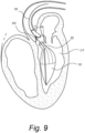
- Fig. 1 shows an exemplary embodiment of a heart support device for providing circulatory assistance to a patient.
- the heart support device is positioned within the left ventricle LV.
- the heart support device according to the invention comprises a chamber 10 defining an internal volume and having at least one aperture 12 for fluid communication between the internal volume of the chamber 10 and a volume external to the chamber 10.
- the chamber 10 is dimensioned so that the chamber 10 and the aperture 12 are disposed within a chamber of the human heart (in this case, the left ventricle LV).
- the device may have a maximum outer diameter of between 2cm and 6cm, more particularly 2cm and 4cm.
- the chamber has a maximum outer diameter at its widest point of 2.5cm.
- the length of the device (extending from the aperture to the end opposing the aperture) can be between 4cm and 10cm, more particularly between 5cm and 8cm. In one embodiment, the device has a length of 5cm.
- the length of device can be adjusted to individual patient needs. For example, for many patients in need of circulatory assistance, the heart wall may be compromised to some degree, leading to a significant increase in the internal volume of the left ventricle compared to healthy individuals. Mapping can be carried out for individual patients can devices for according to individual needs. Alternatively, a range of sizes (small, medium, large) can be made and the appropriate size selected for each individual.
- the support device further comprises at least one dynamic volume body 14, configured to be inflated and/or deflated to alternately increase and decrease the available interior volume of the chamber 10 (i.e. the volume within the chamber 10 that can be filled with blood).
- a catheter 16 comprising at least one fluid lumen 18 is in fluid communication with the dynamic volume body 14 and is configured to deliver fluid (e.g. a liquid, or a gas such as Helium) to the dynamic volume body 14 to inflate and/or deflate the body 14.
- a directional flow structure 20 is further provided to direct a flow of blood out of the chamber 10 in a direction substantially aligned with a direction in which the catheter extends.
- the directional flow structure 20 advantageously directs the displaced blood in a direction of the aortic valve, i.e. in a manner that more closely approximates the natural function of the heart.
- the flow of blood created by the device more closely mimics the blood flow seen during uncompromised natural heart function, thereby improving the efficiency of the supported heart.
- the directional flow structure 20 can comprise a restricted opening at the proximal end of the chamber 10 (e,g, a neck).
- the proximal end of the chamber 10 is the end from which the catheter 16 extends.
- the restricted opening 22 has a smaller cross-sectional area than the cross-sectional area of the chamber 10 and provides a constriction at the first opening.
- the restricted opening 22 has a diameter that is less than (or equal to) the diameter of the aorta (generally 30% or less of the diameter of the main body; in some examples between 0.3cm and 2cm, more particularly between 0.3cm and 1.5cm, more particularly 0.5cm).
- the restricted opening 22 is centred on the catheter 16 and comprises a straight sided tube or conduit.
- the tube can be cylindrical (with parallel walls) or tapered towards the opening.
- a venturi tube forms the restricted opening, as described in more detail below.
- Directional flow can also be provided by a structure that provides a pumping impulse in the direction of the aortic valve.
- Embodiments of the present invention comprising different directional flow structures will be described in more detail below.
- the heart support device can further comprise a support structure 24 configured to support the chamber 10 in an expanded configuration.
- the support structure 24 can hold the chamber 10 in a stable position such that a balloon or other inflatable member can be inflated within the chamber 10 to decrease the available volume (thus forcing blood through the directional flow structure).
- the support structure 24 can be collapsible. This can allow the device to be advanced into the left ventricle through the aorta (or another natural lumen).
- the support structure can be biased into an expanded position and maintained in the collapsed position during insertion by way of a guide tube or other tool.
- the support structure 24 can comprise a shape memory material, e.g. in the form of a collapsible scaffold formed of nitinol or another shape memory material.
- the support structure 24 can return to its expanded configuration.
- the support structure 24 can comprise an expandable scaffold that can be expanded with a supply of fluid or gas to the scaffold.
- the support structure 24 is inflatable.
- the support structure 24 can be provided in fluid communication with at least one lumen of the catheter 16 to allow the support structure 24 to be inflated after it has been advanced into the heart lumen.
- the dynamic volume body can act as a displacement body which is disposed within the chamber, and is expandable to fill an increasing proportion of the internal volume of chamber 10. Because the displacement body (e.g. the balloon 26) is disposed within the chamber, as the balloon inflates, it displaces blood within the chamber, thus forcing it through the aperture 12 towards the aortic valve.
- the displacement body e.g. the balloon 26
- the support structure 24 can comprise a scaffold formed of a resilient material, which is biased into and expandable from a first configuration in which the chamber body 10 has a first internal volume to a second configuration in which the chamber body 10 comprises a second internal volume, which is larger than the first internal volume.
- the resilient material can comprise an elastic or shape-memory material that is biased into an expanded configuration and can be compressed or collapsed whilst the device it advanced through a natural lumen into the heart chamber.
- the dynamic volume body 14 can be configured to expand the support structure 24 from the first configuration to the second configuration, thereby increasing the internal volume of the chamber 10.
- the dynamic volume body 12 can comprise an inflatable balloon 26 disposed within the chamber 10.
- the balloon 26 is disposed within the chamber body 10, which can take the form of a cup 28.
- the cup 28 is relatively rigid compared to the balloon 26, once it has been expanded to its expanded configuration.
- the balloon 26 is formed at least partially of a membrane defining an interior volume that is configured to expand upon an increase of fluid (e.g. liquid or gas) within the balloon 28.
- the membrane can be formed of an elastic material configured to stretch as the interior volume is filled with air, or the membrane can be substantially non-elastic.
- the cup 28 can be formed of an expandable scaffold 30 with sidewall(s) 32, which defines the volume of the chamber 10.
- the sidewalls of the cup can be formed in the manner described in WO2016/001218 A1 , which is hereby incorporated by reference in its entirety. However, in light of the present disclosure, the skilled person will appreciate that other cup constructions are possible.
- Figs. 2B-2D illustrate the configuration of a 'balloon-in-cup' type of heart support device at different stages.
- the cup 28 is in its expanded configuration within the heart lumen.
- the balloon 26 is empty and the interior volume of the chamber 10 is filled with blood B.
- the balloon 26 is inflated by filling the balloon 26 with gas or liquid. As the balloon 26 inflates, the volume it occupies within the chamber 10 increases, and blood B is displaced from the interior volume of the chamber 10 and forced through the aperture 12 at the proximal end of the chamber. As shown in Fig.
- this causes blood to leave the chamber 10 via the aperture and the directional flow structure, thus direction the flow of blood towards the aortic valve AV.
- the balloon 26 inflates, it occupies an increasing volume within the cup 28, thus displacing the blood filling the chamber 10 and forcing it from the chamber 10 through the directional flow structure and the aperture 12 towards the aortic valve AV.
- the balloon 26 can be configured in number of different ways.
- the balloon 26 can comprise a balloon 26 that is free to expand in all directions (in the manner of a conventional balloon). As the balloon inflated within the chamber body 10, the available internal volume of the chamber decreases and blood is forced from the chamber 10 through the aperture 12.
- the balloon 26 can comprise a flexible elastic membrane secured within the cup 28 to form a sealed cavity that can be filled with inflating fluid.
- the cup and membrane combination of embodiment can be formed in a similar manner to the device described in WO2016/001218 A1 , except that the walls of the cup that forms the chamber body 10 should extend beyond the membrane towards the restricted opening that provides the directional flow control.
- the balloon 26 is provided at the opposite end of the chamber body 10 to the first opening 12.
- the cup 28 can incorporate a distal portion of the catheter 16 with a plurality of fluid ports 27 into its sidewall.
- the openings 27 are provided in fluid communication with the interior of the balloon 26 and are configured to fill the sealed cavity of the balloon 26.
- the balloon can be inflated and deflated by a catheter that is not incorporated into the sidewall.
- the balloon 26 can comprise a toroidal (or donut shaped) balloon 26.
- the toroidal balloon 26 can be configured to be centrally filled from a plurality of openings 27 in the catheter 16. This can provide symmetrical filling of the toroidal balloon 26.
- the chamber 10 can extend from a proximal end at which the first aperture 22 is located to a distal end, opposite the proximal end.
- the balloon 28 is disposed at the distal end of the chamber 10 and is configured to expand proximally.
- the balloon 28 is configured such that the flexible membrane expands (upon filling) in a direction towards the direction in which the catheter 16 extends.
- the extension of the flexible membrane in this direction can be configured to cause an impulse to further assist in directional flow control of blood leaving the chamber 10 through the aperture 12.
- the balloon 28 (or balloons) can be configured to inflate asymmetrically, expanding from the distal end toward the proximal end of the chamber 10.
- the chamber 10 can be further provided with additional openings, disposed at the distal end of the chamber 10, remote from the first openings.
- the additional openings 30 provide additional fluid communication between the interior volume of the chamber 10 and the volume exterior to the chamber 10.
- the additional openings 30 allow blood from the lower part of the chamber 10 to be flushed through the additional openings 30 as the available volume of the chamber 10 decreases.
- the risk of clots forming within the chamber 10 is decreased.
- the flow of blood through the additional openings 30 flushes blood from the area A between the device and the heart wall, further reducing the risk of clots forming in the LV.
- the additional opening(s) 30 should be smaller than the first opening(s) 12, so that a majority of the blood expelled from the chamber 10 is expelled through the first opening(s) 12 towards the aorta.
- the additional opening(s) 30 account for less than 30% of the cross-sectional flow area into/out of the chamber 10, whilst the first opening(s) 12 account for 70% or more.
- the additional opening(s) 30 account for approximately 5%-10% (e.g. 5%) of the cross-sectional flow area into/out of the chamber 10, whilst the first opening(s) 12 account for approximately 90-95% (e.g. 95%).
- this ratio can be modified to suit the particular application/specific patient needs.
- the chamber 10 can comprise one or more additional side openings 32 configured to provide an additional inlet for blood into the interior of the chamber 10.
- the additional side openings 32 can comprise one-way valve structures configured to allow the flow of fluid into the chamber 10 via the openings 32 (and prevent flow in the opposite direction).
- the heart support device can draw blood into the chamber 10 as the available volume increases from a location within the heart lumen that is remote from the aortic valve. This may prevent undesirable negative pressure behind the aortic valve.
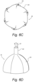
- the additional side openings 32 can be configured to be self-sealing as the pressure within the chamber 10 increases with the decreasing available volume. As shown in Fig. 6A-6D , the additional side openings 32 can be formed at the intersection of a plurality of overlapping panels 34. The panels 34 are arranged in a circular overlapping arrangement, with the leading edge 34a of each panel 34 overlapping the trailing edge 34b of the next panel 34. As shown in Figs. 6A and 6B , as the available interior volume of the chamber 10 increases, the pressure within the chamber 10 drops and blood is drawn in through the openings 32 between the panels 34.
- the pressure within the chamber 10 forces the overlapping portions of the panels 34 into contact with each other, thus sealing the openings 32 shut (see Fig. 6C ).
- the blood within the chamber 10 is thus forced out of the chamber 10 through the opening 12, as shown in Fig. 6D .
- the panels 34 can be supported by a plurality of ribs that provide support structure 24.
- the additional openings 32 can comprise conventional one-way valves.
- the additional openings can be configured as one-way flow opening(s) 32 that allow flow into the interior volume of the chamber 10 and prevent or inhibit flow out of the chamber 10.
- the directional flow structure 20 comprises a vortex inducing arrangement.
- the vortex inducing structure can comprise a plurality of static blades 36 arranged within the restricted opening 22 (e.g. a static impeller arrangement) configured to induce a vortex in the fluid that flows over the blades.
- a vortex or spiral flow towards the aorta can be induced by the manner in which the balloon 26 expands.
- the balloon 26 can be wrapped or folded within the chamber such that upon expansion is twists to produce a vortex if flow through the aperture.
- the support device comprises a chamber 10 formed by a series of panels 34 supported by a support structure 24.
- the support structure 24 comprises a plurality of ribs 36 that are arranged in a helical fashion, extending from a first common end point 38 and, advantageously, meeting at a second common end point 40 (for example, as shown in Fig. 8 ).
- the support structure 24 is configured to be collapsed and expanded (during insertion of the device) by twisting the walls of the chamber 10 relative to the axis defined between the common end points 38, 40.
- the relative rotation of the walls of the chamber about the axis can be between 45 degree and 90 degrees, although other rotations are possible.
- the directional flow structure can be configured as a venturi tube.
- the venturi tube can comprise a restricted opening at the exit of the chamber body 10 that comprises an entry cone, a constriction, and an exit cone.
- the entry cone can comprise a cone of approximately 30 degrees, whilst the exit cone can comprise a cone of approximately 5 degrees.
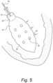
- the restricted opening 22 can be angled with respect to the chamber body 10.
- the chamber body 10 can comprise a longitudinal axis A
- the restricted opening 22 can comprise a tube that extends along a second axis B, which is not coaxial with the first axis A.
- the angle ⁇ between the restricted opening 22 and the longitudinal axis of the chamber body 10 can be between 20 and 50 degrees, more particularly approximately 35 degrees. This angle allows the chamber body 10 to lie against the wall the left ventricle without obstructing the mitral valve MV, whilst still directing the flow of blood from the chamber 10 directly towards the aortic valve AV.
- a method of providing circulatory assistance comprises the steps of placing the device 10 with a chamber of the heart such that the aperture of the device and associated directional flow components are disposed within the heart chamber, on a chamber side of the aortic valve. Once placed, the method comprises alternately inflating and deflating the dynamic volume body to displace blood within the chamber such that it is expelled through the aperture in a direction of the aortic valve.
- the present invention has been described with reference to exemplary embodiments designed for use in the left ventricle.
- the invention behind the present disclosure can be applied to other chambers of the heart.
- a heart support device according to the present invention can be optimised for use within the right ventricle, and the directional flow structure can direct the flow of blood out of the chamber 10 towards the pulmonary valve.
- the features of the one embodiment described herein can be combined with the features of one or more additional embodiments.
- other modifications can be made to the exemplary embodiments without departing from the scope of the invention which is defined by the following claims.
Landscapes
- Health & Medical Sciences (AREA)
- Heart & Thoracic Surgery (AREA)
- Engineering & Computer Science (AREA)
- Cardiology (AREA)
- Life Sciences & Earth Sciences (AREA)
- Anesthesiology (AREA)
- Biomedical Technology (AREA)
- Hematology (AREA)
- Mechanical Engineering (AREA)
- Animal Behavior & Ethology (AREA)
- General Health & Medical Sciences (AREA)
- Public Health (AREA)
- Veterinary Medicine (AREA)
- Vascular Medicine (AREA)
- Physics & Mathematics (AREA)
- Geometry (AREA)
- External Artificial Organs (AREA)
Claims (15)
- Eine Herzunterstützungsvorrichtung zur Kreislaufassistenz, wobei die Herzunterstützungsvorrichtung Folgendes aufweist:einen Kammerkörper (10), der eine Kammer mit einem Innenvolumen definiert, das so konfiguriert ist, dass es mit Blut gefüllt werden kann, wobei der Kammerkörper (10) eine erste Öffnung (12) aufweist, wobei der Kammerkörper (10) und die erste Öffnung (12) so dimensioniert sind, dass sie innerhalb einer Kammer des menschlichen Herzens angeordnet werden können;einen dynamischen Volumenkörper (14), der so konfiguriert ist, dass er aufgeblasen oder entleert werden kann, um das Innenvolumen der Kammer abwechselnd zu vergrößern oder zu verkleinern;einen Katheter (16), der mindestens ein Lumen in Fluidverbindung mit dem dynamischen Volumenkörper (14) aufweist und der so konfiguriert ist, dass er Fluid an den dynamischen Volumenkörper abgibt, um den dynamischen Volumenkörper aufzublasen; undeine gerichtete Strömungsstruktur, die so konfiguriert ist, dass sie einen Blutstrom aus der Kammer heraus in eine Richtung leitet, die im Wesentlichen mit einer Richtung ausgerichtet ist, in die sich der Katheter (16) erstreckt;wobei die Vorrichtung ferner eine einen Wirbel induzierende Anordnung aufweist.
- Die Herzunterstützungsvorrichtung nach Anspruch 1, wobei die gerichtete Strömungsstruktur eine verengte Öffnung (22) aufweist, die eine Verengung an der ersten Öffnung (12) bereitstellt.
- Die Herzunterstützungsvorrichtung nach Anspruch 1 oder 2, die ferner eine Stützstruktur (24) aufweist, die so konfiguriert ist, dass sie den Kammerkörper (10) in einer expandierten Konfiguration stützt.
- Die Herzunterstützungsvorrichtung nach Anspruch 3, wobei die Stützstruktur (24) kollabierbar ist.
- Die Herzunterstützungsvorrichtung nach Anspruch 3 oder 4, wobei die Stützstruktur (24) aufblasbar ist und wobei sie in Fluidverbindung mit mindestens einem Lumen des Katheters (16) steht, um ein Aufblasen der Stützstruktur (24) zu ermöglichen.
- Die Herzunterstützungsvorrichtung nach einem der Ansprüche 3 bis 5, wobei die Stützstruktur (24) ein aus einem elastischen Material gebildetes Gerüst aufweist, das in eine zweite Konfiguration vorgespannt ist, und das von einer ersten Konfiguration, in der der Kammerkörper (10) ein erstes Innenvolumen aufweist, in die zweite Konfiguration ausdehnbar ist, in der der Kammerkörper (10) ein zweites Innenvolumen aufweist, wobei das zweite Innenvolumen größer als das erste Innenvolumen ist.
- Die Herzunterstützungsvorrichtung nach Anspruch 6, wobei der dynamische Volumenkörper (14) so konfiguriert ist, dass er die Stützstruktur (24) von der ersten Konfiguration in die zweite Konfiguration ausdehnt, wodurch das Innenvolumen der Kammer (10) vergrößert wird.
- Die Herzunterstützungsvorrichtung nach einem der Ansprüche 1 bis 5, wobei der dynamische Volumenkörper (14) einen aufblasbaren Ballon (26) aufweist, der innerhalb der Kammer angeordnet ist.
- Die Herzunterstützungsvorrichtung nach Anspruch 8, wobei sich der Kammerkörper (10) von einem proximalen Ende, an dem sich die erste Öffnung (12) befindet, zu einem distalen Ende erstreckt, das dem proximalen Ende gegenüberliegt, wobei der Ballon (26) am distalen Ende des Kammerkörpers (10) angeordnet und so konfiguriert ist, dass er sich proximal ausdehnt.
- Die Herzunterstützungsvorrichtung nach einem der Ansprüche 1 bis 9, wobei der Kammerkörper (10) ferner mit einer oder mehreren zusätzlichen Öffnungen (30) versehen ist, die am distalen Ende der Kammer (10) entfernt von der ersten Öffnung angeordnet sind.
- Die Herzunterstützungsvorrichtung nach einem der Ansprüche 1 bis 10, wobei der Kammerkörper (10) eine oder mehrere zusätzliche Seitenöffnungen (32) aufweisen kann, die so konfiguriert sind, dass sie einen zusätzlichen Einlass für Blut in das Innere der Kammer (10) bereitstellen.
- Die Herzunterstützungsvorrichtung nach einem der Ansprüche 2 bis 11, wobei die Wirbel induzierende Anordnung eine Vielzahl von statischen Flügelblättern (36) aufweist, die innerhalb der verengten Öffnung (22) angeordnet sind.
- Die Herzunterstützungsvorrichtung nach einem der vorhergehenden Ansprüche, wobei der Kammerkörper (10) eine schraubenförmige Stützstruktur (40) aufweist, die so konfiguriert ist, dass sie ein schraubenförmiges Kollabieren des Kammerkörpers (10) ermöglicht.
- Die Herzunterstützungsvorrichtung nach einem der vorhergehenden Ansprüche, wobei die gerichtete Strömungsstruktur ein Venturi-Rohr aufweist.
- Die Herzunterstützungsvorrichtung nach einem der Ansprüche 2 bis 14, wobei der Kammerkörper (10) eine Längsachse (A) aufweist und wobei die verengte Öffnung (22) ein Rohr aufweist, das sich entlang einer zweiten Achse (B) erstreckt, und wobei die erste Achse und die zweite Achse nicht koaxial sind.
Priority Applications (1)
| Application Number | Priority Date | Filing Date | Title |
|---|---|---|---|
| EP24208088.5A EP4470597A3 (de) | 2018-07-27 | 2019-07-26 | Herzunterstützungsvorrichtung mit gerichteter flusshilfe |
Applications Claiming Priority (2)
| Application Number | Priority Date | Filing Date | Title |
|---|---|---|---|
| NL2021401A NL2021401B1 (en) | 2018-07-27 | 2018-07-27 | Heart support device with directional flow assist |
| PCT/NL2019/050499 WO2020022905A1 (en) | 2018-07-27 | 2019-07-26 | Heart support device with directional flow assist |
Related Child Applications (2)
| Application Number | Title | Priority Date | Filing Date |
|---|---|---|---|
| EP24208088.5A Division EP4470597A3 (de) | 2018-07-27 | 2019-07-26 | Herzunterstützungsvorrichtung mit gerichteter flusshilfe |
| EP24208088.5A Division-Into EP4470597A3 (de) | 2018-07-27 | 2019-07-26 | Herzunterstützungsvorrichtung mit gerichteter flusshilfe |
Publications (2)
| Publication Number | Publication Date |
|---|---|
| EP3829670A1 EP3829670A1 (de) | 2021-06-09 |
| EP3829670B1 true EP3829670B1 (de) | 2025-03-26 |
Family
ID=63684398
Family Applications (2)
| Application Number | Title | Priority Date | Filing Date |
|---|---|---|---|
| EP24208088.5A Pending EP4470597A3 (de) | 2018-07-27 | 2019-07-26 | Herzunterstützungsvorrichtung mit gerichteter flusshilfe |
| EP19756005.5A Active EP3829670B1 (de) | 2018-07-27 | 2019-07-26 | Herzunterstützungsvorrichtung mit gerichteter flusshilfe |
Family Applications Before (1)
| Application Number | Title | Priority Date | Filing Date |
|---|---|---|---|
| EP24208088.5A Pending EP4470597A3 (de) | 2018-07-27 | 2019-07-26 | Herzunterstützungsvorrichtung mit gerichteter flusshilfe |
Country Status (5)
| Country | Link |
|---|---|
| US (2) | US11400274B2 (de) |
| EP (2) | EP4470597A3 (de) |
| CN (2) | CN118949259A (de) |
| NL (1) | NL2021401B1 (de) |
| WO (1) | WO2020022905A1 (de) |
Families Citing this family (8)
| Publication number | Priority date | Publication date | Assignee | Title |
|---|---|---|---|---|
| NL2022660B1 (en) | 2019-03-01 | 2020-09-15 | Stichting Katholieke Univ | Heart Assist Device |
| US20210178037A1 (en) * | 2019-12-16 | 2021-06-17 | Medtronic, Inc. | Intra-ventricular pulsatile assist system (iv-pas) |
| US20210393943A1 (en) * | 2020-06-17 | 2021-12-23 | Kamran Najmabadi | Reconfigurable fluid displacement apparatuses and methods of use |
| NL2026671B1 (en) * | 2020-10-14 | 2022-06-08 | Cardiacbooster B V | Cardiac assist device |
| NL2028130B1 (en) * | 2021-05-03 | 2022-11-10 | Cardiacbooster B V | Cardiac assist device with high frequency operation |
| EP4504327A1 (de) * | 2022-04-07 | 2025-02-12 | CardiacBooster BV | Einlassventile für eine herzunterstützungsvorrichtung und zugehörige technologie |
| EP4611875A1 (de) * | 2022-11-02 | 2025-09-10 | CardiacBooster BV | Herzunterstützungsvorrichtungen, -systeme und -verfahren |
| WO2025217070A1 (en) * | 2024-04-08 | 2025-10-16 | Edwards Lifesciences Corporation | Cardiac support pumps |
Citations (1)
| Publication number | Priority date | Publication date | Assignee | Title |
|---|---|---|---|---|
| WO2017205909A1 (en) * | 2016-06-01 | 2017-12-07 | Peter Ayre | Ventricle assist device |
Family Cites Families (19)
| Publication number | Priority date | Publication date | Assignee | Title |
|---|---|---|---|---|
| US4964864A (en) * | 1988-09-27 | 1990-10-23 | American Biomed, Inc. | Heart assist pump |
| ES2020787A6 (es) * | 1990-07-20 | 1991-09-16 | Figuera Aymerich Diego | Bomba intra-ventricular expansible de asistencia circulatoria. |
| US5827171A (en) * | 1996-10-31 | 1998-10-27 | Momentum Medical, Inc. | Intravascular circulatory assist device |
| US5820542A (en) * | 1996-10-31 | 1998-10-13 | Momentum Medical, Inc. | Modified circulatory assist device |
| JP2003000700A (ja) * | 2001-06-21 | 2003-01-07 | Motoaki Hoshino | Iabpシステムのバルーンを用いた循環補助方法及び装置並びに血流制御弁 |
| AU2002952691A0 (en) * | 2002-11-15 | 2002-11-28 | Sunshine Heart Company Pty Ltd | Heart assist device utilising aortic deformation |
| CN1239209C (zh) * | 2003-09-09 | 2006-02-01 | 张杰民 | 磁驱动的轴流式心脏辅助泵 |
| CN1946449A (zh) * | 2004-02-26 | 2007-04-11 | V-卡迪亚控股有限公司 | 分离心脏循环 |
| US7172551B2 (en) * | 2004-04-12 | 2007-02-06 | Scimed Life Systems, Inc. | Cyclical pressure coronary assist pump |
| GB0428257D0 (en) * | 2004-12-23 | 2005-01-26 | Harefield Cardiac Ltd | A blood circulation assistance device |
| CN101472627B (zh) * | 2006-01-30 | 2013-05-08 | 国立成功大学 | 双元脉动双心室辅助装置 |
| JP2009530041A (ja) * | 2006-03-23 | 2009-08-27 | ザ・ペン・ステート・リサーチ・ファンデーション | 拡張可能なインペラポンプを有する心臓補助装置 |
| US8784292B2 (en) | 2006-04-24 | 2014-07-22 | Yoel Ovil | Double balloon pump cardiac assist device and related method of use |
| US8579788B2 (en) * | 2010-03-08 | 2013-11-12 | Wilmo Orejola | Auto-regulated R-wave synchronized intraventricular balloon pump heart assist device |
| GB201005198D0 (en) * | 2010-03-26 | 2010-05-12 | Univ Aston | Pulsatile blood pump |
| DE102013208038B4 (de) * | 2013-05-02 | 2016-09-08 | Michael Siegenthaler | Katheterbasierendes Herzunterstützungssystem |
| US10098992B2 (en) | 2014-06-30 | 2018-10-16 | Stichting Katholieke Universiteit | Heart support device |
| DE102017103350B4 (de) * | 2016-02-19 | 2023-05-25 | Hermann Lauboeck | Herzfunktionssystem mit einer Kunstherzvorrichtung mit redundanten Blut-Strömungspfaden sowie Verfahren zum Unterstützen der Herzfunktion |
| EP3398626B1 (de) * | 2017-05-04 | 2021-02-24 | Abiomed Europe GmbH | Intravaskuläre blutpumpe mit ballon |
-
2018
- 2018-07-27 NL NL2021401A patent/NL2021401B1/en active
-
2019
- 2019-07-26 CN CN202410918627.9A patent/CN118949259A/zh active Pending
- 2019-07-26 CN CN201980049894.4A patent/CN112512623B/zh active Active
- 2019-07-26 EP EP24208088.5A patent/EP4470597A3/de active Pending
- 2019-07-26 US US17/263,554 patent/US11400274B2/en active Active
- 2019-07-26 WO PCT/NL2019/050499 patent/WO2020022905A1/en not_active Ceased
- 2019-07-26 EP EP19756005.5A patent/EP3829670B1/de active Active
-
2022
- 2022-07-19 US US17/813,523 patent/US20220347460A1/en active Pending
Patent Citations (1)
| Publication number | Priority date | Publication date | Assignee | Title |
|---|---|---|---|---|
| WO2017205909A1 (en) * | 2016-06-01 | 2017-12-07 | Peter Ayre | Ventricle assist device |
Also Published As
| Publication number | Publication date |
|---|---|
| US11400274B2 (en) | 2022-08-02 |
| EP3829670A1 (de) | 2021-06-09 |
| NL2021401B1 (en) | 2020-01-31 |
| WO2020022905A1 (en) | 2020-01-30 |
| CN112512623A (zh) | 2021-03-16 |
| EP4470597A3 (de) | 2025-03-05 |
| EP4470597A2 (de) | 2024-12-04 |
| US20220347460A1 (en) | 2022-11-03 |
| US20210244935A1 (en) | 2021-08-12 |
| CN112512623B (zh) | 2024-07-30 |
| CN118949259A (zh) | 2024-11-15 |
Similar Documents
| Publication | Publication Date | Title |
|---|---|---|
| US20220347460A1 (en) | Heart support device with directional flow assist | |
| JP7707345B2 (ja) | 血液ポンプ及びリングシール | |
| US20240350795A1 (en) | Intra-aortic balloon apparatus, assist devices and methods for improving flow, counterpulsation and haemodynamics | |
| NL2022661B1 (en) | Collapsible device for circulatory assistance | |
| US20230248961A1 (en) | Cardiac assist device | |
| US20260027343A1 (en) | Heart assist device | |
| US20110172690A1 (en) | Balloon Catheter for Use with a Surgical Coring System | |
| HK40092583A (en) | Intra-aortic balloon apparatus, assist devices, for improving flow, counterpulsation, and haemodynamics | |
| HK40092583B (en) | Intra-aortic balloon apparatus, assist devices, for improving flow, counterpulsation, and haemodynamics | |
| HK40007055B (en) | Intra-aortic balloon apparatus, assist devices, and methods for improving flow, counterpulsation, and haemodynamics | |
| HK40007055A (en) | Intra-aortic balloon apparatus, assist devices, and methods for improving flow, counterpulsation, and haemodynamics |
Legal Events
| Date | Code | Title | Description |
|---|---|---|---|
| STAA | Information on the status of an ep patent application or granted ep patent |
Free format text: STATUS: UNKNOWN |
|
| STAA | Information on the status of an ep patent application or granted ep patent |
Free format text: STATUS: THE INTERNATIONAL PUBLICATION HAS BEEN MADE |
|
| PUAI | Public reference made under article 153(3) epc to a published international application that has entered the european phase |
Free format text: ORIGINAL CODE: 0009012 |
|
| STAA | Information on the status of an ep patent application or granted ep patent |
Free format text: STATUS: REQUEST FOR EXAMINATION WAS MADE |
|
| 17P | Request for examination filed |
Effective date: 20210215 |
|
| AK | Designated contracting states |
Kind code of ref document: A1 Designated state(s): AL AT BE BG CH CY CZ DE DK EE ES FI FR GB GR HR HU IE IS IT LI LT LU LV MC MK MT NL NO PL PT RO RS SE SI SK SM TR |
|
| RAP1 | Party data changed (applicant data changed or rights of an application transferred) |
Owner name: STICHTING RADBOUD UNIVERSITAIR MEDISCH CENTRUM |
|
| DAV | Request for validation of the european patent (deleted) | ||
| DAX | Request for extension of the european patent (deleted) | ||
| RAP1 | Party data changed (applicant data changed or rights of an application transferred) |
Owner name: CARDIACBOOSTER BV |
|
| RAP3 | Party data changed (applicant data changed or rights of an application transferred) |
Owner name: CARDIACBOOSTER BV |
|
| RAP3 | Party data changed (applicant data changed or rights of an application transferred) |
Owner name: CARDIACBOOSTER BV |
|
| RAP3 | Party data changed (applicant data changed or rights of an application transferred) |
Owner name: CARDIACBOOSTER BV |
|
| REG | Reference to a national code |
Ref country code: DE Ref legal event code: R079 Free format text: PREVIOUS MAIN CLASS: A61M0001100000 Ipc: A61M0060268000 Ref country code: DE Ref legal event code: R079 Ref document number: 602019067793 Country of ref document: DE Free format text: PREVIOUS MAIN CLASS: A61M0001100000 Ipc: A61M0060268000 |
|
| GRAP | Despatch of communication of intention to grant a patent |
Free format text: ORIGINAL CODE: EPIDOSNIGR1 |
|
| STAA | Information on the status of an ep patent application or granted ep patent |
Free format text: STATUS: GRANT OF PATENT IS INTENDED |
|
| RIC1 | Information provided on ipc code assigned before grant |
Ipc: A61M 60/17 20210101ALI20240507BHEP Ipc: A61M 60/843 20210101ALI20240507BHEP Ipc: A61M 60/295 20210101ALI20240507BHEP Ipc: A61M 60/268 20210101AFI20240507BHEP |
|
| INTG | Intention to grant announced |
Effective date: 20240605 |
|
| GRAJ | Information related to disapproval of communication of intention to grant by the applicant or resumption of examination proceedings by the epo deleted |
Free format text: ORIGINAL CODE: EPIDOSDIGR1 |
|
| STAA | Information on the status of an ep patent application or granted ep patent |
Free format text: STATUS: REQUEST FOR EXAMINATION WAS MADE |
|
| GRAP | Despatch of communication of intention to grant a patent |
Free format text: ORIGINAL CODE: EPIDOSNIGR1 |
|
| STAA | Information on the status of an ep patent application or granted ep patent |
Free format text: STATUS: GRANT OF PATENT IS INTENDED |
|
| INTC | Intention to grant announced (deleted) | ||
| INTG | Intention to grant announced |
Effective date: 20241023 |
|
| GRAS | Grant fee paid |
Free format text: ORIGINAL CODE: EPIDOSNIGR3 |
|
| GRAA | (expected) grant |
Free format text: ORIGINAL CODE: 0009210 |
|
| STAA | Information on the status of an ep patent application or granted ep patent |
Free format text: STATUS: THE PATENT HAS BEEN GRANTED |
|
| AK | Designated contracting states |
Kind code of ref document: B1 Designated state(s): AL AT BE BG CH CY CZ DE DK EE ES FI FR GB GR HR HU IE IS IT LI LT LU LV MC MK MT NL NO PL PT RO RS SE SI SK SM TR |
|
| REG | Reference to a national code |
Ref country code: GB Ref legal event code: FG4D |
|
| REG | Reference to a national code |
Ref country code: CH Ref legal event code: EP |
|
| REG | Reference to a national code |
Ref country code: DE Ref legal event code: R096 Ref document number: 602019067793 Country of ref document: DE |
|
| REG | Reference to a national code |
Ref country code: IE Ref legal event code: FG4D |
|
| P01 | Opt-out of the competence of the unified patent court (upc) registered |
Free format text: CASE NUMBER: APP_14214/2025 Effective date: 20250324 |
|
| REG | Reference to a national code |
Ref country code: NL Ref legal event code: FP |
|
| PG25 | Lapsed in a contracting state [announced via postgrant information from national office to epo] |
Ref country code: RS Free format text: LAPSE BECAUSE OF FAILURE TO SUBMIT A TRANSLATION OF THE DESCRIPTION OR TO PAY THE FEE WITHIN THE PRESCRIBED TIME-LIMIT Effective date: 20250626 |
|
| PG25 | Lapsed in a contracting state [announced via postgrant information from national office to epo] |
Ref country code: FI Free format text: LAPSE BECAUSE OF FAILURE TO SUBMIT A TRANSLATION OF THE DESCRIPTION OR TO PAY THE FEE WITHIN THE PRESCRIBED TIME-LIMIT Effective date: 20250326 |
|
| PGFP | Annual fee paid to national office [announced via postgrant information from national office to epo] |
Ref country code: GB Payment date: 20250604 Year of fee payment: 7 |
|
| REG | Reference to a national code |
Ref country code: LT Ref legal event code: MG9D |
|
| PG25 | Lapsed in a contracting state [announced via postgrant information from national office to epo] |
Ref country code: NO Free format text: LAPSE BECAUSE OF FAILURE TO SUBMIT A TRANSLATION OF THE DESCRIPTION OR TO PAY THE FEE WITHIN THE PRESCRIBED TIME-LIMIT Effective date: 20250626 |
|
| PGFP | Annual fee paid to national office [announced via postgrant information from national office to epo] |
Ref country code: NL Payment date: 20250602 Year of fee payment: 7 |
|
| PG25 | Lapsed in a contracting state [announced via postgrant information from national office to epo] |
Ref country code: HR Free format text: LAPSE BECAUSE OF FAILURE TO SUBMIT A TRANSLATION OF THE DESCRIPTION OR TO PAY THE FEE WITHIN THE PRESCRIBED TIME-LIMIT Effective date: 20250326 |
|
| PG25 | Lapsed in a contracting state [announced via postgrant information from national office to epo] |
Ref country code: LV Free format text: LAPSE BECAUSE OF FAILURE TO SUBMIT A TRANSLATION OF THE DESCRIPTION OR TO PAY THE FEE WITHIN THE PRESCRIBED TIME-LIMIT Effective date: 20250326 |
|
| PGFP | Annual fee paid to national office [announced via postgrant information from national office to epo] |
Ref country code: FR Payment date: 20250603 Year of fee payment: 7 |
|
| PG25 | Lapsed in a contracting state [announced via postgrant information from national office to epo] |
Ref country code: BG Free format text: LAPSE BECAUSE OF FAILURE TO SUBMIT A TRANSLATION OF THE DESCRIPTION OR TO PAY THE FEE WITHIN THE PRESCRIBED TIME-LIMIT Effective date: 20250326 Ref country code: GR Free format text: LAPSE BECAUSE OF FAILURE TO SUBMIT A TRANSLATION OF THE DESCRIPTION OR TO PAY THE FEE WITHIN THE PRESCRIBED TIME-LIMIT Effective date: 20250627 |
|
| PGFP | Annual fee paid to national office [announced via postgrant information from national office to epo] |
Ref country code: IE Payment date: 20250610 Year of fee payment: 7 |
|
| PG25 | Lapsed in a contracting state [announced via postgrant information from national office to epo] |
Ref country code: SE Free format text: LAPSE BECAUSE OF FAILURE TO SUBMIT A TRANSLATION OF THE DESCRIPTION OR TO PAY THE FEE WITHIN THE PRESCRIBED TIME-LIMIT Effective date: 20250326 |
|
| REG | Reference to a national code |
Ref country code: AT Ref legal event code: MK05 Ref document number: 1778460 Country of ref document: AT Kind code of ref document: T Effective date: 20250326 |
|
| PG25 | Lapsed in a contracting state [announced via postgrant information from national office to epo] |
Ref country code: SM Free format text: LAPSE BECAUSE OF FAILURE TO SUBMIT A TRANSLATION OF THE DESCRIPTION OR TO PAY THE FEE WITHIN THE PRESCRIBED TIME-LIMIT Effective date: 20250326 |
|
| PG25 | Lapsed in a contracting state [announced via postgrant information from national office to epo] |
Ref country code: PT Free format text: LAPSE BECAUSE OF FAILURE TO SUBMIT A TRANSLATION OF THE DESCRIPTION OR TO PAY THE FEE WITHIN THE PRESCRIBED TIME-LIMIT Effective date: 20250728 Ref country code: ES Free format text: LAPSE BECAUSE OF FAILURE TO SUBMIT A TRANSLATION OF THE DESCRIPTION OR TO PAY THE FEE WITHIN THE PRESCRIBED TIME-LIMIT Effective date: 20250326 |
|
| PGFP | Annual fee paid to national office [announced via postgrant information from national office to epo] |
Ref country code: DE Payment date: 20250603 Year of fee payment: 7 |
|
| PG25 | Lapsed in a contracting state [announced via postgrant information from national office to epo] |
Ref country code: IT Free format text: LAPSE BECAUSE OF FAILURE TO SUBMIT A TRANSLATION OF THE DESCRIPTION OR TO PAY THE FEE WITHIN THE PRESCRIBED TIME-LIMIT Effective date: 20250326 Ref country code: PL Free format text: LAPSE BECAUSE OF FAILURE TO SUBMIT A TRANSLATION OF THE DESCRIPTION OR TO PAY THE FEE WITHIN THE PRESCRIBED TIME-LIMIT Effective date: 20250326 |
|
| PG25 | Lapsed in a contracting state [announced via postgrant information from national office to epo] |
Ref country code: AT Free format text: LAPSE BECAUSE OF FAILURE TO SUBMIT A TRANSLATION OF THE DESCRIPTION OR TO PAY THE FEE WITHIN THE PRESCRIBED TIME-LIMIT Effective date: 20250326 |
|
| PG25 | Lapsed in a contracting state [announced via postgrant information from national office to epo] |
Ref country code: EE Free format text: LAPSE BECAUSE OF FAILURE TO SUBMIT A TRANSLATION OF THE DESCRIPTION OR TO PAY THE FEE WITHIN THE PRESCRIBED TIME-LIMIT Effective date: 20250326 |
|
| PG25 | Lapsed in a contracting state [announced via postgrant information from national office to epo] |
Ref country code: RO Free format text: LAPSE BECAUSE OF FAILURE TO SUBMIT A TRANSLATION OF THE DESCRIPTION OR TO PAY THE FEE WITHIN THE PRESCRIBED TIME-LIMIT Effective date: 20250326 |
|
| PG25 | Lapsed in a contracting state [announced via postgrant information from national office to epo] |
Ref country code: SK Free format text: LAPSE BECAUSE OF FAILURE TO SUBMIT A TRANSLATION OF THE DESCRIPTION OR TO PAY THE FEE WITHIN THE PRESCRIBED TIME-LIMIT Effective date: 20250326 |
|
| PG25 | Lapsed in a contracting state [announced via postgrant information from national office to epo] |
Ref country code: IS Free format text: LAPSE BECAUSE OF FAILURE TO SUBMIT A TRANSLATION OF THE DESCRIPTION OR TO PAY THE FEE WITHIN THE PRESCRIBED TIME-LIMIT Effective date: 20250726 |
|
| REG | Reference to a national code |
Ref country code: DE Ref legal event code: R097 Ref document number: 602019067793 Country of ref document: DE |
|
| PG25 | Lapsed in a contracting state [announced via postgrant information from national office to epo] |
Ref country code: DK Free format text: LAPSE BECAUSE OF FAILURE TO SUBMIT A TRANSLATION OF THE DESCRIPTION OR TO PAY THE FEE WITHIN THE PRESCRIBED TIME-LIMIT Effective date: 20250326 |
|
| REG | Reference to a national code |
Ref country code: NL Ref legal event code: RC Free format text: DETAILS LICENCE OR PLEDGE: RIGHT OF PLEDGE, ESTABLISHED Name of requester: DE STAAT DER NEDERLANDEN (MINISTERIE EZK/RVO/INNOVATIEKREDIET) Effective date: 20260106 |
|
| PG25 | Lapsed in a contracting state [announced via postgrant information from national office to epo] |
Ref country code: CZ Free format text: LAPSE BECAUSE OF FAILURE TO SUBMIT A TRANSLATION OF THE DESCRIPTION OR TO PAY THE FEE WITHIN THE PRESCRIBED TIME-LIMIT Effective date: 20250326 |
|
| PLBE | No opposition filed within time limit |
Free format text: ORIGINAL CODE: 0009261 |
|
| STAA | Information on the status of an ep patent application or granted ep patent |
Free format text: STATUS: NO OPPOSITION FILED WITHIN TIME LIMIT |
|
| REG | Reference to a national code |
Ref country code: CH Ref legal event code: L10 Free format text: ST27 STATUS EVENT CODE: U-0-0-L10-L00 (AS PROVIDED BY THE NATIONAL OFFICE) Effective date: 20260211 |
|
| REG | Reference to a national code |
Ref country code: CH Ref legal event code: H13 Free format text: ST27 STATUS EVENT CODE: U-0-0-H10-H13 (AS PROVIDED BY THE NATIONAL OFFICE) Effective date: 20260224 |
|
| 26N | No opposition filed |
Effective date: 20260105 |
|
| PG25 | Lapsed in a contracting state [announced via postgrant information from national office to epo] |
Ref country code: LU Free format text: LAPSE BECAUSE OF NON-PAYMENT OF DUE FEES Effective date: 20250726 |
|
| REG | Reference to a national code |
Ref country code: BE Ref legal event code: MM Effective date: 20250731 |
|
| PG25 | Lapsed in a contracting state [announced via postgrant information from national office to epo] |
Ref country code: BE Free format text: LAPSE BECAUSE OF NON-PAYMENT OF DUE FEES Effective date: 20250731 |
|
| PG25 | Lapsed in a contracting state [announced via postgrant information from national office to epo] |
Ref country code: CH Free format text: LAPSE BECAUSE OF NON-PAYMENT OF DUE FEES Effective date: 20250731 |