EP3829418B1 - Ratio métal/surface de microaiguille - Google Patents
Ratio métal/surface de microaiguille Download PDFInfo
- Publication number
- EP3829418B1 EP3829418B1 EP19745648.6A EP19745648A EP3829418B1 EP 3829418 B1 EP3829418 B1 EP 3829418B1 EP 19745648 A EP19745648 A EP 19745648A EP 3829418 B1 EP3829418 B1 EP 3829418B1
- Authority
- EP
- European Patent Office
- Prior art keywords
- base
- metal coating
- sensor
- tip
- capsule
- Prior art date
- Legal status (The legal status is an assumption and is not a legal conclusion. Google has not performed a legal analysis and makes no representation as to the accuracy of the status listed.)
- Active
Links
Images

Classifications
-
- A—HUMAN NECESSITIES
- A61—MEDICAL OR VETERINARY SCIENCE; HYGIENE
- A61B—DIAGNOSIS; SURGERY; IDENTIFICATION
- A61B5/00—Measuring for diagnostic purposes; Identification of persons
- A61B5/145—Measuring characteristics of blood in vivo, e.g. gas concentration or pH-value ; Measuring characteristics of body fluids or tissues, e.g. interstitial fluid or cerebral tissue
- A61B5/14507—Measuring characteristics of blood in vivo, e.g. gas concentration or pH-value ; Measuring characteristics of body fluids or tissues, e.g. interstitial fluid or cerebral tissue specially adapted for measuring characteristics of body fluids other than blood
- A61B5/1451—Measuring characteristics of blood in vivo, e.g. gas concentration or pH-value ; Measuring characteristics of body fluids or tissues, e.g. interstitial fluid or cerebral tissue specially adapted for measuring characteristics of body fluids other than blood for interstitial fluid
- A61B5/14514—Measuring characteristics of blood in vivo, e.g. gas concentration or pH-value ; Measuring characteristics of body fluids or tissues, e.g. interstitial fluid or cerebral tissue specially adapted for measuring characteristics of body fluids other than blood for interstitial fluid using means for aiding extraction of interstitial fluid, e.g. microneedles or suction
-
- A—HUMAN NECESSITIES
- A61—MEDICAL OR VETERINARY SCIENCE; HYGIENE
- A61B—DIAGNOSIS; SURGERY; IDENTIFICATION
- A61B5/00—Measuring for diagnostic purposes; Identification of persons
- A61B5/145—Measuring characteristics of blood in vivo, e.g. gas concentration or pH-value ; Measuring characteristics of body fluids or tissues, e.g. interstitial fluid or cerebral tissue
- A61B5/14532—Measuring characteristics of blood in vivo, e.g. gas concentration or pH-value ; Measuring characteristics of body fluids or tissues, e.g. interstitial fluid or cerebral tissue for measuring glucose, e.g. by tissue impedance measurement
-
- A—HUMAN NECESSITIES
- A61—MEDICAL OR VETERINARY SCIENCE; HYGIENE
- A61B—DIAGNOSIS; SURGERY; IDENTIFICATION
- A61B5/00—Measuring for diagnostic purposes; Identification of persons
- A61B5/68—Arrangements of detecting, measuring or recording means, e.g. sensors, in relation to patient
- A61B5/6846—Arrangements of detecting, measuring or recording means, e.g. sensors, in relation to patient specially adapted to be brought in contact with an internal body part, i.e. invasive
- A61B5/6847—Arrangements of detecting, measuring or recording means, e.g. sensors, in relation to patient specially adapted to be brought in contact with an internal body part, i.e. invasive mounted on an invasive device
- A61B5/685—Microneedles
-
- A—HUMAN NECESSITIES
- A61—MEDICAL OR VETERINARY SCIENCE; HYGIENE
- A61B—DIAGNOSIS; SURGERY; IDENTIFICATION
- A61B2505/00—Evaluating, monitoring or diagnosing in the context of a particular type of medical care
- A61B2505/07—Home care
-
- A—HUMAN NECESSITIES
- A61—MEDICAL OR VETERINARY SCIENCE; HYGIENE
- A61B—DIAGNOSIS; SURGERY; IDENTIFICATION
- A61B2560/00—Constructional details of operational features of apparatus; Accessories for medical measuring apparatus
- A61B2560/04—Constructional details of apparatus
- A61B2560/0443—Modular apparatus
-
- A—HUMAN NECESSITIES
- A61—MEDICAL OR VETERINARY SCIENCE; HYGIENE
- A61B—DIAGNOSIS; SURGERY; IDENTIFICATION
- A61B5/00—Measuring for diagnostic purposes; Identification of persons
- A61B5/68—Arrangements of detecting, measuring or recording means, e.g. sensors, in relation to patient
- A61B5/6801—Arrangements of detecting, measuring or recording means, e.g. sensors, in relation to patient specially adapted to be attached to or worn on the body surface
- A61B5/6802—Sensor mounted on worn items
- A61B5/681—Wristwatch-type devices
-
- A—HUMAN NECESSITIES
- A61—MEDICAL OR VETERINARY SCIENCE; HYGIENE
- A61B—DIAGNOSIS; SURGERY; IDENTIFICATION
- A61B5/00—Measuring for diagnostic purposes; Identification of persons
- A61B5/68—Arrangements of detecting, measuring or recording means, e.g. sensors, in relation to patient
- A61B5/6801—Arrangements of detecting, measuring or recording means, e.g. sensors, in relation to patient specially adapted to be attached to or worn on the body surface
- A61B5/6813—Specially adapted to be attached to a specific body part
- A61B5/6824—Arm or wrist
-
- A—HUMAN NECESSITIES
- A61—MEDICAL OR VETERINARY SCIENCE; HYGIENE
- A61B—DIAGNOSIS; SURGERY; IDENTIFICATION
- A61B5/00—Measuring for diagnostic purposes; Identification of persons
- A61B5/68—Arrangements of detecting, measuring or recording means, e.g. sensors, in relation to patient
- A61B5/6801—Arrangements of detecting, measuring or recording means, e.g. sensors, in relation to patient specially adapted to be attached to or worn on the body surface
- A61B5/683—Means for maintaining contact with the body
- A61B5/6831—Straps, bands or harnesses
-
- A—HUMAN NECESSITIES
- A61—MEDICAL OR VETERINARY SCIENCE; HYGIENE
- A61B—DIAGNOSIS; SURGERY; IDENTIFICATION
- A61B5/00—Measuring for diagnostic purposes; Identification of persons
- A61B5/68—Arrangements of detecting, measuring or recording means, e.g. sensors, in relation to patient
- A61B5/6801—Arrangements of detecting, measuring or recording means, e.g. sensors, in relation to patient specially adapted to be attached to or worn on the body surface
- A61B5/683—Means for maintaining contact with the body
- A61B5/6832—Means for maintaining contact with the body using adhesives
-
- A—HUMAN NECESSITIES
- A61—MEDICAL OR VETERINARY SCIENCE; HYGIENE
- A61B—DIAGNOSIS; SURGERY; IDENTIFICATION
- A61B5/00—Measuring for diagnostic purposes; Identification of persons
- A61B5/68—Arrangements of detecting, measuring or recording means, e.g. sensors, in relation to patient
- A61B5/6801—Arrangements of detecting, measuring or recording means, e.g. sensors, in relation to patient specially adapted to be attached to or worn on the body surface
- A61B5/683—Means for maintaining contact with the body
- A61B5/6839—Anchoring means, e.g. barbs
-
- A—HUMAN NECESSITIES
- A61—MEDICAL OR VETERINARY SCIENCE; HYGIENE
- A61B—DIAGNOSIS; SURGERY; IDENTIFICATION
- A61B5/00—Measuring for diagnostic purposes; Identification of persons
- A61B5/68—Arrangements of detecting, measuring or recording means, e.g. sensors, in relation to patient
- A61B5/6846—Arrangements of detecting, measuring or recording means, e.g. sensors, in relation to patient specially adapted to be brought in contact with an internal body part, i.e. invasive
- A61B5/6879—Means for maintaining contact with the body
- A61B5/688—Means for maintaining contact with the body using adhesives
-
- A—HUMAN NECESSITIES
- A61—MEDICAL OR VETERINARY SCIENCE; HYGIENE
- A61B—DIAGNOSIS; SURGERY; IDENTIFICATION
- A61B5/00—Measuring for diagnostic purposes; Identification of persons
- A61B5/68—Arrangements of detecting, measuring or recording means, e.g. sensors, in relation to patient
- A61B5/6846—Arrangements of detecting, measuring or recording means, e.g. sensors, in relation to patient specially adapted to be brought in contact with an internal body part, i.e. invasive
- A61B5/6879—Means for maintaining contact with the body
- A61B5/6882—Anchoring means
Definitions
- the present invention relates to a device for body monitoring via analysis of body fluid, typically interstitial, using microneedles.
- the present invention relates to the management of sweat present on the skin where the microneedles are positioned.
- Some pathologies such as diabetes require daily monitoring of biochemical parameters of the human body, i.e. concentrations of certain compounds (blood sugar in the example of glucose).
- interstitial fluid that is, the fluid that fills the space between the blood capillaries and the cells. It has an ionic composition close to that of blood plasma.
- microneedles are held on the skin with an adhesive strip.
- One example is the GlucoWatch device, which used iontophoresis (and not needles).
- interferences related to sweat present on the skin may be interferences related to sweat present on the skin. These interferences also depend on the thickness of the epidermis, which varies between individuals: the thickness of the skin to reach the interstitial fluid is then not the same.
- the invention aims to address these difficulties.
- the invention provides a sensor for measuring analytes present in a bodily fluid in a living being according to claim 1.
- the height of the base is greater than 200 ⁇ m and preferably greater than 300 ⁇ m.
- the senor comprises a plurality of groups comprising at least one microneedle as defined above, a group defining a working electrode, a group defining a reference electrode, and preferably a counter-electrode, or even a neutral electrode.
- the microneedles of the two groups are spaced apart by at least 1 mm (to avoid pollution by the production of hydrogen peroxide).
- the height of the tip is between 200 and 700 ⁇ m, preferably between 300 and 500 ⁇ m.
- the base has a pyramid shape.
- the base has a pyramidal shape, with a width greater than 140 ⁇ m.
- the substrate is polymer or silicon, or not metal.
- the biochemical element completely covers the metal coating of the tip and partially covers the metal coating of the base.
- the biochemical element partially covers the metal coating of the tip.
- system further comprises a patch attachable to the capsule, the patch having adhesive power to the skin.
- a sensor for measuring analytes present in a bodily fluid of a living being (typically the interstitial fluid) will be described.
- This sensor is inserted into a body monitoring system 1 which will be described later.
- the sensor comprises a substrate and at least one microneedle 210, preferably a plurality of sets of microneedles 210.
- microneedles 210 is meant a preferably full needle (because no need to take liquid), with a total height between 100 ⁇ m and 1000 ⁇ m, preferably 300 ⁇ m and 800 ⁇ m. Each of these advantageous characteristics of the microneedles 210 can be taken separately or in combination with the others.
- the microneedle 210 comprises a base 210a, integral with the substrate 242 and which extends therefrom in a main direction Z.
- the microneedle 210 further comprises a tip 210b, integral with the base 210a, which also extends in the main direction Z.
- the 210b tip is fully covered with a metal coating.
- the base 210a is partially covered with a metal coating, preferably in the form of a track 210c from the substrate 242 to the metal coating of the tip 210b.
- the metal coating may be, as a variant, a metal coating arranged directly below the metal coating of the tip.
- the microneedle may mainly comprise silicon. In the case of silicon, the microneedles have an external non-conductive protective SiO 2 layer, formed by oxidation of the silicon on the surface. Thus, the microneedle may not comprise an additional coating to the SiO 2 layer, such a coating being used in the prior art to electrically insulate the base of the microneedle.
- a biochemical element which is capable of reacting with the analyte (to allow measurements relating to this analyte) at least partially covers the metal coating.
- the entire metal coating of the tip 210b is covered with the biochemical element and the metal coating of the base 210a is not covered.
- the base 210a may be in contact with sweat from the skin via piercing the skin.
- the biochemical element can be deposited on the metal coating of the base 210a, preferably of the track 210c.
- the surface density of biochemical elements deposited on the track 210c depends on the chemical affinity between the element biochemical and the surface of the base 210a. It can be different for example if the track 210c is made of metal while the rest of the surface is made of silicon.
- Biochemical elements can be deposited evenly on track 210c.
- the chemistry and/or adsorption capabilities of the biochemical elements can be controlled such that the biochemical elements are deposited only on the metal coating and not on the substrate 242, thereby saving the amount of chemical elements used in the manufacture of the electrodes.
- the metal surface of the base can be a metal surface arranged directly under the metal surface of the tip, but not covered by biochemical elements.
- the biochemical elements are adapted to interact with any conductive material and therefore with track 210C.
- the substrate 242 is made of polymer or silicon, or any other non-metallic material.
- the base 210a and the tip 210b (before metal coating) can be made of the same material as the substrate.
- the metal also functions to transmit the electrical signals generated by the biochemical element when it reacts with the analyte.
- the proposed solution is to limit the presence of the biochemical elements adapted to interact with the track 210c on the base 210a, which means that it is necessary to limit the presence of the metal coating on the base.
- the surface ratio of the metal coating of the base 210a on the total surface of the base 210a is between 1 and 20%. This means that the metal coating in the form of track 210c of the base 210a represents between 1 and 20% of the surface of the base 210a. If the surface ratio of the metal coating of the base 210a on the total surface of the base 210a is greater than 20%, the electrical noise caused by the presence of sweat can make the measurement insignificant.
- the value of 1% is related to the fact that the presence of metal coating on the base 210a is necessary for the transmission of signals and the value of 20% is related to the fact of limiting the risk of having biochemical element on the base 210a of the microneedle 210.
- the ratio is between 1% and 15%.
- the base 210a has a dimension along the main direction Z (called height) greater than 200 ⁇ m, and preferably 300 ⁇ m. This value is linked to the thickness of the epidermis, which is generally between 80 and 180 ⁇ m before accessing the interstitial fluid (depending on the type of skin). With 200 ⁇ m, the probability that the tip 210b is well bathed in interstitial fluid is greatly increased.
- the tip 210b for its part, has a dimension in the main direction (called height) between 200 and 700 ⁇ m and preferably between 300 and 500 ⁇ m.
- the microneedle 210 has a minimum height of 340 ⁇ m and a maximum height approximately equal to 1000 ⁇ m.
- the height of the tip 210b and the height of the base 210c are chosen to ensure on the one hand that the tip is in good contact with the interstitial fluid and on the other hand that the hypodermis (where the mechanical nerves and a greater density of blood vessels are located) is not reached.
- the sensor typically comprises several groups of microneedles 210 verifying the preceding characteristics. More specifically, each group of microneedles 210 comprises at least one functionalized microneedle 210, i.e. intended for the same function. A distinction is thus generally made between a group forming a working electrode, a group forming a reference electrode, and possibly a group forming a counter-electrode and sometimes a group forming a neutral electrode (which is distinguished in material from the reference electrode).
- the microneedles 210 advantageously consist of a network of microneedles 210 in contact with the skin when the capsule 220 is placed on a person's body.
- the groups are spaced at least 1 mm apart, or even 2 mm or 3 mm. This means that the distance between two microneedles 210 of two respective groups is greater than or equal to 1 mm, or even 2 mm or 3 mm.
- the sensor presented is advantageously mounted on a capsule 220 which can be coupled to a housing 120 to form a body monitoring system.
- the present invention relates to an electronic body monitoring system 1. It is an improvement of the device of the document WO2018104647 . Therefore, the invention fits into the same general concept of an integral, autonomous, low-pain, low-hygienic-risk and reusable system.
- Body monitoring means checking the biochemical constants of a person carrying system 1, typically the concentration of a protein, a hormone, a marker, oxygen, nutrients, etc., in the person's interstitial fluid.
- a person carrying system typically the concentration of a protein, a hormone, a marker, oxygen, nutrients, etc.
- An example is blood sugar.
- the person skilled in the art may monitor, if necessary, other physical body quantities such as lactate, hydration, etc.
- interstitial fluid The description will be illustrated with interstitial fluid but applies to other body fluids such as blood.
- System 1 is said to be autonomous, because it does not require the use of additional hardware.
- System 1 is intended to be attached to a limb of a living being, typically an arm or leg of a human being.
- the preferred attachment area is the wrist where System 1 is similar to a watch.
- System 1 is formed of two modules 100, 200 connected together by a separable link 300 which is reusable.
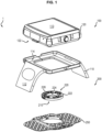
- the first module 100 comprises in particular means for attaching and tightening 110 (which may comprise a bracelet or strap 112 and a receptacle 114) the system 1 to a member and the second module 200 comprises a capsule 220 which integrates the sensor described above (FIG. 3).
- the microneedles 210 of the sensor when the first module 100 is in position on the member, make it possible to analyze a body fluid, as mentioned above.
- the microneedles 210 advantageously consist of an array of microneedles 210 in contact with the skin when the first module 100 is placed on a person's body.
- said microneedles 210 comprise between four and fifty microneedles, substantially pyramidal.
- the two modules 100 and 200 each have a coupling face 122, 222, of complementary shape, which makes it possible to place the second module 200 in a reception location of the first module 100.
- first module 100 and the second module 200 are configured to be coupled by a separable link 300.
- This link 300 secures the two modules 100, 200.
- the first module 100 further comprises a housing 120 in which are arranged data processing means (in particular a processor or a microcontroller) configured to process measurements acquired by the sensor, and where appropriate data storage means.
- data in particular a memory, in particular of the flash type, and/or the memory of the microcontroller
- the data processing means are also used to generate instructions to different components. In the context of this description, these different functions are provided by the same unit. However, it is possible to provide dedicated processors.
- the system also comprises a battery for the electrical power supply of the components, advantageously rechargeable, for example via a port (which it is understood can also be used to connect the system 1 for example to a computer to download the acquired and/or processed data).
- the system 1 can comprise wireless connection means (in particular of the WiFi type, but also Bluetooth, or even 3G/4G) for connection to a network, in particular the Internet, and a user interface such as a screen, possibly touch-sensitive, to display the monitoring results to the user.
- wireless connection means in particular of the WiFi type, but also Bluetooth, or even 3G/4G
- a network in particular the Internet
- a user interface such as a screen, possibly touch-sensitive
- the housing 120 further comprises electrical connectors, on its coupling face 122 with the coupling face 222 capsule 220.
- the capsule 220 of the second module has a closed box shape, typically sealed, which can be coupled with the housing 120 100.
- This capsule 220 is interchangeable, which makes it possible to obtain an economical and efficient system, where only the so-called consumable parts must be changed.
- the capsule 220 can have an annular shape, with a through opening 224 in the center.
- the capsule 220 comprises electrical connectors 226, on a coupling face 222 with the housing 120, which can cooperate with the electrical connectors of the housing 120. If there is transmission of fluid from the second module to the first then additional fluidic connectors are provided on the capsule 220 and the box 120.
- the second module 200 comprises a patch 250, removably secured to the capsule 220.
- the second module (capsule 220 and patch 250) forms an interchangeable assembly of the system which is chosen according to the type of monitoring required and depending on the state of deterioration of the microneedles 210 and/or the sensor.
- the capsule 220 contains the microneedles 210 and/or the sensor, changing the capsule 220 makes it possible to change sensors if they are at the end of their life or if it is desired to change the physical quantity measured, in a simple, rapid and safe manipulation, without having to throw away other parts (in particular the first module).
- the 220 capsule minimizes the amount of expensive components and/or materials (advanced electronic equipment such as a battery or wireless communication means), it is relatively inexpensive.
Landscapes
- Health & Medical Sciences (AREA)
- Life Sciences & Earth Sciences (AREA)
- Physics & Mathematics (AREA)
- Medical Informatics (AREA)
- Surgery (AREA)
- Engineering & Computer Science (AREA)
- Biomedical Technology (AREA)
- Heart & Thoracic Surgery (AREA)
- Biophysics (AREA)
- Molecular Biology (AREA)
- Pathology (AREA)
- Animal Behavior & Ethology (AREA)
- General Health & Medical Sciences (AREA)
- Public Health (AREA)
- Veterinary Medicine (AREA)
- Optics & Photonics (AREA)
- Emergency Medicine (AREA)
- Measurement Of The Respiration, Hearing Ability, Form, And Blood Characteristics Of Living Organisms (AREA)
Description
- La présente invention concerne un dispositif de surveillance corporelle via analyse de liquide corporel, typiquement interstitiel, à l'aide de microaiguilles.
- Plus précisément, la présente invention concerne la gestion de la sueur présente sur la peau là où sont positionnées les microaiguilles.
- Certaines pathologies comme le diabète nécessitent une surveillance quotidienne de paramètres biochimiques du corps humain, i.e. des concentrations en certains composés (la glycémie dans l'exemple du glucose).
- Pour cela, il est courant de piquer un point de la peau de sorte à faire perler une goutte de sang, et d'analyser cette goutte soit de façon réactive (par exemple avec une bandelette), soit de façon électronique (par exemple par au moins d'un capteur analytique), de façon à estimer le ou les paramètres cible.
- On connait aujourd'hui des systèmes évolués bien moins invasifs qui se contentent d'analyser le liquide interstitiel, c'est-à-dire le fluide qui remplit l'espace entre les capillaires sanguins et les cellules. Il a en effet une composition ionique proche de celle du plasma sanguin.
- Ces systèmes évolués permettent ainsi de surveiller les paramètres biochimiques souhaités de façon transcutanée, c'est-à-dire sans nécessité de percer régulièrement la peau et de prélever.
- On connait des dispositifs avec microaiguilles, qui ont l'avantage d'être moins invasive que des aiguilles classiques. Toutefois, il est important que ces microaiguilles restent en place.
- Il existe pour cela des dispositifs à demeure, où des microaiguilles sont maintenues sur la peau avec une bande adhésive. Toutefois, on souhaite pouvoir effectuer un contrôle en continu ou quasi-continu, ce qui requiert des dispositifs autonomes. On pourra citer le dispositif GlucoWatch, qui utilisait l'iontophorèse (et non pas des aiguilles).
- Toutefois, lorsqu'un tel dispositif comporte des microaiguilles, il peut exister des interférences liées à la sueur présente sur la peau. Ces interférences dépendent en outre de l'épaisseur de l'épiderme, qui est variable selon les individus : l'épaisseur de peau pour atteindre le liquide interstitiel n'est alors pas la même.
- Pour résoudre cela, il existe des solutions visant à masquer certaines parties des microaiguilles, pour éviter qu'elles n'interfèrent. On peut citer un revêtement isolant, comme dans le document
US 2014/0275897 par exemple. Toutefois, ces produits multicouches sont coûteux à réaliser et difficile à produire. - L'invention vise à adresser ces difficultés.
- Pour pallier à certaines de ces difficultés, l'invention propose un capteur pour mesurer des analytes présentes dans un fluide corporel dans un être vivant selon la revendication 1.
- Dans un mode de réalisation, la hauteur de la base est supérieure à 200µm et préférentiellement supérieur à 300 µm.
- Dans un mode de réalisation, le capteur comprend une pluralité de groupes comprenant au moins une microaiguille telle que définie précédemment un groupe définissant une électrode de travail, un groupe définissant une électrode de référence, et préférablement une contre-électrode, voire une électrode neutre.
- Dans un mode de réalisation, les microaiguilles des deux groupes sont écartées entre elles d'au moins 1 mm (pour éviter la pollution par fabrication de peroxyde d'hydrogène).
- Dans un mode de réalisation, la hauteur de la pointe est comprise entre 200 et 700 µm, préférablement entre 300 et 500 µm.
- Dans un mode de réalisation, la base a une forme pyramidale.
- Dans un mode de réalisation, la base a une forme pyramidale, avec une largeur supérieure à 140 µm.
- Dans un mode de réalisation, le substrat est en polymère ou silicium, ou pas en métal.
- Dans un mode de réalisation, l'élément biochimique recouvre intégralement le revêtement métallique de la pointe et partiellement le revêtement métallique de la base.
- Dans un mode de réalisation, l'élément biochimique recouvre partiellement le revêtement métallique de la pointe.
- L'invention propose aussi un système de surveillance corporelle destiné à être attaché à un membre d'un être vivant, comprenant :
- un boitier, comprenant une face de couplage,
- une capsule comprenant un capteur tel que décrit précédemment, la capsule pouvant s'engager de façon amovible avec la face de couplage du boitier.
- Dans un mode de réalisation, le système comprend en outre un patch attachable à la capsule, le patch ayant un pouvoir adhésif à la peau.
- D'autres caractéristiques et avantages de la présente invention apparaîtront à la lecture de la description qui va suivre d'un mode de réalisation préférentiel. Cette description sera donnée en référence aux dessins annexés dans lesquels :
- La
figure 1 illustre en vue éclatée un bracelet/lanière, un boitier, une capsule et un patch tel qu'utilisable dans le cadre de l'invention, - La
figure 2 illustre une vue illustrative de plusieurs microaiguilles différentes, sans respect des proportions ou des angles. - En relation avec les
figures 1 et2 , un capteur pour mesurer des analytes présentes dans un fluide corporel d'un être vivant (typiquement le liquide interstitiel) va être décrit. Ce capteur s'insère dans un système de surveillance corporelle 1 qui sera décrit par la suite. - Le capteur comprend un substrat et au moins une microaiguille 210, préférablement un plusieurs ensembles de microaiguilles 210.
- Par microaiguilles 210, on entend une aiguille préférablement pleine (car pas besoin de prélever de liquide), d'une hauteur totale comprise entre 100µm et 1000µm, préférablement 300µm et 800µm. Chacune de ces caractéristiques avantageuses des microaiguilles 210 peut être prise séparément ou en combinaison avec les autres.
- La micro-aiguille 210 comprend une base 210a, solidaire du substrat 242 et qui s'en étend selon une direction principale Z. La microaiguille 210 comprend en outre une pointe 210b, solidaire de la base 210a, qui s'étend aussi selon la direction principale Z. Visuellement, il peut y avoir un changement de pente entre la base 210a et la pointe 210b. On a donc substrat 242, puis base 210a, puis pointe 210b.
- La pointe 210b est entièrement recouverte d'un revêtement métallique.
- La base 210a est partiellement recouverte d'un revêtement métallique, préférentiellement sous forme de piste 210c depuis le substrat 242 jusqu'au revêtement métallique de la pointe 210b. Le revêtement métallique peut être, en variante, un revêtement métallique agencé directement en-dessous du revêtement métallique de la pointe. La micro-aiguille peut comprendre majoritairement du silicium. Dans le cas du silicium, les micro-aiguilles présentent une couche externe de SiO2 de protection non conductive, formée par oxydation du silicium en surface. Ainsi, la micro-aiguille peut ne pas comprendre de revêtement additionnel à la couche de SiO2, un tel revêtement étant utilisé dans l'art antérieur pour isoler électriquement la base de la micro-aiguille.
- Enfin, un élément biochimique, qui est apte à réagir avec l'analyte (pour permettre des mesures relatives à cet analyte) recouvre au moins partiellement le revêtement métallique. Préférablement, l'intégralité du revêtement métallique de la pointe 210b est recouverte de l'élément biochimique et le revêtement métallique de la base 210a n'est pas recouverte. Toutefois, à cause des procédés de fabrication, il se peut qu'une partie du revêtement métallique de la base 210a soit aussi recouvert de l'élément biochimique. Or, la base 210a peut être au contact de la sueur de la peau via le percement de la peau.
- Dans les procédés utilisés, l'élément biochimique peut se déposer sur le revêtement métallique de la base 210a, préférentiellement de la piste 210c. La densité surfacique d'éléments biochimiques déposés sur la piste 210c dépend de l'affinité chimique entre l'élément biochimique et la surface de la base 210a. Elle peut être par exemple différente si la piste 210c est en métal tandis que le reste de la surface est en silicium.
- Les éléments biochimiques peuvent être déposés uniformément sur la piste 210c.
- En variante, la chimie et/ou les capacités d'adsorption des éléments biochimiques peuvent être contrôlés de manière à ce que les éléments biochimiques se déposent uniquement sur le revêtement métallique et non pas sur le substrat 242, ce qui permet d'économiser la quantité d'éléments chimiques utilisés lors de la fabrication des électrodes.
- Dans le cas où des éléments biochimiques recouvrent uniquement la pointe 210b, on considère que la surface métallique de la base peut être une surface métallique agencée directement sous la surface métallique de la pointe, mais non recouverte par des éléments biochimiques.
- Les éléments biochimiques sont adaptés à interagir avec toute matière conductive et donc avec la piste 210C.
- Le substrat 242 est en polymère ou en silicium, voire tout autre matériau non-métallique. La base 210a et la pointe 210b (avant revêtement métallique) peuvent être réalisées dans le même matériau que le substrat.
- Le métal a aussi pour fonction de transmettre les signaux électriques générés par l'élément biochimique lorsqu'il réagit avec l'analyte.
- Afin de limiter l'influence de la sueur, la solution proposée est de limiter la présence de l'éléments biochimiques adaptés à interagir avec la piste 210c sur la base 210a, ce qui signifie qu'il faut limiter la présence du revêtement métallique sur la base. Pour cela, le ratio de surface du revêtement métallique de la base 210a sur la surface totale du la base 210a est compris entre 1 et 20%. Cela signifie que le revêtement métallique sous forme de piste 210c de la base 210a représente entre 1 et 20% de la surface de la base 210a. Si le ratio de surface du revêtement métallique de la base 210a sur la surface totale du la base 210a est supérieur à 20%, le bruit électrique entraîné par la présence de sueur peut rendre la mesure non significative.
- La valeur de 1% est lié au fait que la présence de revêtement métallique sur la base 210a est nécessaire pour la transmission des signaux et la valeur de 20% est liée au fait de limiter le risque d'avoir de l'élément biochimique sur la base 210a de la microaiguille 210.
- Préférablement, le ratio est compris entre 1% et 15%.
- Par « surface », on entend la surface exposée à l'environnement externe.
- La base 210a a une dimension selon la direction principale Z (appelée hauteur) supérieure à 200 µm, et préférentiellement à 300 µm. Cette valeur est liée à l'épaisseur de l'épiderme, qui est généralement comprise entre 80 et 180µm avant d'accéder au liquide interstitiel (selon le type de peau). Avec 200µm, on augmente fortement la probabilité que la pointe 210b soit bien baignée de liquide interstitiel.
- La pointe 210b, quant à elle, a une dimension selon la direction principale (appelée hauteur) comprise entre 200 et 700 µm et préférablement comprise entre 300 et 500 µm.
- Au total, selon les modes de réalisation, la microaiguille 210 a une hauteur minimale de 340µm et une hauteur maximale environ égale à 1000µm. La hauteur de la pointe 210b et la hauteur de la base 210c sont choisies pour s'assurer d'une part que la pointe soit bien au contact du liquide interstitiel et d'autre part que l'hypoderme (où se trouve les nerfs mécaniques et une plus grande densité de vaisseau sanguin) ne soit pas atteint.
- Le capteur comprend typiquement plusieurs groupes de microaiguilles 210 vérifiant les caractéristiques précédentes. Plus spécifiquement, chaque groupe de microaiguilles 210 comprend au moins une microaiguille 210 fonctionnalisée, c'est-à-dire destinée à une même fonction. On distingue ainsi généralement un groupe formant une électrode de travail, un groupe formant une électrode de référence, et éventuellement un groupe formant une contre-électrode et parfois un groupe formant une électrode neutre (qui se distingue en matériau de l'électrode de référence).
- Les microaiguilles 210 consistent avantageusement en un réseau de microaiguilles 210 au contact de la peau lorsque la capsule 220 est placée sur le corps d'une personne.
- Afin d'éviter les contaminations chimiques entre différents groupes de microaiguilles 210, notamment par fabrication de peroxyde d'hydrogène lors de la réaction biochimique entre la microaiguille et l'analyte, les groupes sont espacées d'au moins 1mm, voire 2mm ou 3 mm. Cela signifie que la distance entre deux microaiguilles 210 de deux groupes respectifs est supérieure ou égale à 1mm, voire 2mm ou 3 mm.
- Le capteur présenté est avantageusement monté sur une capsule 220 qui peut se coupler à un boitier 120 pour former un système de surveillance corporelle.
- La fin de la description vise à présenter cela.
- En référence à la
figure 1 , la présente invention concerne un système électronique 1 de surveillance corporelle. Il s'agit d'une amélioration du dispositif du documentWO2018104647 . Par conséquent, l'invention se place dans le même concept général de système intégral autonome à faible douleur, faible risque hygiénique et réutilisable. - Par surveillance corporelle, on entend la vérification de constantes biochimiques d'une personne porteuse du système 1, typiquement la concentration en une protéine, une hormone, un marqueur, en oxygène, en nutriments, etc., dans le liquide interstitiel de la personne. On citera l'exemple de la glycémie. L'homme du métier pourra surveiller si besoin d'autres grandeurs physiques corporelles telles que le lactate, l'hydratation, etc.
- La description sera illustrée avec du liquide interstitiel mais s'applique aux autres liquides corporels tels que le sang.
- Le système 1 est dit autonome, car il ne nécessite pas l'utilisation de matériel supplémentaire.
- Le système 1 est destiné à être attaché à un membre d'un être vivant, typiquement un bras ou une jambe d'un être humain. La zone d'attache privilégiée est le poignet où le système 1 s'apparente à une montre.
- Le système 1 est formé de deux modules 100, 200 reliées entre eux par une liaison séparable 300 qui est réutilisable.
- Le premier module 100 comprend notamment des moyens d'attache et de serrage 110 (qui peut comprendre un bracelet ou une lanière 112 et un réceptacle 114) du système 1 à un membre et le deuxième module 200 comprend une capsule 220 qui intègre le capteur décrit précédemment (figure 3). Les microaiguilles 210 du capteur, lorsque le premier module 100 est en position sur le membre, permettent d'analyser un fluide corporel, comme mentionné précédemment.
- Comme mentionné précédemment, les microaiguilles 210 consistent avantageusement en un réseau de microaiguilles 210 au contact de la peau lorsque le premier module 100 est placé sur le corps d'une personne.
- De façon préférée, lesdits microaiguilles 210 comprennent entre quatre et cinquante microaiguilles, sensiblement pyramidales.
- Les deux modules 100 et 200 présentent chacun une face de couplage 122, 222, de forme complémentaire, qui permet de placer le deuxième module 200 dans un emplacement d'accueil du premier module 100
- Enfin, le premier module 100 et le deuxième module 200 sont configurés pour être couplés par une liaison séparable 300. Cette liaison 300 solidarise les deux modules 100, 200.
- Comme illustré sur la
figure 1 , le premier module 100 comprend en outre un boitier 120 dans lequel sont disposés des moyens de traitement de données (en particulier un processeur ou un microcontrôleur) configurés pour traiter des mesures acquises par le capteur, et le cas échéant des moyens de stockage de données (notamment une mémoire, en particulier de type flash, et/ou la mémoire du microcontrôleur) permettant par exemple de stocker ces mesures, et/ou une date de la première utilisation de chaque capteur pour calculer une date de péremption du ou des capteurs (les capteurs biochimiques ont une durée de vie limitée). Les moyens de traitement de données servent aussi à générer des consignes vers différentes composants. Dans le cadre de cette description, ces différentes fonctions sont assurées par une même unité. Toutefois, il est possible de prévoir des processeurs dédiés. Le système comprend également une batterie pour l'alimentation électrique des composants, avantageusement rechargeable, par exemple via un port (dont on comprend qu'il peut également servir à connecter le système 1 par exemple à un ordinateur pour télécharger les données acquises et/ou traitées). - De façon préférée le système 1 peut comprendre des moyens de connexion sans fil (en particulier de type WiFi, mais également Bluetooth, voire 3G/4G) pour connexion à un réseau, en particulier internet, et une interface utilisateur tel qu'un écran, éventuellement tactile pour afficher les résultats de la surveillance à l'utilisateur.
- L'homme du métier connait des algorithmes de traitement de mesures de capteurs 24 et des interfaces associées, et saura les implémenter dans le présent système 1.
- Le boitier 120 comprend en outre des connecteurs électriques, sur sa face de couplage 122 avec la face de couplage 222 capsule 220.
- La capsule 220 du deuxième module a une forme de boite fermée, typiquement étanche, qui peut se coupler avec le boitier 120 100. Cette capsule 220 est interchangeable, ce qui permet d'obtenir un système économique et efficace, où seules les parties dites consommables doivent être changées. La capsule 220 peut avoir une forme annulaire, avec une ouverture traversante 224 au centre. La capsule 220 comprend des connecteurs électriques 226, sur une face de couplage 222 avec le boitier 120, qui peuvent coopèrent avec les connecteurs électriques du boitier 120. S'il y a transmission de fluide depuis le deuxième module vers le premier alors des connecteurs fluidiques complémentaires sont prévus sur la capsule 220 et le boitier 120.
- Enfin, le deuxième module 200 comprend un patch 250, solidaire de façon amovible à la capsule 220.
- Le deuxième module (capsule 220 et patch 250) forme un ensemble interchangeable du système qui est choisi selon le type de surveillance voulu et en fonction de l'état de détérioration des microaiguilles 210 et/ou du capteur.
- En effet, dans la mesure où la capsule 220 contient les microaiguilles 210 et/ou le capteur, changer de capsule 220 permet de changer de capteurs si ceux-ci sont en fin de vie ou si l'on souhaite changer de grandeur physique mesurée, en une manipulation simple, rapide et sure, sans devoir jeter d'autres parties (en particulier le premier module).
- Et dans la mesure où la capsule 220 minimise la quantité d'élément et/ou matériaux coûteux (équipement électronique avancé tel qu'une batterie ou des moyens de communication sans fil), elle est relativement peu chère.
Claims (10)
- Capteur pour mesurer des analytes présentes dans un fluide corporel dans un être vivant, le capteur comprend :- un substrat (242),- au moins une micro-aiguille (210), la micro-aiguille (210) comprenant :une base (210a), solidaire du substrat (242), la hauteur de la base (210a) étant supérieure à 200 µm, et comprenant en partie un revêtement métallique (210c),une pointe (210b), solidaire de la base (210a), entièrement recouverte d'un revêtement métallique,un élément biochimique, apte à réagir avec des analytes et qui recouvre au moins partiellement le revêtement métallique de la pointe (210b), caractérisé en ce que le ratio surface métallique (210c) de la base (210a) sur surface totale de la base (210a) est compris entre 1 et 20%, l'élément biochimique recouvrant au moins partiellement le revêtement métallique (210c) et non le reste de la surface de la base (210a).
- Capteur selon la revendication 1, dans lequel le revêtement métallique (210c) de la base (210a) s'étend depuis le revêtement métallique de la pointe (210b).
- Capteur selon l'une des revendications 1 à 2, comprenant une pluralité de groupes comprenant au moins une microaiguille (210) telle que définie dans la revendication 1, un groupe définissant une électrode de travail, un groupe définissant une électrode de référence, et préférablement une contre-électrode, voire une électrode neutre.
- Capteur selon la revendication 3, dans lequel les microaiguilles des deux groupes sont écartées entre elles d'au moins 1 mm.
- Capteur selon l'une quelconque des revendications 1 à 4, dans lequel la hauteur de la pointe (210b) est comprise entre 200 et 700 µm, préférablement entre 300 et 500 µm.
- Capteur selon l'une quelconque des revendications 1 à 5, dans lequel la base (210a) a une forme pyramidale.
- Capteur selon l'une quelconque des revendications 1 à 6, dans lequel le substrat est en polymère ou silicium, ou pas en métal.
- Capteur selon l'une quelconque des revendications 1 à 7, dans lequel l'élément biochimique recouvre intégralement le revêtement métallique de la pointe (210b).
- Système de surveillance corporelle (1) destiné à être attaché à un membre d'un être vivant, comprenant :- un boitier (120), comprenant une face de couplage (122),- une capsule (220) comprenant un capteur selon l'une quelconque des revendications 1 à 8, la capsule pouvant s'engager de façon amovible avec la face de couplage (122) du boitier (120).
- Système de surveillance corporelle (1) selon la revendication 9, comprenant en outre un patch (250) attachable à la capsule (220), le patch (250) ayant un pouvoir adhésif à la peau.
Applications Claiming Priority (2)
| Application Number | Priority Date | Filing Date | Title |
|---|---|---|---|
| EP18306067.2A EP3603490A1 (fr) | 2018-08-03 | 2018-08-03 | Ratio métal/surface de microaiguille |
| PCT/EP2019/070943 WO2020025818A1 (fr) | 2018-08-03 | 2019-08-02 | Ratio métal/surface de microaiguille |
Publications (2)
| Publication Number | Publication Date |
|---|---|
| EP3829418A1 EP3829418A1 (fr) | 2021-06-09 |
| EP3829418B1 true EP3829418B1 (fr) | 2024-11-06 |
Family
ID=63259473
Family Applications (2)
| Application Number | Title | Priority Date | Filing Date |
|---|---|---|---|
| EP18306067.2A Withdrawn EP3603490A1 (fr) | 2018-08-03 | 2018-08-03 | Ratio métal/surface de microaiguille |
| EP19745648.6A Active EP3829418B1 (fr) | 2018-08-03 | 2019-08-02 | Ratio métal/surface de microaiguille |
Family Applications Before (1)
| Application Number | Title | Priority Date | Filing Date |
|---|---|---|---|
| EP18306067.2A Withdrawn EP3603490A1 (fr) | 2018-08-03 | 2018-08-03 | Ratio métal/surface de microaiguille |
Country Status (2)
| Country | Link |
|---|---|
| EP (2) | EP3603490A1 (fr) |
| WO (1) | WO2020025818A1 (fr) |
Cited By (5)
| Publication number | Priority date | Publication date | Assignee | Title |
|---|---|---|---|---|
| US12279888B2 (en) | 2020-07-29 | 2025-04-22 | Biolinq Incorporated | Continuous analyte monitoring system with microneedle array |
| US12336816B2 (en) | 2023-02-02 | 2025-06-24 | Biolinq Incorporated | Method for improved sensor sensitivity of a microneedle-based continuous analyte monitoring system |
| US12369830B2 (en) | 2017-03-11 | 2025-07-29 | Biolinq Incorporated | Methods for achieving an isolated electrical interface between an anterior surface of a microneedle structure and a posterior surface of a support structure |
| US12599337B1 (en) | 2017-08-08 | 2026-04-14 | Biolinq Incorporated | Method and system for confirmation of microneedle-based analyte-selective sensor insertion into viable tissue via electrical interrogation |
| US12629060B2 (en) | 2025-05-20 | 2026-05-19 | Biolinq Incorporated | Method for improved sensor sensitivity of a microneedle-based continuous analyte monitoring system |
Families Citing this family (2)
| Publication number | Priority date | Publication date | Assignee | Title |
|---|---|---|---|---|
| FR3108837B1 (fr) * | 2020-04-06 | 2022-03-11 | Pkvitality | Dispositif de mesure d’analyte comprenant un patch adhesif |
| CN116359303A (zh) * | 2023-02-22 | 2023-06-30 | 中山大学 | 一种微针电极及其制备方法与应用 |
Family Cites Families (4)
| Publication number | Priority date | Publication date | Assignee | Title |
|---|---|---|---|---|
| EP1820441A1 (fr) * | 2006-02-16 | 2007-08-22 | Roche Diagnostics GmbH | Réseaux de micro-aiguilles avec capteur de la réflexion totale atténuée (ATR) |
| US20090301994A1 (en) * | 2008-05-12 | 2009-12-10 | Rajmohan Bhandari | Methods for Wafer Scale Processing of Needle Array Devices |
| CN105228522B (zh) | 2013-03-14 | 2018-06-26 | 萨诺智能公司 | 用于生物监测的人体上的微传感器 |
| FR3059886B1 (fr) | 2016-12-09 | 2021-04-09 | Pk Paris | Dispositif de surveillance corporelle |
-
2018
- 2018-08-03 EP EP18306067.2A patent/EP3603490A1/fr not_active Withdrawn
-
2019
- 2019-08-02 EP EP19745648.6A patent/EP3829418B1/fr active Active
- 2019-08-02 WO PCT/EP2019/070943 patent/WO2020025818A1/fr not_active Ceased
Cited By (7)
| Publication number | Priority date | Publication date | Assignee | Title |
|---|---|---|---|---|
| US12369830B2 (en) | 2017-03-11 | 2025-07-29 | Biolinq Incorporated | Methods for achieving an isolated electrical interface between an anterior surface of a microneedle structure and a posterior surface of a support structure |
| US12605100B2 (en) | 2017-03-11 | 2026-04-21 | Biolinq Incorporated | Methods for achieving an isolated electrical interface between an anterior surface of a microneedle structure and a posterior surface of a support structure |
| US12599337B1 (en) | 2017-08-08 | 2026-04-14 | Biolinq Incorporated | Method and system for confirmation of microneedle-based analyte-selective sensor insertion into viable tissue via electrical interrogation |
| US12279888B2 (en) | 2020-07-29 | 2025-04-22 | Biolinq Incorporated | Continuous analyte monitoring system with microneedle array |
| US12453516B2 (en) | 2020-07-29 | 2025-10-28 | Biolinq Incorporated | Continuous analyte monitoring system with microneedle array |
| US12336816B2 (en) | 2023-02-02 | 2025-06-24 | Biolinq Incorporated | Method for improved sensor sensitivity of a microneedle-based continuous analyte monitoring system |
| US12629060B2 (en) | 2025-05-20 | 2026-05-19 | Biolinq Incorporated | Method for improved sensor sensitivity of a microneedle-based continuous analyte monitoring system |
Also Published As
| Publication number | Publication date |
|---|---|
| EP3603490A1 (fr) | 2020-02-05 |
| EP3829418A1 (fr) | 2021-06-09 |
| WO2020025818A1 (fr) | 2020-02-06 |
Similar Documents
| Publication | Publication Date | Title |
|---|---|---|
| EP3829437B1 (fr) | Gestion enfoncement de microaiguilles | |
| EP3829418A1 (fr) | Ratio métal/surface de microaiguille | |
| EP3829436B1 (fr) | Capsule multi-position | |
| EP2216649B1 (fr) | Dispositif embarqué d'analyse d'un fluide corporel | |
| EP3829438B1 (fr) | Patch adhésif bi-rigidité | |
| FR3117766A1 (fr) | Dispositif de surveillance corporelle a gamme de detection etendue | |
| WO2018104647A1 (fr) | Dispositif de surveillance corporelle | |
| EP0624653A1 (fr) | Capteur électro-chimique à zones multiples sur disque et son application au dosage du glucose | |
| EP4009865A1 (fr) | Systeme de surveillance corporelle comprenant une microaiguille | |
| WO2020025821A1 (fr) | Système de surveillance corporelle avec liaison séparable | |
| EP3740118B1 (fr) | Système de surveillance corporelle par électrophorèse | |
| EP4135578A1 (fr) | Préparation d'un capteur à aiguille d'un système de surveillance corporelle | |
| EP4064961B1 (fr) | Detection d'une espece chimique dans la sueur d'un sujet | |
| EP4009864B1 (fr) | Systeme de surveillance corporelle comprenant une microaiguille | |
| EP4404825B1 (fr) | Ensemble de préparation d'un capteur d'un dispositif de surveillance corporelle | |
| EP4346557B1 (fr) | Detection d'une espece chimique dans la sueur d'un sujet | |
| EP4099902B1 (fr) | Dispositif de mesure d'analyte comprenant un patch adhesif | |
| BE1024080A1 (fr) | Capteur de detection de glucose de plantes a rhizome | |
| FR3138320A1 (fr) | Procédé de fabrication d’une micro-aiguille et en particulier métallisation de la pointe d’une microaiguille | |
| EP3946052B1 (fr) | Dispositif de mesure portable de l'état de santé d'un utilisateur | |
| EP4570175A1 (fr) | Dispositif portable par une personne pour analyser un fluide biologique et procédé de mise en oeuvre associé | |
| FR3120779A1 (fr) | Capteur pour dispositif de surveillance corporelle limitant les irritations | |
| EP4319635A1 (fr) | Dispositif de surveillance corporelle comprenant des contacts électriques améliorés | |
| FR3076705A1 (fr) | Systeme de surveillance corporelle avec double mousse |
Legal Events
| Date | Code | Title | Description |
|---|---|---|---|
| STAA | Information on the status of an ep patent application or granted ep patent |
Free format text: STATUS: UNKNOWN |
|
| STAA | Information on the status of an ep patent application or granted ep patent |
Free format text: STATUS: THE INTERNATIONAL PUBLICATION HAS BEEN MADE |
|
| PUAI | Public reference made under article 153(3) epc to a published international application that has entered the european phase |
Free format text: ORIGINAL CODE: 0009012 |
|
| STAA | Information on the status of an ep patent application or granted ep patent |
Free format text: STATUS: REQUEST FOR EXAMINATION WAS MADE |
|
| 17P | Request for examination filed |
Effective date: 20210302 |
|
| AK | Designated contracting states |
Kind code of ref document: A1 Designated state(s): AL AT BE BG CH CY CZ DE DK EE ES FI FR GB GR HR HU IE IS IT LI LT LU LV MC MK MT NL NO PL PT RO RS SE SI SK SM TR |
|
| DAV | Request for validation of the european patent (deleted) | ||
| DAX | Request for extension of the european patent (deleted) | ||
| GRAP | Despatch of communication of intention to grant a patent |
Free format text: ORIGINAL CODE: EPIDOSNIGR1 |
|
| STAA | Information on the status of an ep patent application or granted ep patent |
Free format text: STATUS: GRANT OF PATENT IS INTENDED |
|
| INTG | Intention to grant announced |
Effective date: 20230110 |
|
| 19U | Interruption of proceedings before grant |
Effective date: 20230427 |
|
| 19W | Proceedings resumed before grant after interruption of proceedings |
Effective date: 20240603 |
|
| RAP3 | Party data changed (applicant data changed or rights of an application transferred) |
Owner name: WIZP AS |
|
| GRAS | Grant fee paid |
Free format text: ORIGINAL CODE: EPIDOSNIGR3 |
|
| GRAA | (expected) grant |
Free format text: ORIGINAL CODE: 0009210 |
|
| STAA | Information on the status of an ep patent application or granted ep patent |
Free format text: STATUS: THE PATENT HAS BEEN GRANTED |
|
| AK | Designated contracting states |
Kind code of ref document: B1 Designated state(s): AL AT BE BG CH CY CZ DE DK EE ES FI FR GB GR HR HU IE IS IT LI LT LU LV MC MK MT NL NO PL PT RO RS SE SI SK SM TR |
|
| REG | Reference to a national code |
Ref country code: GB Ref legal event code: FG4D Free format text: NOT ENGLISH |
|
| REG | Reference to a national code |
Ref country code: CH Ref legal event code: EP |
|
| REG | Reference to a national code |
Ref country code: DE Ref legal event code: R096 Ref document number: 602019061507 Country of ref document: DE |
|
| REG | Reference to a national code |
Ref country code: IE Ref legal event code: FG4D Free format text: LANGUAGE OF EP DOCUMENT: FRENCH |
|
| REG | Reference to a national code |
Ref country code: LT Ref legal event code: MG9D |
|
| REG | Reference to a national code |
Ref country code: NL Ref legal event code: MP Effective date: 20241106 |
|
| PG25 | Lapsed in a contracting state [announced via postgrant information from national office to epo] |
Ref country code: IS Free format text: LAPSE BECAUSE OF FAILURE TO SUBMIT A TRANSLATION OF THE DESCRIPTION OR TO PAY THE FEE WITHIN THE PRESCRIBED TIME-LIMIT Effective date: 20250306 Ref country code: PT Free format text: LAPSE BECAUSE OF FAILURE TO SUBMIT A TRANSLATION OF THE DESCRIPTION OR TO PAY THE FEE WITHIN THE PRESCRIBED TIME-LIMIT Effective date: 20250306 Ref country code: HR Free format text: LAPSE BECAUSE OF FAILURE TO SUBMIT A TRANSLATION OF THE DESCRIPTION OR TO PAY THE FEE WITHIN THE PRESCRIBED TIME-LIMIT Effective date: 20241106 |
|
| PG25 | Lapsed in a contracting state [announced via postgrant information from national office to epo] |
Ref country code: NL Free format text: LAPSE BECAUSE OF FAILURE TO SUBMIT A TRANSLATION OF THE DESCRIPTION OR TO PAY THE FEE WITHIN THE PRESCRIBED TIME-LIMIT Effective date: 20241106 Ref country code: FI Free format text: LAPSE BECAUSE OF FAILURE TO SUBMIT A TRANSLATION OF THE DESCRIPTION OR TO PAY THE FEE WITHIN THE PRESCRIBED TIME-LIMIT Effective date: 20241106 |
|
| REG | Reference to a national code |
Ref country code: AT Ref legal event code: MK05 Ref document number: 1738426 Country of ref document: AT Kind code of ref document: T Effective date: 20241106 |
|
| PG25 | Lapsed in a contracting state [announced via postgrant information from national office to epo] |
Ref country code: BG Free format text: LAPSE BECAUSE OF FAILURE TO SUBMIT A TRANSLATION OF THE DESCRIPTION OR TO PAY THE FEE WITHIN THE PRESCRIBED TIME-LIMIT Effective date: 20241106 |
|
| PG25 | Lapsed in a contracting state [announced via postgrant information from national office to epo] |
Ref country code: ES Free format text: LAPSE BECAUSE OF FAILURE TO SUBMIT A TRANSLATION OF THE DESCRIPTION OR TO PAY THE FEE WITHIN THE PRESCRIBED TIME-LIMIT Effective date: 20241106 |
|
| PG25 | Lapsed in a contracting state [announced via postgrant information from national office to epo] |
Ref country code: NO Free format text: LAPSE BECAUSE OF FAILURE TO SUBMIT A TRANSLATION OF THE DESCRIPTION OR TO PAY THE FEE WITHIN THE PRESCRIBED TIME-LIMIT Effective date: 20250206 |
|
| PG25 | Lapsed in a contracting state [announced via postgrant information from national office to epo] |
Ref country code: LV Free format text: LAPSE BECAUSE OF FAILURE TO SUBMIT A TRANSLATION OF THE DESCRIPTION OR TO PAY THE FEE WITHIN THE PRESCRIBED TIME-LIMIT Effective date: 20241106 Ref country code: GR Free format text: LAPSE BECAUSE OF FAILURE TO SUBMIT A TRANSLATION OF THE DESCRIPTION OR TO PAY THE FEE WITHIN THE PRESCRIBED TIME-LIMIT Effective date: 20250207 Ref country code: AT Free format text: LAPSE BECAUSE OF FAILURE TO SUBMIT A TRANSLATION OF THE DESCRIPTION OR TO PAY THE FEE WITHIN THE PRESCRIBED TIME-LIMIT Effective date: 20241106 |
|
| PG25 | Lapsed in a contracting state [announced via postgrant information from national office to epo] |
Ref country code: PL Free format text: LAPSE BECAUSE OF FAILURE TO SUBMIT A TRANSLATION OF THE DESCRIPTION OR TO PAY THE FEE WITHIN THE PRESCRIBED TIME-LIMIT Effective date: 20241106 |
|
| PG25 | Lapsed in a contracting state [announced via postgrant information from national office to epo] |
Ref country code: RS Free format text: LAPSE BECAUSE OF FAILURE TO SUBMIT A TRANSLATION OF THE DESCRIPTION OR TO PAY THE FEE WITHIN THE PRESCRIBED TIME-LIMIT Effective date: 20250206 |
|
| PG25 | Lapsed in a contracting state [announced via postgrant information from national office to epo] |
Ref country code: SM Free format text: LAPSE BECAUSE OF FAILURE TO SUBMIT A TRANSLATION OF THE DESCRIPTION OR TO PAY THE FEE WITHIN THE PRESCRIBED TIME-LIMIT Effective date: 20241106 |
|
| PG25 | Lapsed in a contracting state [announced via postgrant information from national office to epo] |
Ref country code: DK Free format text: LAPSE BECAUSE OF FAILURE TO SUBMIT A TRANSLATION OF THE DESCRIPTION OR TO PAY THE FEE WITHIN THE PRESCRIBED TIME-LIMIT Effective date: 20241106 |
|
| PG25 | Lapsed in a contracting state [announced via postgrant information from national office to epo] |
Ref country code: EE Free format text: LAPSE BECAUSE OF FAILURE TO SUBMIT A TRANSLATION OF THE DESCRIPTION OR TO PAY THE FEE WITHIN THE PRESCRIBED TIME-LIMIT Effective date: 20241106 |
|
| PG25 | Lapsed in a contracting state [announced via postgrant information from national office to epo] |
Ref country code: RO Free format text: LAPSE BECAUSE OF FAILURE TO SUBMIT A TRANSLATION OF THE DESCRIPTION OR TO PAY THE FEE WITHIN THE PRESCRIBED TIME-LIMIT Effective date: 20241106 |
|
| PG25 | Lapsed in a contracting state [announced via postgrant information from national office to epo] |
Ref country code: SK Free format text: LAPSE BECAUSE OF FAILURE TO SUBMIT A TRANSLATION OF THE DESCRIPTION OR TO PAY THE FEE WITHIN THE PRESCRIBED TIME-LIMIT Effective date: 20241106 |
|
| PG25 | Lapsed in a contracting state [announced via postgrant information from national office to epo] |
Ref country code: CZ Free format text: LAPSE BECAUSE OF FAILURE TO SUBMIT A TRANSLATION OF THE DESCRIPTION OR TO PAY THE FEE WITHIN THE PRESCRIBED TIME-LIMIT Effective date: 20241106 |
|
| PG25 | Lapsed in a contracting state [announced via postgrant information from national office to epo] |
Ref country code: IT Free format text: LAPSE BECAUSE OF FAILURE TO SUBMIT A TRANSLATION OF THE DESCRIPTION OR TO PAY THE FEE WITHIN THE PRESCRIBED TIME-LIMIT Effective date: 20241106 |
|
| REG | Reference to a national code |
Ref country code: DE Ref legal event code: R097 Ref document number: 602019061507 Country of ref document: DE |
|
| PG25 | Lapsed in a contracting state [announced via postgrant information from national office to epo] |
Ref country code: SE Free format text: LAPSE BECAUSE OF FAILURE TO SUBMIT A TRANSLATION OF THE DESCRIPTION OR TO PAY THE FEE WITHIN THE PRESCRIBED TIME-LIMIT Effective date: 20241106 |
|
| PLBE | No opposition filed within time limit |
Free format text: ORIGINAL CODE: 0009261 |
|
| STAA | Information on the status of an ep patent application or granted ep patent |
Free format text: STATUS: NO OPPOSITION FILED WITHIN TIME LIMIT |
|
| PGFP | Annual fee paid to national office [announced via postgrant information from national office to epo] |
Ref country code: DE Payment date: 20250812 Year of fee payment: 7 |
|
| 26N | No opposition filed |
Effective date: 20250807 |
|
| PGFP | Annual fee paid to national office [announced via postgrant information from national office to epo] |
Ref country code: GB Payment date: 20250826 Year of fee payment: 7 |
|
| PGFP | Annual fee paid to national office [announced via postgrant information from national office to epo] |
Ref country code: FR Payment date: 20250710 Year of fee payment: 7 |
|
| PGFP | Annual fee paid to national office [announced via postgrant information from national office to epo] |
Ref country code: CH Payment date: 20250901 Year of fee payment: 7 |
|
| PG25 | Lapsed in a contracting state [announced via postgrant information from national office to epo] |
Ref country code: MC Free format text: LAPSE BECAUSE OF FAILURE TO SUBMIT A TRANSLATION OF THE DESCRIPTION OR TO PAY THE FEE WITHIN THE PRESCRIBED TIME-LIMIT Effective date: 20241106 |
|
| PG25 | Lapsed in a contracting state [announced via postgrant information from national office to epo] |
Ref country code: LU Free format text: LAPSE BECAUSE OF NON-PAYMENT OF DUE FEES Effective date: 20250802 |
|
| REG | Reference to a national code |
Ref country code: CH Ref legal event code: R17 Free format text: ST27 STATUS EVENT CODE: U-0-0-R10-R17 (AS PROVIDED BY THE NATIONAL OFFICE) Effective date: 20260417 |