EP3829239B1 - Direktzugriffsverfahren, endgerät und netzwerkvorrichtung - Google Patents
Direktzugriffsverfahren, endgerät und netzwerkvorrichtung Download PDFInfo
- Publication number
- EP3829239B1 EP3829239B1 EP19840767.8A EP19840767A EP3829239B1 EP 3829239 B1 EP3829239 B1 EP 3829239B1 EP 19840767 A EP19840767 A EP 19840767A EP 3829239 B1 EP3829239 B1 EP 3829239B1
- Authority
- EP
- European Patent Office
- Prior art keywords
- reference signal
- random access
- terminal
- pusch
- resource
- Prior art date
- Legal status (The legal status is an assumption and is not a legal conclusion. Google has not performed a legal analysis and makes no representation as to the accuracy of the status listed.)
- Active
Links
Images

Classifications
-
- H—ELECTRICITY
- H04—ELECTRIC COMMUNICATION TECHNIQUE
- H04W—WIRELESS COMMUNICATION NETWORKS
- H04W72/00—Local resource management
- H04W72/20—Control channels or signalling for resource management
- H04W72/21—Control channels or signalling for resource management in the uplink direction of a wireless link, i.e. towards the network
-
- H—ELECTRICITY
- H04—ELECTRIC COMMUNICATION TECHNIQUE
- H04W—WIRELESS COMMUNICATION NETWORKS
- H04W76/00—Connection management
- H04W76/30—Connection release
-
- H—ELECTRICITY
- H04—ELECTRIC COMMUNICATION TECHNIQUE
- H04L—TRANSMISSION OF DIGITAL INFORMATION, e.g. TELEGRAPHIC COMMUNICATION
- H04L5/00—Arrangements affording multiple use of the transmission path
- H04L5/003—Arrangements for allocating sub-channels of the transmission path
- H04L5/0048—Allocation of pilot signals, i.e. of signals known to the receiver
-
- H—ELECTRICITY
- H04—ELECTRIC COMMUNICATION TECHNIQUE
- H04L—TRANSMISSION OF DIGITAL INFORMATION, e.g. TELEGRAPHIC COMMUNICATION
- H04L5/00—Arrangements affording multiple use of the transmission path
- H04L5/0091—Signalling for the administration of the divided path, e.g. signalling of configuration information
- H04L5/0094—Indication of how sub-channels of the path are allocated
-
- H—ELECTRICITY
- H04—ELECTRIC COMMUNICATION TECHNIQUE
- H04W—WIRELESS COMMUNICATION NETWORKS
- H04W72/00—Local resource management
- H04W72/12—Wireless traffic scheduling
- H04W72/1263—Mapping of traffic onto schedule, e.g. scheduled allocation or multiplexing of flows
- H04W72/1268—Mapping of traffic onto schedule, e.g. scheduled allocation or multiplexing of flows of uplink data flows
-
- H—ELECTRICITY
- H04—ELECTRIC COMMUNICATION TECHNIQUE
- H04W—WIRELESS COMMUNICATION NETWORKS
- H04W72/00—Local resource management
- H04W72/50—Allocation or scheduling criteria for wireless resources
- H04W72/54—Allocation or scheduling criteria for wireless resources based on quality criteria
- H04W72/542—Allocation or scheduling criteria for wireless resources based on quality criteria using measured or perceived quality
-
- H—ELECTRICITY
- H04—ELECTRIC COMMUNICATION TECHNIQUE
- H04W—WIRELESS COMMUNICATION NETWORKS
- H04W74/00—Wireless channel access
- H04W74/002—Transmission of channel access control information
- H04W74/004—Transmission of channel access control information in the uplink, i.e. towards network
-
- H—ELECTRICITY
- H04—ELECTRIC COMMUNICATION TECHNIQUE
- H04W—WIRELESS COMMUNICATION NETWORKS
- H04W74/00—Wireless channel access
- H04W74/002—Transmission of channel access control information
- H04W74/006—Transmission of channel access control information in the downlink, i.e. towards the terminal
-
- H—ELECTRICITY
- H04—ELECTRIC COMMUNICATION TECHNIQUE
- H04W—WIRELESS COMMUNICATION NETWORKS
- H04W74/00—Wireless channel access
- H04W74/08—Non-scheduled access, e.g. ALOHA
- H04W74/0833—Random access procedures, e.g. with 4-step access
-
- H—ELECTRICITY
- H04—ELECTRIC COMMUNICATION TECHNIQUE
- H04L—TRANSMISSION OF DIGITAL INFORMATION, e.g. TELEGRAPHIC COMMUNICATION
- H04L5/00—Arrangements affording multiple use of the transmission path
- H04L5/003—Arrangements for allocating sub-channels of the transmission path
- H04L5/0044—Allocation of payload; Allocation of data channels, e.g. PDSCH or PUSCH
-
- H—ELECTRICITY
- H04—ELECTRIC COMMUNICATION TECHNIQUE
- H04W—WIRELESS COMMUNICATION NETWORKS
- H04W74/00—Wireless channel access
- H04W74/08—Non-scheduled access, e.g. ALOHA
- H04W74/0833—Random access procedures, e.g. with 4-step access
- H04W74/0836—Random access procedures, e.g. with 4-step access with 2-step access
Definitions
- the present disclosure relates to the field of communications technology, and in particular to a random access method, a terminal and a network device.
- New Radio (New Radio, NR) will introduce a simplified two-step contention random access procedure to reduce the delay of the contention random access.
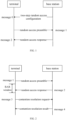
- a specific process is shown in FIG. 1 , including:
- Message 0 the network side configures for a user equipment (User Equipment, UE, also called a terminal), configuration information required for a simplified two-step random access, such as a transmission resource of a message 1 (Msgl);
- UE User Equipment
- Msgl message 1
- Message 1 the terminal selects a random access resource and uses the random access resource to transmit a selected random access signal (for example, a preamble (preamble)) to the base station; meanwhile, the Msg1 carries a UE identity, and through this identity, the network side can determine which UE transmits the random access request; in addition, Msg1 may further carry user plane data, which is suitable for UE in inactive state for small data transmission, thereby reducing signaling overhead during state transition of the UE.
- a selected random access signal for example, a preamble (preamble)
- Message 2 the network side transmits a random access response to the UE; the random access response should carry the UE identity to indicate whether the UE successfully contends for access. If the contention access is successful, the random access response may further carry information such as timing advance and uplink grant.
- the simplified two-step contention random access method can reduce the delay of the four-step contention random access, and is suitable for UE in active (active) state for small data transmission.
- Msg1 there is no solution for the transmission resource required for Msg1 in the simplified two-step contention random access.
- WO2018/064372A1 discloses a method for determining beam reciprocity for a beam of a wireless transmit/receive unit (WTRU).
- WTRU wireless transmit/receive unit
- PUSCH resources for the first message may be configured by higher layer signaling.
- Baseline handover procedure for inter gNB handover in NR (R2-1706705) discusses the basic handover procedure for inter gNB in NR.
- Embodiments of the present disclosure provide a random access method, a terminal and a network device, to solve the problem in the related art that there is no definite solution for the transmission resource required for Msg1 in the simplified two-step contention random access, which results in incomplete network communication procedures and inability to guarantee reliability of network communication.
- one embodiment of the present disclosure provides a random access method, performed by a terminal, including:
- one embodiment of the present disclosure provides a random access method, performed by a network device, including:
- one embodiment of the present disclosure provides a terminal, including:
- one embodiment of the present disclosure provides a network device, including:
- the first PUSCH resource for transmitting the message 1 in the simplified two-step contention random access is determined according to the configuration information of the simplified two-step contention random access, and transmission of the message 1 is realized, thereby improving network communication procedures and guarantying reliability of network communication.
- the random access procedure is mainly divided into: non-contention random access and contention random access.
- the contention random access procedure is shown in FIG. 2 and mainly divided into following four steps.
- Message 1 a terminal selects a random access resource and uses the random access resource to transmit a selected random access signal (for example, a preamble) to a base station. After transmitting the Msgl, according to transmission time and frequency position of Msgl, the terminal calculates identity information (i.e., Random Access Radio Network Temporary Identity (RA-RNTI)) of Msg2 scheduled on the network side. After transmitting the Msgl, the terminal monitors a downlink channel in a fixed window (i.e., Random Access Response window (RAR window) to obtain feedback information Msg2 from the network side.
- RA-RNTI Random Access Radio Network Temporary Identity
- Message 2 the base station receives the Msgl, calculates timing advance (TA), and transmits a random access response to the terminal.
- the random access response may include: Msg1 RAPID (i.e., identity information); timing advance command (i.e., uplink timing advance information); LTL grant (i.e., uplink transmission grant information); backoff indicator (i.e., back-off information); temporary C-RNTI (i.e., temporary terminal identity information).
- Msg1 RAPID i.e., identity information
- timing advance command i.e., uplink timing advance information
- LTL grant i.e., uplink transmission grant information
- backoff indicator i.e., back-off information
- temporary C-RNTI i.e., temporary terminal identity information
- the terminal determines a next moment for transmitting random access according to the backoff information indicated in the RAR (for example, contained in the RAR).
- Msg3 Message 3: the terminal transmits uplink transmission on a UL grant specified by the Msg2.
- Content of the uplink transmission of Msg3 is different for different random access reasons. For example, for initial access, Msg3 transmits radio resource control (RRC) connection establishment request. After transmitting Msg3, the terminal will start a contention resolution timer. If Msg4 has not been successfully received before the contention resolution timer expires, the UE considers that reception of Msg4 is unsuccessful.
- RRC radio resource control
- Msg4 Message 4 (Msg4): according to Msg4 which is a contention resolution message, the terminal can determine whether the random access is successful.
- NR In NR, cells often operate in high frequency bands, and loss of signals during space transmission is relatively large. If the whole cell is covered by a single beam, the base station is required to support a high transmit power.
- one cell may be covered by multiple beams, and the multiple beams operate in a time division manner. For example, one sector cell is covered by eight beams. The eight beams are transmitted in a time division manner, and the cell transmits only one beam at each moment.
- the UE identifies different beams according to reference symbols.
- Reference symbols There are two types of reference symbols: synchronization signal block (SSB) and channel state information-reference signal (CSI-RS).
- SSB synchronization signal block
- CSI-RS channel state information-reference signal
- the UE may determine a reference symbol to be monitored according to configurations of the network, and may determine, according to a received reference symbol, which one/several beams covers a position where the UE is located.
- the simplified two-step contention random access method can reduce the delay of the four-step contention random access, and may be suitable for UE in active state for small data transmission. However, there is no solution for the transmission resource required for Msg1 in the simplified two-step contention random access.
- the present disclosure provides a random access method, a terminal and a network device.
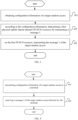
- one embodiment of the present disclosure provides a random access method, performed by a terminal, including: Step 301: obtaining configuration information of a target random access.
- the configuration information comprises an association relationship between reference signals and PUSCH resources.
- target random access refers to a simplified two-step contention random access.
- Step 302 according to the configuration information, determining a first physical uplink shared channel (PUSCH) resource for transmitting a message 1.
- PUSCH physical uplink shared channel
- Step 303 on the first PUSCH resource, transmitting the message 1 of the target random access.
- the first PUSCH resource for transmitting the message 1 is determined.
- the first PUSCH resource is mainly used to transmit user plane data and then transmit the message 1 of the simplified two-step contention random access. In this way, it defines a way of using the first PUSCH resource to transmit the message 1 of the simplified two-step contention random access.
- configuration information includes at least one of the following information, wherein option A2 below is mandatory according to the invention as claimed.
- A1 at least one reference signal monitored by the terminal.
- the at least one reference signal includes: at least one synchronization signal block (SSB) and/or at least one channel state information reference signal (CSI-RS).
- SSB synchronization signal block
- CSI-RS channel state information reference signal
- the at least one reference signal in the A1 information refers to at least one reference signal, which is configured by the network device for the terminal and which the terminal needs to monitor.
- the network device may configure one PUSCH resource for the terminal, and may also configure multiple PUSCH resources.
- the PUSCH resource includes: a grant-free resource and/or a pre-configured resource for a target random access.
- the pre-configured resource refers to a resource reserved by the network device for the simplified two-step contention random access.
- association relationship includes at least one of the following information.
- A21 there is a one-to-one relationship between the reference signal and the PUSCH resource.
- one reference signal is associated with only one PUSCH resource.
- reference signals monitored by the terminal include: SSB 1 and CSI-RS0, SSB1 corresponds to PUSCH resource 0, and CSI-RS0 corresponds to PUSCH resource 1.
- One PUSCH resource corresponds to at least one reference signal.
- the association relationship between PUSCH resources and reference signals is a one-to-many relationship, that is, one PUSCH resource corresponds to multiple reference signals.
- reference signals monitored by the terminal include SSB2 and SSB3
- the SSB2 corresponds to a PUSCH resource 2
- the SSB3 also corresponds to the PUSCH resource 2.
- One reference signal corresponds to at least one PUSCH resource.
- the association relationship between reference signals and PUSCH resources is a one-to-many relationship, that is, one reference signal corresponds to multiple PUSCH resources.
- reference signals monitored by the terminal include CSI-RS1 and CSI-RS2
- the CSI-RS1 corresponds to a PUSCH resource 3 and a PUSCH resource 4
- the CSI-RS2 corresponds to a PUSCH resource 5 and a PUSCH resource 6.
- any one of the foregoing association modes may be adopted, or some of them may be selected, or the foregoing three association modes may be selected simultaneously.
- reference signals monitored by the terminal include SSB4, SSB5, SSB6 and CSI-RS3, the SSB4 corresponds to a PUSCH resource 7, the SSB5 and the SSB6 correspond to a PUSCH resource 8, and the CSI-RS3 corresponds to a PUSCH resource 9 and a PUSCH resource 10.
- the performance indicator includes one of the following information: Reference signal receiving power (RSRP), reference signal receiving quality (RSRQ), and Signal to Interference and Noise Ratio (SINR).
- RSRP Reference signal receiving power
- RSS reference signal receiving quality
- SINR Signal to Interference and Noise Ratio
- the network device instructs the terminal to use only one performance indicator to select the first reference signal, and the performance indicator is any one of RSRP, RSRQ, and SINR.
- a preset threshold value for a performance indicator according to which the terminal selects a first reference signal from the at least one reference signal.
- the preset threshold value refers to a threshold standard on which the performance indicator is based when selecting the first reference signal. For example, if RSRP is taken as the performance indicator for selecting the first reference signal, when there is a reference signal with an actual measurement value of the performance indicator being greater than or equal to the preset threshold value, only the reference signal with an actual measurement value of the performance indicator being greater than or equal to the preset threshold value is selected as the first reference signal.
- step 101 may be implemented in at least one of the following ways:
- the network device may selectively transmit all information contained in the configuration information through a system broadcast message, or transmit all information contained in the configuration information through an RRC release message.
- the network device may also selectively transmit one part of the configuration information through a system broadcast message, and transmit other part of the configuration information through an RRC release message.
- step 102 includes: determining a first reference signal; determining one PUSCH resource from PUSCH resources associated with the first reference signal, as the first PUSCH resource for transmitting the message 1.
- This implementation process is as follows: the terminal first determines which reference signal is selected to determine the PUSCH resource; after the reference signal is determined, it is only necessary to determine one PUSCH resource for transmitting the message 1 from PUSCH resources associated with the reference signal.
- the manner of determining the first reference signal includes: C1. when there is a reference signal with a performance indicator being greater than or equal to the preset threshold value, determining one reference signal from at least one reference signal with the performance indicator being greater than or equal to the preset threshold value, as the first reference signal.
- the rule for selecting the first reference signal may include: randomly selecting one from the at least two reference signals with performance indicators being greater than or equal to the preset threshold value, as the first reference signal; or, selecting one, which meets a first preset condition, from the at least two reference signals with performance indicators being greater than or equal to the preset threshold value, as the first reference signal.
- the first preset condition includes at least one of the following conditions:
- time domain may be time domain corresponding to a random opportunity (RO) associated with the reference signal
- frequency domain refers to frequency domain corresponding to the RO associated with the reference signal
- an earliest available reference signal is selected. That is, a reference signal corresponding to an earliest RO in the time domain and/or an earliest RO in the frequency domain is taken as the earliest available reference signal.
- the terminal may randomly determine one of the reference signals configured by the network device for the terminal, as the first reference signal; or, the terminal may select one, which meets a first preset condition, from the reference signals configured by the network device for the terminal, as the first reference signal.
- the first preset condition has the same meaning as the foregoing first preset condition, that is, in this case, the terminal selects an earliest available reference signal.
- the first PUSCH resource needs to be determined according to the first reference signal. Specifically, the determining one PUSCH resource from PUSCH resources associated with the first reference signal, as the first PUSCH resource for transmitting the message 1, includes: D1. When the first reference signal is associated with one PUSCH resource, determining the PUSCH resource corresponding to the first reference signal as the first PUSCH resource.
- the PUSCH resource is taken as the first PUSCH resource.
- the first reference signal is associated with at least two PUSCH resources
- the target PUSCH resource is a random one of the at least two PUSCH resources associated with the first reference signal, or the target PUSCH resource is one PUSCH resource, which meets a second preset condition, of the at least two PUSCH resources associated with the first reference signal. That is, when the first reference signal is associated with multiple PUSCH resources, the terminal may randomly select one from the multiple PUSCH resources as the first PUSCH resource, or may select one PUSCH resource, which meets a second preset condition, from the multiple PUSCH resources as the first PUSCH resource.
- the second preset condition includes: time domain is less than or equal to a third preset threshold value.
- time domain here refers to time domain corresponding to the PUSCH resource, that is, in this case, the terminal selects an earliest available PUSCH resource as the first PUSCH resource.
- the terminal can select a PUSCH resource required for transmitting a message 1 of the simplified two-step contention random access, based on the association relationship between SSB (and/or CSI-RS) and PUSCH resources configured on the network side as well as ways of selecting SSB based on such as RSRP, thereby reducing access delay of the terminal as compared with four-step contention random access.
- the user plane data may be carried on the PUSCH resource, thereby reducing signaling overhead during state transition of the UE.
- FIG. 4 is a schematic flowchart of a random access performed by a network device side according to an embodiment of the present disclosure.
- the random access method performed by the network device includes:
- the message 1 is transmitted on a first PUSCH resource which is determined by the terminal for transmitting the message 1 according to the configuration information.
- the configuration information includes an association relationship between reference signals and PUSCH resources and may further include at least one of the following information:
- the association relationship includes at least one of the following information:
- the at least one reference signal includes at least one synchronization signal block (SSB) and/or at least one channel state information reference signal (CSI-RS).
- SSB synchronization signal block
- CSI-RS channel state information reference signal
- the performance indicator includes one of the following information: Reference signal receiving power (RSRP), reference signal receiving quality (RSRQ), and signal-to-noise ratio (SINR).
- RSRP Reference signal receiving power
- RSRQ reference signal receiving quality
- SINR signal-to-noise ratio
- the PUSCH resource includes: a grant-free resource and/or a pre-configured resource for a target random access.
- step 401 includes at least one of the following ways:
- a terminal 500 including:
- the configuration information includes an association relationship between reference signals and PUSCH resources and may further include at least one of the following information:
- the association relationship includes at least one of the following information:
- the at least one reference signal includes at least one synchronization signal block (SSB) and/or at least one channel state information reference signal (CSI-RS).
- SSB synchronization signal block
- CSI-RS channel state information reference signal
- the performance indicator includes one of the following information: Reference signal receiving power (RSRP), reference signal receiving quality (RSRQ), and signal-to-noise ratio (SINR).
- RSRP Reference signal receiving power
- RSRQ reference signal receiving quality
- SINR signal-to-noise ratio
- the PUSCH resource includes: a grant-free resource and/or a pre-configured resource for a target random access.
- the obtaining module 501 performs at least one of the following:
- the determining module 502 includes:
- the first determining submodule includes:
- the first determining unit is configured to, when there are at least two reference signals with performance indicators being greater than or equal to the preset threshold value, determine one of the at least two reference signals with performance indicators being greater than or equal to the preset threshold value, as the first reference signal.
- the first reference signal may be one randomly selected from the at least two reference signals; or, the first reference signal may be one, which meets a first preset condition, from the at least two reference signals.
- the second determining unit is configured to,
- the first preset condition includes at least one of the following conditions:
- the second determining submodule is configured to,
- the target PUSCH resource is a random one of the at least two PUSCH resources associated with the first reference signal, or the target PUSCH resource is one PUSCH resource, which meets a second preset condition, of the at least two PUSCH resources associated with the first reference signal.
- the second preset condition includes: time domain is less than or equal to a third preset threshold value.
- the terminal embodiment is a terminal corresponding to the foregoing random access method applied to the terminal side, and all implementation modes of the foregoing embodiments are applicable to this terminal embodiment and can also achieve the same technical effects.
- FIG. 6 is a schematic diagram of a hardware structure of a terminal according to an embodiment of the present disclosure.
- the terminal 60 includes, but is not limited to, a radio frequency unit 610, a network module 620, an audio output unit 630, an input unit 640, a sensor 650, a display unit 660, a user input unit 670, an interface unit 680, a memory 690, a processor 611, and a power supply 612. It will be appreciated by those skilled in the art that structures of the terminal shown in FIG. 6 do not constitute a limitation of the terminal, which may include more or fewer components than illustrated, or have some components combined, or different component arrangements.
- the terminal includes, but is not limited to, a mobile phone, a tablet computer, a notebook computer, a palmtop computer, an in-vehicle terminal, a wearable device, a pedometer, and the like.
- the processor 611 is configured to obtain configuration information of a target random access; according to the configuration information, determine a first physical uplink shared channel (PUSCH) resource for transmitting message 1; on the first PUSCH resource, transmit a message 1 of the target random access.
- PUSCH physical uplink shared channel
- the terminal of the embodiment of the present disclosure determines the first PUSCH resource for transmitting the message 1 in the simplified two-step contention random access according to the configuration information of the simplified two-step contention random access, and realizes transmission of the message 1, thereby improving network communication procedures and guarantying reliability of network communication.
- the radio frequency unit 610 may be used to receive and transmit signals during receiving and transmitting information or a call. Specifically, the radio frequency unit 610 receives downlink data from a network device and then transmits the downlink data to the processor 611 for processing. Uplink data is transmitted to the network device.
- the radio frequency unit 610 includes, but is not limited to, an antenna, at least one amplifier, a transceiver, a coupler, a low noise amplifier, a duplexer, and the like.
- the radio frequency unit 610 may also communicate with the network and other devices through a wireless communication system.
- the terminal provides wireless broadband internet access to the user through the network module 620, such as assisting the user in receiving and transmitting email, browsing web pages, and accessing streaming media.
- the audio output unit 630 may convert the audio data received by the radio frequency unit 610 or the network module 620 or stored in the memory 690 into an audio signal and output as sound. Moreover, the audio output unit 630 may also provide audio output (e.g., call signal reception sound, message reception sound, etc.) related to a specific function performed by the terminal 60.
- the audio output unit 630 includes a speaker, a buzzer, a receiver, and the like.
- the input unit 640 is used for receiving an audio or video signal.
- the input unit 640 may include a graphics processing unit (Graphics Processing Unit, GPU) 641 and a microphone 642.
- the GPU 641 processes image data of static pictures or videos obtained by an image capturing apparatus (such as a camera) in a video capturing mode or an image capturing mode.
- the processed image frame may be displayed on the display unit 660.
- the image frames processed by the graphics processor 641 may be stored in the memory 690 (or other storage medium) or transmitted via the radio frequency unit 610 or the network module 620.
- the microphone 642 can receive sound and can process such sound into audio data.
- the processed audio data may be converted into a format output that may be transmitted to the mobile communication base station via the radio frequency unit 610 in the case of a telephone talk mode.
- the terminal 60 further includes at least one sensor 650, such as a light sensor, a motion sensor, and other sensors.
- the light sensor includes an ambient light sensor and a proximity sensor.
- the ambient light sensor can adjust brightness of a display panel 661 according to the brightness of the ambient light.
- the proximity sensor can turn off the display panel 661 and/or backlight when the terminal 60 moves to the ear.
- an accelerometer sensor can detect the magnitude of the acceleration in each direction (generally three axes), can detect the magnitude and direction of the gravity when stationary, and can be used to identify the attitude of the terminal (such as horizontal or vertical screen switching, related games, magnetometer attitude calibration), vibration identification related functions (such as pedometer, knocking), and the like.
- the sensor 650 may further include a fingerprint sensor, a pressure sensor, an iris sensor, a molecular sensor, a gyroscope, a barometer, a hygrometer, a thermometer, an infrared sensor, and the like, which will not be elaborated herein.
- the display unit 660 is used to display information input by or provided to the user.
- the display unit 660 may include a display panel 661, which may be configured in the form of a liquid crystal display (Liquid Crystal Display, LCD), an organic light-emitting diode (Organic Light-Emitting Diode, OLED), or the like.
- LCD Liquid Crystal Display
- OLED Organic Light-Emitting Diode
- the user input unit 670 may be used to receive the input number or character information, and to generate a key signal input related to the user setting and the function control of the terminal.
- the user input unit 670 includes a touch panel 671 and other input devices 672.
- the touch panel 671 also referred to as a touch screen, may collect touch operations on or near the touch panel (e.g., operations on or near the touch panel 671 using any suitable object or accessory, such as a finger, stylus, or the like).
- the touch panel 671 may include a touch detection device and a touch controller.
- the touch detection device detects a touch orientation of the user, detects a signal generated by the touch operation, and transmits the signal to the touch controller.
- the touch controller receives touch information from the touch detection device and converts it into contact coordinates, which are then transmitted to the processor 611, receives commands from the processor 611 and execute them.
- the touch panel 671 may be implemented in various types such as a resistive type, a capacitive type, an infrared ray, and a surface acoustic wave.
- the user input unit 670 may further include other input devices 672.
- other input devices 672 may include, but are not limited to, a physical keyboard, a function key (such as a volume control key, an on-off key), a trackball, a mouse, and a joystick, which will not be elaborated herein.
- the touch panel 671 may be overlaid on the display panel 661.
- the touch panel 671 detects a touch operation on or near the touch panel, the touch panel 671 transmits it to the processor 611 to determine a type of a touch event. Then, the processor 611 provides a corresponding visual output on the display panel 661 according to the type of the touch event.
- the touch panel 671 and the display panel 661 are implemented as two separate components to implement the input and output functions of the terminal, in some embodiments, the touch panel 671 and the display panel 661 may be integrated to implement the input and output functions of the terminal, which are not specifically limited herein.
- the interface unit 680 is an interface through which an external device is connected to the terminal 60.
- the external device may include a wired or wireless headset port, an external power (or battery charger) port, a wired or wireless data port, a memory card port, a port for connecting a device having an identification module, an audio input/output (I/O) port, a video I/O port, a headset port, and the like.
- the interface unit 680 may be used to receive input (e.g., data information, power, etc.) from the external device and transmit the received input to one or more elements within the terminal 60 or may be used to transmit data between the terminal 60 and the external device.
- the memory 690 may be used to store software programs and various data.
- the memory 690 may mainly include a program storage area and a data storage area.
- the program storage area may store an operating system, an application program (such as a sound play function, an image play function) required by at least one function, and the like.
- the data storage area may store data (such as audio data, a phone book) created according to use of the mobile phone.
- the memory 690 may include high speed random access memory, and may also include non-volatile memory, such as at least one magnetic disk storage device, flash memory device, or other volatile solid state storage device.
- the processor 611 is a control center of the terminal, connects various parts of the entire terminal by various interfaces and lines, executes various functions of the terminal and processes data by running or executing software programs and/or modules stored in the memory 690 and invoking data stored in the memory 690, thereby performing overall monitoring of the terminal.
- the processor 611 may include one or more processing units.
- the processor 611 may integrate an application processor and a modem processor.
- the application processor primarily processes the operating system, the user interface and the application program.
- the modem processor primarily processes wireless communications. It will be appreciated that the modem processor may also not be integrated into the processor 611.
- the terminal 60 may further include a power source 612 (such as a battery) that supplies power to the various components.
- a power source 612 such as a battery
- the power source 612 may be logically connected to the processor 611 through a power management system to perform functions such as managing charging, discharging, and power consumption management through the power management system.
- the terminal 60 includes functional modules not shown, which will not be elaborated herein.
- one embodiment of the present disclosure further provides a terminal including a processor 611, a memory 690, and a computer program stored in the memory 690 and executable on the processor 611.
- a terminal including a processor 611, a memory 690, and a computer program stored in the memory 690 and executable on the processor 611.
- the computer program is executed by the processor 611, each of the processes of the random access method performed by the terminal side of the above embodiment is implemented, and the same technical effect can be achieved. To avoid repetition, details are not described herein.
- the computer readable storage medium stores a computer program.
- the computer program is executed by a processor to implement various processes of the random access method performed by the terminal side of the above embodiment, and the same technical effect can be achieved. To avoid repetition, details are not described herein.
- the computer readable storage medium may be, for example, a read-only memory (Read-Only Memory, ROM), a random access memory (Random Access Memory, RAM), a magnetic disk, or an optical disk.
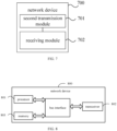
- one embodiment of the present disclosure further provides a network device 700, including:
- the message 1 is transmitted on a first PUSCH resource which is determined by the terminal for transmitting the message 1 according to the configuration information.
- the configuration information includes an association relationship between reference signals and PUSCH resources and may further include at least one of the following information:
- the association relationship includes at least one of the following information:
- the at least one reference signal includes at least one synchronization signal block (SSB) and/or at least one channel state information reference signal (CSI-RS).
- SSB synchronization signal block
- CSI-RS channel state information reference signal
- the performance indicator includes one of the following information: Reference signal receiving power (RSRP), reference signal receiving quality (RSRQ), and signal-to-noise ratio (SINR).
- RSRP Reference signal receiving power
- RSRQ reference signal receiving quality
- SINR signal-to-noise ratio
- the PUSCH resource includes: a grant-free resource and/or a pre-configured resource for a target random access.
- the second transmission module 701 is configured to perform at least one of the following ways:
- this network device embodiment is a network device corresponding to the foregoing random access method performed by the network-side device. All implementation modes of the foregoing embodiments are applicable to this network device embodiment, and the same technical effect can also be achieved.
- One embodiment of the present disclosure further provides a network device including a memory, a processor, and a computer program stored in the memory and executable on the processor.
- a network device including a memory, a processor, and a computer program stored in the memory and executable on the processor.
- the computer program is executed by the processor, each of the processes of the random access method performed by the network-side device side of the above embodiment is implemented, and the same technical effect can be achieved. To avoid repetition, details are not described herein.
- the computer readable storage medium stores a computer program.
- the computer program is executed by a processor to implement various processes of the random access method performed by the network-side device of the above embodiment, and the same technical effect can be achieved. To avoid repetition, details are not described herein.
- the computer readable storage medium may be, for example, a read-only memory (Read-Only Memory, ROM), a random access memory (Random Access Memory, RAM), a magnetic disk, or an optical disk.
- FIG. 8 is a structural diagram of a network device according to an embodiment of the present disclosure, which can implement details of the foregoing random access method performed by the network-side device and achieve the same effect.
- the network device 800 includes: a processor 801, a transceiver 802, a memory 803, and a bus interface.
- the processor 801 is configured to read programs from the memory 803 and execute the following processes:
- the message 1 is transmitted on a first PUSCH resource which is determined by the terminal for transmitting the message 1 according to the configuration information.
- a bus architecture may include any number of interconnected buses and bridges. Specifically, one or more processors demonstrated with processor 801 are coupled with various circuits of memory, which is demonstrated with memory 803.
- the bus architecture may also link various other circuits, such as, peripherals, voltage regulators, and power management circuits, as is known in the art. Thus, in the application, no further description is provided.
- the bus interface provides an interface.
- the transceiver 802 may be composed of multiple components, that is, including a transmitter and a receiver, which provide a unit for communicating with various other devices via the transmitting medium.
- the processor 801 is in charge of managing bus architecture and general processing.
- the memory 803 may store data used when the processor 801 performs operations.
- the configuration information includes an association relationship between reference signals and PUSCH resources and may further include at least one of the following information:
- the association relationship includes at least one of the following information:
- the at least one reference signal includes at least one synchronization signal block (SSB) and/or at least one channel state information reference signal (CSI-RS).
- SSB synchronization signal block
- CSI-RS channel state information reference signal
- the performance indicator includes one of the following information: Reference signal receiving power (RSRP), reference signal receiving quality (RSRQ), and signal-to-noise ratio (SINR).
- RSRP Reference signal receiving power
- RSRQ reference signal receiving quality
- SINR signal-to-noise ratio
- the PUSCH resource includes: a grant-free resource and/or a pre-configured resource for a target random access.
- the processor 801 is configured to read programs from the memory 803 and execute at least one of the following ways:
- the network device may be a Base Transceiver Station (Base Transceiver Station, BTS) in Global System of Mobile communication (Global System of Mobile communication, GSM) or Code Division Multiple Access (Code Division Multiple Access, CDMA), a NodeB (NodeB, NB) in Wideband Code Division Multiple Access (Wideband Code Division Multiple Access, WCDMA), an Evolutional Node B (Evolutional Node B, eNB or eNodeB) in LTE, a relay station, an access point, or a base station in a future 5G network, which is not limited herein.
- BTS Base Transceiver Station
- GSM Global System of Mobile communication
- CDMA Code Division Multiple Access
- NodeB NodeB
- WCDMA Wideband Code Division Multiple Access
- Evolutional Node B, eNB or eNodeB Evolutional Node B
- eNB Evolutional Node B
- eNodeB Evolutional Node B
- the person skilled in this field may be aware that the units and algorithmic steps of each embodiment described in the embodiments of the present disclosure can be realized by electronic hardware or a combination of the electronic hardware and computer software. Whether these functions are performed with hardware or software depends on the specific application and design constraints of the technical solution. Professionals may use different methods for each particular application to implement the described function, but such implementations should not be considered as beyond the scope of this disclosure.
- the electronic hardware includes but is not limited to, electronic circuits, specific application integrated circuits, programmable logic devices, programmable processors, etc.
Landscapes
- Engineering & Computer Science (AREA)
- Signal Processing (AREA)
- Computer Networks & Wireless Communication (AREA)
- Quality & Reliability (AREA)
- Mobile Radio Communication Systems (AREA)
- Transition And Organic Metals Composition Catalysts For Addition Polymerization (AREA)
Claims (15)
- Direktzugriffsverfahren, das von einem Endgerät durchgeführt wird, dadurch gekennzeichnet, dass es Folgendes umfasst:Erlangen (301) von Konfigurationsinformationen eines angestrebten Direktzugriffs;Bestimmen (302) einer Ressource eines ersten physischen geteilten Uplink-Kanals, PUSCH, zum Übertragen einer Nachricht 1 gemäß den Konfigurationsinformationen;auf der ersten PUSCH-Ressource, Übertragen (303) der Nachricht 1 des angestrebten Direktzugriffs;dadurch gekennzeichnet, dassdie Konfigurationsinformationen ein Assoziationsverhältnis zwischen Referenzsignalen und PUSCH-Ressourcen umfassen.
- Direktzugriffsverfahren nach Anspruch 1, wobei die Konfigurationsinformationen mindestens eine von folgenden Informationen umfassen:mindestens ein Referenzsignal, das von dem Endgerät überwacht wird;einen Leistungsindikator, gemäß dem das Endgerät ein erstes Referenzsignal aus dem mindestens einen Referenzsignal auswählt;einen voreingestellten Schwellenwert für einen Leistungsindikator, gemäß dem das Endgerät ein erstes Referenzsignal aus dem mindestens einen Referenzsignal auswählt.
- Direktzugriffsverfahren nach Anspruch 1, wobei die Assoziationsverhältnis mindestens eine von folgenden Informationen umfasst:es gibt ein eins-zu-eins-Verhältnis zwischen den Referenzsignalen und den PUSCH-Ressourcen;eine PUSCH-Ressource entspricht mindestens einem Referenzsignal;ein Referenzsignal entspricht mindestens einer PUSCH-Ressource.
- Direktzugriffsverfahren nach Anspruch 2, wobei das mindestens eine Referenzsignal mindestens einen Synchronisationssignalblock, SSB, und/oder mindestens ein Kanalzustandsinformation-Referenzsignal, CSI-RS, umfasst; oder
wobei die PUSCH-Ressource Folgendes umfasst: eine gewährungsfreie Ressource und/oder eine vorkonfigurierte Ressource für den angestrebten Direktzugriff. - Direktzugriffsverfahren nach Anspruch 2, wobei das Bestimmen einer Ressource eines ersten physischen geteilten Uplink-Kanals, PUSCH, zum Übertragen einer Nachricht 1 gemäß den Konfigurationsinformationen Folgendes umfasst:Bestimmen eines ersten Referenzsignals;Bestimmen einer PUSCH-Ressource aus den PUSCH-Ressourcen, die mit dem ersten Referenzsignal assoziiert sind, als erste PUSCH-Ressource zum Übertragen der Nachricht 1.
- Direktzugriffsverfahren nach Anspruch 5, wobei das Bestimmen eines ersten Referenzsignals Folgendes umfasst:wenn es ein Referenzsignal gibt, dessen Leistungsindikator größer als oder gleich wie ein voreingestellter Schwellenwert ist, Bestimmen eines Referenzsignals aus mindestens einem Referenzsignal, dessen Leistungsindikator größer als oder gleich wie der voreingestellte Schwellenwert ist, als erstes Referenzsignal; oderwenn es kein Referenzsignal mit einem Leistungsindikator gibt, der größer als oder gleich wie der voreingestellte Schwellenwert ist, Bestimmen eines Referenzsignals aus Referenzsignalen, die von einer Netzwerkvorrichtung für das Endgerät konfiguriert sind, als das erste Referenzsignal.
- Direktzugriffsverfahren nach Anspruch 6, wobei das Bestimmen eines Referenzsignals aus mindestens einem Referenzsignal, bei dem der Leistungsindikator größer als oder gleich wie der voreingestellte Schwellenwert ist, als erstes Referenzsignal Folgendes umfasst:wenn es mindestens zwei Referenzsignale gibt, deren Leistungsindikatoren größer als oder gleich wie der voreingestellte Schwellenwert sind, Bestimmen eines der mindestens zwei Referenzsignale, deren Leistungsindikatoren größer als oder gleich wie der voreingestellte Schwellenwert sind, als das erste Referenzsignal;wobei das erste Referenzsignal eines ist, das zufällig aus den mindestens zwei Referenzsignalen ausgewählt wird; oder das erste Referenzsignal eines ist, das eine erste voreingestellte Bedingung erfüllt, aus den mindestens zwei Referenzsignalen; oderwobei das Bestimmen eines Referenzsignals aus Referenzsignalen, die von einer Netzwerkvorrichtung für das Endgerät konfiguriert sind, als erstes Referenzsignal, Folgendes umfasst:zufälliges Auswählen eines der Referenzsignale, die von der Netzwerkvorrichtung für das Endgerät konfiguriert sind, als das erste Referenzsignal; oderAuswählen eines der Referenzsignale, die von der Netzwerkvorrichtung für das Endgerät konfiguriert sind, das eine erste vorgegebene Bedingung erfüllt, als erstes Referenzsignal.
- Direktzugriffsverfahren nach Anspruch 7, wobei die erste vorgegebene Bedingung mindestens eine von folgenden Bedingungen umfasst:
ein Referenzsignal, das einer frühesten zufälligen Gelegenheit (RO) in Zeitbereich und/oder einer frühesten RO in Frequenzbereich entspricht. - Direktzugriffsverfahren nach Anspruch 5, wobei das Bestimmen einer PUSCH-Ressource aus PUSCH-Ressourcen, die mit dem ersten Referenzsignal assoziiert sind, als erste PUSCH-Ressource zum Übertragen der Nachricht 1 Folgendes umfasst:wenn das erste Referenzsignal mit einer PUSCH-Ressource assoziiert ist, Bestimmen der PUSCH-Ressource, die dem ersten Referenzsignal entspricht, als die erste PUSCH-Ressource; oder,wenn das erste Referenzsignal mit mindestens zwei PUSCH-Ressourcen assoziiert ist, Auswählen einer angestrebten PUSCH-Ressource aus den mindestens zwei PUSCH-Ressourcen, die mit dem ersten Referenzsignal assoziiert sind, als erste PUSCH-Ressource.
- Direktzugriffsverfahren nach Anspruch 9, wobei die angestrebte PUSCH-Ressource eine zufällige der mindestens zwei PUSCH-Ressourcen ist, die mit dem ersten Referenzsignal assoziiert sind, oder die angestrebte PUSCH-Ressource eine PUSCH-Ressource ist, die eine zweite voreingestellte Bedingung der mindestens zwei PUSCH-Ressourcen erfüllt, die mit dem ersten Referenzsignal assoziiert sind.
- Direktzugriffsverfahren nach Anspruch 10, wobei die zweite vorgegebene Bedingung Folgendes umfasst: eine früheste verfügbare PUSCH-Ressource in Zeitbereich.
- Direktzugriffsverfahren nach Anspruch 2, wobei der Leistungsindikator eine von folgenden Informationen umfasst:
Referenzsignal-Empfangsleistung, RSRP, Referenzsignal-Empfangsqualität, RSRQ, und Signal-Rausch-Verhältnis, SINR. - Direktzugriffsverfahren, das von einer Netzwerkvorrichtung ausgeführt wird, dadurch gekennzeichnet, dass es Folgendes umfasst:Übertragen (401) von Konfigurationsinformationen eines angestrebten Direktzugriffs an ein Endgerät;Empfangen (402) einer Nachricht 1 des angestrebten Direktzugriffs, die von dem Endgerät zurückgesendet wird;wobei die Nachricht 1 auf einer ersten PUSCH-Ressource übertragen wird, die von dem Endgerät für die Übertragung der Nachricht 1 gemäß den Konfigurationsinformationen bestimmt wird;dadurch gekennzeichnet, dassdie Konfigurationsinformationen ein Assoziationsverhältnis zwischen Referenzsignalen und PUSCH-Ressourcen umfassen.
- Endgerät (500), dadurch gekennzeichnet, dass es Folgendes umfasst:ein Erlangungsmodul (501), das konfiguriert ist, um Konfigurationsinformationen eines angestrebten Direktzugriffs zu erlangen;ein Bestimmungsmodul (502), das konfiguriert ist, um gemäß den Konfigurationsinformationen eine Ressource eines ersten physischen geteilten Uplink-Kanals, PUSCH, zum Übertragen einer Nachricht 1 zu bestimmen;ein erstes Übertragungsmodul (503), das konfiguriert ist, um die Nachricht 1 des angestrebten Direktzugriffs auf der ersten PUSCH-Ressource zu übertragen;dadurch gekennzeichnet, dassdie Konfigurationsinformationen ein Assoziationsverhältnis zwischen Referenzsignalen und PUSCH-Ressourcen umfassen.
- Netzwerkvorrichtung (700), dadurch gekennzeichnet, dass sie Folgendes umfasst:ein zweites Übertragungsmodul (701), das konfiguriert ist, um Konfigurationsinformationen eines angestrebten Direktzugriffs an ein Endgerät zu übertragen;ein Empfangsmodul (702), das konfiguriert ist, um eine Nachricht 1 des angestrebten Direktzugriffs, die von dem Endgerät zurückgesendet wird, zu empfangen;dadurch gekennzeichnet, dassdie Nachricht 1 auf einer ersten PUSCH-Ressource übertragen wird, die von dem Endgerät für die Übertragung der Nachricht 1 gemäß den Konfigurationsinformationen bestimmt wird;wobei die Konfigurationsinformationen ein Assoziationsverhältnis zwischen Referenzsignalen und PUSCH-Ressourcen umfassen.
Applications Claiming Priority (2)
| Application Number | Priority Date | Filing Date | Title |
|---|---|---|---|
| CN201810837903.3A CN110769505B (zh) | 2018-07-26 | 2018-07-26 | 随机接入方法、终端及网络设备 |
| PCT/CN2019/097457 WO2020020212A1 (zh) | 2018-07-26 | 2019-07-24 | 随机接入方法、终端及网络设备 |
Publications (3)
| Publication Number | Publication Date |
|---|---|
| EP3829239A1 EP3829239A1 (de) | 2021-06-02 |
| EP3829239A4 EP3829239A4 (de) | 2021-10-13 |
| EP3829239B1 true EP3829239B1 (de) | 2023-07-05 |
Family
ID=69180829
Family Applications (1)
| Application Number | Title | Priority Date | Filing Date |
|---|---|---|---|
| EP19840767.8A Active EP3829239B1 (de) | 2018-07-26 | 2019-07-24 | Direktzugriffsverfahren, endgerät und netzwerkvorrichtung |
Country Status (11)
| Country | Link |
|---|---|
| US (1) | US12513779B2 (de) |
| EP (1) | EP3829239B1 (de) |
| JP (1) | JP7101862B2 (de) |
| KR (1) | KR102583091B1 (de) |
| CN (1) | CN110769505B (de) |
| ES (1) | ES2952006T3 (de) |
| HU (1) | HUE062486T2 (de) |
| MY (1) | MY209234A (de) |
| PT (1) | PT3829239T (de) |
| SG (1) | SG11202100855SA (de) |
| WO (1) | WO2020020212A1 (de) |
Families Citing this family (28)
| Publication number | Priority date | Publication date | Assignee | Title |
|---|---|---|---|---|
| CN110769505B (zh) * | 2018-07-26 | 2023-04-18 | 维沃移动通信有限公司 | 随机接入方法、终端及网络设备 |
| CN111436138A (zh) * | 2019-02-14 | 2020-07-21 | 维沃移动通信有限公司 | 信号传输方法、设备及系统 |
| KR102699440B1 (ko) * | 2020-02-13 | 2024-08-28 | 아서스테크 컴퓨터 인코포레이션 | 무선 통신 시스템에서 스몰 데이터 송신의 폴백 액션을 위한 방법 및 장치 |
| CN113260081B (zh) * | 2020-02-13 | 2023-05-30 | 大唐移动通信设备有限公司 | 一种数据传输处理方法、装置及存储介质 |
| WO2021174467A1 (zh) * | 2020-03-04 | 2021-09-10 | Oppo广东移动通信有限公司 | 一种数据传输方法、电子设备及存储介质 |
| CN113473641B (zh) * | 2020-03-31 | 2024-11-19 | 华为技术有限公司 | 一种通信方法和通信装置 |
| CN114982335B (zh) * | 2020-04-07 | 2025-01-28 | Oppo广东移动通信有限公司 | 数据传输方法、装置、存储介质、处理器及电子装置 |
| CN113518434B (zh) * | 2020-04-09 | 2025-09-09 | 华为技术有限公司 | 一种通信方法及装置 |
| CN113518370B (zh) * | 2020-04-10 | 2024-11-15 | 华为技术有限公司 | 一种移动性测量方法、装置及通信设备 |
| US11683840B2 (en) * | 2020-04-15 | 2023-06-20 | Qualcomm Incorporated | Techniques for user equipment (UE) procedures for random access channel (RACH) type selection and random access response (RAR) monitoring in a wireless communication system |
| WO2021223160A1 (zh) | 2020-05-07 | 2021-11-11 | Oppo广东移动通信有限公司 | 初始接入方法、受控设备和控制设备 |
| CN113677038B (zh) * | 2020-05-15 | 2023-07-25 | 维沃移动通信有限公司 | 随机接入处理方法和终端 |
| CN118317432A (zh) * | 2020-07-10 | 2024-07-09 | 北京小米移动软件有限公司 | 通信方法、装置、设备及存储介质 |
| CN114071553B (zh) * | 2020-07-29 | 2025-07-25 | 维沃移动通信有限公司 | Csi上报方法、终端及网络侧设备 |
| WO2022027638A1 (zh) * | 2020-08-07 | 2022-02-10 | Oppo广东移动通信有限公司 | 一种数据传输方法、电子设备及存储介质 |
| CN114080051B (zh) * | 2020-08-21 | 2024-09-17 | 中国移动通信有限公司研究院 | 一种两步随机接入方法、用户设备和网络侧设备 |
| CN114340031B (zh) * | 2020-09-29 | 2025-07-11 | 维沃移动通信有限公司 | 随机接入方法、装置、终端及可读存储介质 |
| US20230388960A1 (en) * | 2020-10-14 | 2023-11-30 | Beijing Xiaomi Mobile Software Co., Ltd. | Reference signal transmission method, apparatus and device, and readable storage medium |
| CN114630321B (zh) * | 2020-12-11 | 2023-10-13 | 大唐移动通信设备有限公司 | 数据传输方法及设备 |
| EP4316081B1 (de) * | 2021-03-30 | 2026-04-22 | Nokia Technologies Oy | Mechanismus für konfigurierte berechtigungsübertragung |
| CN117136623A (zh) * | 2021-06-17 | 2023-11-28 | Oppo广东移动通信有限公司 | 数据传输处理方法、装置、终端及存储介质 |
| CN119300171A (zh) * | 2021-08-05 | 2025-01-10 | 中国电信股份有限公司 | 接入网切片的随机接入资源选择方法及相关设备 |
| CN117223381A (zh) * | 2021-08-05 | 2023-12-12 | Oppo广东移动通信有限公司 | 随机接入条件的上报方法、终端设备及网络设备 |
| CN115942395A (zh) * | 2021-08-06 | 2023-04-07 | 维沃移动通信有限公司 | 信息上报方法、终端及网络侧设备 |
| CN115942502A (zh) * | 2021-08-23 | 2023-04-07 | 维沃移动通信有限公司 | 随机接入资源选择、配置方法、装置、终端及网络侧设备 |
| CN115884424A (zh) * | 2021-08-24 | 2023-03-31 | 大唐移动通信设备有限公司 | 随机接入方法、网络侧设备、终端、装置及存储介质 |
| CN115996479B (zh) * | 2021-10-20 | 2026-03-13 | 维沃移动通信有限公司 | 信息上报方法、设备及可读存储介质 |
| US20250168890A1 (en) * | 2022-01-27 | 2025-05-22 | Nec Corporation | Methods, devices, and computer readable medium for communication |
Family Cites Families (45)
| Publication number | Priority date | Publication date | Assignee | Title |
|---|---|---|---|---|
| CN105101455A (zh) * | 2007-09-27 | 2015-11-25 | 交互数字专利控股公司 | 分配资源至wtru的方法和wtru及由基站执行的方法和基站 |
| KR101238166B1 (ko) * | 2007-10-25 | 2013-02-28 | 인터디지탈 패튼 홀딩스, 인크 | Cell_fach상태의 wtru로부터 업링크 피드백 정보의 제어 및 전송 |
| CN103348756B (zh) * | 2011-02-10 | 2016-10-26 | 富士通株式会社 | 无线通信系统、接收装置、发送装置以及无线通信方法 |
| CN102905387B (zh) | 2011-07-25 | 2019-01-25 | 中兴通讯股份有限公司 | 随机接入方法及用户设备 |
| CN102932950B (zh) | 2011-08-09 | 2016-08-10 | 华为技术有限公司 | 一种在辅小区上随机接入的方法和设备 |
| CN103326840A (zh) * | 2012-03-23 | 2013-09-25 | 电信科学技术研究院 | 一种时分双工通信的方法、系统和设备 |
| CN102711187B (zh) * | 2012-05-18 | 2015-09-16 | 中兴通讯股份有限公司 | 一种控制超级小区中部分小区的激活状态的方法及装置 |
| US20150181546A1 (en) * | 2012-07-23 | 2015-06-25 | Interdigital Patent Holdings, Inc. | Methods and apparatus for frequency synchronization, power control, and cell configuration for ul-only operation in dss bands |
| CN104812084A (zh) * | 2014-01-28 | 2015-07-29 | 中兴通讯股份有限公司 | 配置信息的发送、获取方法、接入方法、通信节点及系统 |
| JP6248213B2 (ja) * | 2014-02-16 | 2017-12-13 | エルジー エレクトロニクス インコーポレイティド | 無線通信システムにおけるデータ送信方法及び装置 |
| CN106465401B (zh) * | 2014-02-28 | 2019-09-10 | Lg电子株式会社 | 在无线通信系统中发送具有低延迟的上行链路数据的方法和设备 |
| WO2015137632A1 (en) * | 2014-03-11 | 2015-09-17 | Lg Electronics Inc. | Method for allocating temporary identifier to terminal in random access procedure in wireless communication system and apparatus tehrefor |
| US9503242B2 (en) * | 2014-03-13 | 2016-11-22 | Amazon Technologies, Inc. | Device-to-device communication mode |
| US9730249B2 (en) * | 2014-11-19 | 2017-08-08 | Intel Corporation | Systems, apparatuses, and methods for processing random acccess response messages for coverage constrained devices |
| US10856313B2 (en) * | 2015-06-29 | 2020-12-01 | Telefonaktiebolaget Lm Ericsson (Publ) | Network node, wireless device and methods therein for managing uplink resources |
| CN106470468B (zh) | 2015-08-14 | 2020-08-07 | 电信科学技术研究院 | 一种随机接入响应的传输方法及装置 |
| WO2017209417A1 (ko) * | 2016-06-03 | 2017-12-07 | 엘지전자 주식회사 | 무선 통신 시스템에서 상향링크 제어 정보 전송 방법 및 이를 위한 장치 |
| WO2017222327A1 (ko) * | 2016-06-22 | 2017-12-28 | 엘지전자 주식회사 | 랜덤 액세스를 수행하는 방법 및 그 방법을 수행하는 단말 |
| JP2019534615A (ja) * | 2016-09-28 | 2019-11-28 | アイディーエーシー ホールディングス インコーポレイテッド | ビームフォーミングシステムにおけるNew Radioランダムアクセス |
| US10693605B2 (en) * | 2016-09-30 | 2020-06-23 | Qualcomm Incorporated | RACH transmission using multiple ports |
| CN107889244B (zh) * | 2016-09-30 | 2020-06-02 | 华为技术有限公司 | 通信方法、装置及计算机可读存储介质 |
| WO2018175249A1 (en) * | 2017-03-23 | 2018-09-27 | Intel IP Corporation | Narrowband internet-of-things (nb-iot) enhacements |
| EP3998820A1 (de) * | 2017-04-13 | 2022-05-18 | Huawei Technologies Co., Ltd. | Verfahren zur bestimmung eines netzwerkidentifikators zur verwendung durch benutzergeräte |
| WO2019024130A1 (en) * | 2017-08-02 | 2019-02-07 | Qualcomm Incorporated | CONFIGURATIONS FOR TRANSMITTING RANDOM ACCESS PREAMBLE MESSAGES |
| WO2019036940A1 (en) * | 2017-08-23 | 2019-02-28 | Qualcomm Incorporated | SYSTEMS AND METHODS USING USER EQUIPMENT LATENCY REQUIREMENT (UE) FOR SELECTION OF A SYNCHRONIZATION SIGNAL BLOCK |
| WO2019056105A1 (en) * | 2017-09-21 | 2019-03-28 | Sierra Wireless, Inc. | METHOD AND APPARATUS FOR SUPPORTING UPLINK TRANSMISSION OF A SUB-CHANNEL PHYSICAL RESOURCE BLOCK IN A WIRELESS COMMUNICATION SYSTEM |
| ES3055216T3 (en) * | 2017-09-28 | 2026-02-10 | Sony Group Corp | User equipment, base station and methods thereof |
| EP3487083B1 (de) * | 2017-11-17 | 2020-12-16 | ASUSTek Computer Inc. | Verfahren und vorrichtung zur überwachung des verhaltens einer benutzervorrichtung (ue) zur strahlwiederherstellung in einem drahtloskommunikationssystem |
| US10674518B2 (en) * | 2017-12-27 | 2020-06-02 | Comcast Cable Communications, Llc | Dynamic management of interference and coverage in wireless communications |
| EP3536091A4 (de) * | 2018-01-11 | 2020-07-01 | Telefonaktiebolaget LM Ericsson (publ) | Verfahren und system zur wiederherstellung eines strahlausfalls |
| CN111713166B (zh) * | 2018-02-14 | 2022-06-10 | 华为技术有限公司 | 随机接入方法及装置 |
| CN110167185B (zh) * | 2018-02-14 | 2022-05-17 | 华为技术有限公司 | 随机接入过程中传输数据的方法和装置 |
| EP3776900B1 (de) * | 2018-03-28 | 2021-08-11 | Telefonaktiebolaget LM Ericsson (publ) | Effiziente anzeige räumlicher beziehungen für ressourcen von physischem uplink-steuerkanal (pucch) |
| US10736046B2 (en) * | 2018-04-05 | 2020-08-04 | Lenovo (Singapore) Pte Ltd | Power headroom report for multiple uplink carriers |
| US11490428B2 (en) * | 2018-04-06 | 2022-11-01 | Mediatek Inc. | Initial access in new radio unlicensed spectrum |
| WO2019196098A1 (en) * | 2018-04-13 | 2019-10-17 | Qualcomm Incorporated | Measurement configuration for global cell identifier reporting |
| CN110417521B (zh) * | 2018-04-28 | 2022-01-11 | 华为技术有限公司 | 异步上行传输的方法、设备和存储介质 |
| US11088800B2 (en) * | 2018-05-31 | 2021-08-10 | Qualcomm Incorporated | Autonomous reference signal transmission configuration |
| US11277302B2 (en) * | 2018-06-21 | 2022-03-15 | Ofinno, Llc | PUCCH based beam failure recovery procedure |
| US11245499B2 (en) * | 2018-06-22 | 2022-02-08 | Qualcomm Incorporated | Signaling overhead reduction in NOMA |
| JP7148607B2 (ja) * | 2018-06-28 | 2022-10-05 | 株式会社Nttドコモ | 端末、無線通信方法、及びシステム |
| CN112602368B (zh) * | 2018-06-28 | 2024-08-20 | 株式会社Ntt都科摩 | 用户终端 |
| WO2020019138A1 (en) * | 2018-07-23 | 2020-01-30 | Qualcomm Incorporated | RESOURCES AND SCHEMES FOR GRANT-FREE UPLINK TRANSMISSION IN eMTC/NB-IoT |
| CN110769505B (zh) * | 2018-07-26 | 2023-04-18 | 维沃移动通信有限公司 | 随机接入方法、终端及网络设备 |
| KR102622888B1 (ko) * | 2021-01-15 | 2024-01-10 | 엘지전자 주식회사 | 채널 접속 절차를 수행하는 방법 및 이를 위한 장치 |
-
2018
- 2018-07-26 CN CN201810837903.3A patent/CN110769505B/zh active Active
-
2019
- 2019-07-24 SG SG11202100855SA patent/SG11202100855SA/en unknown
- 2019-07-24 PT PT198407678T patent/PT3829239T/pt unknown
- 2019-07-24 EP EP19840767.8A patent/EP3829239B1/de active Active
- 2019-07-24 WO PCT/CN2019/097457 patent/WO2020020212A1/zh not_active Ceased
- 2019-07-24 JP JP2021504366A patent/JP7101862B2/ja active Active
- 2019-07-24 KR KR1020217006068A patent/KR102583091B1/ko active Active
- 2019-07-24 HU HUE19840767A patent/HUE062486T2/hu unknown
- 2019-07-24 MY MYPI2021000451A patent/MY209234A/en unknown
- 2019-07-24 ES ES19840767T patent/ES2952006T3/es active Active
-
2021
- 2021-01-07 US US17/143,999 patent/US12513779B2/en active Active
Also Published As
| Publication number | Publication date |
|---|---|
| KR20210036968A (ko) | 2021-04-05 |
| ES2952006T3 (es) | 2023-10-26 |
| JP7101862B2 (ja) | 2022-07-15 |
| KR102583091B1 (ko) | 2023-09-25 |
| US12513779B2 (en) | 2025-12-30 |
| EP3829239A4 (de) | 2021-10-13 |
| HUE062486T2 (hu) | 2023-11-28 |
| EP3829239A1 (de) | 2021-06-02 |
| MY209234A (en) | 2025-06-30 |
| CN110769505B (zh) | 2023-04-18 |
| JP2021532668A (ja) | 2021-11-25 |
| US20210136831A1 (en) | 2021-05-06 |
| WO2020020212A1 (zh) | 2020-01-30 |
| SG11202100855SA (en) | 2021-02-25 |
| CN110769505A (zh) | 2020-02-07 |
| PT3829239T (pt) | 2023-08-17 |
Similar Documents
| Publication | Publication Date | Title |
|---|---|---|
| US12513779B2 (en) | Random access method, terminal and network device | |
| US11665571B2 (en) | Reference signal measurement method and user terminal | |
| US11234275B2 (en) | Method for receiving and sending information, user equipment and network device | |
| US20210168690A1 (en) | Information processing method for a radio link failure, terminal, and network device | |
| US12375154B2 (en) | Beam failure recovery method, terminal, and network device | |
| EP4037416B1 (de) | Datenempfangsverfahren, datenübersendungsverfahren, endgerät und netzseitige vorrichtung | |
| US11343855B2 (en) | Method and device for random access and terminal | |
| EP3691303B1 (de) | Funkrufverfahren, endgerät und netzseitige vorrichtung | |
| US20200314777A1 (en) | Process Method Of Synchronization Indication Information And Device, Indicating Method Of Synchronization Signal Block And Device | |
| EP3836596A1 (de) | Verfahren zur verarbeitung eines zellenstrahlausfalls, mobiles kommunikationsendgerät und netzseitige vorrichtung | |
| WO2019184716A1 (zh) | 波束失败处理方法、终端及网络设备 | |
| US11877339B2 (en) | Channel access method, configuration method, terminal, and network side device | |
| EP3706486B1 (de) | Direktzugriffsverfahren und benutzerendgerät | |
| US11601822B2 (en) | Random access method and communications device | |
| US12382510B2 (en) | Random access method, random access processing method, terminal, and network device | |
| HK40081096A (en) | Beam failure recovery method, terminal, and network device |
Legal Events
| Date | Code | Title | Description |
|---|---|---|---|
| STAA | Information on the status of an ep patent application or granted ep patent |
Free format text: STATUS: THE INTERNATIONAL PUBLICATION HAS BEEN MADE |
|
| PUAI | Public reference made under article 153(3) epc to a published international application that has entered the european phase |
Free format text: ORIGINAL CODE: 0009012 |
|
| STAA | Information on the status of an ep patent application or granted ep patent |
Free format text: STATUS: REQUEST FOR EXAMINATION WAS MADE |
|
| 17P | Request for examination filed |
Effective date: 20210225 |
|
| AK | Designated contracting states |
Kind code of ref document: A1 Designated state(s): AL AT BE BG CH CY CZ DE DK EE ES FI FR GB GR HR HU IE IS IT LI LT LU LV MC MK MT NL NO PL PT RO RS SE SI SK SM TR |
|
| A4 | Supplementary search report drawn up and despatched |
Effective date: 20210910 |
|
| RIC1 | Information provided on ipc code assigned before grant |
Ipc: H04W 74/00 20090101ALI20210906BHEP Ipc: H04W 74/08 20090101ALI20210906BHEP Ipc: H04W 72/08 20090101ALI20210906BHEP Ipc: H04W 72/04 20090101AFI20210906BHEP |
|
| DAV | Request for validation of the european patent (deleted) | ||
| DAX | Request for extension of the european patent (deleted) | ||
| REG | Reference to a national code |
Ref country code: DE Ref legal event code: R079 Free format text: PREVIOUS MAIN CLASS: H04W0072040000 Ipc: H04W0074080000 Ref country code: DE Ref legal event code: R079 Ref document number: 602019032306 Country of ref document: DE Free format text: PREVIOUS MAIN CLASS: H04W0072040000 Ipc: H04W0074080000 |
|
| RIC1 | Information provided on ipc code assigned before grant |
Ipc: H04L 5/00 20060101ALI20220926BHEP Ipc: H04W 74/08 20090101AFI20220926BHEP |
|
| GRAP | Despatch of communication of intention to grant a patent |
Free format text: ORIGINAL CODE: EPIDOSNIGR1 |
|
| STAA | Information on the status of an ep patent application or granted ep patent |
Free format text: STATUS: GRANT OF PATENT IS INTENDED |
|
| INTG | Intention to grant announced |
Effective date: 20221110 |
|
| GRAJ | Information related to disapproval of communication of intention to grant by the applicant or resumption of examination proceedings by the epo deleted |
Free format text: ORIGINAL CODE: EPIDOSDIGR1 |
|
| STAA | Information on the status of an ep patent application or granted ep patent |
Free format text: STATUS: REQUEST FOR EXAMINATION WAS MADE |
|
| INTC | Intention to grant announced (deleted) | ||
| GRAP | Despatch of communication of intention to grant a patent |
Free format text: ORIGINAL CODE: EPIDOSNIGR1 |
|
| STAA | Information on the status of an ep patent application or granted ep patent |
Free format text: STATUS: GRANT OF PATENT IS INTENDED |
|
| INTG | Intention to grant announced |
Effective date: 20230419 |
|
| GRAS | Grant fee paid |
Free format text: ORIGINAL CODE: EPIDOSNIGR3 |
|
| GRAA | (expected) grant |
Free format text: ORIGINAL CODE: 0009210 |
|
| STAA | Information on the status of an ep patent application or granted ep patent |
Free format text: STATUS: THE PATENT HAS BEEN GRANTED |
|
| AK | Designated contracting states |
Kind code of ref document: B1 Designated state(s): AL AT BE BG CH CY CZ DE DK EE ES FI FR GB GR HR HU IE IS IT LI LT LU LV MC MK MT NL NO PL PT RO RS SE SI SK SM TR |
|
| REG | Reference to a national code |
Ref country code: CH Ref legal event code: EP |
|
| REG | Reference to a national code |
Ref country code: AT Ref legal event code: REF Ref document number: 1585995 Country of ref document: AT Kind code of ref document: T Effective date: 20230715 |
|
| REG | Reference to a national code |
Ref country code: DE Ref legal event code: R096 Ref document number: 602019032306 Country of ref document: DE |
|
| REG | Reference to a national code |
Ref country code: IE Ref legal event code: FG4D |
|
| REG | Reference to a national code |
Ref country code: PT Ref legal event code: SC4A Ref document number: 3829239 Country of ref document: PT Date of ref document: 20230817 Kind code of ref document: T Free format text: AVAILABILITY OF NATIONAL TRANSLATION Effective date: 20230807 |
|
| REG | Reference to a national code |
Ref country code: NL Ref legal event code: FP |
|
| REG | Reference to a national code |
Ref country code: SK Ref legal event code: T3 Ref document number: E 41940 Country of ref document: SK |
|
| REG | Reference to a national code |
Ref country code: LT Ref legal event code: MG9D |
|
| REG | Reference to a national code |
Ref country code: ES Ref legal event code: FG2A Ref document number: 2952006 Country of ref document: ES Kind code of ref document: T3 Effective date: 20231026 |
|
| REG | Reference to a national code |
Ref country code: HU Ref legal event code: AG4A Ref document number: E062486 Country of ref document: HU |
|
| REG | Reference to a national code |
Ref country code: AT Ref legal event code: MK05 Ref document number: 1585995 Country of ref document: AT Kind code of ref document: T Effective date: 20230705 |
|
| PG25 | Lapsed in a contracting state [announced via postgrant information from national office to epo] |
Ref country code: GR Free format text: LAPSE BECAUSE OF FAILURE TO SUBMIT A TRANSLATION OF THE DESCRIPTION OR TO PAY THE FEE WITHIN THE PRESCRIBED TIME-LIMIT Effective date: 20231006 |
|
| PG25 | Lapsed in a contracting state [announced via postgrant information from national office to epo] |
Ref country code: IS Free format text: LAPSE BECAUSE OF FAILURE TO SUBMIT A TRANSLATION OF THE DESCRIPTION OR TO PAY THE FEE WITHIN THE PRESCRIBED TIME-LIMIT Effective date: 20231105 |
|
| PG25 | Lapsed in a contracting state [announced via postgrant information from national office to epo] |
Ref country code: SE Free format text: LAPSE BECAUSE OF FAILURE TO SUBMIT A TRANSLATION OF THE DESCRIPTION OR TO PAY THE FEE WITHIN THE PRESCRIBED TIME-LIMIT Effective date: 20230705 Ref country code: RS Free format text: LAPSE BECAUSE OF FAILURE TO SUBMIT A TRANSLATION OF THE DESCRIPTION OR TO PAY THE FEE WITHIN THE PRESCRIBED TIME-LIMIT Effective date: 20230705 Ref country code: NO Free format text: LAPSE BECAUSE OF FAILURE TO SUBMIT A TRANSLATION OF THE DESCRIPTION OR TO PAY THE FEE WITHIN THE PRESCRIBED TIME-LIMIT Effective date: 20231005 Ref country code: LV Free format text: LAPSE BECAUSE OF FAILURE TO SUBMIT A TRANSLATION OF THE DESCRIPTION OR TO PAY THE FEE WITHIN THE PRESCRIBED TIME-LIMIT Effective date: 20230705 Ref country code: LT Free format text: LAPSE BECAUSE OF FAILURE TO SUBMIT A TRANSLATION OF THE DESCRIPTION OR TO PAY THE FEE WITHIN THE PRESCRIBED TIME-LIMIT Effective date: 20230705 Ref country code: IS Free format text: LAPSE BECAUSE OF FAILURE TO SUBMIT A TRANSLATION OF THE DESCRIPTION OR TO PAY THE FEE WITHIN THE PRESCRIBED TIME-LIMIT Effective date: 20231105 Ref country code: HR Free format text: LAPSE BECAUSE OF FAILURE TO SUBMIT A TRANSLATION OF THE DESCRIPTION OR TO PAY THE FEE WITHIN THE PRESCRIBED TIME-LIMIT Effective date: 20230705 Ref country code: GR Free format text: LAPSE BECAUSE OF FAILURE TO SUBMIT A TRANSLATION OF THE DESCRIPTION OR TO PAY THE FEE WITHIN THE PRESCRIBED TIME-LIMIT Effective date: 20231006 Ref country code: FI Free format text: LAPSE BECAUSE OF FAILURE TO SUBMIT A TRANSLATION OF THE DESCRIPTION OR TO PAY THE FEE WITHIN THE PRESCRIBED TIME-LIMIT Effective date: 20230705 Ref country code: AT Free format text: LAPSE BECAUSE OF FAILURE TO SUBMIT A TRANSLATION OF THE DESCRIPTION OR TO PAY THE FEE WITHIN THE PRESCRIBED TIME-LIMIT Effective date: 20230705 |
|
| PG25 | Lapsed in a contracting state [announced via postgrant information from national office to epo] |
Ref country code: PL Free format text: LAPSE BECAUSE OF FAILURE TO SUBMIT A TRANSLATION OF THE DESCRIPTION OR TO PAY THE FEE WITHIN THE PRESCRIBED TIME-LIMIT Effective date: 20230705 |
|
| REG | Reference to a national code |
Ref country code: CH Ref legal event code: PL |
|
| REG | Reference to a national code |
Ref country code: BE Ref legal event code: MM Effective date: 20230731 |
|
| PG25 | Lapsed in a contracting state [announced via postgrant information from national office to epo] |
Ref country code: LU Free format text: LAPSE BECAUSE OF NON-PAYMENT OF DUE FEES Effective date: 20230724 |
|
| PG25 | Lapsed in a contracting state [announced via postgrant information from national office to epo] |
Ref country code: LU Free format text: LAPSE BECAUSE OF NON-PAYMENT OF DUE FEES Effective date: 20230724 |
|
| REG | Reference to a national code |
Ref country code: DE Ref legal event code: R097 Ref document number: 602019032306 Country of ref document: DE |
|
| REG | Reference to a national code |
Ref country code: IE Ref legal event code: MM4A |
|
| PG25 | Lapsed in a contracting state [announced via postgrant information from national office to epo] |
Ref country code: SM Free format text: LAPSE BECAUSE OF FAILURE TO SUBMIT A TRANSLATION OF THE DESCRIPTION OR TO PAY THE FEE WITHIN THE PRESCRIBED TIME-LIMIT Effective date: 20230705 Ref country code: RO Free format text: LAPSE BECAUSE OF FAILURE TO SUBMIT A TRANSLATION OF THE DESCRIPTION OR TO PAY THE FEE WITHIN THE PRESCRIBED TIME-LIMIT Effective date: 20230705 Ref country code: EE Free format text: LAPSE BECAUSE OF FAILURE TO SUBMIT A TRANSLATION OF THE DESCRIPTION OR TO PAY THE FEE WITHIN THE PRESCRIBED TIME-LIMIT Effective date: 20230705 Ref country code: DK Free format text: LAPSE BECAUSE OF FAILURE TO SUBMIT A TRANSLATION OF THE DESCRIPTION OR TO PAY THE FEE WITHIN THE PRESCRIBED TIME-LIMIT Effective date: 20230705 Ref country code: CZ Free format text: LAPSE BECAUSE OF FAILURE TO SUBMIT A TRANSLATION OF THE DESCRIPTION OR TO PAY THE FEE WITHIN THE PRESCRIBED TIME-LIMIT Effective date: 20230705 Ref country code: CH Free format text: LAPSE BECAUSE OF NON-PAYMENT OF DUE FEES Effective date: 20230731 Ref country code: MC Free format text: LAPSE BECAUSE OF FAILURE TO SUBMIT A TRANSLATION OF THE DESCRIPTION OR TO PAY THE FEE WITHIN THE PRESCRIBED TIME-LIMIT Effective date: 20230705 |
|
| PLBE | No opposition filed within time limit |
Free format text: ORIGINAL CODE: 0009261 |
|
| STAA | Information on the status of an ep patent application or granted ep patent |
Free format text: STATUS: NO OPPOSITION FILED WITHIN TIME LIMIT |
|
| PG25 | Lapsed in a contracting state [announced via postgrant information from national office to epo] |
Ref country code: BE Free format text: LAPSE BECAUSE OF NON-PAYMENT OF DUE FEES Effective date: 20230731 |
|
| 26N | No opposition filed |
Effective date: 20240408 |
|
| PG25 | Lapsed in a contracting state [announced via postgrant information from national office to epo] |
Ref country code: IE Free format text: LAPSE BECAUSE OF NON-PAYMENT OF DUE FEES Effective date: 20230724 |
|
| PG25 | Lapsed in a contracting state [announced via postgrant information from national office to epo] |
Ref country code: IE Free format text: LAPSE BECAUSE OF NON-PAYMENT OF DUE FEES Effective date: 20230724 Ref country code: SI Free format text: LAPSE BECAUSE OF FAILURE TO SUBMIT A TRANSLATION OF THE DESCRIPTION OR TO PAY THE FEE WITHIN THE PRESCRIBED TIME-LIMIT Effective date: 20230705 |
|
| PG25 | Lapsed in a contracting state [announced via postgrant information from national office to epo] |
Ref country code: BG Free format text: LAPSE BECAUSE OF FAILURE TO SUBMIT A TRANSLATION OF THE DESCRIPTION OR TO PAY THE FEE WITHIN THE PRESCRIBED TIME-LIMIT Effective date: 20230705 |
|
| PG25 | Lapsed in a contracting state [announced via postgrant information from national office to epo] |
Ref country code: BG Free format text: LAPSE BECAUSE OF FAILURE TO SUBMIT A TRANSLATION OF THE DESCRIPTION OR TO PAY THE FEE WITHIN THE PRESCRIBED TIME-LIMIT Effective date: 20230705 |
|
| PGFP | Annual fee paid to national office [announced via postgrant information from national office to epo] |
Ref country code: GB Payment date: 20250605 Year of fee payment: 7 |
|
| PGFP | Annual fee paid to national office [announced via postgrant information from national office to epo] |
Ref country code: NL Payment date: 20250613 Year of fee payment: 7 |
|
| PGFP | Annual fee paid to national office [announced via postgrant information from national office to epo] |
Ref country code: FR Payment date: 20250610 Year of fee payment: 7 |
|
| PG25 | Lapsed in a contracting state [announced via postgrant information from national office to epo] |
Ref country code: CY Free format text: LAPSE BECAUSE OF FAILURE TO SUBMIT A TRANSLATION OF THE DESCRIPTION OR TO PAY THE FEE WITHIN THE PRESCRIBED TIME-LIMIT; INVALID AB INITIO Effective date: 20190724 |
|
| PGFP | Annual fee paid to national office [announced via postgrant information from national office to epo] |
Ref country code: SK Payment date: 20250612 Year of fee payment: 7 |
|
| PGFP | Annual fee paid to national office [announced via postgrant information from national office to epo] |
Ref country code: HU Payment date: 20250630 Year of fee payment: 7 |
|
| PGFP | Annual fee paid to national office [announced via postgrant information from national office to epo] |
Ref country code: ES Payment date: 20250807 Year of fee payment: 7 Ref country code: PT Payment date: 20250716 Year of fee payment: 7 |
|
| PGFP | Annual fee paid to national office [announced via postgrant information from national office to epo] |
Ref country code: DE Payment date: 20250528 Year of fee payment: 7 |
|
| PGFP | Annual fee paid to national office [announced via postgrant information from national office to epo] |
Ref country code: IT Payment date: 20250623 Year of fee payment: 7 |
|
| PG25 | Lapsed in a contracting state [announced via postgrant information from national office to epo] |
Ref country code: TR Free format text: LAPSE BECAUSE OF FAILURE TO SUBMIT A TRANSLATION OF THE DESCRIPTION OR TO PAY THE FEE WITHIN THE PRESCRIBED TIME-LIMIT Effective date: 20230705 |