EP3829086A1 - Optical fiber power feeding system - Google Patents
Optical fiber power feeding system Download PDFInfo
- Publication number
- EP3829086A1 EP3829086A1 EP20850387.0A EP20850387A EP3829086A1 EP 3829086 A1 EP3829086 A1 EP 3829086A1 EP 20850387 A EP20850387 A EP 20850387A EP 3829086 A1 EP3829086 A1 EP 3829086A1
- Authority
- EP
- European Patent Office
- Prior art keywords
- power
- photoelectric conversion
- sourcing equipment
- electric power
- semiconductor
- Prior art date
- Legal status (The legal status is an assumption and is not a legal conclusion. Google has not performed a legal analysis and makes no representation as to the accuracy of the status listed.)
- Granted
Links
Images




Classifications
-
- H—ELECTRICITY
- H04—ELECTRIC COMMUNICATION TECHNIQUE
- H04B—TRANSMISSION
- H04B10/00—Transmission systems employing electromagnetic waves other than radio-waves, e.g. infrared, visible or ultraviolet light, or employing corpuscular radiation, e.g. quantum communication
- H04B10/80—Optical aspects relating to the use of optical transmission for specific applications, not provided for in groups H04B10/03 - H04B10/70, e.g. optical power feeding or optical transmission through water
- H04B10/806—Arrangements for feeding power
- H04B10/807—Optical power feeding, i.e. transmitting power using an optical signal
-
- H—ELECTRICITY
- H04—ELECTRIC COMMUNICATION TECHNIQUE
- H04B—TRANSMISSION
- H04B10/00—Transmission systems employing electromagnetic waves other than radio-waves, e.g. infrared, visible or ultraviolet light, or employing corpuscular radiation, e.g. quantum communication
- H04B10/25—Arrangements specific to fibre transmission
- H04B10/2589—Bidirectional transmission
-
- H—ELECTRICITY
- H04—ELECTRIC COMMUNICATION TECHNIQUE
- H04B—TRANSMISSION
- H04B10/00—Transmission systems employing electromagnetic waves other than radio-waves, e.g. infrared, visible or ultraviolet light, or employing corpuscular radiation, e.g. quantum communication
- H04B10/50—Transmitters
- H04B10/501—Structural aspects
- H04B10/503—Laser transmitters
-
- H—ELECTRICITY
- H04—ELECTRIC COMMUNICATION TECHNIQUE
- H04B—TRANSMISSION
- H04B10/00—Transmission systems employing electromagnetic waves other than radio-waves, e.g. infrared, visible or ultraviolet light, or employing corpuscular radiation, e.g. quantum communication
- H04B10/50—Transmitters
- H04B10/501—Structural aspects
- H04B10/506—Multiwavelength transmitters
-
- H—ELECTRICITY
- H04—ELECTRIC COMMUNICATION TECHNIQUE
- H04B—TRANSMISSION
- H04B10/00—Transmission systems employing electromagnetic waves other than radio-waves, e.g. infrared, visible or ultraviolet light, or employing corpuscular radiation, e.g. quantum communication
- H04B10/50—Transmitters
- H04B10/564—Power control
-
- H—ELECTRICITY
- H04—ELECTRIC COMMUNICATION TECHNIQUE
- H04B—TRANSMISSION
- H04B10/00—Transmission systems employing electromagnetic waves other than radio-waves, e.g. infrared, visible or ultraviolet light, or employing corpuscular radiation, e.g. quantum communication
- H04B10/60—Receivers
- H04B10/66—Non-coherent receivers, e.g. using direct detection
- H04B10/69—Electrical arrangements in the receiver
- H04B10/691—Arrangements for optimizing the photodetector in the receiver
Definitions
- the present disclosure relates to optical power supply.
- feed light converts electric power into light
- feed light transmits the feed light
- converts the feed light into electric energy uses the electric energy as electric power.
- Patent Literature 1 an optical communication device that includes: an optical transmitter that transmits signal light modulated with an electric signal and feed light for supplying electric power; an optical fiber including a core that transmits the signal light, a first cladding that is formed around the core, has a refractive index lower than that of the core, and transmits the feed light, and a second cladding that is formed around the first cladding, and has a refractive index lower than that of the first cladding; and an optical receiver that operates with electric power obtained by converting the feed light transmitted through the first cladding of the optical fiber, and converts the signal light transmitted through the core of the optical fiber into the electric signal.
- Patent Literature 1 JP 2010-135989 A
- an optical transmitter is provided with a new semiconductor laser in addition to a conventional semiconductor laser and/or an optical receiver is provided with a new photoelectric conversion element in addition to a conventional photoelectric conversion element.
- a power over fiber system is required to perform efficient power supply.
- a power over fiber system of an aspect of the present disclosure is
- the power over fiber system includes: a first data communication device including the power sourcing equipment; and a second data communication device including the powered device and performing optical communication with the first data communication device, and in the power over fiber system, the controller includes: a power-supplying-side controller included in the first data communication device and performing a process of switching the semiconductor lasers included in the power sourcing equipment to activate the one of the semiconductor lasers; and a power-receiving-side controller included in the second data communication device and performing a process of notifying, by the optical communication, the power-supplying-side controller of selection information for activating the one of the semiconductor lasers included in the power sourcing equipment and a process of switching the photoelectric conversion elements included in the powered device to activate the one of the photoelectric conversion elements.
- the power-supplying-side controller performs a process of activating the semiconductor lasers included in the power sourcing equipment one by one in order, and notifying, by the optical communication, the power-receiving-side controller of information for identifying a semiconductor laser being activated, and the power-receiving-side controller performs: a process of activating the photoelectric conversion elements included in the powered device one by one in order, and temporarily storing electric power data corresponding to respective combinations of the semiconductor lasers and the photoelectric conversion elements; a process of selecting electric power data satisfying a predetermined reference from among the stored electric power data; a process of notifying, by the optical communication, the power-supplying-side controller of the selection information to activate a semiconductor laser corresponding to the selected electric power data; and a process of switching the photoelectric conversion elements to activate a photoelectric conversion element corresponding to the selected electric power data.
- a power over fiber (PoF) system 1A (optical power supply system) of this embodiment includes a power sourcing equipment (PSE) 110, an optical fiber cable 200A and a powered device (PD) 310.
- PSE power sourcing equipment
- PD powered device
- a power sourcing equipment converts electric power into optical energy and supplies (sources) the optical energy, and a powered device receives (draws) the supplied optical energy and converts the optical energy into electric power.
- the power sourcing equipment 110 includes a semiconductor laser 111 for power supply.
- the optical fiber cable 200A includes an optical fiber 250A that forms a transmission path of feed light.
- the powered device 310 includes a photoelectric conversion element 311.
- the power sourcing equipment 110 is connected to a power source, and electrically drives the semiconductor laser 111 and so forth.
- the semiconductor laser 111 oscillates with the electric power from the power source, thereby outputting feed light 112.
- the optical fiber cable 200A has one end 201A connectable to the power sourcing equipment 110 and the other end 202A connectable to the powered device 310 to transmit the feed light 112.
- the feed light 112 from the power sourcing equipment 110 is input to the one end 201A of the optical fiber cable 200A, propagates through the optical fiber 250A, and is output from the other end 202A of the optical fiber cable 200A to the powered device 310.
- the photoelectric conversion element 311 converts the feed light 112 transmitted through the optical fiber cable 200A into electric power.
- the electric power obtained by the conversion of the feed light 112 by the photoelectric conversion element 311 is driving power needed in the powered device 310.
- the powered device 310 is capable of outputting, for an external device(s), the electric power obtained by the conversion of the feed light 112 by the photoelectric conversion element 311.
- Semiconductor materials of semiconductor regions of the semiconductor laser 111 and the photoelectric conversion element 311 are semiconductors having a laser wavelength being a short wavelength of 500 nm or less. The semiconductor regions exhibit light-electricity conversion effect.
- Semiconductors having a laser wavelength being a short wavelength have a large band gap and a high photoelectric conversion efficiency, and hence improve photoelectric conversion efficiency at the power supplying side and the power receiving side in optical power supply, and improve optical power supply efficiency.
- laser media having a laser wavelength (base wave) of 200 nm to 500 nm may be used.
- base wave examples thereof include diamond, gallium oxide, aluminum nitride and gallium nitride.
- semiconductors having a band gap of 2.4 eV or greater are used as the semiconductor materials.
- laser media having a band gap of 2.4 eV to 6.2 eV may be used.
- examples thereof include diamond, gallium oxide, aluminum nitride and gallium nitride.
- Laser light having a longer wavelength tends to have a higher transmission efficiency, whereas laser light having a shorter wavelength tends to have a higher photoelectric conversion efficiency.
- laser media having a laser wavelength (base wave) of greater than 500 nm may be used as the semiconductor materials, whereas when the photoelectric conversion efficiency is given priority, laser media having a laser wavelength (base wave) of less than 200 nm may be used as the semiconductor materials.
- any of these semiconductor materials may be used in one of the semiconductor laser 111 and the photoelectric conversion element 311. This improves the photoelectric conversion efficiency at either the power supplying side or the power receiving side, and improves the optical power supply efficiency.
- a power over fiber (PoF) system 1 of this embodiment includes a power supply system through an optical fiber and an optical communication system therethrough, and includes: a first data communication device 100 including a power sourcing equipment (PSE) 110; an optical fiber cable 200; and a second data communication device 300 including a powered device (PD) 310.
- PSE power sourcing equipment
- PD powered device
- the power sourcing equipment 110 includes a semiconductor laser 111 for power supply.
- the first data communication device 100 includes, in addition to the power sourcing equipment 110, a transmitter 120 and a receiver 130 for data communication.
- the first data communication device 100 corresponds to a data terminal equipment (DTE), a repeater or the like.
- the transmitter 120 includes a semiconductor laser 121 for signals and a modulator 122.
- the receiver 130 includes a photodiode 131 for signals.
- the optical fiber cable 200 includes an optical fiber 250 including: a core 210 that forms a transmission path of signal light; and a cladding 220 that is arranged so as to surround the core 210 and forms a transmission path of feed light.
- the powered device 310 includes a photoelectric conversion element 311.
- the second data communication device 300 includes, in addition to the powered device 310, a transmitter 320, a receiver 330 and a data processing unit 340.
- the second data communication device 300 corresponds to a power end station or the like.
- the transmitter 320 includes a semiconductor laser 321 for signals and a modulator 322.
- the receiver 330 includes a photodiode 331 for signals.
- the data processing unit 340 processes received signals.
- the second data communication device 300 is a node in a communication network.
- the second data communication device 300 may be a node that communicates with another node.
- the first data communication device 100 is connected to a power source, and electrically drives the semiconductor laser 111, the semiconductor laser 121, the modulator 122, the photodiode 131 and so forth.
- the first data communication device 100 is a node in a communication network.
- the first data communication device 100 may be a node that communicates with another node.
- the semiconductor laser 111 oscillates with the electric power from the power source, thereby outputting feed light 112.
- the photoelectric conversion element 311 converts the feed light 112 transmitted through the optical fiber cable 200 into electric power.
- the electric power obtained by the conversion of the feed light 112 by the photoelectric conversion element 311 is driving power needed in the second data communication device 300, for example, driving power for the transmitter 320, the receiver 330 and the data processing unit 340.
- the second data communication device 300 may be capable of outputting, for an external device(s), the electric power obtained by the conversion of the feed light 112 by the photoelectric conversion element 311.
- the modulator 122 of the transmitter 120 modulates laser light 123 output by the semiconductor laser 121 to signal light 125 on the basis of transmission data 124, and outputs the signal light 125.
- the photodiode 331 of the receiver 330 demodulates the signal light 125 transmitted through the optical fiber cable 200 to an electric signal, and outputs the electric signal to the data processing unit 340.
- the data processing unit 340 transmits data of the electric signal to a node, and also receives data from the node and outputs the data to the modulator 322 as transmission data 324.
- the modulator 322 of the transmitter 320 modulates laser light 323 output by the semiconductor laser 321 to signal light 325 on the basis of the transmission data 324, and outputs the signal light 325.
- the photodiode 131 of the receiver 130 demodulates the signal light 325 transmitted through the optical fiber cable 200 to an electric signal, and outputs the electric signal. Data of the electric signal is transmitted to a node, whereas data from the node is the transmission data 124.
- the feed light 112 and the signal light 125 from the first data communication device 100 are input to one end 201 of the optical fiber cable 200, propagate through the cladding 220 and the core 210, respectively, and are output from the other end 202 of the optical fiber cable 200 to the second data communication device 300.
- the signal light 325 from the second data communication device 300 is input to the other end 202 of the optical fiber cable 200, propagates through the core 210, and is output from the one end 201 of the optical fiber cable 200 to the first data communication device 100.
- the first data communication device 100 includes a light input/output part 140 and an optical connector 141 attached to the light input/output part 140
- the second data communication device 300 includes a light input/output part 350 and an optical connector 351 attached to the light input/output part 350
- An optical connector 230 provided at the one end 201 of the optical fiber cable 200 is connected to the optical connector 141
- an optical connector 240 provided at the other end 202 of the optical fiber cable 200 is connected to the optical connector 351.
- the light input/output part 140 guides the feed light 112 to the cladding 220, guides the signal light 125 to the core 210, and guides the signal light 325 to the receiver 130.
- the light input/output part 350 guides the feed light 112 to the powered device 310, guides the signal light 125 to the receiver 330, and guides the signal light 325 to the core 210.
- the optical fiber cable 200 has the one end 201 connectable to the first data communication device 100 and the other end 202 connectable to the second data communication device 300 to transmit the feed light 112.
- the optical fiber cable 200 transmits the signal light 125/325 bidirectionally.
- any of those described in the first embodiment can be used, thereby achieving a high optical power supply efficiency.
- an optical fiber 260 that transmits signal light and an optical fiber 270 that transmits feed light may be provided separately. Further, the optical fiber cable 200B may be composed of a plurality of optical fiber cables.
- the power over fiber system 1 shown in FIG. 5 includes: the first data communication device 100 including the power sourcing equipment 110; the second data communication device 300 including the powered device 310; and the optical fiber cable 200 for the first data communication device 100 and the second data communication device 300 to perform optical communication.
- the power sourcing equipment 110 included in the first data communication device 100 includes semiconductor lasers 111 for power supply that output the feed light of different wavelengths.
- the power sourcing equipment 110 of this example includes three semiconductor lasers 111a, 111b, 111c for power supply.
- the powered device 310 included in the second data communication device 300 includes a photoelectric conversion element 311 having a predetermined photoelectric conversion efficiency.
- the first data communication device 100 includes a power-supplying-side controller 150 that performs the process of switching the semiconductor lasers 111a, 111b, 111c included in the power sourcing equipment 110 to activate one of these.
- the second data communication device 300 includes a power-receiving-side controller 360 that performs a process of notifying, by optical communication, the power-supplying-side controller 150 of selection information for selecting and activating one of the semiconductor lasers 111a, 111b, 111c included in the power sourcing equipment 110.
- the power-receiving-side controller 360 and the power-supplying-side controller 150 cooperate with one another, thereby functioning as a controller that performs a process of selecting and activating one of the semiconductor lasers 111a, 111b, 111c included in the power sourcing equipment 110 for the power over fiber system 1 to perform power supply of predetermined electric power.
- the photoelectric conversion element 311 converts the feed light output by a semiconductor laser (111a, 111b or 111c) selected from among the semiconductor lasers 111a, 111b, 111c included in the power sourcing equipment 110 into electric power, so that predetermined power supply is performed.
- a semiconductor laser 111a, 111b or 111c
- the semiconductor lasers 111a, 111b, 111c included in the power sourcing equipment 110 are activated one by one, and the photoelectric conversion element 311 of the powered device 310 converts the feed light output by the respective semiconductor lasers 111a, 111b, 111c into electric power. Then, values of the electric power are compared with one another to select one of the semiconductor lasers 111a, 111b, 111c to be activated as a semiconductor laser for obtaining predetermined electric power, and the selected semiconductor laser is activated so that the power supply of the predetermined electric power is performed.
- the power-supplying-side controller 150 activates the semiconductor lasers 111a, 111b, 111c included in the power sourcing equipment 110 one by one in order, and sends the feed light output by the respective semiconductor lasers 111a, 111b, 111c to the photoelectric conversion element 311 of the powered device 310.
- the power-supplying-side controller 150 performs a process of notifying, by optical communication, the power-receiving-side controller 360 of information for identifying a semiconductor laser being activated among the semiconductor lasers 111a, 111b, 111c. More specifically, the power-supplying-side controller 150 outputs, as the signal light 125 from the transmitter 120, information for identifying a semiconductor laser being activated, thereby notifying the power-receiving-side controller 360 of the information.
- the photoelectric conversion element 311 of the powered device 310 converts the feed light output by the respective semiconductor lasers 111a, 111b, 111c in order into electric power.
- the power-receiving-side controller 360 performs a process of temporarily storing, in the storage 360a, electric power data corresponding to respective combinations of the semiconductor lasers 111a, 111b, 111c and the photoelectric conversion element 311.
- electric power data corresponding to the combination of the semiconductor laser 111a and the photoelectric conversion element 311, electric power data corresponding to the combination of the semiconductor laser 111b and the photoelectric conversion element 311, and electric power data corresponding to the combination of the semiconductor laser 111c and the photoelectric conversion element 311 are temporarily stored in the storage 360a.
- the power-receiving-side controller 360 performs a process of selecting electric power data satisfying a predetermined reference from among the stored electric power data. For example, the power-receiving-side controller 360 selects, as the electric power data satisfying a predetermined reference, the electric power data corresponding to the combination of the semiconductor laser 111b and the photoelectric conversion element 311 from among the three electric power data shown in FIG. 6 .
- the electric power data satisfying a predetermined reference is, for example, data on the electric power needed on the powered device 310 side or data on the maximum electric power obtained on the powered device 310 side.
- the power-receiving-side controller 360 performs the process of notifying, by optical communication, the power-supplying-side controller 150 of the selection information for activating the semiconductor laser 111b corresponding to the selected electric power data. More specifically, the power-receiving-side controller 360 outputs, as the signal light 325 from the transmitter 320, the selection information for activating the semiconductor laser 111b, thereby notifying the power-supplying-side controller 150 of the selection information.
- the power-supplying-side controller 150 selects and activates the semiconductor laser 111b among the semiconductor lasers 111a, 111b, 111c included in the power sourcing equipment 110.
- the power over fiber system 1 performs power supply with, among the semiconductor lasers 111a, 111b, 111c included in the power sourcing equipment 110, the semiconductor laser 111b activated.
- activating the semiconductor laser 111b selected by the controller allows the power over fiber system 1 of the first example to perform efficient power supply of predetermined electric power.
- the power over fiber system 1 shown in FIG. 7 includes: the first data communication device 100 including the power sourcing equipment 110; the second data communication device 300 including the powered device 310; and the optical fiber cable 200 for the first data communication device 100 and the second data communication device 300 to perform optical communication.
- the power sourcing equipment 110 included in the first data communication device 100 includes a semiconductor laser 111 for power supply that outputs the feed light of a predetermined wavelength.
- the powered device 310 included in the second data communication device 300 includes photoelectric conversion elements 311 having different photoelectric conversion efficiencies.
- the powered device 310 of this example includes three photoelectric conversion elements 311a, 311b, 311c.
- the first data communication device 100 includes the power-supplying-side controller 150 that collectively controls the components of the first data communication device 100.
- the second data communication device 300 includes the power-receiving-side controller 360 that performs the process of switching the photoelectric conversion elements 311a, 311b, 311c included in the powered device 310 to select and activate one of these.
- the power-receiving-side controller 360 and the power-supplying-side controller 150 cooperate with one another, thereby functioning as the controller that performs a process of selecting and activating one of the photoelectric conversion elements 311a, 311b, 311c included in the powered device 310 for the power over fiber system to perform power supply of predetermined electric power.
- a photoelectric conversion element (311a, 311b or 311c) selected from among the photoelectric conversion elements 311a, 311b, 311c included in the powered device 310 converts the feed light output by the semiconductor laser 111 of the power sourcing equipment 110 into electric power, so that predetermined power supply is performed.
- the photoelectric conversion elements 311a, 311b, 311c included in the powered device 310 are activated one by one, and each convert the feed light output by the semiconductor laser 111 into electric power. Then, values of the electric power are compared with one another to select one of the photoelectric conversion elements 311a, 311b, 311c to be activated as a photoelectric conversion element for obtaining predetermined electric power, and the selected photoelectric conversion element is activated so that the power supply of the predetermined electric power is performed.
- the power-supplying-side controller 150 activates the semiconductor laser 111 included in the power sourcing equipment 110, and sends the feed light output by the semiconductor laser 111 to the respective photoelectric conversion elements of the powered device 310.
- the power-receiving-side controller 360 activates the photoelectric conversion elements 311a, 311b, 311c included in the powered device 310 one by one in order, and the photoelectric conversion elements 311a, 311b, 311c of the powered device 310 each convert the feed light output by the semiconductor laser 111 into electric power.
- the power-receiving-side controller 360 performs a process of temporarily storing, in the storage 360a, electric power data corresponding to respective combinations of the semiconductor laser 111 of the power sourcing equipment 110 and the photoelectric conversion elements 311a, 311b, 311c.
- electric power data corresponding to the combination of the semiconductor laser 111 and the photoelectric conversion element 311a, electric power data corresponding to the combination of the semiconductor laser 111 and the photoelectric conversion element 311b, and electric power data corresponding to the combination of the semiconductor laser 111 and the photoelectric conversion element 311c are temporarily stored in the storage 360a.
- the power-receiving-side controller 360 performs the process of selecting electric power data satisfying a predetermined reference from among the stored electric power data. For example, the power-receiving-side controller 360 selects, as the electric power data satisfying a predetermined reference, the electric power data corresponding to the combination of the semiconductor laser 111 and the photoelectric conversion element 311b from among the three electric power data shown in FIG. 8 .
- the electric power data satisfying a predetermined reference is, for example, data on the electric power needed on the powered device 310 side or data on the maximum electric power obtained on the powered device 310 side.
- the power-receiving-side controller 360 performs the process of switching the photoelectric conversion elements to activate the photoelectric conversion element 311b corresponding to the selected electric power data, thereby selecting and activating the photoelectric conversion element 311b among the photoelectric conversion elements 311a, 311b, 311c included in the powered device 310.
- the power over fiber system 1 performs power supply with, among the photoelectric conversion elements 311a, 311b, 311c included in the powered device 310, the photoelectric conversion element 311b activated.
- activating the photoelectric conversion element 311b selected by the controller allows the power over fiber system 1 of the second example to perform efficient power supply of predetermined electric power.
- the power over fiber system 1 shown in FIG. 9 includes: the first data communication device 100 including the power sourcing equipment 110; the second data communication device 300 including the powered device 310; and the optical fiber cable 200 for the first data communication device 100 and the second data communication device 300 to perform optical communication.
- the power sourcing equipment 110 included in the first data communication device 100 includes semiconductor lasers 111 for power supply that output the feed light of different wavelengths.
- the power sourcing equipment 110 of this example includes three semiconductor lasers 111a, 111b, 111c for power supply.
- the powered device 310 included in the second data communication device 300 includes photoelectric conversion elements 311 having different photoelectric conversion efficiencies.
- the powered device 310 of this example includes three photoelectric conversion elements 311a, 311b, 311c.
- the first data communication device 100 includes the power-supplying-side controller 150 that performs the process of switching the semiconductor lasers 111a, 111b, 111c included in the power sourcing equipment 110 to activate one of these.
- the second data communication device 300 includes the power-receiving-side controller 360 that performs: the process of notifying, by optical communication, the power-supplying-side controller 150 of the selection information for selecting and activating one of the semiconductor lasers 111a, 111b, 111c included in the power sourcing equipment 110; and the process of switching the photoelectric conversion elements 311a, 311b, 311c included in the powered device 310 to select and activate one of these.
- the power-receiving-side controller 360 and the power-supplying-side controller 150 cooperate with one another, thereby functioning as the controller that performs the process of selecting and activating one of the semiconductor lasers 111a, 111b, 111c included in the power sourcing equipment 110 and the process of selecting and activating one of the photoelectric conversion elements 311a, 311b, 311c included in the powered device 310 for the power over fiber system 1 to perform power supply of predetermined electric power.
- a photoelectric conversion element (311a, 311b or 311c) selected from among the photoelectric conversion elements 311a, 311b, 311c included in the powered device 310 converts the feed light output by a semiconductor laser (111a, 111b or 111c) selected from among the semiconductor lasers 111a, 111b, 111c included in the power sourcing equipment 110 into electric power, so that predetermined power supply is performed.
- the semiconductor lasers 111a, 111b, 111c included in the power sourcing equipment 110 are activated one by one, and also the photoelectric conversion elements 311a, 311b, 311c included in the powered device 310 are activated one by one, and the photoelectric conversion elements 311a, 311b, 311c of the powered device 310 each convert the feed light output by the respective semiconductor lasers 111a, 111b, 111c of the power sourcing equipment 110 into electric power.
- values of the electric power are compared with one another to select one of the combinations of the semiconductor lasers 111 and the photoelectric conversion elements 311 to be activated as a combination for obtaining predetermined electric power, and the selected combination of the semiconductor laser and the photoelectric conversion element is activated so that the power supply of the predetermined electric power is performed.
- the power-supplying-side controller 150 activates the semiconductor lasers 111a, 111b, 111c included in the power sourcing equipment 110 one by one in order, and sends the feed light output by the respective semiconductor lasers 111a, 111b, 111c to the respective photoelectric conversion elements of the powered device 310.
- the power-supplying-side controller 150 performs the process of notifying, by optical communication, the power-receiving-side controller 360 of the information for identifying a semiconductor laser being activated among the semiconductor lasers 111a, 111b, 111c. More specifically, the power-supplying-side controller 150 outputs, as the signal light 125 from the transmitter 120, the information for identifying a semiconductor laser being activated, thereby notifying the power-receiving-side controller 360 of the information.
- the power-receiving-side controller 360 activates the photoelectric conversion elements 311a, 311b, 311c included in the powered device 310 one by one in order, and the photoelectric conversion elements 311a, 311b, 311c of the powered device 310 each convert the feed light output by the respective semiconductor lasers 111a, 111b, 111c into electric power.
- the power-receiving-side controller 360 performs the process of temporarily storing, in the storage 360a, electric power data corresponding to the respective combinations of the semiconductor lasers 111a, 111b, 111c and the photoelectric conversion elements 311a, 311b, 311c. For example, as shown in FIG.
- the power-receiving-side controller 360 performs the process of selecting electric power data satisfying a predetermined reference from among the stored electric power data. For example, the power-receiving-side controller 360 selects, as the electric power data satisfying a predetermined reference, the electric power data corresponding to the combination of the semiconductor laser 111b and the photoelectric conversion element 311b from among the nine electric power data shown in FIG. 10 .
- the electric power data satisfying a predetermined reference is, for example, data on the electric power needed on the powered device 310 side or data on the maximum electric power obtained on the powered device 310 side.
- the power-receiving-side controller 360 performs the process of notifying, by optical communication, the power-supplying-side controller 150 of the selection information for activating the semiconductor laser 111b corresponding to the selected electric power data. More specifically, the power-receiving-side controller 360 outputs, as the signal light 325 from the transmitter 320, the selection information for activating the semiconductor laser 111b, thereby notifying the power-supplying-side controller 150 of the selection information.
- the power-supplying-side controller 150 selects and activates the semiconductor laser 111b among the semiconductor lasers 111a, 111b, 111c included in the power sourcing equipment 110.
- the power-receiving-side controller 360 performs the process of switching the photoelectric conversion elements to activate the photoelectric conversion element 311b corresponding to the selected electric power data, thereby selecting and activating the photoelectric conversion element 311b among the photoelectric conversion elements 311a, 311b, 311c included in the powered device 310.
- the power over fiber system 1 performs power supply with, among the semiconductor lasers 111a, 111b, 111c included in the power sourcing equipment 110, the semiconductor laser 111b activated, and among the photoelectric conversion elements 311a, 311b, 311c included in the powered device 310, the photoelectric conversion element 311b activated.
- activating the semiconductor laser 111b and the photoelectric conversion element 311b selected by the controller allows the power over fiber system 1 of the third example to perform efficient power supply of predetermined electric power.
- the power sourcing equipment 110 includes the semiconductor lasers 111a, 111b, 111c that output the feed light of different wavelengths, and/or the powered device 310 includes the photoelectric conversion elements 311a, 311b, 311c having different photoelectric conversion efficiencies
- activating the semiconductor laser 111b and/or the photoelectric conversion element 311b selected by the controller allows the power over fiber system 1 to perform efficient power supply of predetermined electric power.
- the power-supplying-side controller 150 activates the semiconductor lasers 111a, 111b, 111c one by one in order, and sends the feed light output by the respective semiconductor lasers 111a, 111b, 111c to the photoelectric conversion element(s) of the powered device 310, and also the power-supplying-side controller 150 notifies, by optical communication, the power-receiving-side controller 360 of the information for identifying a semiconductor laser being activated, and the power-receiving-side controller 360 thereby identifies the semiconductor laser being activated on the power sourcing equipment 110 side, and stores electric power data corresponding to the respective combinations of the semiconductor lasers and the photoelectric conversion element(s).
- the present invention is not limited thereto.
- the power-receiving-side controller 360 notifies, by optical communication, the power-supplying-side controller 150 of request information on the order of the semiconductor lasers 111a, 111b, 111c to activate, the power-supplying-side controller 150 activates the semiconductor lasers 111a, 111b, 111c one by one in the requested order notified by the power-receiving-side controller 360, and the power-receiving-side controller 360 identifies a semiconductor laser being activated on the power sourcing equipment 110 side, and stores electric power data corresponding to the respective combinations of the semiconductor lasers and the photoelectric conversion element(s) .
- the present invention is configured as described above, and hence can be used as a power over fiber system.
Landscapes
- Physics & Mathematics (AREA)
- Electromagnetism (AREA)
- Engineering & Computer Science (AREA)
- Computer Networks & Wireless Communication (AREA)
- Signal Processing (AREA)
- Optics & Photonics (AREA)
- Optical Communication System (AREA)
- Optical Couplings Of Light Guides (AREA)
- Condensed Matter Physics & Semiconductors (AREA)
- General Physics & Mathematics (AREA)
Abstract
Description
- The present disclosure relates to optical power supply.
- Recently, there has been studied an optical power supply system that converts electric power into light (called feed light), transmits the feed light, converts the feed light into electric energy, and uses the electric energy as electric power.
- There is disclosed in
Patent Literature 1 an optical communication device that includes: an optical transmitter that transmits signal light modulated with an electric signal and feed light for supplying electric power; an optical fiber including a core that transmits the signal light, a first cladding that is formed around the core, has a refractive index lower than that of the core, and transmits the feed light, and a second cladding that is formed around the first cladding, and has a refractive index lower than that of the first cladding; and an optical receiver that operates with electric power obtained by converting the feed light transmitted through the first cladding of the optical fiber, and converts the signal light transmitted through the core of the optical fiber into the electric signal. - Patent Literature 1:
JP 2010-135989 A - In the course of future improvement of a power over fiber system, the following is expected; an optical transmitter is provided with a new semiconductor laser in addition to a conventional semiconductor laser and/or an optical receiver is provided with a new photoelectric conversion element in addition to a conventional photoelectric conversion element. In such a case too, a power over fiber system is required to perform efficient power supply.
- A power over fiber system of an aspect of the present disclosure is
- a power over fiber system including: a power sourcing equipment including a plurality of semiconductor lasers that oscillate with electric power, thereby outputting feed light; a powered device including a plurality of photoelectric conversion elements that convert the feed light from the power sourcing equipment into electric power; and an optical fiber cable that transmits the feed light from the power sourcing equipment to the powered device,
- wherein the power sourcing equipment includes the semiconductor lasers that output the feed light of different wavelengths,
- wherein the powered device includes the photoelectric conversion elements having different photoelectric conversion efficiencies, and
- wherein the power over fiber system further includes a controller that performs a process of selecting and activating one of the semiconductor lasers included in the power sourcing equipment and a process of selecting and activating one of the photoelectric conversion elements included in the powered device in order that the power over fiber system perform predetermined power supply.
- The power over fiber system includes: a first data communication device including the power sourcing equipment; and a second data communication device including the powered device and performing optical communication with the first data communication device, and
in the power over fiber system, the controller includes: a power-supplying-side controller included in the first data communication device and performing a process of switching the semiconductor lasers included in the power sourcing equipment to activate the one of the semiconductor lasers; and a power-receiving-side controller included in the second data communication device and performing a process of notifying, by the optical communication, the power-supplying-side controller of selection information for activating the one of the semiconductor lasers included in the power sourcing equipment and a process of switching the photoelectric conversion elements included in the powered device to activate the one of the photoelectric conversion elements. - In the power over fiber system,
the power-supplying-side controller performs a process of activating the semiconductor lasers included in the power sourcing equipment one by one in order, and notifying, by the optical communication, the power-receiving-side controller of information for identifying a semiconductor laser being activated, and
the power-receiving-side controller performs: a process of activating the photoelectric conversion elements included in the powered device one by one in order, and temporarily storing electric power data corresponding to respective combinations of the semiconductor lasers and the photoelectric conversion elements; a process of selecting electric power data satisfying a predetermined reference from among the stored electric power data; a process of notifying, by the optical communication, the power-supplying-side controller of the selection information to activate a semiconductor laser corresponding to the selected electric power data; and a process of switching the photoelectric conversion elements to activate a photoelectric conversion element corresponding to the selected electric power data. -
-
FIG. 1 is a block diagram of a power over fiber system according to a first embodiment of the present disclosure. -
FIG. 2 is a block diagram of a power over fiber system according to a second embodiment of the present disclosure. -
FIG. 3 is a block diagram of the power over fiber system according to the second embodiment of the present disclosure and shows optical connectors and so forth. -
FIG. 4 is a block diagram of a power over fiber system according to another embodiment of the present disclosure. -
FIG. 5 is a block diagram of the power over fiber system (first example) according to the second embodiment of the present disclosure with a controller(s) (power-receiving-side controller and power-supplying-side controller) added. -
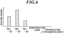
FIG. 6 is a graph to explain electric power data temporarily stored, in the first example. -
FIG. 7 is a block diagram of the power over fiber system (second example) according to the second embodiment of the present disclosure with the controller(s) (power-receiving-side controller and power-supplying-side controller) added. -
FIG. 8 is a graph to explain the electric power data temporarily stored, in the second example. -
FIG. 9 is a block diagram of the power over fiber system (third example) according to the second embodiment of the present disclosure with the controller(s) (power-receiving-side controller and power-supplying-side controller) added. -
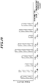
FIG. 10 is a graph to explain the electric power data temporarily stored, in the third example. - Hereinafter, embodiments of the present disclosure will be described with reference to the drawings.
- As shown in
FIG. 1 , a power over fiber (PoF) system 1A (optical power supply system) of this embodiment includes a power sourcing equipment (PSE) 110, anoptical fiber cable 200A and a powered device (PD) 310. - In the present disclosure, a power sourcing equipment converts electric power into optical energy and supplies (sources) the optical energy, and a powered device receives (draws) the supplied optical energy and converts the optical energy into electric power.
- The
power sourcing equipment 110 includes asemiconductor laser 111 for power supply. - The
optical fiber cable 200A includes anoptical fiber 250A that forms a transmission path of feed light. - The powered
device 310 includes aphotoelectric conversion element 311. - The
power sourcing equipment 110 is connected to a power source, and electrically drives thesemiconductor laser 111 and so forth. - The
semiconductor laser 111 oscillates with the electric power from the power source, thereby outputtingfeed light 112. - The
optical fiber cable 200A has oneend 201A connectable to thepower sourcing equipment 110 and theother end 202A connectable to the powereddevice 310 to transmit thefeed light 112. - The
feed light 112 from thepower sourcing equipment 110 is input to the oneend 201A of theoptical fiber cable 200A, propagates through theoptical fiber 250A, and is output from theother end 202A of theoptical fiber cable 200A to the powereddevice 310. - The
photoelectric conversion element 311 converts thefeed light 112 transmitted through theoptical fiber cable 200A into electric power. The electric power obtained by the conversion of thefeed light 112 by thephotoelectric conversion element 311 is driving power needed in the powereddevice 310. The powereddevice 310 is capable of outputting, for an external device(s), the electric power obtained by the conversion of thefeed light 112 by thephotoelectric conversion element 311. - Semiconductor materials of semiconductor regions of the
semiconductor laser 111 and thephotoelectric conversion element 311 are semiconductors having a laser wavelength being a short wavelength of 500 nm or less. The semiconductor regions exhibit light-electricity conversion effect. - Semiconductors having a laser wavelength being a short wavelength have a large band gap and a high photoelectric conversion efficiency, and hence improve photoelectric conversion efficiency at the power supplying side and the power receiving side in optical power supply, and improve optical power supply efficiency.
- Hence, as the semiconductor materials, laser media having a laser wavelength (base wave) of 200 nm to 500 nm may be used. Examples thereof include diamond, gallium oxide, aluminum nitride and gallium nitride.
- Further, as the semiconductor materials, semiconductors having a band gap of 2.4 eV or greater are used.
- For example, laser media having a band gap of 2.4 eV to 6.2 eV may be used. Examples thereof include diamond, gallium oxide, aluminum nitride and gallium nitride.
- Laser light having a longer wavelength tends to have a higher transmission efficiency, whereas laser light having a shorter wavelength tends to have a higher photoelectric conversion efficiency. Hence, when laser light is transmitted for a long distance, laser media having a laser wavelength (base wave) of greater than 500 nm may be used as the semiconductor materials, whereas when the photoelectric conversion efficiency is given priority, laser media having a laser wavelength (base wave) of less than 200 nm may be used as the semiconductor materials.
- Any of these semiconductor materials may be used in one of the
semiconductor laser 111 and thephotoelectric conversion element 311. This improves the photoelectric conversion efficiency at either the power supplying side or the power receiving side, and improves the optical power supply efficiency. - As shown in
FIG. 2 , a power over fiber (PoF)system 1 of this embodiment includes a power supply system through an optical fiber and an optical communication system therethrough, and includes: a firstdata communication device 100 including a power sourcing equipment (PSE) 110; anoptical fiber cable 200; and a seconddata communication device 300 including a powered device (PD) 310. - The
power sourcing equipment 110 includes asemiconductor laser 111 for power supply. The firstdata communication device 100 includes, in addition to thepower sourcing equipment 110, atransmitter 120 and areceiver 130 for data communication. The firstdata communication device 100 corresponds to a data terminal equipment (DTE), a repeater or the like. Thetransmitter 120 includes asemiconductor laser 121 for signals and amodulator 122. Thereceiver 130 includes aphotodiode 131 for signals. - The
optical fiber cable 200 includes anoptical fiber 250 including: a core 210 that forms a transmission path of signal light; and acladding 220 that is arranged so as to surround the core 210 and forms a transmission path of feed light. - The
powered device 310 includes aphotoelectric conversion element 311. The seconddata communication device 300 includes, in addition to thepowered device 310, atransmitter 320, areceiver 330 and adata processing unit 340. The seconddata communication device 300 corresponds to a power end station or the like. Thetransmitter 320 includes asemiconductor laser 321 for signals and amodulator 322. Thereceiver 330 includes aphotodiode 331 for signals. Thedata processing unit 340 processes received signals. The seconddata communication device 300 is a node in a communication network. The seconddata communication device 300 may be a node that communicates with another node. - The first
data communication device 100 is connected to a power source, and electrically drives thesemiconductor laser 111, thesemiconductor laser 121, themodulator 122, thephotodiode 131 and so forth. The firstdata communication device 100 is a node in a communication network. The firstdata communication device 100 may be a node that communicates with another node. - The
semiconductor laser 111 oscillates with the electric power from the power source, thereby outputtingfeed light 112. - The
photoelectric conversion element 311 converts thefeed light 112 transmitted through theoptical fiber cable 200 into electric power. The electric power obtained by the conversion of thefeed light 112 by thephotoelectric conversion element 311 is driving power needed in the seconddata communication device 300, for example, driving power for thetransmitter 320, thereceiver 330 and thedata processing unit 340. The seconddata communication device 300 may be capable of outputting, for an external device(s), the electric power obtained by the conversion of thefeed light 112 by thephotoelectric conversion element 311. - The
modulator 122 of thetransmitter 120 modulateslaser light 123 output by thesemiconductor laser 121 to signal light 125 on the basis oftransmission data 124, and outputs thesignal light 125. - The
photodiode 331 of thereceiver 330 demodulates thesignal light 125 transmitted through theoptical fiber cable 200 to an electric signal, and outputs the electric signal to thedata processing unit 340. Thedata processing unit 340 transmits data of the electric signal to a node, and also receives data from the node and outputs the data to themodulator 322 astransmission data 324. - The
modulator 322 of thetransmitter 320 modulateslaser light 323 output by thesemiconductor laser 321 to signal light 325 on the basis of thetransmission data 324, and outputs thesignal light 325. - The
photodiode 131 of thereceiver 130 demodulates thesignal light 325 transmitted through theoptical fiber cable 200 to an electric signal, and outputs the electric signal. Data of the electric signal is transmitted to a node, whereas data from the node is thetransmission data 124. - The
feed light 112 and the signal light 125 from the firstdata communication device 100 are input to oneend 201 of theoptical fiber cable 200, propagate through thecladding 220 and the core 210, respectively, and are output from theother end 202 of theoptical fiber cable 200 to the seconddata communication device 300. - The signal light 325 from the second
data communication device 300 is input to theother end 202 of theoptical fiber cable 200, propagates through the core 210, and is output from the oneend 201 of theoptical fiber cable 200 to the firstdata communication device 100. - As shown in
FIG. 3 , the firstdata communication device 100 includes a light input/output part 140 and anoptical connector 141 attached to the light input/output part 140, and the seconddata communication device 300 includes a light input/output part 350 and anoptical connector 351 attached to the light input/output part 350. Anoptical connector 230 provided at the oneend 201 of theoptical fiber cable 200 is connected to theoptical connector 141, and anoptical connector 240 provided at theother end 202 of theoptical fiber cable 200 is connected to theoptical connector 351. The light input/output part 140 guides thefeed light 112 to thecladding 220, guides thesignal light 125 to the core 210, and guides thesignal light 325 to thereceiver 130. The light input/output part 350 guides thefeed light 112 to thepowered device 310, guides thesignal light 125 to thereceiver 330, and guides thesignal light 325 to the core 210. - As described above, the
optical fiber cable 200 has the oneend 201 connectable to the firstdata communication device 100 and theother end 202 connectable to the seconddata communication device 300 to transmit thefeed light 112. In this embodiment, theoptical fiber cable 200 transmits thesignal light 125/325 bidirectionally. - As the semiconductor materials of the semiconductor regions, which exhibit the light-electricity conversion effect, of the
semiconductor laser 111 and thephotoelectric conversion element 311, any of those described in the first embodiment can be used, thereby achieving a high optical power supply efficiency. - Like an
optical fiber cable 200B of a power over fiber system 1B shown inFIG. 4 , anoptical fiber 260 that transmits signal light and anoptical fiber 270 that transmits feed light may be provided separately. Further, theoptical fiber cable 200B may be composed of a plurality of optical fiber cables. - Next, there will be described a process of switching
semiconductor lasers 111 for power supply included in thepower sourcing equipment 110 to activate one of these and a process of switchingphotoelectric conversion elements 311 included in thepowered device 310 to activate one of these for the power overfiber system 1 to perform efficient power supply. - The power over
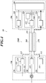
fiber system 1 shown inFIG. 5 includes: the firstdata communication device 100 including thepower sourcing equipment 110; the seconddata communication device 300 including thepowered device 310; and theoptical fiber cable 200 for the firstdata communication device 100 and the seconddata communication device 300 to perform optical communication. - As shown in
FIG. 5 , thepower sourcing equipment 110 included in the firstdata communication device 100 includessemiconductor lasers 111 for power supply that output the feed light of different wavelengths. Thepower sourcing equipment 110 of this example includes threesemiconductor lasers - The
powered device 310 included in the seconddata communication device 300 includes aphotoelectric conversion element 311 having a predetermined photoelectric conversion efficiency. - The first
data communication device 100 includes a power-supplying-side controller 150 that performs the process of switching thesemiconductor lasers power sourcing equipment 110 to activate one of these. - The second
data communication device 300 includes a power-receiving-side controller 360 that performs a process of notifying, by optical communication, the power-supplying-side controller 150 of selection information for selecting and activating one of thesemiconductor lasers power sourcing equipment 110. - The power-receiving-
side controller 360 and the power-supplying-side controller 150 cooperate with one another, thereby functioning as a controller that performs a process of selecting and activating one of thesemiconductor lasers power sourcing equipment 110 for the power overfiber system 1 to perform power supply of predetermined electric power. - That is, the
photoelectric conversion element 311 converts the feed light output by a semiconductor laser (111a, 111b or 111c) selected from among thesemiconductor lasers power sourcing equipment 110 into electric power, so that predetermined power supply is performed. - For example, in the power over
fiber system 1, regularly, thesemiconductor lasers power sourcing equipment 110 are activated one by one, and thephotoelectric conversion element 311 of thepowered device 310 converts the feed light output by therespective semiconductor lasers semiconductor lasers - Next, the process of selecting and activating one of the
semiconductor lasers power sourcing equipment 110, which is performed in the power overfiber system 1 of this first example, will be described. - For example, at predetermined regular timing, the power-supplying-
side controller 150 activates thesemiconductor lasers power sourcing equipment 110 one by one in order, and sends the feed light output by therespective semiconductor lasers photoelectric conversion element 311 of thepowered device 310. - At the time, the power-supplying-
side controller 150 performs a process of notifying, by optical communication, the power-receiving-side controller 360 of information for identifying a semiconductor laser being activated among thesemiconductor lasers side controller 150 outputs, as the signal light 125 from thetransmitter 120, information for identifying a semiconductor laser being activated, thereby notifying the power-receiving-side controller 360 of the information. - The
photoelectric conversion element 311 of thepowered device 310 converts the feed light output by therespective semiconductor lasers - At the time, on the basis of the information notified by the power-supplying-
side controller 150, the power-receiving-side controller 360 performs a process of temporarily storing, in thestorage 360a, electric power data corresponding to respective combinations of thesemiconductor lasers photoelectric conversion element 311. For example, as shown inFIG. 6 , electric power data corresponding to the combination of thesemiconductor laser 111a and thephotoelectric conversion element 311, electric power data corresponding to the combination of thesemiconductor laser 111b and thephotoelectric conversion element 311, and electric power data corresponding to the combination of thesemiconductor laser 111c and thephotoelectric conversion element 311 are temporarily stored in thestorage 360a. - Next, the power-receiving-
side controller 360 performs a process of selecting electric power data satisfying a predetermined reference from among the stored electric power data. For example, the power-receiving-side controller 360 selects, as the electric power data satisfying a predetermined reference, the electric power data corresponding to the combination of thesemiconductor laser 111b and thephotoelectric conversion element 311 from among the three electric power data shown inFIG. 6 . The electric power data satisfying a predetermined reference is, for example, data on the electric power needed on thepowered device 310 side or data on the maximum electric power obtained on thepowered device 310 side. - Next, the power-receiving-
side controller 360 performs the process of notifying, by optical communication, the power-supplying-side controller 150 of the selection information for activating thesemiconductor laser 111b corresponding to the selected electric power data. More specifically, the power-receiving-side controller 360 outputs, as the signal light 325 from thetransmitter 320, the selection information for activating thesemiconductor laser 111b, thereby notifying the power-supplying-side controller 150 of the selection information. - Then, on the basis of the selection information notified by the power-receiving-
side controller 360, the power-supplying-side controller 150 selects and activates thesemiconductor laser 111b among thesemiconductor lasers power sourcing equipment 110. - In this manner, the power over
fiber system 1 performs power supply with, among thesemiconductor lasers power sourcing equipment 110, thesemiconductor laser 111b activated. - Thus, activating the
semiconductor laser 111b selected by the controller (power-supplying-side controller 150 and power-receiving-side controller 360) allows the power overfiber system 1 of the first example to perform efficient power supply of predetermined electric power. - The power over
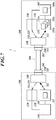
fiber system 1 shown inFIG. 7 includes: the firstdata communication device 100 including thepower sourcing equipment 110; the seconddata communication device 300 including thepowered device 310; and theoptical fiber cable 200 for the firstdata communication device 100 and the seconddata communication device 300 to perform optical communication. - As shown in
FIG. 7 , thepower sourcing equipment 110 included in the firstdata communication device 100 includes asemiconductor laser 111 for power supply that outputs the feed light of a predetermined wavelength. - The
powered device 310 included in the seconddata communication device 300 includesphotoelectric conversion elements 311 having different photoelectric conversion efficiencies. Thepowered device 310 of this example includes threephotoelectric conversion elements - The first
data communication device 100 includes the power-supplying-side controller 150 that collectively controls the components of the firstdata communication device 100. - The second
data communication device 300 includes the power-receiving-side controller 360 that performs the process of switching thephotoelectric conversion elements powered device 310 to select and activate one of these. - The power-receiving-
side controller 360 and the power-supplying-side controller 150 cooperate with one another, thereby functioning as the controller that performs a process of selecting and activating one of thephotoelectric conversion elements powered device 310 for the power over fiber system to perform power supply of predetermined electric power. - That is, a photoelectric conversion element (311a, 311b or 311c) selected from among the
photoelectric conversion elements powered device 310 converts the feed light output by thesemiconductor laser 111 of thepower sourcing equipment 110 into electric power, so that predetermined power supply is performed. - For example, in the power over
fiber system 1, regularly, thephotoelectric conversion elements powered device 310 are activated one by one, and each convert the feed light output by thesemiconductor laser 111 into electric power. Then, values of the electric power are compared with one another to select one of thephotoelectric conversion elements - Next, the process of selecting and activating one of the
photoelectric conversion elements powered device 310, which is performed in the power overfiber system 1 of this second example, will be described. - For example, at predetermined regular timing, the power-supplying-
side controller 150 activates thesemiconductor laser 111 included in thepower sourcing equipment 110, and sends the feed light output by thesemiconductor laser 111 to the respective photoelectric conversion elements of thepowered device 310. - At the timing, the power-receiving-
side controller 360 activates thephotoelectric conversion elements powered device 310 one by one in order, and thephotoelectric conversion elements powered device 310 each convert the feed light output by thesemiconductor laser 111 into electric power. - At the time, the power-receiving-
side controller 360 performs a process of temporarily storing, in thestorage 360a, electric power data corresponding to respective combinations of thesemiconductor laser 111 of thepower sourcing equipment 110 and thephotoelectric conversion elements FIG. 8 , electric power data corresponding to the combination of thesemiconductor laser 111 and thephotoelectric conversion element 311a, electric power data corresponding to the combination of thesemiconductor laser 111 and thephotoelectric conversion element 311b, and electric power data corresponding to the combination of thesemiconductor laser 111 and thephotoelectric conversion element 311c are temporarily stored in thestorage 360a. - Next, the power-receiving-
side controller 360 performs the process of selecting electric power data satisfying a predetermined reference from among the stored electric power data. For example, the power-receiving-side controller 360 selects, as the electric power data satisfying a predetermined reference, the electric power data corresponding to the combination of thesemiconductor laser 111 and thephotoelectric conversion element 311b from among the three electric power data shown inFIG. 8 . The electric power data satisfying a predetermined reference is, for example, data on the electric power needed on thepowered device 310 side or data on the maximum electric power obtained on thepowered device 310 side. - Next, the power-receiving-
side controller 360 performs the process of switching the photoelectric conversion elements to activate thephotoelectric conversion element 311b corresponding to the selected electric power data, thereby selecting and activating thephotoelectric conversion element 311b among thephotoelectric conversion elements powered device 310. - In this manner, the power over
fiber system 1 performs power supply with, among thephotoelectric conversion elements powered device 310, thephotoelectric conversion element 311b activated. - Thus, activating the
photoelectric conversion element 311b selected by the controller (power-supplying-side controller 150 and power-receiving-side controller 360) allows the power overfiber system 1 of the second example to perform efficient power supply of predetermined electric power. - The power over
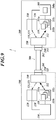
fiber system 1 shown inFIG. 9 includes: the firstdata communication device 100 including thepower sourcing equipment 110; the seconddata communication device 300 including thepowered device 310; and theoptical fiber cable 200 for the firstdata communication device 100 and the seconddata communication device 300 to perform optical communication. - As shown in
FIG. 9 , thepower sourcing equipment 110 included in the firstdata communication device 100 includessemiconductor lasers 111 for power supply that output the feed light of different wavelengths. Thepower sourcing equipment 110 of this example includes threesemiconductor lasers - The
powered device 310 included in the seconddata communication device 300 includesphotoelectric conversion elements 311 having different photoelectric conversion efficiencies. Thepowered device 310 of this example includes threephotoelectric conversion elements - The first
data communication device 100 includes the power-supplying-side controller 150 that performs the process of switching thesemiconductor lasers power sourcing equipment 110 to activate one of these. - The second
data communication device 300 includes the power-receiving-side controller 360 that performs: the process of notifying, by optical communication, the power-supplying-side controller 150 of the selection information for selecting and activating one of thesemiconductor lasers power sourcing equipment 110; and the process of switching thephotoelectric conversion elements powered device 310 to select and activate one of these. - The power-receiving-
side controller 360 and the power-supplying-side controller 150 cooperate with one another, thereby functioning as the controller that performs the process of selecting and activating one of thesemiconductor lasers power sourcing equipment 110 and the process of selecting and activating one of thephotoelectric conversion elements powered device 310 for the power overfiber system 1 to perform power supply of predetermined electric power. - That is, a photoelectric conversion element (311a, 311b or 311c) selected from among the
photoelectric conversion elements powered device 310 converts the feed light output by a semiconductor laser (111a, 111b or 111c) selected from among thesemiconductor lasers power sourcing equipment 110 into electric power, so that predetermined power supply is performed. - For example, in the power over
fiber system 1, regularly, thesemiconductor lasers power sourcing equipment 110 are activated one by one, and also thephotoelectric conversion elements powered device 310 are activated one by one, and thephotoelectric conversion elements powered device 310 each convert the feed light output by therespective semiconductor lasers power sourcing equipment 110 into electric power. Then, values of the electric power are compared with one another to select one of the combinations of thesemiconductor lasers 111 and thephotoelectric conversion elements 311 to be activated as a combination for obtaining predetermined electric power, and the selected combination of the semiconductor laser and the photoelectric conversion element is activated so that the power supply of the predetermined electric power is performed. - Next, the process of selecting and activating one of the
semiconductor lasers power sourcing equipment 110 and the process of selecting and activating one of thephotoelectric conversion elements powered device 310, which are performed in the power overfiber system 1 of this third example, will be described. - For example, at predetermined regular timing, the power-supplying-
side controller 150 activates thesemiconductor lasers power sourcing equipment 110 one by one in order, and sends the feed light output by therespective semiconductor lasers powered device 310. - At the time, the power-supplying-
side controller 150 performs the process of notifying, by optical communication, the power-receiving-side controller 360 of the information for identifying a semiconductor laser being activated among thesemiconductor lasers side controller 150 outputs, as the signal light 125 from thetransmitter 120, the information for identifying a semiconductor laser being activated, thereby notifying the power-receiving-side controller 360 of the information. - Also, at the timing, the power-receiving-
side controller 360 activates thephotoelectric conversion elements powered device 310 one by one in order, and thephotoelectric conversion elements powered device 310 each convert the feed light output by therespective semiconductor lasers - At the time, on the basis of the information notified by the power-supplying-
side controller 150, the power-receiving-side controller 360 performs the process of temporarily storing, in thestorage 360a, electric power data corresponding to the respective combinations of thesemiconductor lasers photoelectric conversion elements FIG. 10 , electric power data corresponding to the combination of thesemiconductor laser 111a and thephotoelectric conversion element 311a, electric power data corresponding to the combination of thesemiconductor laser 111a and thephotoelectric conversion element 311b, electric power data corresponding to the combination of thesemiconductor laser 111a and thephotoelectric conversion element 311c, electric power data corresponding to the combination of thesemiconductor laser 111b and thephotoelectric conversion element 311a, electric power data corresponding to the combination of thesemiconductor laser 111b and thephotoelectric conversion element 311b, electric power data corresponding to the combination of thesemiconductor laser 111b and thephotoelectric conversion element 311c, electric power data corresponding to the combination of thesemiconductor laser 111c and thephotoelectric conversion element 311a, electric power data corresponding to the combination of thesemiconductor laser 111c and thephotoelectric conversion element 311b, and electric power data corresponding to the combination of thesemiconductor laser 111c and thephotoelectric conversion element 311c are temporarily stored in thestorage 360a. - Next, the power-receiving-
side controller 360 performs the process of selecting electric power data satisfying a predetermined reference from among the stored electric power data. For example, the power-receiving-side controller 360 selects, as the electric power data satisfying a predetermined reference, the electric power data corresponding to the combination of thesemiconductor laser 111b and thephotoelectric conversion element 311b from among the nine electric power data shown inFIG. 10 . The electric power data satisfying a predetermined reference is, for example, data on the electric power needed on thepowered device 310 side or data on the maximum electric power obtained on thepowered device 310 side. - Next, the power-receiving-
side controller 360 performs the process of notifying, by optical communication, the power-supplying-side controller 150 of the selection information for activating thesemiconductor laser 111b corresponding to the selected electric power data. More specifically, the power-receiving-side controller 360 outputs, as the signal light 325 from thetransmitter 320, the selection information for activating thesemiconductor laser 111b, thereby notifying the power-supplying-side controller 150 of the selection information. - Then, on the basis of the selection information notified by the power-receiving-
side controller 360, the power-supplying-side controller 150 selects and activates thesemiconductor laser 111b among thesemiconductor lasers power sourcing equipment 110. - Also, the power-receiving-
side controller 360 performs the process of switching the photoelectric conversion elements to activate thephotoelectric conversion element 311b corresponding to the selected electric power data, thereby selecting and activating thephotoelectric conversion element 311b among thephotoelectric conversion elements powered device 310. - In this manner, the power over
fiber system 1 performs power supply with, among thesemiconductor lasers power sourcing equipment 110, thesemiconductor laser 111b activated, and among thephotoelectric conversion elements powered device 310, thephotoelectric conversion element 311b activated. - Thus, activating the
semiconductor laser 111b and thephotoelectric conversion element 311b selected by the controller (power-supplying-side controller 150 and power-receiving-side controller 360) allows the power overfiber system 1 of the third example to perform efficient power supply of predetermined electric power. - As described above, even when the
power sourcing equipment 110 includes thesemiconductor lasers powered device 310 includes thephotoelectric conversion elements semiconductor laser 111b and/or thephotoelectric conversion element 311b selected by the controller (power-supplying-side controller 150 and power-receiving-side controller 360) allows the power overfiber system 1 to perform efficient power supply of predetermined electric power. - In the power over
fiber system 1 of the first example and the power overfiber system 1 of the third example described above, the power-supplying-side controller 150 activates thesemiconductor lasers respective semiconductor lasers powered device 310, and also the power-supplying-side controller 150 notifies, by optical communication, the power-receiving-side controller 360 of the information for identifying a semiconductor laser being activated, and the power-receiving-side controller 360 thereby identifies the semiconductor laser being activated on thepower sourcing equipment 110 side, and stores electric power data corresponding to the respective combinations of the semiconductor lasers and the photoelectric conversion element(s). However, the present invention is not limited thereto. - For example, it is possible that the power-receiving-
side controller 360 notifies, by optical communication, the power-supplying-side controller 150 of request information on the order of thesemiconductor lasers side controller 150 activates thesemiconductor lasers side controller 360, and the power-receiving-side controller 360 identifies a semiconductor laser being activated on thepower sourcing equipment 110 side, and stores electric power data corresponding to the respective combinations of the semiconductor lasers and the photoelectric conversion element(s) . - Although some embodiments of the present disclosure have been described above, these embodiments are made for purposes of illustration and example only. The present invention can be carried out in various other forms, and each component may be omitted, replaced or modified/changed within a range not departing from the scope of the present invention.
- The present invention is configured as described above, and hence can be used as a power over fiber system.
-
- 1A Power over Fiber System (Optical Power Supply System)
- 1 Power over Fiber System (Optical Power Supply System)
- 1B Power over Fiber System (Optical Power Supply System)
- 100 First Data Communication Device
- 110 Power Sourcing Equipment
- 111 (111a, 111b, 111c) Semiconductor Laser for Power Supply
- 112 Feed Light
- 120 Transmitter
- 125 Signal Light
- 130 Receiver
- 140 Light Input/Output Part
- 141 Optical Connector
- 150 Power-supplying-side Controller
- 200A Optical Fiber Cable
- 200 Optical Fiber Cable
- 200B Optical Fiber Cable
- 210 Core
- 220 Cladding
- 250A Optical Fiber
- 250 Optical Fiber
- 260 Optical Fiber
- 270 Optical Fiber
- 300 Second Data Communication Device
- 311 (311a, 311b, 311c) Powered Device
- 320 Transmitter
- 325 Signal Light
- 330 Receiver
- 350 Light Input/Output Part
- 351 Optical Connector
- 360 Power-receiving-side Controller
- 360a Storage
Claims (12)
- A power over fiber system comprising: a power sourcing equipment including a plurality of semiconductor lasers that oscillate with electric power, thereby outputting feed light; a powered device including a plurality of photoelectric conversion elements that convert the feed light from the power sourcing equipment into electric power; and an optical fiber cable that transmits the feed light from the power sourcing equipment to the powered device,
wherein the power sourcing equipment includes the semiconductor lasers that output the feed light of different wavelengths,
wherein the powered device includes the photoelectric conversion elements having different photoelectric conversion efficiencies, and
wherein the power over fiber system further comprises a controller that performs a process of selecting and activating one of the semiconductor lasers included in the power sourcing equipment and a process of selecting and activating one of the photoelectric conversion elements included in the powered device in order that the power over fiber system perform predetermined power supply. - The power over fiber system according to claim 1 comprising: a first data communication device including the power sourcing equipment; and a second data communication device including the powered device and performing optical communication with the first data communication device,
wherein the controller includes: a power-supplying-side controller included in the first data communication device and performing a process of switching the semiconductor lasers included in the power sourcing equipment to activate the one of the semiconductor lasers; and a power-receiving-side controller included in the second data communication device and performing a process of notifying, by the optical communication, the power-supplying-side controller of selection information for activating the one of the semiconductor lasers included in the power sourcing equipment and a process of switching the photoelectric conversion elements included in the powered device to activate the one of the photoelectric conversion elements. - The power over fiber system according to claim 2,
wherein the power-supplying-side controller performs a process of activating the semiconductor lasers included in the power sourcing equipment one by one in order, and notifying, by the optical communication, the power-receiving-side controller of information for identifying a semiconductor laser being activated, and
wherein the power-receiving-side controller performs:
a process of activating the photoelectric conversion elements included in the powered device one by one in order, and temporarily storing electric power data corresponding to respective combinations of the semiconductor lasers and the photoelectric conversion elements; a process of selecting electric power data satisfying a predetermined reference from among the stored electric power data; a process of notifying, by the optical communication, the power-supplying-side controller of the selection information to activate a semiconductor laser corresponding to the selected electric power data; and a process of switching the photoelectric conversion elements to activate a photoelectric conversion element corresponding to the selected electric power data. - The power over fiber system according to any one of claims 1 to 3, wherein a semiconductor material of each of a semiconductor region of at least one of the semiconductor lasers and a semiconductor region of at least one of the photoelectric conversion elements is a laser medium having a laser wavelength of 500 nm or less, the semiconductor regions exhibiting a light-electricity conversion effect.
- A power over fiber system comprising: a power sourcing equipment including a plurality of semiconductor lasers that oscillate with electric power, thereby outputting feed light; a powered device including a photoelectric conversion element that converts the feed light from the power sourcing equipment into electric power; and an optical fiber cable that transmits the feed light from the power sourcing equipment to the powered device,
wherein the power sourcing equipment includes the semiconductor lasers that output the feed light of different wavelengths,
wherein the powered device includes the photoelectric conversion element having a predetermined photoelectric conversion efficiency, and
wherein the power over fiber system further comprises a controller that performs a process of selecting and activating one of the semiconductor lasers included in the power sourcing equipment in order that the power over fiber system perform predetermined power supply. - The power over fiber system according to claim 5 comprising: a first data communication device including the power sourcing equipment; and a second data communication device including the powered device and performing optical communication with the first data communication device,
wherein the controller includes: a power-supplying-side controller included in the first data communication device and performing a process of switching the semiconductor lasers included in the power sourcing equipment to activate the one of the semiconductor lasers; and a power-receiving-side controller included in the second data communication device and performing a process of notifying, by the optical communication, the power-supplying-side controller of selection information for activating the one of the semiconductor lasers included in the power sourcing equipment. - The power over fiber system according to claim 6,
wherein the power-supplying-side controller performs a process of activating the semiconductor lasers included in the power sourcing equipment one by one in order, and notifying, by the optical communication, the power-receiving-side controller of information for identifying a semiconductor laser being activated, and
wherein the power-receiving-side controller performs:
a process of temporarily storing electric power data corresponding to respective combinations of the semiconductor lasers and the photoelectric conversion element; a process of selecting electric power data satisfying a predetermined reference from among the stored electric power data; and a process of notifying, by the optical communication, the power-supplying-side controller of the selection information to activate a semiconductor laser corresponding to the selected electric power data. - The power over fiber system according to any one of claims 5 to 7, wherein a semiconductor material of each of a semiconductor region of at least one of the semiconductor lasers and a semiconductor region of the photoelectric conversion element is a laser medium having a laser wavelength of 500 nm or less, the semiconductor regions exhibiting a light-electricity conversion effect.
- A power over fiber system comprising: a power sourcing equipment including a semiconductor laser that oscillates with electric power, thereby outputting feed light; a powered device including a plurality of photoelectric conversion elements that convert the feed light from the power sourcing equipment into electric power; and an optical fiber cable that transmits the feed light from the power sourcing equipment to the powered device,
wherein the power sourcing equipment includes the semiconductor laser that outputs the feed light of a predetermined wavelength,
wherein the powered device includes the photoelectric conversion elements having different photoelectric conversion efficiencies, and
wherein the power over fiber system further comprises a controller that performs a process of selecting and activating one of the photoelectric conversion elements included in the powered device in order that the power over fiber system perform predetermined power supply. - The power over fiber system according to claim 9 comprising: a first data communication device including the power sourcing equipment; and a second data communication device including the powered device and performing optical communication with the first data communication device,
wherein the controller includes a power-receiving-side controller included in the second data communication device and performing a process of switching the photoelectric conversion elements included in the powered device to activate the one of the photoelectric conversion elements. - The power over fiber system according to claim 10, wherein the power-receiving-side controller performs: a process of activating the photoelectric conversion elements included in the powered device one by one in order, and temporarily storing electric power data corresponding to respective combinations of the semiconductor laser of the power sourcing equipment and the photoelectric conversion elements; a process of selecting electric power data satisfying a predetermined reference from among the stored electric power data; and a process of switching the photoelectric conversion elements to activate a photoelectric conversion element corresponding to the selected electric power data.
- The power over fiber system according to any one of claims 9 to 11, wherein a semiconductor material of each of a semiconductor region of the semiconductor laser and a semiconductor region of at least one of the photoelectric conversion elements is a laser medium having a laser wavelength of 500 nm or less, the semiconductor regions exhibiting a light-electricity conversion effect.
Applications Claiming Priority (2)
| Application Number | Priority Date | Filing Date | Title |
|---|---|---|---|
| JP2019142678A JP6814258B1 (en) | 2019-08-02 | 2019-08-02 | Fiber optic power supply system |
| PCT/JP2020/020045 WO2021024574A1 (en) | 2019-08-02 | 2020-05-21 | Optical fiber power feeding system |
Publications (3)
| Publication Number | Publication Date |
|---|---|
| EP3829086A1 true EP3829086A1 (en) | 2021-06-02 |
| EP3829086A4 EP3829086A4 (en) | 2021-10-27 |
| EP3829086B1 EP3829086B1 (en) | 2024-02-21 |
Family
ID=74096370
Family Applications (1)
| Application Number | Title | Priority Date | Filing Date |
|---|---|---|---|
| EP20850387.0A Active EP3829086B1 (en) | 2019-08-02 | 2020-05-21 | Optical fiber power feeding system |
Country Status (5)
| Country | Link |
|---|---|
| US (1) | US11362740B2 (en) |
| EP (1) | EP3829086B1 (en) |
| JP (1) | JP6814258B1 (en) |
| CN (1) | CN112602274B (en) |
| WO (1) | WO2021024574A1 (en) |
Families Citing this family (2)
| Publication number | Priority date | Publication date | Assignee | Title |
|---|---|---|---|---|
| US11575055B2 (en) | 2019-07-15 | 2023-02-07 | SLT Technologies, Inc | Methods for coupling of optical fibers to a power photodiode |
| WO2022159782A1 (en) * | 2021-01-22 | 2022-07-28 | Macleon, LLC | Optical fiber cable and system and method of distributing ultra high power using the same |
Family Cites Families (15)
| Publication number | Priority date | Publication date | Assignee | Title |
|---|---|---|---|---|
| US6141468A (en) * | 1999-02-16 | 2000-10-31 | Tyco Submarine Systems Ltd. | Method of apparatus for remotely pumping a rare-earth doped optical fiber amplifier and a communication system employing same |
| FI115264B (en) * | 2003-04-17 | 2005-03-31 | Ailocom Oy | Wireless power transmission |
| US7941022B1 (en) * | 2008-05-06 | 2011-05-10 | Hrl Laboratories, Llc | Single fiber optical links for simultaneous data and power transmission |
| JP2010135989A (en) | 2008-12-03 | 2010-06-17 | Mitsubishi Electric Corp | Optic fiber, optical communication device, and optical communication method |
| CN101719670A (en) | 2009-12-02 | 2010-06-02 | 中国科学院半导体研究所 | Laser long-distance electricity transmission device |
| US20110278479A1 (en) * | 2010-05-11 | 2011-11-17 | Searete Llc, A Limited Liability Corporation Of The State Of Delaware | Optical power transmission system and method having counter-propagating control signal |
| US8660435B2 (en) * | 2010-05-11 | 2014-02-25 | The Invention Science Fund I, Llc | Optical power distribution system |
| WO2011158283A1 (en) * | 2010-06-14 | 2011-12-22 | 富士通テレコムネットワークス株式会社 | Optical transmission system |
| CN102324698A (en) * | 2011-09-22 | 2012-01-18 | 西安炬光科技有限公司 | Multi-wavelength high-power semiconductor laser light source system |
| US8743922B2 (en) * | 2011-10-21 | 2014-06-03 | Sharp Kabushiki Kaisha | Ultraviolet laser |
| CN104601272B (en) | 2014-12-18 | 2017-04-19 | 武汉邮电科学研究院 | CWDM based underground pipeline detection node optical-fiber energy supply method and device |
| CN104980227B (en) * | 2015-04-30 | 2017-07-07 | 武汉邮电科学研究院 | The many detection node optical fiber energy supply methods of underground utilities and device based on CWDM |
| JP6440574B2 (en) * | 2015-05-29 | 2018-12-19 | 三菱電機株式会社 | Optical microwave transmission device |
| JP6527593B2 (en) * | 2015-11-26 | 2019-06-05 | 日本電信電話株式会社 | Node and optical feeding system |
| CN105978445B (en) * | 2016-06-20 | 2017-12-15 | 江苏中天科技股份有限公司 | A kind of optical fiber energy supplying system and its energy supply method based on multi-junction condensation photovoltaic cell |
-
2019
- 2019-08-02 JP JP2019142678A patent/JP6814258B1/en active Active
-
2020
- 2020-05-21 US US17/271,599 patent/US11362740B2/en active Active
- 2020-05-21 WO PCT/JP2020/020045 patent/WO2021024574A1/en not_active Ceased
- 2020-05-21 EP EP20850387.0A patent/EP3829086B1/en active Active
- 2020-05-21 CN CN202080004687.XA patent/CN112602274B/en active Active
Also Published As
| Publication number | Publication date |
|---|---|
| WO2021024574A1 (en) | 2021-02-11 |
| US20210359759A1 (en) | 2021-11-18 |
| US11362740B2 (en) | 2022-06-14 |
| JP2021027439A (en) | 2021-02-22 |
| JP6814258B1 (en) | 2021-01-13 |
| CN112602274A (en) | 2021-04-02 |
| CN112602274B (en) | 2022-05-03 |
| EP3829086B1 (en) | 2024-02-21 |
| EP3829086A4 (en) | 2021-10-27 |
Similar Documents
| Publication | Publication Date | Title |
|---|---|---|
| US11757246B2 (en) | PSE device and powered device of optical power supply system, and optical power supply system | |
| WO2021014734A1 (en) | Fiber optic power supply system | |
| US11387904B2 (en) | Powered device and power sourcing equipment of optical power supply system, and optical power supply system | |
| US11323186B2 (en) | Power over fiber system and optical fiber cable | |
| EP3829086B1 (en) | Optical fiber power feeding system | |
| EP4123876A1 (en) | Power receiving device for optical power feed system, and optical power feed system | |
| JP6790190B1 (en) | Fiber optic power supply system | |
| US20220365581A1 (en) | Optical power supply system | |
| US12250087B2 (en) | Power-over-fiber system | |
| US11381320B2 (en) | Optical transmission system | |
| EP3926858B1 (en) | Optical fiber power feeding system | |
| US11888329B2 (en) | Power over fiber system and feed light visualization lid member | |
| JP7436160B2 (en) | Optical power supply system | |
| JP7308682B2 (en) | Optical power supply system |
Legal Events
| Date | Code | Title | Description |
|---|---|---|---|
| STAA | Information on the status of an ep patent application or granted ep patent |
Free format text: STATUS: THE INTERNATIONAL PUBLICATION HAS BEEN MADE |
|
| PUAI | Public reference made under article 153(3) epc to a published international application that has entered the european phase |
Free format text: ORIGINAL CODE: 0009012 |
|
| STAA | Information on the status of an ep patent application or granted ep patent |
Free format text: STATUS: REQUEST FOR EXAMINATION WAS MADE |
|
| 17P | Request for examination filed |
Effective date: 20210226 |
|
| AK | Designated contracting states |
Kind code of ref document: A1 Designated state(s): AL AT BE BG CH CY CZ DE DK EE ES FI FR GB GR HR HU IE IS IT LI LT LU LV MC MK MT NL NO PL PT RO RS SE SI SK SM TR |
|
| A4 | Supplementary search report drawn up and despatched |
Effective date: 20210929 |
|
| RIC1 | Information provided on ipc code assigned before grant |
Ipc: H04B 10/80 20130101AFI20210923BHEP |
|
| STAA | Information on the status of an ep patent application or granted ep patent |
Free format text: STATUS: EXAMINATION IS IN PROGRESS |
|
| 17Q | First examination report despatched |
Effective date: 20220520 |
|
| DAV | Request for validation of the european patent (deleted) | ||
| DAX | Request for extension of the european patent (deleted) | ||
| P01 | Opt-out of the competence of the unified patent court (upc) registered |
Effective date: 20230508 |
|
| GRAP | Despatch of communication of intention to grant a patent |
Free format text: ORIGINAL CODE: EPIDOSNIGR1 |
|
| STAA | Information on the status of an ep patent application or granted ep patent |
Free format text: STATUS: GRANT OF PATENT IS INTENDED |
|
| INTG | Intention to grant announced |
Effective date: 20230915 |
|
| GRAS | Grant fee paid |
Free format text: ORIGINAL CODE: EPIDOSNIGR3 |
|
| GRAA | (expected) grant |
Free format text: ORIGINAL CODE: 0009210 |
|
| STAA | Information on the status of an ep patent application or granted ep patent |
Free format text: STATUS: THE PATENT HAS BEEN GRANTED |
|
| AK | Designated contracting states |
Kind code of ref document: B1 Designated state(s): AL AT BE BG CH CY CZ DE DK EE ES FI FR GB GR HR HU IE IS IT LI LT LU LV MC MK MT NL NO PL PT RO RS SE SI SK SM TR |
|
| REG | Reference to a national code |
Ref country code: GB Ref legal event code: FG4D |
|
| REG | Reference to a national code |
Ref country code: CH Ref legal event code: EP |
|
| REG | Reference to a national code |
Ref country code: IE Ref legal event code: FG4D |
|
| REG | Reference to a national code |
Ref country code: DE Ref legal event code: R096 Ref document number: 602020026196 Country of ref document: DE |
|
| REG | Reference to a national code |
Ref country code: LT Ref legal event code: MG9D |
|
| REG | Reference to a national code |
Ref country code: NL Ref legal event code: MP Effective date: 20240221 |
|
| PG25 | Lapsed in a contracting state [announced via postgrant information from national office to epo] |
Ref country code: IS Free format text: LAPSE BECAUSE OF FAILURE TO SUBMIT A TRANSLATION OF THE DESCRIPTION OR TO PAY THE FEE WITHIN THE PRESCRIBED TIME-LIMIT Effective date: 20240621 |
|
| PG25 | Lapsed in a contracting state [announced via postgrant information from national office to epo] |
Ref country code: LT Free format text: LAPSE BECAUSE OF FAILURE TO SUBMIT A TRANSLATION OF THE DESCRIPTION OR TO PAY THE FEE WITHIN THE PRESCRIBED TIME-LIMIT Effective date: 20240221 |
|
| PG25 | Lapsed in a contracting state [announced via postgrant information from national office to epo] |
Ref country code: GR Free format text: LAPSE BECAUSE OF FAILURE TO SUBMIT A TRANSLATION OF THE DESCRIPTION OR TO PAY THE FEE WITHIN THE PRESCRIBED TIME-LIMIT Effective date: 20240522 |
|
| REG | Reference to a national code |
Ref country code: AT Ref legal event code: MK05 Ref document number: 1660021 Country of ref document: AT Kind code of ref document: T Effective date: 20240221 |
|
| PG25 | Lapsed in a contracting state [announced via postgrant information from national office to epo] |
Ref country code: RS Free format text: LAPSE BECAUSE OF FAILURE TO SUBMIT A TRANSLATION OF THE DESCRIPTION OR TO PAY THE FEE WITHIN THE PRESCRIBED TIME-LIMIT Effective date: 20240521 Ref country code: NL Free format text: LAPSE BECAUSE OF FAILURE TO SUBMIT A TRANSLATION OF THE DESCRIPTION OR TO PAY THE FEE WITHIN THE PRESCRIBED TIME-LIMIT Effective date: 20240221 Ref country code: HR Free format text: LAPSE BECAUSE OF FAILURE TO SUBMIT A TRANSLATION OF THE DESCRIPTION OR TO PAY THE FEE WITHIN THE PRESCRIBED TIME-LIMIT Effective date: 20240221 |
|
| PG25 | Lapsed in a contracting state [announced via postgrant information from national office to epo] |
Ref country code: ES Free format text: LAPSE BECAUSE OF FAILURE TO SUBMIT A TRANSLATION OF THE DESCRIPTION OR TO PAY THE FEE WITHIN THE PRESCRIBED TIME-LIMIT Effective date: 20240221 |
|
| PG25 | Lapsed in a contracting state [announced via postgrant information from national office to epo] |
Ref country code: AT Free format text: LAPSE BECAUSE OF FAILURE TO SUBMIT A TRANSLATION OF THE DESCRIPTION OR TO PAY THE FEE WITHIN THE PRESCRIBED TIME-LIMIT Effective date: 20240221 |
|
| PG25 | Lapsed in a contracting state [announced via postgrant information from national office to epo] |
Ref country code: RS Free format text: LAPSE BECAUSE OF FAILURE TO SUBMIT A TRANSLATION OF THE DESCRIPTION OR TO PAY THE FEE WITHIN THE PRESCRIBED TIME-LIMIT Effective date: 20240521 Ref country code: NO Free format text: LAPSE BECAUSE OF FAILURE TO SUBMIT A TRANSLATION OF THE DESCRIPTION OR TO PAY THE FEE WITHIN THE PRESCRIBED TIME-LIMIT Effective date: 20240521 Ref country code: NL Free format text: LAPSE BECAUSE OF FAILURE TO SUBMIT A TRANSLATION OF THE DESCRIPTION OR TO PAY THE FEE WITHIN THE PRESCRIBED TIME-LIMIT Effective date: 20240221 Ref country code: LT Free format text: LAPSE BECAUSE OF FAILURE TO SUBMIT A TRANSLATION OF THE DESCRIPTION OR TO PAY THE FEE WITHIN THE PRESCRIBED TIME-LIMIT Effective date: 20240221 Ref country code: IS Free format text: LAPSE BECAUSE OF FAILURE TO SUBMIT A TRANSLATION OF THE DESCRIPTION OR TO PAY THE FEE WITHIN THE PRESCRIBED TIME-LIMIT Effective date: 20240621 Ref country code: HR Free format text: LAPSE BECAUSE OF FAILURE TO SUBMIT A TRANSLATION OF THE DESCRIPTION OR TO PAY THE FEE WITHIN THE PRESCRIBED TIME-LIMIT Effective date: 20240221 Ref country code: GR Free format text: LAPSE BECAUSE OF FAILURE TO SUBMIT A TRANSLATION OF THE DESCRIPTION OR TO PAY THE FEE WITHIN THE PRESCRIBED TIME-LIMIT Effective date: 20240522 Ref country code: FI Free format text: LAPSE BECAUSE OF FAILURE TO SUBMIT A TRANSLATION OF THE DESCRIPTION OR TO PAY THE FEE WITHIN THE PRESCRIBED TIME-LIMIT Effective date: 20240221 Ref country code: ES Free format text: LAPSE BECAUSE OF FAILURE TO SUBMIT A TRANSLATION OF THE DESCRIPTION OR TO PAY THE FEE WITHIN THE PRESCRIBED TIME-LIMIT Effective date: 20240221 Ref country code: BG Free format text: LAPSE BECAUSE OF FAILURE TO SUBMIT A TRANSLATION OF THE DESCRIPTION OR TO PAY THE FEE WITHIN THE PRESCRIBED TIME-LIMIT Effective date: 20240221 Ref country code: AT Free format text: LAPSE BECAUSE OF FAILURE TO SUBMIT A TRANSLATION OF THE DESCRIPTION OR TO PAY THE FEE WITHIN THE PRESCRIBED TIME-LIMIT Effective date: 20240221 |
|
| PG25 | Lapsed in a contracting state [announced via postgrant information from national office to epo] |
Ref country code: PL Free format text: LAPSE BECAUSE OF FAILURE TO SUBMIT A TRANSLATION OF THE DESCRIPTION OR TO PAY THE FEE WITHIN THE PRESCRIBED TIME-LIMIT Effective date: 20240221 Ref country code: PT Free format text: LAPSE BECAUSE OF FAILURE TO SUBMIT A TRANSLATION OF THE DESCRIPTION OR TO PAY THE FEE WITHIN THE PRESCRIBED TIME-LIMIT Effective date: 20240621 |
|
| PG25 | Lapsed in a contracting state [announced via postgrant information from national office to epo] |
Ref country code: SE Free format text: LAPSE BECAUSE OF FAILURE TO SUBMIT A TRANSLATION OF THE DESCRIPTION OR TO PAY THE FEE WITHIN THE PRESCRIBED TIME-LIMIT Effective date: 20240221 Ref country code: PT Free format text: LAPSE BECAUSE OF FAILURE TO SUBMIT A TRANSLATION OF THE DESCRIPTION OR TO PAY THE FEE WITHIN THE PRESCRIBED TIME-LIMIT Effective date: 20240621 Ref country code: PL Free format text: LAPSE BECAUSE OF FAILURE TO SUBMIT A TRANSLATION OF THE DESCRIPTION OR TO PAY THE FEE WITHIN THE PRESCRIBED TIME-LIMIT Effective date: 20240221 Ref country code: LV Free format text: LAPSE BECAUSE OF FAILURE TO SUBMIT A TRANSLATION OF THE DESCRIPTION OR TO PAY THE FEE WITHIN THE PRESCRIBED TIME-LIMIT Effective date: 20240221 |
|
| PG25 | Lapsed in a contracting state [announced via postgrant information from national office to epo] |
Ref country code: DK Free format text: LAPSE BECAUSE OF FAILURE TO SUBMIT A TRANSLATION OF THE DESCRIPTION OR TO PAY THE FEE WITHIN THE PRESCRIBED TIME-LIMIT Effective date: 20240221 |
|
| PG25 | Lapsed in a contracting state [announced via postgrant information from national office to epo] |
Ref country code: SM Free format text: LAPSE BECAUSE OF FAILURE TO SUBMIT A TRANSLATION OF THE DESCRIPTION OR TO PAY THE FEE WITHIN THE PRESCRIBED TIME-LIMIT Effective date: 20240221 |
|
| PG25 | Lapsed in a contracting state [announced via postgrant information from national office to epo] |
Ref country code: CZ Free format text: LAPSE BECAUSE OF FAILURE TO SUBMIT A TRANSLATION OF THE DESCRIPTION OR TO PAY THE FEE WITHIN THE PRESCRIBED TIME-LIMIT Effective date: 20240221 Ref country code: EE Free format text: LAPSE BECAUSE OF FAILURE TO SUBMIT A TRANSLATION OF THE DESCRIPTION OR TO PAY THE FEE WITHIN THE PRESCRIBED TIME-LIMIT Effective date: 20240221 |
|
| PG25 | Lapsed in a contracting state [announced via postgrant information from national office to epo] |
Ref country code: SK Free format text: LAPSE BECAUSE OF FAILURE TO SUBMIT A TRANSLATION OF THE DESCRIPTION OR TO PAY THE FEE WITHIN THE PRESCRIBED TIME-LIMIT Effective date: 20240221 |
|
| PG25 | Lapsed in a contracting state [announced via postgrant information from national office to epo] |
Ref country code: SM Free format text: LAPSE BECAUSE OF FAILURE TO SUBMIT A TRANSLATION OF THE DESCRIPTION OR TO PAY THE FEE WITHIN THE PRESCRIBED TIME-LIMIT Effective date: 20240221 Ref country code: SK Free format text: LAPSE BECAUSE OF FAILURE TO SUBMIT A TRANSLATION OF THE DESCRIPTION OR TO PAY THE FEE WITHIN THE PRESCRIBED TIME-LIMIT Effective date: 20240221 Ref country code: RO Free format text: LAPSE BECAUSE OF FAILURE TO SUBMIT A TRANSLATION OF THE DESCRIPTION OR TO PAY THE FEE WITHIN THE PRESCRIBED TIME-LIMIT Effective date: 20240221 Ref country code: EE Free format text: LAPSE BECAUSE OF FAILURE TO SUBMIT A TRANSLATION OF THE DESCRIPTION OR TO PAY THE FEE WITHIN THE PRESCRIBED TIME-LIMIT Effective date: 20240221 Ref country code: DK Free format text: LAPSE BECAUSE OF FAILURE TO SUBMIT A TRANSLATION OF THE DESCRIPTION OR TO PAY THE FEE WITHIN THE PRESCRIBED TIME-LIMIT Effective date: 20240221 Ref country code: CZ Free format text: LAPSE BECAUSE OF FAILURE TO SUBMIT A TRANSLATION OF THE DESCRIPTION OR TO PAY THE FEE WITHIN THE PRESCRIBED TIME-LIMIT Effective date: 20240221 |
|
| REG | Reference to a national code |
Ref country code: DE Ref legal event code: R097 Ref document number: 602020026196 Country of ref document: DE |
|
| PG25 | Lapsed in a contracting state [announced via postgrant information from national office to epo] |
Ref country code: IT Free format text: LAPSE BECAUSE OF FAILURE TO SUBMIT A TRANSLATION OF THE DESCRIPTION OR TO PAY THE FEE WITHIN THE PRESCRIBED TIME-LIMIT Effective date: 20240221 |
|
| PLBE | No opposition filed within time limit |
Free format text: ORIGINAL CODE: 0009261 |
|
| STAA | Information on the status of an ep patent application or granted ep patent |
Free format text: STATUS: NO OPPOSITION FILED WITHIN TIME LIMIT |
|
| REG | Reference to a national code |
Ref country code: CH Ref legal event code: PL |
|
| PG25 | Lapsed in a contracting state [announced via postgrant information from national office to epo] |
Ref country code: IT Free format text: LAPSE BECAUSE OF FAILURE TO SUBMIT A TRANSLATION OF THE DESCRIPTION OR TO PAY THE FEE WITHIN THE PRESCRIBED TIME-LIMIT Effective date: 20240221 |
|
| PG25 | Lapsed in a contracting state [announced via postgrant information from national office to epo] |
Ref country code: MC Free format text: LAPSE BECAUSE OF FAILURE TO SUBMIT A TRANSLATION OF THE DESCRIPTION OR TO PAY THE FEE WITHIN THE PRESCRIBED TIME-LIMIT Effective date: 20240221 |
|
| PG25 | Lapsed in a contracting state [announced via postgrant information from national office to epo] |
Ref country code: LU Free format text: LAPSE BECAUSE OF NON-PAYMENT OF DUE FEES Effective date: 20240521 |
|
| 26N | No opposition filed |
Effective date: 20241122 |
|
| GBPC | Gb: european patent ceased through non-payment of renewal fee |
Effective date: 20240521 |
|
| PG25 | Lapsed in a contracting state [announced via postgrant information from national office to epo] |
Ref country code: MC Free format text: LAPSE BECAUSE OF FAILURE TO SUBMIT A TRANSLATION OF THE DESCRIPTION OR TO PAY THE FEE WITHIN THE PRESCRIBED TIME-LIMIT Effective date: 20240221 Ref country code: LU Free format text: LAPSE BECAUSE OF NON-PAYMENT OF DUE FEES Effective date: 20240521 Ref country code: CH Free format text: LAPSE BECAUSE OF NON-PAYMENT OF DUE FEES Effective date: 20240531 |
|
| REG | Reference to a national code |
Ref country code: BE Ref legal event code: MM Effective date: 20240531 |
|
| PG25 | Lapsed in a contracting state [announced via postgrant information from national office to epo] |
Ref country code: IE Free format text: LAPSE BECAUSE OF NON-PAYMENT OF DUE FEES Effective date: 20240521 |
|
| PG25 | Lapsed in a contracting state [announced via postgrant information from national office to epo] |
Ref country code: SI Free format text: LAPSE BECAUSE OF FAILURE TO SUBMIT A TRANSLATION OF THE DESCRIPTION OR TO PAY THE FEE WITHIN THE PRESCRIBED TIME-LIMIT Effective date: 20240221 Ref country code: BE Free format text: LAPSE BECAUSE OF NON-PAYMENT OF DUE FEES Effective date: 20240531 |
|
| PG25 | Lapsed in a contracting state [announced via postgrant information from national office to epo] |
Ref country code: FR Free format text: LAPSE BECAUSE OF NON-PAYMENT OF DUE FEES Effective date: 20240531 |
|
| PG25 | Lapsed in a contracting state [announced via postgrant information from national office to epo] |
Ref country code: GB Free format text: LAPSE BECAUSE OF NON-PAYMENT OF DUE FEES Effective date: 20240521 |
|
| PGFP | Annual fee paid to national office [announced via postgrant information from national office to epo] |
Ref country code: DE Payment date: 20250402 Year of fee payment: 6 |
|
| PG25 | Lapsed in a contracting state [announced via postgrant information from national office to epo] |
Ref country code: CY Free format text: LAPSE BECAUSE OF FAILURE TO SUBMIT A TRANSLATION OF THE DESCRIPTION OR TO PAY THE FEE WITHIN THE PRESCRIBED TIME-LIMIT; INVALID AB INITIO Effective date: 20200521 |
|
| PG25 | Lapsed in a contracting state [announced via postgrant information from national office to epo] |
Ref country code: HU Free format text: LAPSE BECAUSE OF FAILURE TO SUBMIT A TRANSLATION OF THE DESCRIPTION OR TO PAY THE FEE WITHIN THE PRESCRIBED TIME-LIMIT; INVALID AB INITIO Effective date: 20200521 |