EP3829083B1 - Auf digitaler optischer faser basierendes verteiltes signalsteuersystem - Google Patents
Auf digitaler optischer faser basierendes verteiltes signalsteuersystem Download PDFInfo
- Publication number
- EP3829083B1 EP3829083B1 EP18931136.8A EP18931136A EP3829083B1 EP 3829083 B1 EP3829083 B1 EP 3829083B1 EP 18931136 A EP18931136 A EP 18931136A EP 3829083 B1 EP3829083 B1 EP 3829083B1
- Authority
- EP
- European Patent Office
- Prior art keywords
- signal
- unit
- private network
- control signal
- optical fiber
- Prior art date
- Legal status (The legal status is an assumption and is not a legal conclusion. Google has not performed a legal analysis and makes no representation as to the accuracy of the status listed.)
- Active
Links
Images


Classifications
-
- H—ELECTRICITY
- H04—ELECTRIC COMMUNICATION TECHNIQUE
- H04W—WIRELESS COMMUNICATION NETWORKS
- H04W88/00—Devices specially adapted for wireless communication networks, e.g. terminals, base stations or access point devices
- H04W88/08—Access point devices
- H04W88/085—Access point devices with remote components
-
- H—ELECTRICITY
- H04—ELECTRIC COMMUNICATION TECHNIQUE
- H04B—TRANSMISSION
- H04B10/00—Transmission systems employing electromagnetic waves other than radio-waves, e.g. infrared, visible or ultraviolet light, or employing corpuscular radiation, e.g. quantum communication
- H04B10/25—Arrangements specific to fibre transmission
- H04B10/2575—Radio-over-fibre, e.g. radio frequency signal modulated onto an optical carrier
- H04B10/25752—Optical arrangements for wireless networks
- H04B10/25758—Optical arrangements for wireless networks between a central unit and a single remote unit by means of an optical fibre
-
- H—ELECTRICITY
- H04—ELECTRIC COMMUNICATION TECHNIQUE
- H04B—TRANSMISSION
- H04B10/00—Transmission systems employing electromagnetic waves other than radio-waves, e.g. infrared, visible or ultraviolet light, or employing corpuscular radiation, e.g. quantum communication
- H04B10/25—Arrangements specific to fibre transmission
- H04B10/2575—Radio-over-fibre, e.g. radio frequency signal modulated onto an optical carrier
- H04B10/25752—Optical arrangements for wireless networks
- H04B10/25753—Distribution optical network, e.g. between a base station and a plurality of remote units
-
- H—ELECTRICITY
- H04—ELECTRIC COMMUNICATION TECHNIQUE
- H04W—WIRELESS COMMUNICATION NETWORKS
- H04W24/00—Supervisory, monitoring or testing arrangements
- H04W24/02—Arrangements for optimising operational condition
-
- H—ELECTRICITY
- H04—ELECTRIC COMMUNICATION TECHNIQUE
- H04W—WIRELESS COMMUNICATION NETWORKS
- H04W4/00—Services specially adapted for wireless communication networks; Facilities therefor
- H04W4/02—Services making use of location information
- H04W4/029—Location-based management or tracking services
-
- H—ELECTRICITY
- H04—ELECTRIC COMMUNICATION TECHNIQUE
- H04W—WIRELESS COMMUNICATION NETWORKS
- H04W8/00—Network data management
- H04W8/005—Discovery of network devices, e.g. terminals
Definitions
- the present disclosure generally relates to the technical field of control transmitting mobile communication signal, and in particular, to a digital optical fiber-based distributed signal control system.
- a detecting base station is usually used to reside unauthorized mobile phones, and a private network base station is set up to provide private network communication for authorized users.
- a current mobile communication system has the following features: more frequency bands (currently there are up to 8 frequency bands in China, the number of frequency bands in each country and region will vary), more standards (GSM, CDMA, WCDMA, TD-SCDMA, FDD-LTE, TD-LTE), more operators, more base station cells and more mobile phone models.
- detecting base stations need to be arranged according to a frequency band, a standard and an operator respectively, otherwise, the unauthorized mobile phones can obtain communication (the detecting base station will also interfere with nearby users outside the signal control area).
- Certain mobile phones also have a function of anti detecting base stations, and therefore the construction cost of the detecting base station systems is very high. 2.
- Another difficulty lies in that, on the premise of implementing detecting, it is also necessary to combine signal access control, and common signal access control system is further divided into various technologies: scanning interference type, white noise interference type, and also such as self-interference type in a storage and forwarding patent of the company.
- a managed access system for mobile wireless devices (MWDs) in a facility that is geographically within a wireless communications network includes a plurality of antennas at the facility. Radio equipment is coupled to the antennas.
- a management access controller cooperates with the radio equipment to communicate with a given MWD within the facility, block outside communications via the wireless communications network when the given MWD is an unauthorized MWD, and provide outside communications when the given MWD is an authorized MWD.
- a China Patent Application No. 203387508U discloses a multi-network integrated distribution system, including an access unit, an extension unit and a remote unit.
- the purpose of the present disclosure is to overcome the shortcomings of the related art and provide a digital optical fiber-based distributed signal control system for the convenience of users that not only controlling the operator's public network signal, but also having a function of private network, detecting and positioning.
- This system can effectively reduce a burden of network construction for users and achieve a larger range of efficient coverage through a remote form of digital optical fiber.
- a digital optical fiber-based distributed signal control system comprising a detection module and a private network module, the detection module comprising at least one detecting base station configured to detect an unauthorized mobile phone, and the private network module comprising a private network base station configured to provide private network communication for authorized users,
- the system further comprises a wireless signal access control module, the wireless signal access control module mainly comprising a receiving antenna, a main control signal unit SU, a converged access unit AU, a remote unit RU, and a transmitting antenna connected in sequence.
- the receiving antenna is configured to receive a base station signal in the air from a base station.
- the main control signal unit SU is configured to obtain the base station signal through a coaxial port, and obtains a baseband control signal corresponding to a communication signal at a frequency band after the base station signal is processed, wherein the baseband control signal after being encoded is transmitted through a digital optical fiber to the converged access unit AU as a main control signal, and the digital optical fiber is configured to transmit a digital signal.
- the converged access unit AU is configured to transmit the main control signal from the main control signal unit SU, a detecting signal from the detection module and a private network signal from the private network module to the remote unit RU through the digital optical fiber.
- the remote unit RU is configured to generate an auxiliary control signal according to a signal intensity of an access control area and base station information, mix the generated auxiliary control signal with the main control signal from the converged access unit AU according to an algorithm to generate a preliminary control signal, filter out a signal with a frequency corresponding to the detecting signal and a signal with a frequency corresponding to the private network signal from the preliminary control signal to generate a comprehensive control signal through pre-selection filtering, and finally combine the comprehensive control signal with the detecting signal and the private network signal to generate a comprehensive management signal.
- the transmitting antenna is configured to transmit the comprehensive management signal from the remote unit RU to the air to control transmitting a signal from the base station to a mobile phone.
- the at least one detecting base station and the private network base station are configured to establish an uplink and downlink connection through the converged access unit AU, and the remote unit RU in the wireless signal access control module is also configured to serve as a forwarding relay for the detecting signal and the private network signal.
- the main control signal is denoted by P
- the auxiliary control signal is denoted by S
- the preliminary control signal is denoted by J.
- the main control signal generated by the main control signal unit SU and the auxiliary control signal generated by the remote unit RU can be mixed by the described algorithm, so that a better access control effect can be achieved in the whole control area by mixing.
- the experimental results indicate that when the comprehensive control signal is greater than the operator signal by 3 dB to 5 dB, the coverage effect with approximately 95% or more can be achieved, and when the comprehensive control signal is greater than the operator signal by 10 dB, the coverage effect with 100% can be achieved.
- the signals of the detection module, the private network module and the wireless signal access control module have different frequencies.
- the wireless signal access control module needs to work in cooperation with the detection module and the private network module.
- the cooperation principle is the fact that in order to avoid an interference of the control signal on the detecting signal or an interference of the control signal on the private network signal, the comprehensive control signal, the detecting signal and the private network signal need have different frequency.
- the remote unit RU may mix the generated auxiliary control signal with the main control signal from the converged access unit AU according to the algorithm to generate a preliminary control signal, filter out a signal with a frequency corresponding to the detecting and a signal with a frequency corresponding to the private network from the preliminary control signal to generate a comprehensive control signal through pre-selection filtering, and finally combine the comprehensive control signal with the detecting signal and the private network signal to generate a comprehensive management signal.
- the uplink since there is no access control signal transmission, no interference will be caused to the detecting signal or the private network signal, and thus no special processing can be performed. It should be noted that, for the downlink, stray leakage of the comprehensive management signal of the downlink at the uplink frequency needs to be controlled.
- At least one remote unit RU is connected to the converged access unit AU through the digital optical fiber, and each remote unit RU is connected to one or more transmitting antennas through a coaxial cable.
- a plurality of remote units RUs are synchronously transmitting signals by control cooperation of the converged access unit AU to achieve a larger access control area.
- One or more transmitting antennas are provided for each of the plurality of remote units RUs to enlarge the access control area, a coverage of which can be extended from 10-200 meters to several kilometers required by the user.
- the distributed signal control system may further include an extension unit EU connected to the converged access unit AU and the remote unit RU respectively through the digital optical fiber, and the extension unit EU may act as an extension access to increase the number of ports of the remote unit RU. Similarly, adding the number of the remote unit RU may achieve a larger range of controlling.
- the converged access unit AU is connected to the private network base station and a plurality of detecting base stations, respectively, and the number of detecting base stations is in line with the number of local mobile operators.
- the corresponding number of detecting base stations can be set according to the number of mobile operators in different countries. Take China as an example, since there are three main mobile operators in China, including Mobile, Unicom and Telecom, a detecting base station can be set up for each mobile operator separately to reside unauthorized mobile phones from each mobile operator.
- the distributed signal control system may further include a positioning module configured to obtain a position information of a target mobile phone, and the positioning module is connected to the detection module and the converged access unit AU respectively, detecting an intensity of an uplink signal of the target mobile phone in the positioning module by match filtering according to an uplink signal characteristic of the target mobile phone, wherein a location of the target mobile phone is determined by identifying the positioning module with the strongest signal strength among uplink signals.
- a positioning module configured to obtain a position information of a target mobile phone, and the positioning module is connected to the detection module and the converged access unit AU respectively, detecting an intensity of an uplink signal of the target mobile phone in the positioning module by match filtering according to an uplink signal characteristic of the target mobile phone, wherein a location of the target mobile phone is determined by identifying the positioning module with the strongest signal strength among uplink signals.
- the present disclosure can also obtain a larger control range by cooperating with a plurality of control system, and the specific technical solutions are as follows.
- the digital optical fiber-based distributed signal control system may include at least one control system, and the main control signal unit SU in each control system is further connected to a GPS antenna to obtain synchronous GPS clock information and use a second flip time of the GPS as a common clock to realize synchronization among a plurality of control systems.
- the present disclosure may include a wireless signal access control module, a detection module, a private network module and a positioning module, which enable each module to work cooperatively by means of reasonable frequency allocation and pre-selected filter processing, thereby implementing signal control, detecting and ensuring communication of an unauthorized mobile phone, and achieving efficient coverage of a signal control area.
- the main control signal generated by the main control signal unit SU and the auxiliary control signal generated by the remote unit RU are mixed according to the algorithm, so that a better signal control effect can be achieved in the whole signal control area, and the experimental results indicate that when the comprehensive management signal is greater than the operator signal by 3 dB to 5 dB, the coverage effect with approximately 95% or more can be achieved, and when the comprehensive control signal is greater than the operator signal by 10 dB, the coverage effect with 100% can be achieved. While achieving the overall control target, the cost of the system is greatly reduced.
- GPS synchronization can be employed to make a plurality of sets of same control system work cooperatively, so as to achieve distributed coverage at kilometers level.
- 100 represents a detection module
- 110 represents a detecting base station
- 200 represents a private network module
- 210 represents a private network base station
- 300 represents a wireless signal access control module
- 310 represents a receiving antenna
- 320 represents a main control signal unit SU
- 330 represents a converged access unit AU
- 340 represents a remote unit RU
- 350 represents a transmitting antenna
- 360 represents an extension unit EU
- 400 represents a positioning module
- 500 represents a GPS antenna.
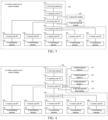
- the present disclosure discloses a digital optical fiber-based distributed signal control system, mainly including a wireless signal access control module 300, a detection module 100 and a private network module 200.
- the wireless signal access control module 300 mainly include a receiving antenna 310, a main control signal unit SU 320, a converged access unit AU 330, a remote unit RU 340, and a transmitting antenna 350 which are connected in sequence.
- the receiving antenna 310 receives a base station signal in the air from a base station.
- the main control signal unit SU 320 obtains the base station signal through a coaxial port, and obtains a baseband control signal corresponding to a communication signal at a frequency band after the base station signal is processed, wherein the baseband control signal after being encoded is transmitted through a digital optical fiber to the converged access unit AU 330 as a main control signal.
- the converged access unit AU 330 transmits the main control signal from the main control signal unit SU 320, a detecting signal from the detection module 100 and a private network signal from the private network module 200 to the remote unit RU 340 through the digital optical fiber.
- the remote unit RU 340 generates an auxiliary control signal according to a signal intensity of an access control area and base station information, mix the generated auxiliary control signal with the main control signal from the converged access unit AU 330 according to an algorithm to generate a preliminary control signal, filter out a signal with a frequency corresponding to the detecting and a signal with a frequency corresponding to the private network from the preliminary control signal to generate a comprehensive control signal through pre-selection filtering, and finally combine the comprehensive control signal with the detection signal and the private network signal to generate a comprehensive management signal.
- the transmitting antenna 350 transmits the comprehensive management signal from the remote unit RU 340 to the air to control transmitting a signal from the base station to a mobile phone.
- the detection module 100 includes at least one detecting base station 110 configured to detect an unauthorized mobile phone.
- the private network module 200 includes a private network base station 210 configured to provide private network communication for authorized users.
- the at least one detecting base station 110 and the private network base station 210 establish an uplink and downlink connection through the converged access unit AU 330, and the remote unit RU 340 in the wireless signal access control module 300 also serves as a forwarding relay for the detecting signal and the private network signal.
- the original design of the transmitting and receiving antennas in one in the original patented technology is changed, and the receiving antenna 310 is separated from the transmitting antenna 350.
- the antenna is connected to the main control signal unit SU 320 and the remote unit RU 340 respectively through a coaxial cable, digital optical fiber connections are adopted between the main control signal unit SU 320 and the converged access unit AU 330, and between the converged access unit AU 330 and the remote unit RU 340 or the like.
- the access control, detecting and private network functions of the present disclosure are integrated, and the principles of various functions are introduced below in combination with the present system.
- the wireless signal access control module 300 In order to detect an unauthorized mobile phone in the access control area and provide communication for mobile phones of authorized users, the wireless signal access control module 300 needs to work in cooperation with the detection module 100 and the private network module 200.
- the cooperation principle is the fact that in order to avoid an interference of the control signal on the detecting signal or an interference of the control signal on the private network signal, the comprehensive control signal, the detecting signal and the private network signal need have different frequencies.
- the frequency ranges of the private network base station 210 and the detecting base station 110 are different from the frequency ranges of the access control respectively and have no overlaps with the frequency ranges of the access control.
- the remote unit RU 340 may mix the generated auxiliary control signal with the main control signal from the converged access unit AU 330 according to the algorithm to generate a preliminary control signal, filter out a signal with a frequency corresponding to the detecting and a signal with a frequency corresponding to the private network from the preliminary control signal to generate a comprehensive control signal through pre-selection filtering, and finally combine the comprehensive control signal with the detecting signal and the private network signal to generate a comprehensive management signal.
- the uplink since there is no access control signal transmission, no interference will be caused to the detecting signal or the private network signal, and thus no special processing can be performed. It should be noted that, for the downlink, stray leakage of the comprehensive management signal of the downlink at the uplink frequency needs to be controlled.
- a plurality of remote units RUs are connected to the converged access unit AU 330 through the digital optical fiber and each remote unit RU 340 is connected to a transmitting antenna 350 through a coaxial cable.
- a plurality of remote units RUs are synchronously transmitting signals by control cooperation of the converged access unit AU 330 to achieve a larger access control area, a coverage of which can be extended from 10-200 meters to several kilometers required by the user.
- the distributed signal control system may further include an extension unit EU 360 connected to the converged access unit AU 330 and the remote unit RU 340 respectively through the digital optical fiber, and the extension unit EU 360 may act as an extension access to increase the number of ports of the remote unit RU 340. As mentioned above, adding the number of the remote unit RU 340 may achieve a larger range of control.
- the converged access unit AU 330 can be connected to a private base station and a plurality of detecting base stations 110 respectively.
- the corresponding number of detecting base stations 110 can be set according to the number of mobile operators in different countries. Take China as an example, since there are three main mobile operators in China, including Mobile, Unicom and Telecom, a detecting base station 110 can be set up for each mobile operator separately to reside unauthorized mobile phones from each mobile operator.
- FIG. 5 provides a schematic diagram of any one of the control systems.
- the main control signal unit SU 320 in the control system is further connected to a GPS antenna 500 to obtain synchronous GPS clock information and use a second flip time of the GPS as a common clock to realize synchronization among the plurality of control systems.
- the coverage area can be effectively expanded, and distributed coverage at kilometers level can be realized.
- the present disclosure may further include a positioning module 400 configured to obtain position information of a target mobile phone, and the positioning module 400 is connected to the detection module 100 and the converged access unit AU 330 respectively, detecting an intensity of an uplink signal of the target mobile phone in the positioning module 400 by match filtering according to an uplink signal characteristic of the target mobile phone, wherein a location of the target mobile phone is determined by identifying the positioning module 400 with the strongest signal strength among uplink signals.
- a positioning module 400 configured to obtain position information of a target mobile phone
- the positioning module 400 is connected to the detection module 100 and the converged access unit AU 330 respectively, detecting an intensity of an uplink signal of the target mobile phone in the positioning module 400 by match filtering according to an uplink signal characteristic of the target mobile phone, wherein a location of the target mobile phone is determined by identifying the positioning module 400 with the strongest signal strength among uplink signals.
Landscapes
- Engineering & Computer Science (AREA)
- Computer Networks & Wireless Communication (AREA)
- Signal Processing (AREA)
- Physics & Mathematics (AREA)
- Electromagnetism (AREA)
- Databases & Information Systems (AREA)
- Mobile Radio Communication Systems (AREA)
Claims (8)
- Digitales lichtwellenleiterbasiertes verteiltes Signalsteuersystem, umfassend ein Erkennungsmodul (100) und ein Privatnetzmodul (200), wobei das Erkennungsmodul (100) wenigstens eine erkennende Basisstation (110) umfasst, die dazu konfiguriert ist, ein nicht autorisiertes Mobiltelefon zu erkennen, und das Privatnetzmodul (200) eine Privatnetzbasisstation (210) umfasst, die dazu konfiguriert ist, private Netzkommunikation für autorisierte Benutzer bereitzustellen, dadurch gekennzeichnet, dass das System ferner ein Drahtlossignalzugangssteuermodul (300) umfasst, wobei das Drahtlossignalzugangssteuermodul (300) als Hauptbestandteile eine Empfangsantenne (310), eine Hauptsteuersignaleinheit SU (320), eine Einheit für konvergierten Zugang AU (330), eine Remote-Einheit RU (340) und eine Sendeantenne (350) umfasst, die nacheinander verbunden sind, wobei:die Empfangsantenne (310) dazu konfiguriert ist, ein Basisstationssignal in der Luft von einer Basisstation zu empfangen;wobei die Hauptsteuersignaleinheit SU (320) dazu konfiguriert ist, das Basisstationssignal durch einen Koaxialanschluss zu erlangen und ein Basisbandsteuersignal, das einem Kommunikationssignal entspricht, in einem Frequenzband zu erlangen, nachdem das Basisstationssignal verarbeitet wurde, wobei das Basisbandsteuersignal codiert und dann als Hauptsteuersignal durch einen digitalen Lichtwellenleiter an die Einheit für konvergierten Zugang AU (330) übertragen wird und der digitale Lichtwellenleiter dazu konfiguriert ist, ein Digitalsignal zu übertragen;wobei die Einheit für konvergierten Zugang AU (330) dazu konfiguriert ist, das Hauptsteuersignal von der Hauptsteuersignaleinheit SU (320), ein Erkennungssignal von dem Erkennungsmodul (100) und ein Privatnetzsignal von dem Privatnetzmodul (200) durch den digitalen Lichtwellenleiter an die Remote-Einheit RU (340) zu übertragen;wobei die Remote-Einheit RU (340) dazu konfiguriert ist, ein Hilfssteuersignal entsprechend einer Signalstärke eines Zugangssteuerbereichs und Basisstationsinformationen zu erzeugen, das erzeugte Hilfssteuersignal mit dem Hauptsteuersignal von der Einheit für konvergierten Zugang AU (340) gemäß einem Algorithmus zu mischen, um ein vorläufiges Steuersignal zu erzeugen, ein Signal mit einer Frequenz, die dem Erkennungssignal entspricht, und ein Signal mit einer Frequenz, die dem Privatnetzsignal entspricht, aus dem vorläufigen Steuersignal herauszufiltern, um durch Vorauswahlfilterung ein umfassendes Steuersignal zu erzeugen, und schließlich das umfassende Steuersignal mit dem Erkennungssignal und dem Privatnetzsignal zu kombinieren, um ein umfassendes Verwaltungssignal zu erzeugen;wobei die Sendeantenne (350) dazu konfiguriert ist, das umfassende Verwaltungssignal von der Remote-Einheit RU (340) an die Luft zu übertragen, um das Übertragen eines Signals von der Basisstation an ein Mobiltelefon zu steuern;wobei die wenigstens ein erkennende Basisstation (110) und die Privatnetzbasisstation (210) dazu konfiguriert sind, eine Uplink- und Downlink-Verbindung durch die Einheit für konvergierten Zugang AU (330) herzustellen, und die Remote-Einheit RU (340) in dem Drahtlossignalzugangssteuermodul (300) außerdem dazu konfiguriert ist, als ein Weiterleitungsrelais für das Erkennungssignal und das Privatnetzsignal zu dienen.
- Digitales lichtwellenleiterbasiertes verteiltes Signalsteuersystem nach Anspruch 1, dadurch gekennzeichnet, dass das Hauptsteuersignal mit P bezeichnet ist, das Hilfssteuersignal mit S bezeichnet ist und das vorläufige Steuersignal mit J bezeichnet ist und P und S gemäß dem Algorithmus gemischt werden, um J, J = α × P+(1-α) × S zu erzeugen, wobei 0 <α< 1, wenn α größer als 1, J = P ist, wobei α ein Verhältnis eines Radius einer Region, die tatsächlich durch die Remote-Einheit RU (340) abgedeckt wird, zu einer Entfernung zwischen der Remote-Einheit RU (340) und der Hauptsteuersignaleinheit SU (320) ist.
- Digitales lichtwellenleiterbasiertes verteiltes Signalsteuersystem nach Anspruch 1, dadurch gekennzeichnet, dass die Signale des Erkennungsmoduls (100), die Signale des Privatnetzmoduls (200) und die Signale des Drahtlossignalzugangssteuermoduls (300) unterschiedliche Frequenzen aufweisen.
- Digitales lichtwellenleiterbasiertes verteiltes Signalsteuersystem nach Anspruch 1, dadurch gekennzeichnet, dass die Remote-Einheit RU (340) in einer Anzahl von eins oder mehr vorliegt und wenigstens eine Remote-Einheit RU (340) durch den digitalen Lichtwellenleiter mit der Einheit für konvergierten Zugang AU (330) verbunden ist, wobei jede Remote-Einheit RU (340) durch ein Koaxialkabel mit einer oder mehreren Sendeantennen (350) verbunden ist.
- Digitales lichtwellenleiterbasiertes verteiltes Signalsteuersystem nach Anspruch 4, dadurch gekennzeichnet, dass das verteilte Signalsteuersystem ferner eine Erweiterungseinheit EU (360) umfasst, die durch den digitalen Lichtwellenleiter jeweils mit der Einheit für konvergierten Zugang AU (330) und der Remote-Einheit RU (340) verbunden ist, und die Erweiterungseinheit EU (360) dazu konfiguriert ist, als ein Erweiterungszugang zu dienen, und die Anzahl der Anschlüsse der Remote-Einheit RU (340) erhöht.
- Digitales lichtwellenleiterbasiertes verteiltes Signalsteuersystem nach Anspruch 1, dadurch gekennzeichnet, dass die Einheit für konvergierten Zugang AU (330) jeweils mit der Privatnetzbasisstation (210) und einer Vielzahl von erkennenden Basisstationen (110) verbunden ist, wobei die Anzahl der erkennenden Basisstationen (110) mit der Anzahl örtlicher Mobilfunkanbieter übereinstimmt.
- Digitales lichtwellenleiterbasiertes verteiltes Signalsteuersystem nach Anspruch 1, dadurch gekennzeichnet, dass das verteilte Signalsteuersystem ferner ein Positionsbestimmungsmodul (400) umfasst, das dazu konfiguriert ist, Positionsinformationen eines Zielmobiltelefons zu erlangen, und das Positionsbestimmungsmodul (400) jeweils mit dem Erkennungsmodul (100) und der Einheit für konvergierten Zugang AU (330) verbunden ist und eine Stärke eines Uplink-Signals des Zielmobiltelefons in dem Positionsbestimmungsmodul (400) durch Übereinstimmungsfilterung gemäß einer Uplink-Signalkennlinie des Zielmobiltelefons erkannt wird, wobei eine Position des Zielmobiltelefons durch Identifizieren des Positionsbestimmungsmoduls (400) mit der größten Signalstärke unter den Uplink-Signalen bestimmt wird.
- Digitales lichtwellenleiterbasiertes verteiltes Signalsteuersystem nach Anspruch 1, dadurch gekennzeichnet, dass das Steuersystem in einer Anzahl von eins oder mehr vorliegt und die Hauptsteuersignaleinheit SU (320) in jedem Steuersystem ferner mit einer GPS-Antenne (500) verbunden ist, um synchrone GPS-Taktinformationen zu erlangen und eine zweite Flip-Zeit des GPS als einen gemeinsamen Taktgeber zu verwenden, um Synchronisation unter einer Vielzahl von Steuersystemen zu erreichen.
Applications Claiming Priority (2)
| Application Number | Priority Date | Filing Date | Title |
|---|---|---|---|
| CN201810973130.1A CN109274428B (zh) | 2018-08-24 | 2018-08-24 | 一种数字光纤分布式信号管控系统 |
| PCT/CN2018/124741 WO2020037928A1 (zh) | 2018-08-24 | 2018-12-28 | 一种数字光纤分布式信号管控系统 |
Publications (3)
| Publication Number | Publication Date |
|---|---|
| EP3829083A1 EP3829083A1 (de) | 2021-06-02 |
| EP3829083A4 EP3829083A4 (de) | 2021-10-06 |
| EP3829083B1 true EP3829083B1 (de) | 2023-10-18 |
Family
ID=65154356
Family Applications (1)
| Application Number | Title | Priority Date | Filing Date |
|---|---|---|---|
| EP18931136.8A Active EP3829083B1 (de) | 2018-08-24 | 2018-12-28 | Auf digitaler optischer faser basierendes verteiltes signalsteuersystem |
Country Status (6)
| Country | Link |
|---|---|
| US (1) | US11438067B2 (de) |
| EP (1) | EP3829083B1 (de) |
| CN (1) | CN109274428B (de) |
| AU (1) | AU2018437534B2 (de) |
| CA (1) | CA3110420C (de) |
| WO (1) | WO2020037928A1 (de) |
Families Citing this family (2)
| Publication number | Priority date | Publication date | Assignee | Title |
|---|---|---|---|---|
| CN114828029B (zh) * | 2022-05-23 | 2025-06-24 | 大连市共进科技有限公司 | 分布式通信单元和通信扩展装置 |
| CN117202208A (zh) * | 2023-10-09 | 2023-12-08 | 阳新弘盛铜业有限公司 | 一种工厂非工业区无线组网布置方法 |
Family Cites Families (16)
| Publication number | Priority date | Publication date | Assignee | Title |
|---|---|---|---|---|
| JP3851554B2 (ja) | 2001-12-11 | 2006-11-29 | 株式会社日立製作所 | 携帯電話装置を制御する制御方法 |
| JP2004312150A (ja) * | 2003-04-03 | 2004-11-04 | Nippon Telegr & Teleph Corp <Ntt> | ディジタルファイバ無線伝送システム |
| CN101754431B (zh) | 2008-12-01 | 2012-07-04 | 中国移动通信集团天津有限公司 | 无线专用网络系统、设备及信号传输和切换方法 |
| US9673904B2 (en) * | 2009-02-03 | 2017-06-06 | Corning Optical Communications LLC | Optical fiber-based distributed antenna systems, components, and related methods for calibration thereof |
| AU2010210766A1 (en) * | 2009-02-03 | 2011-09-15 | Corning Cable Systems Llc | Optical fiber-based distributed antenna systems, components, and related methods for monitoring and configuring thereof |
| CN201528431U (zh) * | 2009-09-23 | 2010-07-14 | 京信通信系统(中国)有限公司 | 基于远端一体化模块的cdma数字光纤直放站系统 |
| US20110310941A1 (en) * | 2010-06-17 | 2011-12-22 | Peter Kenington | Remotely located radio transceiver for mobile communications network |
| CN101977081A (zh) * | 2010-10-26 | 2011-02-16 | 三维通信股份有限公司 | 一种高效率的数字光纤cdma直放站及实现方法 |
| EP2749123B1 (de) * | 2011-09-02 | 2022-03-30 | Dali Systems Co. Ltd. | Software-konfigurierbares verteiltes antennensystem und verfahren zur unterdrückung von uplink-geräuschen dafür |
| CN102412907A (zh) * | 2011-12-07 | 2012-04-11 | 奥维通信股份有限公司 | 多制式网络融合的数字光纤拉远系统 |
| CN103117909B (zh) * | 2012-12-26 | 2015-08-26 | 中邮科通信技术股份有限公司 | 一种多制式数字光纤五类线分布系统 |
| CN203387508U (zh) * | 2013-07-17 | 2014-01-08 | 三维通信股份有限公司 | 新型的多网融合室内分布系统 |
| CA3017856A1 (en) * | 2014-09-23 | 2016-03-31 | Axell Wireless Ltd. | Automatic mapping and handling pim and other uplink interferences in digital distributed antenna systems |
| US9769666B2 (en) * | 2015-09-25 | 2017-09-19 | Harris Corporation | Managed access system with monitoring device to determine and change radio equipment |
| CN107332639B (zh) * | 2017-06-12 | 2020-01-14 | 京信通信系统(中国)有限公司 | 一种专网通信的实现方法及系统 |
| CN208768072U (zh) * | 2018-08-24 | 2019-04-19 | 浙江三维通信科技有限公司 | 数字光纤分布式信号管控系统 |
-
2018
- 2018-08-24 CN CN201810973130.1A patent/CN109274428B/zh active Active
- 2018-12-28 AU AU2018437534A patent/AU2018437534B2/en active Active
- 2018-12-28 WO PCT/CN2018/124741 patent/WO2020037928A1/zh not_active Ceased
- 2018-12-28 EP EP18931136.8A patent/EP3829083B1/de active Active
- 2018-12-28 CA CA3110420A patent/CA3110420C/en active Active
- 2018-12-28 US US17/270,033 patent/US11438067B2/en active Active
Also Published As
| Publication number | Publication date |
|---|---|
| EP3829083A1 (de) | 2021-06-02 |
| US20210328672A1 (en) | 2021-10-21 |
| AU2018437534A1 (en) | 2021-03-25 |
| CA3110420A1 (en) | 2020-02-27 |
| WO2020037928A1 (zh) | 2020-02-27 |
| US11438067B2 (en) | 2022-09-06 |
| AU2018437534B2 (en) | 2022-06-30 |
| CA3110420C (en) | 2023-05-23 |
| CN109274428A (zh) | 2019-01-25 |
| EP3829083A4 (de) | 2021-10-06 |
| CN109274428B (zh) | 2024-06-04 |
Similar Documents
| Publication | Publication Date | Title |
|---|---|---|
| US5535259A (en) | Radio personal communications system and method for allocating frequencies for communications between a cellular terminal and a base station | |
| US7272362B2 (en) | Multi-sector in-building repeater | |
| US8750903B1 (en) | Cell phone control and localization for restricted facilities | |
| US20020197990A1 (en) | Signal Translating repeater for enabling a terrestrial mobile subscriber station to be operable in a non-terrestrial environment | |
| CN107332639B (zh) | 一种专网通信的实现方法及系统 | |
| CN107342838B (zh) | 一种专网通信的实现方法及系统 | |
| US6804540B1 (en) | Remote band-pass filter in a distributed antenna system | |
| GB2589036A (en) | Wireless communication systems for mitigating inter-and-intra-mobile device interference between communication sessions | |
| US6230008B1 (en) | Dual fixed/mobile communications system | |
| CA3110420C (en) | Digital optical fiber-based distributed signal control system | |
| JPH09186620A (ja) | 通信用機器および通信方法 | |
| US20100136983A1 (en) | Method of using available mobile communication terminal as relay station | |
| CN112600595B (zh) | 一种隧道漏缆通信系统 | |
| JPS5927636A (ja) | 無線通信方式 | |
| CN208768072U (zh) | 数字光纤分布式信号管控系统 | |
| CN112713959A (zh) | 5g终端屏蔽系统及方法 | |
| EP2499854A1 (de) | Identitätserfassung von mobilstationen in einem mobilen telekommunikationsnetz | |
| CN203942528U (zh) | 一种无线覆盖增强设备 | |
| KR20120105910A (ko) | 지휘통신무선망 시스템 및 그에 사용되는 듀얼모드 단말기 | |
| US20120165003A1 (en) | Wireless communications device | |
| RU123275U1 (ru) | Устройство выборочного блокирования мобильных телефонов | |
| KR100719613B1 (ko) | 릴레이 통신 장치, 릴레이 통신 장치의 통신 방법 및릴레이 통신 장치를 채용한 이동 통신 시스템 | |
| CN106411330A (zh) | 一种微波宽带多信道接收机 | |
| JPH08265840A (ja) | 移動無線通信システム | |
| CN101795503A (zh) | 一种升级现有无线通信基站、实现3g无缝覆盖的方法 |
Legal Events
| Date | Code | Title | Description |
|---|---|---|---|
| STAA | Information on the status of an ep patent application or granted ep patent |
Free format text: STATUS: THE INTERNATIONAL PUBLICATION HAS BEEN MADE |
|
| PUAI | Public reference made under article 153(3) epc to a published international application that has entered the european phase |
Free format text: ORIGINAL CODE: 0009012 |
|
| STAA | Information on the status of an ep patent application or granted ep patent |
Free format text: STATUS: REQUEST FOR EXAMINATION WAS MADE |
|
| 17P | Request for examination filed |
Effective date: 20210225 |
|
| AK | Designated contracting states |
Kind code of ref document: A1 Designated state(s): AL AT BE BG CH CY CZ DE DK EE ES FI FR GB GR HR HU IE IS IT LI LT LU LV MC MK MT NL NO PL PT RO RS SE SI SK SM TR |
|
| A4 | Supplementary search report drawn up and despatched |
Effective date: 20210903 |
|
| RIC1 | Information provided on ipc code assigned before grant |
Ipc: H04W 88/08 20090101ALI20210830BHEP Ipc: H04B 10/2575 20130101AFI20210830BHEP |
|
| DAV | Request for validation of the european patent (deleted) | ||
| DAX | Request for extension of the european patent (deleted) | ||
| GRAP | Despatch of communication of intention to grant a patent |
Free format text: ORIGINAL CODE: EPIDOSNIGR1 |
|
| STAA | Information on the status of an ep patent application or granted ep patent |
Free format text: STATUS: GRANT OF PATENT IS INTENDED |
|
| RIC1 | Information provided on ipc code assigned before grant |
Ipc: H04W 88/08 20090101ALI20230425BHEP Ipc: H04B 10/2575 20130101AFI20230425BHEP |
|
| INTG | Intention to grant announced |
Effective date: 20230517 |
|
| GRAS | Grant fee paid |
Free format text: ORIGINAL CODE: EPIDOSNIGR3 |
|
| GRAA | (expected) grant |
Free format text: ORIGINAL CODE: 0009210 |
|
| STAA | Information on the status of an ep patent application or granted ep patent |
Free format text: STATUS: THE PATENT HAS BEEN GRANTED |
|
| AK | Designated contracting states |
Kind code of ref document: B1 Designated state(s): AL AT BE BG CH CY CZ DE DK EE ES FI FR GB GR HR HU IE IS IT LI LT LU LV MC MK MT NL NO PL PT RO RS SE SI SK SM TR |
|
| REG | Reference to a national code |
Ref country code: GB Ref legal event code: FG4D |
|
| REG | Reference to a national code |
Ref country code: CH Ref legal event code: EP |
|
| REG | Reference to a national code |
Ref country code: DE Ref legal event code: R096 Ref document number: 602018059787 Country of ref document: DE |
|
| REG | Reference to a national code |
Ref country code: IE Ref legal event code: FG4D |
|
| REG | Reference to a national code |
Ref country code: LT Ref legal event code: MG9D |
|
| REG | Reference to a national code |
Ref country code: NL Ref legal event code: MP Effective date: 20231018 |
|
| REG | Reference to a national code |
Ref country code: AT Ref legal event code: MK05 Ref document number: 1623406 Country of ref document: AT Kind code of ref document: T Effective date: 20231018 |
|
| PG25 | Lapsed in a contracting state [announced via postgrant information from national office to epo] |
Ref country code: NL Free format text: LAPSE BECAUSE OF FAILURE TO SUBMIT A TRANSLATION OF THE DESCRIPTION OR TO PAY THE FEE WITHIN THE PRESCRIBED TIME-LIMIT Effective date: 20231018 |
|
| PG25 | Lapsed in a contracting state [announced via postgrant information from national office to epo] |
Ref country code: GR Free format text: LAPSE BECAUSE OF FAILURE TO SUBMIT A TRANSLATION OF THE DESCRIPTION OR TO PAY THE FEE WITHIN THE PRESCRIBED TIME-LIMIT Effective date: 20240119 |
|
| PG25 | Lapsed in a contracting state [announced via postgrant information from national office to epo] |
Ref country code: IS Free format text: LAPSE BECAUSE OF FAILURE TO SUBMIT A TRANSLATION OF THE DESCRIPTION OR TO PAY THE FEE WITHIN THE PRESCRIBED TIME-LIMIT Effective date: 20240218 |
|
| PG25 | Lapsed in a contracting state [announced via postgrant information from national office to epo] |
Ref country code: LT Free format text: LAPSE BECAUSE OF FAILURE TO SUBMIT A TRANSLATION OF THE DESCRIPTION OR TO PAY THE FEE WITHIN THE PRESCRIBED TIME-LIMIT Effective date: 20231018 |
|
| PG25 | Lapsed in a contracting state [announced via postgrant information from national office to epo] |
Ref country code: AT Free format text: LAPSE BECAUSE OF FAILURE TO SUBMIT A TRANSLATION OF THE DESCRIPTION OR TO PAY THE FEE WITHIN THE PRESCRIBED TIME-LIMIT Effective date: 20231018 |
|
| PG25 | Lapsed in a contracting state [announced via postgrant information from national office to epo] |
Ref country code: ES Free format text: LAPSE BECAUSE OF FAILURE TO SUBMIT A TRANSLATION OF THE DESCRIPTION OR TO PAY THE FEE WITHIN THE PRESCRIBED TIME-LIMIT Effective date: 20231018 |
|
| PG25 | Lapsed in a contracting state [announced via postgrant information from national office to epo] |
Ref country code: LT Free format text: LAPSE BECAUSE OF FAILURE TO SUBMIT A TRANSLATION OF THE DESCRIPTION OR TO PAY THE FEE WITHIN THE PRESCRIBED TIME-LIMIT Effective date: 20231018 Ref country code: IS Free format text: LAPSE BECAUSE OF FAILURE TO SUBMIT A TRANSLATION OF THE DESCRIPTION OR TO PAY THE FEE WITHIN THE PRESCRIBED TIME-LIMIT Effective date: 20240218 Ref country code: GR Free format text: LAPSE BECAUSE OF FAILURE TO SUBMIT A TRANSLATION OF THE DESCRIPTION OR TO PAY THE FEE WITHIN THE PRESCRIBED TIME-LIMIT Effective date: 20240119 Ref country code: ES Free format text: LAPSE BECAUSE OF FAILURE TO SUBMIT A TRANSLATION OF THE DESCRIPTION OR TO PAY THE FEE WITHIN THE PRESCRIBED TIME-LIMIT Effective date: 20231018 Ref country code: BG Free format text: LAPSE BECAUSE OF FAILURE TO SUBMIT A TRANSLATION OF THE DESCRIPTION OR TO PAY THE FEE WITHIN THE PRESCRIBED TIME-LIMIT Effective date: 20240118 Ref country code: AT Free format text: LAPSE BECAUSE OF FAILURE TO SUBMIT A TRANSLATION OF THE DESCRIPTION OR TO PAY THE FEE WITHIN THE PRESCRIBED TIME-LIMIT Effective date: 20231018 Ref country code: PT Free format text: LAPSE BECAUSE OF FAILURE TO SUBMIT A TRANSLATION OF THE DESCRIPTION OR TO PAY THE FEE WITHIN THE PRESCRIBED TIME-LIMIT Effective date: 20240219 |
|
| PG25 | Lapsed in a contracting state [announced via postgrant information from national office to epo] |
Ref country code: SE Free format text: LAPSE BECAUSE OF FAILURE TO SUBMIT A TRANSLATION OF THE DESCRIPTION OR TO PAY THE FEE WITHIN THE PRESCRIBED TIME-LIMIT Effective date: 20231018 Ref country code: RS Free format text: LAPSE BECAUSE OF FAILURE TO SUBMIT A TRANSLATION OF THE DESCRIPTION OR TO PAY THE FEE WITHIN THE PRESCRIBED TIME-LIMIT Effective date: 20231018 Ref country code: PL Free format text: LAPSE BECAUSE OF FAILURE TO SUBMIT A TRANSLATION OF THE DESCRIPTION OR TO PAY THE FEE WITHIN THE PRESCRIBED TIME-LIMIT Effective date: 20231018 Ref country code: NO Free format text: LAPSE BECAUSE OF FAILURE TO SUBMIT A TRANSLATION OF THE DESCRIPTION OR TO PAY THE FEE WITHIN THE PRESCRIBED TIME-LIMIT Effective date: 20240118 Ref country code: LV Free format text: LAPSE BECAUSE OF FAILURE TO SUBMIT A TRANSLATION OF THE DESCRIPTION OR TO PAY THE FEE WITHIN THE PRESCRIBED TIME-LIMIT Effective date: 20231018 Ref country code: HR Free format text: LAPSE BECAUSE OF FAILURE TO SUBMIT A TRANSLATION OF THE DESCRIPTION OR TO PAY THE FEE WITHIN THE PRESCRIBED TIME-LIMIT Effective date: 20231018 |
|
| REG | Reference to a national code |
Ref country code: DE Ref legal event code: R119 Ref document number: 602018059787 Country of ref document: DE |
|
| PG25 | Lapsed in a contracting state [announced via postgrant information from national office to epo] |
Ref country code: DK Free format text: LAPSE BECAUSE OF FAILURE TO SUBMIT A TRANSLATION OF THE DESCRIPTION OR TO PAY THE FEE WITHIN THE PRESCRIBED TIME-LIMIT Effective date: 20231018 |
|
| PG25 | Lapsed in a contracting state [announced via postgrant information from national office to epo] |
Ref country code: CZ Free format text: LAPSE BECAUSE OF FAILURE TO SUBMIT A TRANSLATION OF THE DESCRIPTION OR TO PAY THE FEE WITHIN THE PRESCRIBED TIME-LIMIT Effective date: 20231018 |
|
| PG25 | Lapsed in a contracting state [announced via postgrant information from national office to epo] |
Ref country code: SK Free format text: LAPSE BECAUSE OF FAILURE TO SUBMIT A TRANSLATION OF THE DESCRIPTION OR TO PAY THE FEE WITHIN THE PRESCRIBED TIME-LIMIT Effective date: 20231018 |
|
| PG25 | Lapsed in a contracting state [announced via postgrant information from national office to epo] |
Ref country code: SM Free format text: LAPSE BECAUSE OF FAILURE TO SUBMIT A TRANSLATION OF THE DESCRIPTION OR TO PAY THE FEE WITHIN THE PRESCRIBED TIME-LIMIT Effective date: 20231018 Ref country code: SK Free format text: LAPSE BECAUSE OF FAILURE TO SUBMIT A TRANSLATION OF THE DESCRIPTION OR TO PAY THE FEE WITHIN THE PRESCRIBED TIME-LIMIT Effective date: 20231018 Ref country code: RO Free format text: LAPSE BECAUSE OF FAILURE TO SUBMIT A TRANSLATION OF THE DESCRIPTION OR TO PAY THE FEE WITHIN THE PRESCRIBED TIME-LIMIT Effective date: 20231018 Ref country code: IT Free format text: LAPSE BECAUSE OF FAILURE TO SUBMIT A TRANSLATION OF THE DESCRIPTION OR TO PAY THE FEE WITHIN THE PRESCRIBED TIME-LIMIT Effective date: 20231018 Ref country code: EE Free format text: LAPSE BECAUSE OF FAILURE TO SUBMIT A TRANSLATION OF THE DESCRIPTION OR TO PAY THE FEE WITHIN THE PRESCRIBED TIME-LIMIT Effective date: 20231018 Ref country code: DK Free format text: LAPSE BECAUSE OF FAILURE TO SUBMIT A TRANSLATION OF THE DESCRIPTION OR TO PAY THE FEE WITHIN THE PRESCRIBED TIME-LIMIT Effective date: 20231018 Ref country code: CZ Free format text: LAPSE BECAUSE OF FAILURE TO SUBMIT A TRANSLATION OF THE DESCRIPTION OR TO PAY THE FEE WITHIN THE PRESCRIBED TIME-LIMIT Effective date: 20231018 |
|
| REG | Reference to a national code |
Ref country code: CH Ref legal event code: PL |
|
| PLBE | No opposition filed within time limit |
Free format text: ORIGINAL CODE: 0009261 |
|
| STAA | Information on the status of an ep patent application or granted ep patent |
Free format text: STATUS: NO OPPOSITION FILED WITHIN TIME LIMIT |
|
| PG25 | Lapsed in a contracting state [announced via postgrant information from national office to epo] |
Ref country code: LU Free format text: LAPSE BECAUSE OF NON-PAYMENT OF DUE FEES Effective date: 20231228 |
|
| PG25 | Lapsed in a contracting state [announced via postgrant information from national office to epo] |
Ref country code: MC Free format text: LAPSE BECAUSE OF FAILURE TO SUBMIT A TRANSLATION OF THE DESCRIPTION OR TO PAY THE FEE WITHIN THE PRESCRIBED TIME-LIMIT Effective date: 20231018 |
|
| REG | Reference to a national code |
Ref country code: BE Ref legal event code: MM Effective date: 20231231 |
|
| PG25 | Lapsed in a contracting state [announced via postgrant information from national office to epo] |
Ref country code: MC Free format text: LAPSE BECAUSE OF FAILURE TO SUBMIT A TRANSLATION OF THE DESCRIPTION OR TO PAY THE FEE WITHIN THE PRESCRIBED TIME-LIMIT Effective date: 20231018 Ref country code: LU Free format text: LAPSE BECAUSE OF NON-PAYMENT OF DUE FEES Effective date: 20231228 |
|
| 26N | No opposition filed |
Effective date: 20240719 |
|
| REG | Reference to a national code |
Ref country code: IE Ref legal event code: MM4A |
|
| PG25 | Lapsed in a contracting state [announced via postgrant information from national office to epo] |
Ref country code: DE Free format text: LAPSE BECAUSE OF NON-PAYMENT OF DUE FEES Effective date: 20240702 Ref country code: IE Free format text: LAPSE BECAUSE OF NON-PAYMENT OF DUE FEES Effective date: 20231228 |
|
| PG25 | Lapsed in a contracting state [announced via postgrant information from national office to epo] |
Ref country code: BE Free format text: LAPSE BECAUSE OF NON-PAYMENT OF DUE FEES Effective date: 20231231 |
|
| PG25 | Lapsed in a contracting state [announced via postgrant information from national office to epo] |
Ref country code: CH Free format text: LAPSE BECAUSE OF NON-PAYMENT OF DUE FEES Effective date: 20231231 |
|
| PG25 | Lapsed in a contracting state [announced via postgrant information from national office to epo] |
Ref country code: SI Free format text: LAPSE BECAUSE OF FAILURE TO SUBMIT A TRANSLATION OF THE DESCRIPTION OR TO PAY THE FEE WITHIN THE PRESCRIBED TIME-LIMIT Effective date: 20231018 |
|
| PG25 | Lapsed in a contracting state [announced via postgrant information from national office to epo] |
Ref country code: SI Free format text: LAPSE BECAUSE OF FAILURE TO SUBMIT A TRANSLATION OF THE DESCRIPTION OR TO PAY THE FEE WITHIN THE PRESCRIBED TIME-LIMIT Effective date: 20231018 Ref country code: IE Free format text: LAPSE BECAUSE OF NON-PAYMENT OF DUE FEES Effective date: 20231228 Ref country code: DE Free format text: LAPSE BECAUSE OF NON-PAYMENT OF DUE FEES Effective date: 20240702 Ref country code: CH Free format text: LAPSE BECAUSE OF NON-PAYMENT OF DUE FEES Effective date: 20231231 Ref country code: BE Free format text: LAPSE BECAUSE OF NON-PAYMENT OF DUE FEES Effective date: 20231231 |
|
| PG25 | Lapsed in a contracting state [announced via postgrant information from national office to epo] |
Ref country code: FI Free format text: LAPSE BECAUSE OF FAILURE TO SUBMIT A TRANSLATION OF THE DESCRIPTION OR TO PAY THE FEE WITHIN THE PRESCRIBED TIME-LIMIT Effective date: 20231019 |
|
| PG25 | Lapsed in a contracting state [announced via postgrant information from national office to epo] |
Ref country code: CY Free format text: LAPSE BECAUSE OF FAILURE TO SUBMIT A TRANSLATION OF THE DESCRIPTION OR TO PAY THE FEE WITHIN THE PRESCRIBED TIME-LIMIT; INVALID AB INITIO Effective date: 20181228 |
|
| PG25 | Lapsed in a contracting state [announced via postgrant information from national office to epo] |
Ref country code: HU Free format text: LAPSE BECAUSE OF FAILURE TO SUBMIT A TRANSLATION OF THE DESCRIPTION OR TO PAY THE FEE WITHIN THE PRESCRIBED TIME-LIMIT; INVALID AB INITIO Effective date: 20181228 |
|
| PG25 | Lapsed in a contracting state [announced via postgrant information from national office to epo] |
Ref country code: TR Free format text: LAPSE BECAUSE OF FAILURE TO SUBMIT A TRANSLATION OF THE DESCRIPTION OR TO PAY THE FEE WITHIN THE PRESCRIBED TIME-LIMIT Effective date: 20231018 |
|
| PGFP | Annual fee paid to national office [announced via postgrant information from national office to epo] |
Ref country code: GB Payment date: 20251121 Year of fee payment: 8 |
|
| PGFP | Annual fee paid to national office [announced via postgrant information from national office to epo] |
Ref country code: FR Payment date: 20251120 Year of fee payment: 8 |