EP3829013A1 - Cable duct - Google Patents
Cable duct Download PDFInfo
- Publication number
- EP3829013A1 EP3829013A1 EP19211564.0A EP19211564A EP3829013A1 EP 3829013 A1 EP3829013 A1 EP 3829013A1 EP 19211564 A EP19211564 A EP 19211564A EP 3829013 A1 EP3829013 A1 EP 3829013A1
- Authority
- EP
- European Patent Office
- Prior art keywords
- holder
- cable duct
- cable
- support portion
- engaging element
- Prior art date
- Legal status (The legal status is an assumption and is not a legal conclusion. Google has not performed a legal analysis and makes no representation as to the accuracy of the status listed.)
- Withdrawn
Links
Images

Classifications
-
- H—ELECTRICITY
- H02—GENERATION; CONVERSION OR DISTRIBUTION OF ELECTRIC POWER
- H02G—INSTALLATION OF ELECTRIC CABLES OR LINES, OR OF COMBINED OPTICAL AND ELECTRIC CABLES OR LINES
- H02G3/00—Installations of electric cables or lines or protective tubing therefor in or on buildings, equivalent structures or vehicles
- H02G3/02—Details
- H02G3/04—Protective tubing or conduits, e.g. cable ladders or cable troughs
- H02G3/0437—Channels
-
- B—PERFORMING OPERATIONS; TRANSPORTING
- B60—VEHICLES IN GENERAL
- B60Q—ARRANGEMENT OF SIGNALLING OR LIGHTING DEVICES, THE MOUNTING OR SUPPORTING THEREOF OR CIRCUITS THEREFOR, FOR VEHICLES IN GENERAL
- B60Q1/00—Arrangement of optical signalling or lighting devices, the mounting or supporting thereof or circuits therefor
- B60Q1/0088—Details of electrical connections
-
- B—PERFORMING OPERATIONS; TRANSPORTING
- B60—VEHICLES IN GENERAL
- B60R—VEHICLES, VEHICLE FITTINGS, OR VEHICLE PARTS, NOT OTHERWISE PROVIDED FOR
- B60R16/00—Electric or fluid circuits specially adapted for vehicles and not otherwise provided for; Arrangement of elements of electric or fluid circuits specially adapted for vehicles and not otherwise provided for
- B60R16/02—Electric or fluid circuits specially adapted for vehicles and not otherwise provided for; Arrangement of elements of electric or fluid circuits specially adapted for vehicles and not otherwise provided for electric constitutive elements
- B60R16/0207—Wire harnesses
- B60R16/0215—Protecting, fastening and routing means therefor
-
- H—ELECTRICITY
- H02—GENERATION; CONVERSION OR DISTRIBUTION OF ELECTRIC POWER
- H02G—INSTALLATION OF ELECTRIC CABLES OR LINES, OR OF COMBINED OPTICAL AND ELECTRIC CABLES OR LINES
- H02G3/00—Installations of electric cables or lines or protective tubing therefor in or on buildings, equivalent structures or vehicles
- H02G3/02—Details
- H02G3/06—Joints for connecting lengths of protective tubing or channels, to each other or to casings, e.g. to distribution boxes; Ensuring electrical continuity in the joint
- H02G3/0608—Joints for connecting non cylindrical conduits, e.g. channels
-
- F—MECHANICAL ENGINEERING; LIGHTING; HEATING; WEAPONS; BLASTING
- F21—LIGHTING
- F21S—NON-PORTABLE LIGHTING DEVICES; SYSTEMS THEREOF; VEHICLE LIGHTING DEVICES SPECIALLY ADAPTED FOR VEHICLE EXTERIORS
- F21S45/00—Arrangements within vehicle lighting devices specially adapted for vehicle exteriors, for purposes other than emission or distribution of light
-
- H—ELECTRICITY
- H02—GENERATION; CONVERSION OR DISTRIBUTION OF ELECTRIC POWER
- H02G—INSTALLATION OF ELECTRIC CABLES OR LINES, OR OF COMBINED OPTICAL AND ELECTRIC CABLES OR LINES
- H02G3/00—Installations of electric cables or lines or protective tubing therefor in or on buildings, equivalent structures or vehicles
- H02G3/02—Details
- H02G3/04—Protective tubing or conduits, e.g. cable ladders or cable troughs
- H02G3/0406—Details thereof
- H02G3/0418—Covers or lids; Their fastenings
Definitions
- the invention relates to a cable duct for holding at least one cable, comprising a cable guiding portion configured to guide the at least one cable in a determined position.
- the invention also relates to a vehicle headlamp with at least one cable duct according to the invention.
- a cable duct for holding or guiding cables of a control unit and the control unit itself are mounted and assembled separately into a housing of the vehicle headlamp. This has the effect that an assembly of both parts is difficult due to the restriction of space in a housing of a vehicle headlamp. Also, during a service of a vehicle headlamp, an additional part is necessary for fixation of the control unit.
- the cable guiding portion comprises a support portion with at least one first second engaging element
- the cable duct comprises a foldable holder for holding a housing of a control unit, which holder is pivotably connected to the cable guiding portion, wherein the holder comprises at least one second engaging element, wherein the holder can be brought into an end position on the support portion by folding the holder towards the support portion, such that the at least one first engaging element engages with the at least one second engaging element.
- the holder is also suitable to hold a PCB (printed circuit board), module, data bus or any electronic element.
- PCB printed circuit board
- the at least one first engaging element is built as a latching-element and the at least one second engaging element is built as a counter latching-element.
- the at least one first engaging element is built as a detent lug and the at least one second engaging element is built as a rigid leg, wherein the rigid led snaps in the detent lug, when the holder is in the end position.
- the holder comprises at least two second engaging elements, preferably exactly two second engaging elements.
- the support portion comprises at least two first engaging elements, preferably exactly two first engaging elements.
- the support portion comprises at least one protrusion configured to limit the folding of the holder towards the support portion, wherein the holder abuts on the at least one protrusion in the end position of the holder.
- the at least one second engaging element of the holder abuts on the at least one protrusion.
- the support portion comprises at least two protrusions, preferably exactly two protrusions.
- the holder is connected with the cable guiding portion by means of a hinge film.
- the holder is connected with the cable guiding portion by means of a rotary hinge.
- the cable duct is being made of an integral piece of material.
- integral piece can also be understood as “monolithic”.
- the cable duct is made of one material.
- the cable duct is made in a molding process.
- the object of the invention is also be achieved by a vehicle headlamp with at least one cable duct.
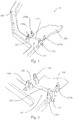
- Fig. 1 shows a cable duct 10 for a vehicle headlamp and for holding at least one cable, wherein the cable duct 10 comprises a cable guiding portion 100 configured to guide the at least one cable in a determined position.
- the cable guiding portion 100 comprises a support portion 110 with two first engaging elements 110a
- the cable duct 10 also comprises a foldable holder 200 for holding a housing of a control unit, which holder 200 is pivotably connected to the cable guiding portion 100 wherein the holder 200 comprises two second engaging elements 210a, each of which is assigned to one first engaging element 110a of the support portion 110.
- the two first engaging elements 110a are built as a detent lug and two second engaging elements 210a are built as a rigid leg, which can be seen in more detail in Fig. 2 .
- the holder 200 is connected with the cable duct 10, in particular with the support portion 110 of the cable duct 10, by means of a hinge film 220, wherein the cable duct 10 is built monolithic and is made of an integral piece of material in a moulding process.
- the holder 200 can be brought into an end position P1 on the support portion 110 by folding the holder 200 towards the support portion 110, such that the first engaging elements 110a engages with the at least one second engaging element 210a to secure the holder in the end position P1, in particular the second engaging elements 210a formed as rigid legs snap in the first engaging elements 110a formed as detent lugs, when the holder 200 is in the end position PI, which can be seen in Fig. 3 and more detailed in Fig. 4 .
- the support portion 110 comprises two protrusions 120, wherein the holder 200, in particular the second engaging elements 210a, abuts on the protrusions 120 in the end position PI, which can be clearly seen in Fig. 4 , wherein Fig. 4 also shows a mounted housing of a control unit 300 on the holder 200.
Abstract
Cable duct (10) for a vehicle headlamp and for holding at least one cable, comprising a cable guiding portion (100) configured to guide the at least one cable in a determined position, wherein the cable guiding portion (100) comprises a support portion (110) with at least one first engaging element (110a), wherein the cable duct (10) comprises a foldable holder (200) for holding a control unit, wherein the holder (200) comprises at least one second engaging element (210a), wherein the holder (200) can be brought into an end position (P1) on the support portion (110) by folding the holder (200) towards the support portion (110), such that the at least one first engaging element (110a) engages with the at least one second engaging element (210a) to secure the holder (200) in the end position (P1).
Description
- The invention relates to a cable duct for holding at least one cable, comprising a cable guiding portion configured to guide the at least one cable in a determined position.
- The invention also relates to a vehicle headlamp with at least one cable duct according to the invention.
- In current vehicle headlamps a cable duct for holding or guiding cables of a control unit and the control unit itself are mounted and assembled separately into a housing of the vehicle headlamp. This has the effect that an assembly of both parts is difficult due to the restriction of space in a housing of a vehicle headlamp. Also, during a service of a vehicle headlamp, an additional part is necessary for fixation of the control unit.
- This leads to a significant effort with regard to the assembling of the cable duct and the control unit in a desired position in a vehicle headlamp.
- It is an object of the invention to provide an enhanced cable duct.
- To achieve this object, the cable guiding portion comprises a support portion with at least one first second engaging element, wherein the cable duct comprises a foldable holder for holding a housing of a control unit, which holder is pivotably connected to the cable guiding portion, wherein the holder comprises at least one second engaging element, wherein the holder can be brought into an end position on the support portion by folding the holder towards the support portion, such that the at least one first engaging element engages with the at least one second engaging element.
- This allows the possibility to easy exchange the control unit during service in the housing, allows better balance for assembly operations, allows more flexibility of spacing of the control unit and allows easier assembly outside of the housing.
- It should be noted, that apart from a housing of a control unit, the holder is also suitable to hold a PCB (printed circuit board), module, data bus or any electronic element.
- Advantageously, the at least one first engaging element is built as a latching-element and the at least one second engaging element is built as a counter latching-element.
- Advantageously, the at least one first engaging element is built as a detent lug and the at least one second engaging element is built as a rigid leg, wherein the rigid led snaps in the detent lug, when the holder is in the end position.
- Advantageously, the holder comprises at least two second engaging elements, preferably exactly two second engaging elements.
- Advantageously, the support portion comprises at least two first engaging elements, preferably exactly two first engaging elements.
- Advantageously, the support portion comprises at least one protrusion configured to limit the folding of the holder towards the support portion, wherein the holder abuts on the at least one protrusion in the end position of the holder.
- This has the advantage, that the holder cannot be folded beyond the desired end position. This also prevents, that the holder is shaking during naturally occurring vibrations of the vehicle headlamp or vehicle, in which the vehicle headlamp and the cable duct is installed.
- Advantageously, the at least one second engaging element of the holder abuts on the at least one protrusion.
- Advantageously, the support portion comprises at least two protrusions, preferably exactly two protrusions.
- Advantageously, the holder is connected with the cable guiding portion by means of a hinge film.
- Advantageously, the holder is connected with the cable guiding portion by means of a rotary hinge.
- Advantageously, the cable duct is being made of an integral piece of material. The term "integral piece" can also be understood as "monolithic".
- Advantageously, the cable duct is made of one material.
- Advantageously, the cable duct is made in a molding process.
- The object of the invention is also be achieved by a vehicle headlamp with at least one cable duct.
- In the following, in order to further demonstrate the present invention, illustrative and non-restrictive embodiments are discussed, as shown in the drawings, which show:
- Fig. 1
- an example of a cable duct with a support portion comprising two first engaging elements, and a holder comprising two second engaging elements,
- Fig. 2
- a detailed view of the first and second engaging elements of the support portion and the holder,
- Fig. 3
- the cable duct of
Fig. 1 , wherein the holder is in an end position, - Fig. 4
- a detailed view of the end position of the holder, wherein the second engaging elements engage with the first engaging elements.
-
Fig. 1 shows acable duct 10 for a vehicle headlamp and for holding at least one cable, wherein thecable duct 10 comprises acable guiding portion 100 configured to guide the at least one cable in a determined position. - Further, the
cable guiding portion 100 comprises asupport portion 110 with two firstengaging elements 110a, wherein thecable duct 10 also comprises afoldable holder 200 for holding a housing of a control unit, whichholder 200 is pivotably connected to thecable guiding portion 100 wherein theholder 200 comprises two secondengaging elements 210a, each of which is assigned to one firstengaging element 110a of thesupport portion 110. In the shown example, the two firstengaging elements 110a are built as a detent lug and two secondengaging elements 210a are built as a rigid leg, which can be seen in more detail inFig. 2 . - The
holder 200 is connected with thecable duct 10, in particular with thesupport portion 110 of thecable duct 10, by means of ahinge film 220, wherein thecable duct 10 is built monolithic and is made of an integral piece of material in a moulding process. - The
holder 200 can be brought into an end position P1 on thesupport portion 110 by folding theholder 200 towards thesupport portion 110, such that the firstengaging elements 110a engages with the at least one secondengaging element 210a to secure the holder in the end position P1, in particular the secondengaging elements 210a formed as rigid legs snap in the firstengaging elements 110a formed as detent lugs, when theholder 200 is in the end position PI, which can be seen inFig. 3 and more detailed inFig. 4 . - In order to limit the folding of the
holder 200 towards thesupport portion 110, thesupport portion 110 comprises twoprotrusions 120, wherein theholder 200, in particular the secondengaging elements 210a, abuts on theprotrusions 120 in the end position PI, which can be clearly seen inFig. 4 , whereinFig. 4 also shows a mounted housing of acontrol unit 300 on theholder 200.LIST OF REFERENCE SIGNS Cable duct... 10 Cable guiding portion... 100 Support portion... 110 First engaging element... 110a Protrusion... 120 Holder... 200 Second engaging element... 210a Housing of a control unit... 300 End position... P1
Claims (14)
- Cable duct (10) for holding at least one cable, comprising a cable guiding portion (100) configured to guide the at least one cable in a determined position,
characterized in that
the cable guiding portion (100) comprises a support portion (110) with at least one first engaging element (110a), wherein the cable duct (10) comprises a foldable holder (200) for holding a housing of a control unit, which holder (200) is pivotably connected with the cable guiding portion (100), wherein the holder (200) comprises at least one second engaging element (210a), wherein the holder (200) can be brought into an end position (P1) on the support portion (110) by folding the holder (200) towards the support portion (110), such that the at least one first engaging element (110a) engages with the at least one second engaging element (210a) to secure the holder in the end position (P1). - Cable duct according to claim 1, wherein the at least one first engaging element (110a) is shaped as a latching-element and the at least one second engaging element (210a) is shaped as a counter latching-element.
- Cable duct according to claim 1 or 2, wherein the at least one first engaging element (110a) is built as a detent lug and the at least one second engaging element (210a) is built as a rigid leg, wherein the rigid leg snaps in the detent lug, when the holder (200) is in the end position (P1).
- Cable duct according to any of the claims 1 to 3, wherein the holder (200) comprises at least two second engaging elements (210a), preferably exactly two second engaging elements (210a).
- Cable duct according to any of the claims 1 to 4, wherein the support portion (110) comprises at least two first engaging elements (110a), preferably exactly two first engaging elements (110a).
- Cable duct according to any of the claims 1 to 5, wherein the support portion (110) comprises at least one protrusion (120) configured to limit the folding of the holder (200) towards the support portion (110), wherein the holder (200) abuts on the at least one protrusion (120) in the end position (P1) of the holder (200).
- Cable duct according to claim 6, wherein the at least one second engaging element (210a) of the holder (200) abuts on the at least one protrusion (120).
- Cable duct according to claims 6 or 7, wherein the support portion (110) comprises a least two protrusions (120), preferably exactly two protrusions (120).
- Cable duct according to any of the claims 1 to 8, wherein the holder (200) is connected with the cable guiding portion (100) by means of a hinge film (220).
- Cable duct according to any of the claims 1 to 8, wherein the holder (200) is connected with the cable guiding portion (100) by means of a rotary hinge.
- Cable duct according to any of the claims 1 to 10, wherein the cable duct (10) is being made of an integral piece of material.
- Cable duct according to claim 11, wherein the cable duct (10) is made of one material.
- Cable duct according to any of the claims 1 to 12, wherein the cable duct (10) is made in a moulding process.
- Vehicle headlamp with at least one cable duct (10) according to any of the claims 1 to 13.
Priority Applications (3)
| Application Number | Priority Date | Filing Date | Title |
|---|---|---|---|
| EP19211564.0A EP3829013A1 (en) | 2019-11-26 | 2019-11-26 | Cable duct |
| PCT/EP2020/079572 WO2021104759A1 (en) | 2019-11-26 | 2020-10-21 | Cable duct |
| DE212020000706.3U DE212020000706U1 (en) | 2019-11-26 | 2020-10-21 | grommet |
Applications Claiming Priority (1)
| Application Number | Priority Date | Filing Date | Title |
|---|---|---|---|
| EP19211564.0A EP3829013A1 (en) | 2019-11-26 | 2019-11-26 | Cable duct |
Publications (1)
| Publication Number | Publication Date |
|---|---|
| EP3829013A1 true EP3829013A1 (en) | 2021-06-02 |
Family
ID=68699183
Family Applications (1)
| Application Number | Title | Priority Date | Filing Date |
|---|---|---|---|
| EP19211564.0A Withdrawn EP3829013A1 (en) | 2019-11-26 | 2019-11-26 | Cable duct |
Country Status (3)
| Country | Link |
|---|---|
| EP (1) | EP3829013A1 (en) |
| DE (1) | DE212020000706U1 (en) |
| WO (1) | WO2021104759A1 (en) |
Citations (5)
| Publication number | Priority date | Publication date | Assignee | Title |
|---|---|---|---|---|
| GB2207561A (en) * | 1987-07-02 | 1989-02-01 | Yazaki Corp | Cable trunking |
| US20030159846A1 (en) * | 2002-02-22 | 2003-08-28 | Honda Giken Kogyo Kabushiki Kaisha | Protector for wire harnesses and mounting mechanism |
| EP2107655A2 (en) * | 2008-04-01 | 2009-10-07 | BSH Bosch und Siemens Hausgeräte GmbH | Cable holder |
| CN206358060U (en) * | 2016-12-08 | 2017-07-28 | 锦祥照明系统(大连)有限公司 | Vehicle head lamp |
| US20180316166A1 (en) * | 2017-04-28 | 2018-11-01 | Sumitomo Wiring Systems, Ltd. | Wire harness protector |
-
2019
- 2019-11-26 EP EP19211564.0A patent/EP3829013A1/en not_active Withdrawn
-
2020
- 2020-10-21 DE DE212020000706.3U patent/DE212020000706U1/en active Active
- 2020-10-21 WO PCT/EP2020/079572 patent/WO2021104759A1/en active Application Filing
Patent Citations (5)
| Publication number | Priority date | Publication date | Assignee | Title |
|---|---|---|---|---|
| GB2207561A (en) * | 1987-07-02 | 1989-02-01 | Yazaki Corp | Cable trunking |
| US20030159846A1 (en) * | 2002-02-22 | 2003-08-28 | Honda Giken Kogyo Kabushiki Kaisha | Protector for wire harnesses and mounting mechanism |
| EP2107655A2 (en) * | 2008-04-01 | 2009-10-07 | BSH Bosch und Siemens Hausgeräte GmbH | Cable holder |
| CN206358060U (en) * | 2016-12-08 | 2017-07-28 | 锦祥照明系统(大连)有限公司 | Vehicle head lamp |
| US20180316166A1 (en) * | 2017-04-28 | 2018-11-01 | Sumitomo Wiring Systems, Ltd. | Wire harness protector |
Also Published As
| Publication number | Publication date |
|---|---|
| WO2021104759A1 (en) | 2021-06-03 |
| DE212020000706U1 (en) | 2022-04-26 |
Similar Documents
| Publication | Publication Date | Title |
|---|---|---|
| JP5410041B2 (en) | Wiring board, electric seat, and wiring harness routing method | |
| US7699622B2 (en) | Electronic unit and assembling method thereof | |
| US7118390B2 (en) | Electric junction box | |
| US20080247146A1 (en) | Fixing System For Printed Circuit Boards | |
| US20220088998A1 (en) | Heating device | |
| EP3829013A1 (en) | Cable duct | |
| US8937813B2 (en) | Sub-rack mounting bracket and assembly | |
| CN103270651A (en) | Flexible device for electrically connecting an electric component and a printed circuit board together, system, and method for mounting a system | |
| US10541485B2 (en) | On-board diagnostic system and terminal and manufacturing method thereof | |
| KR20080105894A (en) | Sign board frame for vehicle | |
| JP2013064759A (en) | Thin display device | |
| EP2663170A2 (en) | Fastening means, fastening arrangement and method for establishing a fastening arrangement | |
| KR100934906B1 (en) | Junction Box | |
| JPH08250886A (en) | Electric board | |
| KR101974822B1 (en) | cooling module mounting bracket for automobile | |
| CN111163598A (en) | Assembly of an electronic device with a device housing and an electronic assembly | |
| US20070108859A1 (en) | Seat motors assembly | |
| KR101091946B1 (en) | Supporting jig for wire harness | |
| JP2008253040A (en) | Structure for installing live part protective cover | |
| JP2018129441A (en) | Electronic control device | |
| CN204887821U (en) | A installing support and electronic equipment for fixing PCBA | |
| JP2011040527A (en) | Power supply structure, and rack having the same | |
| JP3535654B2 (en) | Connector and its mounting structure | |
| KR100645582B1 (en) | Electronic terminal apparatus | |
| JP4881682B2 (en) | Electrical junction box |
Legal Events
| Date | Code | Title | Description |
|---|---|---|---|
| PUAI | Public reference made under article 153(3) epc to a published international application that has entered the european phase |
Free format text: ORIGINAL CODE: 0009012 |
|
| STAA | Information on the status of an ep patent application or granted ep patent |
Free format text: STATUS: THE APPLICATION HAS BEEN PUBLISHED |
|
| AK | Designated contracting states |
Kind code of ref document: A1 Designated state(s): AL AT BE BG CH CY CZ DE DK EE ES FI FR GB GR HR HU IE IS IT LI LT LU LV MC MK MT NL NO PL PT RO RS SE SI SK SM TR |
|
| STAA | Information on the status of an ep patent application or granted ep patent |
Free format text: STATUS: THE APPLICATION IS DEEMED TO BE WITHDRAWN |
|
| 18D | Application deemed to be withdrawn |
Effective date: 20211203 |