EP3828860A1 - Procédé d'émission d'un message d'un système de capteur - Google Patents
Procédé d'émission d'un message d'un système de capteur Download PDFInfo
- Publication number
- EP3828860A1 EP3828860A1 EP20210182.0A EP20210182A EP3828860A1 EP 3828860 A1 EP3828860 A1 EP 3828860A1 EP 20210182 A EP20210182 A EP 20210182A EP 3828860 A1 EP3828860 A1 EP 3828860A1
- Authority
- EP
- European Patent Office
- Prior art keywords
- sensor
- message
- closure element
- information
- operating state
- Prior art date
- Legal status (The legal status is an assumption and is not a legal conclusion. Google has not performed a legal analysis and makes no representation as to the accuracy of the status listed.)
- Pending
Links
- 238000000034 method Methods 0.000 title claims abstract description 65
- 230000008859 change Effects 0.000 claims description 19
- 238000001514 detection method Methods 0.000 claims description 17
- 230000000875 corresponding effect Effects 0.000 claims description 16
- 230000002596 correlated effect Effects 0.000 claims description 2
- 238000004146 energy storage Methods 0.000 description 28
- 238000012545 processing Methods 0.000 description 23
- 230000004888 barrier function Effects 0.000 description 14
- 238000004891 communication Methods 0.000 description 14
- 210000002105 tongue Anatomy 0.000 description 13
- 239000002184 metal Substances 0.000 description 12
- 229910052751 metal Inorganic materials 0.000 description 12
- 230000005540 biological transmission Effects 0.000 description 10
- 230000001133 acceleration Effects 0.000 description 7
- 239000000853 adhesive Substances 0.000 description 7
- 230000001070 adhesive effect Effects 0.000 description 7
- 238000004382 potting Methods 0.000 description 7
- PYRKKGOKRMZEIT-UHFFFAOYSA-N 2-[6-(2-cyclopropylethoxy)-9-(2-hydroxy-2-methylpropyl)-1h-phenanthro[9,10-d]imidazol-2-yl]-5-fluorobenzene-1,3-dicarbonitrile Chemical compound C1=C2C3=CC(CC(C)(O)C)=CC=C3C=3NC(C=4C(=CC(F)=CC=4C#N)C#N)=NC=3C2=CC=C1OCCC1CC1 PYRKKGOKRMZEIT-UHFFFAOYSA-N 0.000 description 6
- 235000014676 Phragmites communis Nutrition 0.000 description 5
- 239000011888 foil Substances 0.000 description 5
- 238000005259 measurement Methods 0.000 description 5
- 238000004804 winding Methods 0.000 description 5
- XEEYBQQBJWHFJM-UHFFFAOYSA-N Iron Chemical group [Fe] XEEYBQQBJWHFJM-UHFFFAOYSA-N 0.000 description 2
- 230000001419 dependent effect Effects 0.000 description 2
- 239000000463 material Substances 0.000 description 2
- 238000012986 modification Methods 0.000 description 2
- 230000004048 modification Effects 0.000 description 2
- PSLUFJFHTBIXMW-WYEYVKMPSA-N [(3r,4ar,5s,6s,6as,10s,10ar,10bs)-3-ethenyl-10,10b-dihydroxy-3,4a,7,7,10a-pentamethyl-1-oxo-6-(2-pyridin-2-ylethylcarbamoyloxy)-5,6,6a,8,9,10-hexahydro-2h-benzo[f]chromen-5-yl] acetate Chemical compound O([C@@H]1[C@@H]([C@]2(O[C@](C)(CC(=O)[C@]2(O)[C@@]2(C)[C@@H](O)CCC(C)(C)[C@@H]21)C=C)C)OC(=O)C)C(=O)NCCC1=CC=CC=N1 PSLUFJFHTBIXMW-WYEYVKMPSA-N 0.000 description 1
- 239000002390 adhesive tape Substances 0.000 description 1
- 238000004422 calculation algorithm Methods 0.000 description 1
- 239000004020 conductor Substances 0.000 description 1
- 238000010292 electrical insulation Methods 0.000 description 1
- 238000011156 evaluation Methods 0.000 description 1
- 230000006870 function Effects 0.000 description 1
- 238000009434 installation Methods 0.000 description 1
- 238000002955 isolation Methods 0.000 description 1
- 239000012811 non-conductive material Substances 0.000 description 1
- 230000010363 phase shift Effects 0.000 description 1
- 229920001296 polysiloxane Polymers 0.000 description 1
- 230000004044 response Effects 0.000 description 1
- 238000009420 retrofitting Methods 0.000 description 1
- 238000012546 transfer Methods 0.000 description 1
Images


Classifications
-
- G—PHYSICS
- G07—CHECKING-DEVICES
- G07C—TIME OR ATTENDANCE REGISTERS; REGISTERING OR INDICATING THE WORKING OF MACHINES; GENERATING RANDOM NUMBERS; VOTING OR LOTTERY APPARATUS; ARRANGEMENTS, SYSTEMS OR APPARATUS FOR CHECKING NOT PROVIDED FOR ELSEWHERE
- G07C9/00—Individual registration on entry or exit
- G07C9/00174—Electronically operated locks; Circuits therefor; Nonmechanical keys therefor, e.g. passive or active electrical keys or other data carriers without mechanical keys
- G07C9/00309—Electronically operated locks; Circuits therefor; Nonmechanical keys therefor, e.g. passive or active electrical keys or other data carriers without mechanical keys operated with bidirectional data transmission between data carrier and locks
-
- G—PHYSICS
- G07—CHECKING-DEVICES
- G07C—TIME OR ATTENDANCE REGISTERS; REGISTERING OR INDICATING THE WORKING OF MACHINES; GENERATING RANDOM NUMBERS; VOTING OR LOTTERY APPARATUS; ARRANGEMENTS, SYSTEMS OR APPARATUS FOR CHECKING NOT PROVIDED FOR ELSEWHERE
- G07C9/00—Individual registration on entry or exit
- G07C9/00174—Electronically operated locks; Circuits therefor; Nonmechanical keys therefor, e.g. passive or active electrical keys or other data carriers without mechanical keys
- G07C9/00944—Details of construction or manufacture
-
- G—PHYSICS
- G08—SIGNALLING
- G08B—SIGNALLING OR CALLING SYSTEMS; ORDER TELEGRAPHS; ALARM SYSTEMS
- G08B13/00—Burglar, theft or intruder alarms
- G08B13/02—Mechanical actuation
- G08B13/08—Mechanical actuation by opening, e.g. of door, of window, of drawer, of shutter, of curtain, of blind
-
- H—ELECTRICITY
- H04—ELECTRIC COMMUNICATION TECHNIQUE
- H04W—WIRELESS COMMUNICATION NETWORKS
- H04W52/00—Power management, e.g. TPC [Transmission Power Control], power saving or power classes
- H04W52/02—Power saving arrangements
- H04W52/0203—Power saving arrangements in the radio access network or backbone network of wireless communication networks
- H04W52/0206—Power saving arrangements in the radio access network or backbone network of wireless communication networks in access points, e.g. base stations
-
- G—PHYSICS
- G08—SIGNALLING
- G08B—SIGNALLING OR CALLING SYSTEMS; ORDER TELEGRAPHS; ALARM SYSTEMS
- G08B25/00—Alarm systems in which the location of the alarm condition is signalled to a central station, e.g. fire or police telegraphic systems
- G08B25/005—Alarm destination chosen according to a hierarchy of available destinations, e.g. if hospital does not answer send to police station
-
- Y—GENERAL TAGGING OF NEW TECHNOLOGICAL DEVELOPMENTS; GENERAL TAGGING OF CROSS-SECTIONAL TECHNOLOGIES SPANNING OVER SEVERAL SECTIONS OF THE IPC; TECHNICAL SUBJECTS COVERED BY FORMER USPC CROSS-REFERENCE ART COLLECTIONS [XRACs] AND DIGESTS
- Y02—TECHNOLOGIES OR APPLICATIONS FOR MITIGATION OR ADAPTATION AGAINST CLIMATE CHANGE
- Y02D—CLIMATE CHANGE MITIGATION TECHNOLOGIES IN INFORMATION AND COMMUNICATION TECHNOLOGIES [ICT], I.E. INFORMATION AND COMMUNICATION TECHNOLOGIES AIMING AT THE REDUCTION OF THEIR OWN ENERGY USE
- Y02D30/00—Reducing energy consumption in communication networks
- Y02D30/70—Reducing energy consumption in communication networks in wireless communication networks
Definitions
- the invention relates to a method for outputting a message from a sensor system and a sensor system for a closure element for carrying out the method.
- the sensor system comprises a sensor device.
- the closure element is in particular a door or a window.
- a previously known sensor device shows WO 2016/149723 A1 , there referred to as a device for detection.
- the object is thus achieved by a method for outputting a message from a sensor system for a closure element.
- the closure element is in particular a door or a window.
- the sensor system comprises a sensor device.
- the configurations described below for the sensor system and the sensor device find correspondingly advantageous application to the method according to the invention.
- the method described can also be carried out with the sensor system according to the invention and / or the sensor device according to the invention.
- a method with a sensor system according to claim 17 is protected, as is a sensor system with which a method according to one of claims 1 to 16 can be carried out.
- the sensor device can be wired or wirelessly connected to a superordinate electronic processing unit.
- the sensor system can include the sensor device and the superordinate computing unit include.
- the computing power can also be provided in the sensor device, so that the superordinate computing unit is not necessary and consequently the sensor device is designed as a sensor system.
- the optional computing unit in particular a cloud, is arranged outside the sensor device.
- the computing unit can be connected to the sensor device for communication (also referred to as data transmission or data exchange) via a local network or the Internet. In particular, it is provided to arrange the computing unit far away from the sensor device.
- the sensor system can be a particularly mobile user device, e.g. B. comprise a mobile phone, a tablet, a laptop or be designed for communication with the mobile user device.
- a particularly mobile user device e.g. B. comprise a mobile phone, a tablet, a laptop or be designed for communication with the mobile user device.
- the sensor system can have an electronic detection unit which is arranged outside the sensor device, but in particular in its wireless communication area.
- the detection unit for example designed as a router or gateway, can represent the data-transmitting connection between the computing unit and the sensor device.
- the detection unit can represent the data-transmitting connection between the user device and the sensor device.
- the detection unit is provided to be arranged in the vicinity of the sensor device.
- the detection unit is designed for stationary installation in the communication area of the sensor device.
- the sensor device preferably comprises a transmitting and / or receiving unit.
- the transmitting and / or receiving unit is designed for communication, that is to say data transmission, in particular wirelessly, with the user device and / or the detection unit and / or the computing unit.
- the transmitting and / or receiving unit is preferred for wireless close-range communication, e.g. B. Bluetooth Low Energy or NFC.
- the transmitting and / or receiving unit is preferably designed only for wireless close-range communication, in particular Bluetooth Low Energy or NFC.
- the transmitting and / or receiving unit communicates in particular with the registration unit via wireless close-range communication.
- the detection unit is preferably located within the communication area of the transmitting and / or receiving unit.
- the computing unit is located in particular outside the communication area of the transmitting and / or receiving unit.
- the transmitting and / or receiving unit arranged in the sensor device communicates via the detection unit and / or directly with the user device.
- the transmitting and / or receiving unit can communicate wirelessly with the user device directly, provided that the user device is in the communication area of the transmitting and / or receiving unit.
- the transmission and / or reception unit can also communicate with the user device via the acquisition unit and the computing unit. This is particularly the case when the user device communicates with the computing unit via an external network, in particular the Internet or a telecommunications network, and / or the user device is outside the communication range of the transmitting and / or receiving unit.
- the acquisition unit and the computing unit can be connected via the Internet and / or a telecommunications network.
- the sensor device comprises at least one sensor.
- a sensor axis is preferably defined on the sensor.
- the sensor in turn preferably comprises at least one coil.
- a / the coil is described in places below; However, it should always be understood that a plurality of coaxial coils are preferably used. Different impedances and / or different induced voltages are preferably detected with the at least one coil.
- the senor is designed, for example, as a light barrier, with changes in brightness in particular being detected at the receiver of the light barrier.
- the senor is designed as a Hall sensor or as a reed switch.
- the senor is designed as a switch, in particular as a microswitch, or as a contact film.
- the senor is designed as an acceleration sensor.
- the coil has in particular at least one winding which extends around a coil axis; where the coil axis corresponds to the sensor axis.
- the coil is used in particular to be penetrated by a locking element.
- the coil is therefore designed to be penetrated by a locking element.
- the sensor particularly preferably has a through cutout all around the sensor axis.
- the through recess is designed to be penetrated by the locking element.
- the locking element preferably moves parallel to the sensor axis.
- the coil that is preferably used extends around the through cutout.
- the sensor device preferably comprises an electrical system.
- the electrical system is designed in particular for the power supply and / or control of the sensor, in particular the coil (s).
- the electrical system is preferably at least partially electrically conductively connected to the sensor, in particular the coil (s). “Control of the sensor or the coil” is to be understood as meaning that the electrical system applies a specific signal to the sensor, in particular the coil, and / or is designed to supply a signal generated in the sensor, in particular a signal induced in the coil capture.
- the electrical system preferably includes electronics.
- the electronics include, in particular, the transmitting and / or receiving unit.
- the electronics preferably include an electronic control unit, in particular a processor or controller.
- the control unit includes, in particular, a non-volatile memory.
- the electronics are composed of several electronic components. The electronics are designed in particular to control the sensor.
- the at least one coil is controlled.
- a signal is applied to the coil (s) and / or a signal is picked up at the coil (s).
- the closure element for example designed as a door or window, has a door leaf or window leaf. This door leaf or window leaf can be "open” or “closed”. Furthermore, the closure element preferably has a locking element. This locking element is, for example, a bolt or a latch of a mortise lock in the door leaf. The locking element has the state “bolt extended” or “bolt retracted”. In the "bolt-extended” state, the locking element protrudes further from the closure element blade than in the "bolt-retracted” state. This results in operating states of the closure element, namely “open” or “closed” and / or “bolt extended” or “bolt retracted”.
- Both the state of the door or window leaf and of the locking element are preferably combined into one operating state. This results in four basic operating states of the locking element: open-bolt-extended-condition, opened-bolt-retracted-condition, closed-bolt-extended-condition and closed-bolt-retracted-condition.
- a closure element gap is formed between the door leaf or the window leaf, generally referred to as the closure element leaf, and a surrounding closure element frame.
- a mortise lock to be arranged in the door leaf.
- the strike plate is located on the opposite side, mounted in the locking element frame or as an integral part of the locking element frame.
- a locking element can extend out of the faceplate. This locking element extends z. B. through the closure element gap along the sensor axis into a corresponding opening in the strike plate.
- This locking element is in particular a bolt or a trap.
- the window there are corresponding elements which can extend through the closure element gap into a corresponding opening in the closure element frame.
- the sensor device presented here is preferably designed to be arranged in this closure element gap.
- the sensor device is located on a side of a first closure element part facing the closure element gap, in particular the closure element blade (in particular the faceplate) or the frame (in particular the strike plate).
- the opposite part without a sensor device is referred to as the "second closure element part”.
- the sensor device is arranged in such a way that the sensor axis is aligned with the locking element and the associated opening.
- the sensor device is particularly preferably arranged on the closure element leaf side (in particular on the door leaf side or on the window leaf side).
- the sensor system is designed to detect different operating states of the closure element. It may be that the sensor system detects whether the door leaf or window leaf is "open” or “closed”. Additionally or alternatively, the sensor system can detect whether the locking element is retracted or extended. In particular, the sensor system can detect the operating states of the locking element: open-bolt-extended state, opened-bolt-retracted state, closed-bolt-extended state and closed-bolt-retracted state. This results in the possibility of sending corresponding information about the operating state and / or a manipulation attempt resulting from the operating state and / or other circumstances.
- the Message in a method for outputting a message from the sensor system for a closure element only the Message is output when both a predefined operating state and further "additional information" are present.
- the operating state that is detected with the sensor system, in particular the sensor device, is consequently combined with the additional information. If both values match a default, the message is output.
- the determined operating state preferably corresponds to a first specification and the additional information corresponds to a second specification so that the message is output.
- the method is carried out in particular in the sensor system described here.
- the method according to the invention comprises the following steps: determining a present operating state of the closure element by means of at least one sensor of a sensor device of the sensor system.
- the entire sensor system and, in particular, the at least four operating states have already been explained in detail beforehand.
- Additional information is then recorded.
- This additional information is preferably independent of the sensor device and / or the closure element.
- this additional information relates to information about a user, that is to say a person, or, for example, to other information from the building in which the closure element is installed.
- a message is output if at least the determined operating state corresponds to a specification and, in particular, at the same time the recorded additional information corresponds to a specification.
- acquiring the additional information simply means gaining knowledge of this additional information.
- This additional information reaches the sensor system in particular via a local network or the Internet.
- this information can reach the sensor system via the computing unit, the detection unit or the user device.
- the necessary computing power can in turn take place outside the sensor device, in particular in the superordinate computing unit. However, as described many times above, it is also possible to provide the computing power in the sensor device itself.
- the message can in turn be sent by the sensor device itself, that is to say by the sending and / or receiving unit.
- the message can be sent directly to the recipient or indirectly via the processing unit and / or Registration unit.
- the message is particularly preferably sent to a user device.
- the message is preferably output on the user device.
- a change in the operating state of the closure element is detected and a change in the operating state of the closure element has taken place as a further prerequisite for the output of the message. This prevents a flood of information for the user.
- a command from a user in particular from a mobile user device of the user, can be received wirelessly via the transmitting and / or receiving unit.
- the sensor device is preferably designed to activate the sensor in response to such a command and to determine at least one operating state of the closure element by means of the sensor. The operating status determined in this way is output as a message even if there is no change in the operating status.
- the sensor device can comprise a detection device for recognizing a change in the operating state.
- the detection device for example an acceleration sensor or Hall sensor, on the closure element can detect that there is a change in the operating state. If there is such a change in the operating state, the new operating state can be determined by means of the sensor. This is followed by a comparison with the specification, in particular with the first specification, and, in particular at the same time, also a comparison of the additional information with the specification, in particular with the second specification. If both values correspond to the specification or the specifications, the message is sent.
- the operating status can be sent to the higher-level processing unit.
- the arithmetic unit can then compare the operating state with the specification.
- the processing unit can also compare the additional information with the default value. This is preferably done without the computing unit sending the additional information to the Sends sensor device. In this way, the processing unit decides independently about the sending of the message.
- the computing unit detects the additional information without communicating with the sensor device.
- the processing unit detects z. B. by means of the user device and / or information from the Internet and / or by means of information stored in the processing unit, the additional information.
- the sensor device has no knowledge of the additional information.
- the processing unit but not the sensor device, has the information to decide whether to send the message.
- the sensor device sends the operating state to the arithmetic unit.
- WO 2016/149723 A1 describes a sensor and its use.
- the sensor used according to the present invention can be designed identically or similarly.
- the control of the coil (s) can be switched off accordingly WO 2016/149723 A1 can also be used for the present invention.
- the sensor device on the door leaf, in particular on the faceplate, can be detected by means of the sensor, whether the at least partially metal door frame, in particular the metal strike plate, is in the vicinity of the coil and thus the door is closed or not.
- the coil can detect whether the at least partially metal door leaf, in particular the metal faceplate or metal lock, is near the coil and thus the door is closed or not .
- the electronics measuring device in WO 2016/149723 A1 ) in such a way that it is suitable for measuring the impedance of the coil while an alternating voltage signal or an alternating current signal is applied to it.
- the sensor can be equipped with only one coil, which results in the smallest possible thickness of the sensor device.
- the impedance of the coil changes when the locking element is retracted or extended and to a lesser extent when the partially metal second locking element part (by closing the door) comes into the area of the coil.
- the impedance of the coil can be compared with given values.
- the reliability of the determination of the state of the locking element and the door leaf can be significantly increased by applying signals of different frequencies to the coil in succession by means of the electrical system.
- the impedance is then determined at these different frequencies and compared with predetermined values. If z. B. is measured at three frequencies and conclusions are drawn from each measurement about the state of the locking element and possibly the state of the door, a majority decision can be made in the event of different results. On the other hand, it is also often possible that two states deliver very similar measured values at a certain frequency and thus can hardly be differentiated, so that a measurement at different frequencies is indicated for this reason alone.
- the power consumption is consequently increased compared to a single measurement. It can be useful to equip the sensor with at least two coils.
- the at least two coils are coaxial with one another. It is a transmitting coil and a receiving coil. Alternating current is applied to the transmitter coil. In The voltage induced thereby is recorded by the receiving coil. The induced voltage in the receiving coil changes more clearly than the impedance, especially when the door status changes. In this way measurements at different frequencies can be avoided, whereby the power consumption can be minimized.
- the reliability can be increased even further if a further receiving coil is provided, so that a receiving coil is arranged on each side of at least one transmitting coil.
- the electronics By means of the electronics, the difference between the voltage induced in the two receiving coils is detected while the at least one transmitting coil is supplied with alternating current.
- the sensor comprises at least three coils or four coils.
- the at least three coils are arranged one above the other.
- the coils can be arranged coaxially to one another.
- the transmitting coil (s) is (are) located, in particular symmetrically, between the two receiving coils. If an iron core (the locking element) is located exactly symmetrically in this arrangement, exactly the same voltage is induced in the two receiving coils, the differential voltage between the two receiving coils is therefore 0. However, if the iron core shifts in one direction or the other, the arrangement becomes asymmetrical and there is an induced differential voltage at the two receiving coils.
- the induced differential voltage changes when the door is closed in relation to an open door due to the proximity of the second at least partially metal closure element part. It is possible to arrange a transmitter coil between the receiver coils. Furthermore, it is also possible to arrange at least two transmission coils between the two reception coils.
- the two transmitter coils are in particular part of a common circuit and / or send a common signal.
- the two receiving coils can also be part of a common circuit. It is therefore also possible to speak of a transmitting coil with two winding areas and a receiving coil with two winding areas.
- the sensor can, regardless of the number of coils, the door states open and closed as well as the locking element states bolt-retracted and Record bolt extended.
- the sensor device can thus use the sensor to detect the operating states open-bolt-extended, opened-bolt-retracted, closed-bolt-extended and closed-bolt-retracted.
- the electronics at least energize the coil and / or detect the impedance or induced voltage, which can be transmitted.
- the further evaluations for example the comparison with stored values, can also take place in the electronics, in particular in the control unit, or in the superordinate computing unit.
- the sensor system in particular the sensor device, can preferably detect the operating state “sensor outside the operating position”.
- the sensor In the “sensor outside the operating position” operating state, the sensor is outside the operating position, the sensor device being attached to the first closure element part in the operating position.
- the operating state “sensor outside the operating position” is determined by sensor values which characterize a distance from the first, at least partially metal, closure element part, the distance being greater than in the operating position.
- the sensor device comprises fastening means for fastening to the first closure element part.
- the fastening means can in particular be designed as the adhesive element. If the sensor comprises at least one transmitter coil between two receiver coils, a different, in particular lower, voltage is induced in the receiver coil that faces the fastening means at a distance from the first closure element part that is greater than in the operating position than in the operating position. In particular, this also changes the differential voltage between the two receiving coils. This allows the "sensor outside the operating position" operating state to be determined.
- the sensor system in particular the sensor device, can use the sensor in addition to the operating states open-bolt-extended, opened-bolt-retracted, closed-bolt-extended and closed-bolt-retracted to another operating state, namely the operating state "sensor outside the operating position "detect.
- a message is always sent when the operating state “sensor outside the operating position” is detected.
- the sensor system comprises a, in particular a first, sensor in order to detect whether the door leaf or the window leaf is open or closed.
- the sensor system can comprise one, in particular a second, sensor in order to detect whether the locking element is retracted or extended.
- the sensor which is designed to detect whether the door leaf or the window leaf is open or closed, can, for. B. be designed as a Hall sensor or as a reed switch.
- a magnet is arranged on the second closing element part and the Hall sensor or the reed switch is arranged on the first closing element part.
- the sensor which is designed to detect whether the door leaf or the window leaf is open or closed, can be designed as a light barrier.
- the light barrier can be designed as a reflection light barrier. In the closed state, the second closure element part can reflect the light from the light barrier, while in the open state there is no reflection of the light on the second closure element part.
- the senor which is designed to detect whether the door leaf or the window leaf is open or closed, can be designed as a switch, in particular a microswitch.
- a switch in particular a microswitch.
- an actuating element with which the switch can be actuated protrudes into the door gap.
- the actuator can also serve another purpose and z. B. serve as a case of a mortise lock.
- the sensor which is designed to detect whether the locking element is retracted or extended, can, for. B. be designed as a Hall sensor or as a reed switch. Here is z. B. arranged on the locking element, a magnet which interacts with the Hall sensor or reed switch.
- the sensor which is designed to detect whether the locking element is retracted or extended, can be designed as a light barrier.
- the light barrier can be designed as a reflection light barrier or a transmission light barrier.
- the light can be in one of the locking element states, e.g. B. in the extended state, be reflected on the bolt, in the other Locking element state, e.g. B. in the retracted state, however, not.
- the senor which is designed to detect whether the locking element is retracted or extended, can be designed as a switch, in particular as a microswitch.
- the switch In one of the locking element states, e.g. B. in the extended state, the switch can be operated, while in the other locking element state, z. B. in the retracted state, the switch is not actuated.
- a contact foil can be used. When the locking element is touched, an electrical signal is generated on the contact foil.
- a locking element state e.g. B. in the extended state
- a signal is generated on the contact foil by the locking element
- the other locking element state z. B. in the retracted state
- the locking element generates no signal on the contact foil.
- the sensor which is designed to detect whether the locking element is retracted or extended, can be designed as an acceleration sensor.
- the acceleration sensor is connected to the locking element. In this case, it must first be set in which state the locking element is initially. Afterwards, with every movement of the locking element, the acceleration sensor and the history indicate whether the lock is moving into the retracted or extended state.
- first sensor and / or the second sensor are arranged on the door or window frame.
- first sensor and / or the second sensor can be arranged on or in the door leaf.
- first sensor and / or the second sensor can be arranged in a mortise lock.
- Both the first sensor and the second sensor are preferably arranged together on a closure element part, that is to say the closure element frame or the closure element sheet.
- the transmitting and / or receiving unit can, in particular in these cases, communicate with the computing unit in a wired manner.
- the transmitting and / or receiving unit can be designed as a bus interface.
- the specification in particular the first specification, can include certain operating states.
- the first specification includes that a message is to be output when the closure element is opened and / or when the Locking element is retracted.
- the specification in particular as the first specification, can include the presence of the operating state open-bolt-extended, opened-bolt-retracted or closed-bolt-retracted. However, the specification does not include the presence of the closed-bolt-retracted operating state. I. E. If the locking element is closed and the locking element is extended, no message is output.
- the additional information is information about at least one user.
- Information from several users can also represent joint additional information.
- the multiple pieces of additional information are then preferably compared with a specification in each case. If the multiple pieces of additional information correspond to the specification and, in particular, at the same time the operating state corresponds to the specification, the message is output.
- the information about the user is preferably location information about the user, in particular about his user device. This is, in particular, location information, for example based on satellite navigation data and / or GSM positioning of the user device.
- the specification in particular the second specification, defines that the user device must exceed a defined distance from the closure element and / or from the sensor device. A message is thus only output if the additional information is available that the user device has exceeded the distance. A user who is in the vicinity of the closure element and can determine the operating state through eye contact is thus relieved of an unnecessary message.
- the specification can additionally or alternatively be that the user device is outside the spatial area that the closure element closes.
- the output of the message thus requires the user to be removed from the closure element.
- the user device must fall below a defined distance from the closure element and / or from the sensor device. The The user must therefore be in the vicinity so that the user can react to the message.
- Location information can be obtained from a calendar entry in a user's digital calendar.
- the sensor system can have access to the digital calendar and / or the digital calendar is stored in the sensor system. Based on these calendar entries, the information can be drawn about where the user is. For example, the calendar entry "Meeting in New York” would lead to the conclusion that the user would not have to be shown a message about a locking element on a door in Hamburg. For example, the user may not want the message because the user cannot respond. On the other hand, it is conceivable to send a message for the "Meeting in New York” calendar entry. The corresponding user is thus away from home and would like to be notified whether the state of the closure element has changed.
- the additional information is thus "stay in New York” and the specification, in particular the second specification, is to output or not to output the message when there is a stay greater than a defined distance from the closure element and / or the sensor device.
- the information about the user corresponds to a time profile or time information, in particular from a digital calendar of the user.
- the user can store in the sensor system according to which time profile he would like to receive the message or not. As a result, the message is only sent to the user in question if he or she wishes to do so at the given time.
- the digital calendar e.g. B. Outlook®
- the user device can forward the digital calendar to the computing unit. At least one period is determined both by the time profile and by the digital calendar.
- the specification, in particular the second specification can be that the current time is within the period.
- the additional information consists of knowing the period and also checking whether the current time is within the period.
- the computing unit can have both the information about the location of the user device and the period of absence of the user.
- the message is sent, if z. B. either the user device is removed from the spatial area which the closure element closes, or there is a period of absence of the user.
- the method comprises the following steps: First, a plurality of additional items of information is recorded, with one item of information being recorded as additional information from at least two different users.
- the message is only output therefrom if at least the determined operating state of the closure element corresponds to a specification and at the same time the at least two additional items of information recorded from the at least two users each correspond to a corresponding specification.
- location information and / or time information and / or information from digital calendars in particular location and / or time information, and / or stored time profiles can be used.
- the location information and / or the information from the digital calendars and / or the time profiles about the multiple users can indicate that the multiple users are absent in a spatial area that can be locked by the closure element. It is possible that, in particular exclusively, the location information, e.g. location information from user devices of the multiple users, is used as additional information. It is possible that in particular only time information, in particular time information from digital calendars, is used as additional information. It is also possible that a combination of location and time information is used as additional information.
- determination methods such. B. exceeding a distance, as previously described for a user, can be used.
- the user in particular the user devices that are used to generate the additional information can be stored in the sensor system.
- the absence of several stored users is the additional information required to output the message.
- This can e.g. B. be determined when the defined distance between the stored user devices and the sensor device and / or the closure element is exceeded. If, on the other hand, a stored user is at home, the message is not sent. This can e.g. B. can be determined by falling below the defined distance between the user device and the sensor device and / or the closure element. However, the presence of other, unsaved persons or user devices does not prevent the message from being output.
- the user devices are shared by multiple users, e.g. B. family members, stored in the sensor system. If the stored users are away from home and there is a change in the operating status, the message is output even if a user device, e.g. A postman's user device, is located within the spatial area.
- a user device e.g. A postman's user device
- a message is output although at least a first of the stored user devices is at home, in particular at least a first of the stored user devices is below the defined distance from the sensor device and / or the closure element. It is conceivable here that the sensor system has previously learned that the first user device is not to be used to generate the additional information. Another stored user device can preferably inform the sensor system. So z. B. a user, e.g. B. a family member forgot his user device at home, and another user can still enable the output of the message by means of his stored user device by "deactivating" the forgotten user device with respect to the sensor system.
- the users whose digital calendars are to be used to determine the additional information can be stored in the sensor system.
- the sensor system receives the time information from the digital calendars of the stored users. For example, the message can only be output if the stored user has a calendar entry in all digital calendars.
- the message is output on a user device, in particular a mobile user device, in particular a mobile phone.
- the user device is closer to the sensor device than the other user devices.
- the user device that is closest to the sensor device is preferably selected by several users. This increases the likelihood that the user will receive the message who can also react accordingly to the message, for example can close the door or otherwise use the unused room for a meeting.
- the user receives the corresponding message.
- Another requirement would be that the user did not exclude the receipt of the message, for example through the stored time profile. In this way, users can be identified to whom the message is to be delivered and users to whom the message is not to be delivered.
- the message is output on at least one further user device if the operating state of the closure element does not change within a predetermined period of time and / or the sensor system lacks a message input within the predetermined period of time that would indicate that the at least one User who received the message, took note of the message.
- a message may be output if the operating state is a bolt-retracted state and the information, in particular the location information, about the multiple users indicates that the multiple users, in particular all users, about whom the sensor system has information should be absent.
- the absence can result from a distance between the user devices and the closure element and / or from the sensor device or the absence in the spatial area. As a result, it is always output if the closure element was left unlocked when the resident was absent.
- the operating state is a bolt-retracted condition, in particular the open-bolt-retracted condition or the closed-bolt-retracted condition, and at the same time it is recorded, in particular on the basis of the location information, that all or in particular, all the stored users are absent, at least one user receives a corresponding message.
- the person who is the last to leave the house receives a corresponding message on the user device that he is the last person and should lock the door, i.e. should pull out the bolt.
- the operating state is an open state, regardless of the bolt position, and the location information of several, in particular all, users indicates that the users are absent, a message is output.
- the absence can be determined by a distance between the user devices and the closure element and / or the sensor device or the absence in the spatial area. In this way, at least one user can be informed that there is no longer any user in the vicinity of the open closure element.
- the additional information represents information about the user
- the sending of the message can also be made dependent on several pieces of additional information corresponding to corresponding specifications. For example, the message can only be sent if both a Additional information about the room as well as additional information about at least one user corresponds to the corresponding specification.
- the information about the room can correspond to business hours or business hours. This is particularly provided if the room corresponds to a business premises. It is conceivable that the business hours or the business hours do not have to be entered explicitly as a time profile into the sensor system, but that the sensor system receives the information about the business hours or the business hours that has already been stored elsewhere.
- the business hours can be stored on a website of the business, in a burglar alarm system or in a digital calendar of the business. It is conceivable that the sensor system can access the business hours stored in this way. It may be that a message is only output if the second default is the current time outside of business hours.
- the information about the room corresponds to a room reservation or reproduces information about the room reservation.
- the information about the room reservation is available to the sensor system, in particular digitally.
- a change in the operating state of the closure element is correlated with the room reservation and a message is output if the correlation deviates from a standard.
- the additional information is, for example, that the room is occupied in accordance with the room reservation plan, which is in particular stored digitally, and that a room reservation has therefore been made. If the operating status of an extended bolt is detected at this point in time, there are two conditions that justify a message indicating that the room is not in use, contrary to the standard, i.e. contrary to the planned reservation.
- the first specification corresponds to the presence of the operating status bolt-extended or closed-bolt-extended.
- the second requirement therefore corresponds to the presence of a room reservation. If the determined operating state corresponds to the first specification and if the room reservation plan also shows that a room reservation has been made so that the second specification is met, a message is output.
- the operating state or the change in operating state can also be monitored in the time interval, in particular of several minutes, before and / or after the start of the room reservation. This also makes it relatively easy to determine whether the room has now been entered and is actually used in accordance with the reservation or not. In particular, a lack of use is concluded if the closure element has not been opened and / or closed. Thus, at least one change in the operating state from open to closed and / or vice versa is required as the first specification. The second requirement is that there must be a time interval at the beginning of a room reservation.
- a message is output if at the time of the message output there is a room reservation and the operating status is a bolt-extended status and / or if there is a room reservation at the time of the message output and there is no change in the operating status from within a specified time interval before the time Closed state to an open state or from an open state to a closed state has occurred.
- the room is obviously not used as reserved and can be used for other purposes. This will display the corresponding message.
- the sensor system as information about the room, has knowledge of the geographical location at which the room is located. Based on this knowledge of the geographical location of the room, the sensor system records the time of sunrise and / or sunset. This is done, for example, by collecting information from the Internet. In particular, knowledge of the additional information about the sunrise and / or sunset is obtained independently of the sensor device. So is z. B. a brightness sensor is not necessary for this. The time of sunrise and / or sunset represents possible additional information. Accordingly, a message can only be output at sunrise and / or only at sunset.
- the sensor system comprises a sensor device, as it is within the scope of this invention with multiple optional Features is described for the detection of at least one operating state of the closure element and an electronic device, for example the higher-level computing unit, for outputting or forwarding the message.
- the electronics device can be the electronics of the sensor device, the detection unit and / or the computing unit.
- the individual elements are arranged not only in one plane, but also in a row.
- a spatial direction is defined for this.
- the spatial direction is specified by a straight line which runs transversely through the sensor axis, in particular the coil axis.
- the spatial direction extends radially outward from the sensor axis.
- the electrical system connects to the sensor along this spatial direction. In particular, this spatial direction intersects the electrical system.
- a third imaginary axis can be defined at the intersection of the spatial direction with the sensor axis. This third imaginary axis is perpendicular to the sensor axis and perpendicular to the spatial direction. In particular, this third imaginary axis does not intersect the electrical system.
- the sensor device preferably at the highest or thickest point, has a height of at most 2.5 mm, preferably at most 2.3 mm, particularly preferably at most 2.1 mm.
- the electrical system viewed from the direction of the sensor axis, in particular the coil axis, is arranged next to the sensor, in particular next to the coil.
- the complete electrical system viewed from the direction of the sensor axis, in particular the coil axis, is arranged next to the sensor, in particular next to the coil.
- the sensor axis, in particular the coil axis does not intersect any part of the electrical system.
- the electrical system is thus arranged completely across the sensor axis, in particular the coil axis.
- the sensor device in particular comprising the sensor with the coil and the electrical system, is thus preferably arranged in one plane. This results in a very thin structure of the entire sensor device and it is possible to arrange the sensor device in a closure element gap.
- the transmitting and / or receiving unit is materially connected to a front and / or rear of the sensor device.
- the transmitting and / or receiving unit can be attached to or in a circuit board.
- the circuit board can in particular be an electronic circuit board part.
- the circuit board can form the front and / or rear of the sensor device or be connected to the front and / or rear in a materially bonded manner.
- the transmitting and / or receiving unit is materially connected to the front side and the rear side.
- the object of the invention is also achieved by an arrangement with a closure element and a sensor system according to the invention.
- FIG. 1 shows an arrangement 2 in a purely schematic representation.
- the arrangement 2 comprises a sensor device 1 and a closure element 3, here designed as a door. Only a section of the closure element 3 is shown.
- the locking element 3 comprises a lock 4 in a door leaf; generally referred to as first closure element part 65.
- the lock 4 in turn has a faceplate 7.
- a locking element 5, here designed as a bolt In the lock 4 there is a locking element 5, here designed as a bolt.
- the locking element 5 can be retracted and extended with a key, for example.
- the locking element 5 is displaceable along a coil axis 22. This coil axis 22 is part of the sensor device 1 and will be explained in detail.
- the lock 4 can have a further locking element 6, for example in the form of a latch.
- the locking element 5 penetrates the sensor device 1.
- the sensor device 1 can also be designed and arranged such that the further locking element 6 (trap) penetrates the sensor device 1 and is detected by the sensor device 1.
- the frame generally referred to as the second closure element part 66, lies opposite the door leaf of the arrangement 2.
- the strike plate 8 is located in this frame as a separate component or integral area.
- the strike plate 8 has a latch opening 9 and a bolt opening 10.
- the locking element 5 extends into this locking opening 10 in the extended state.
- the further locking element 6 accordingly extends into the latch opening 9.
- a closure element gap 11 is formed between the faceplate 7 and the strike plate 8.
- the sensor device 1 is located in this closure element gap 11. Here, the sensor device 1 is in the operating position.
- the sensor device 1 has a front side 12 and a rear side 13.
- the front side 12 and rear side 13 are defined, in particular, perpendicular to the coil axis 22.
- the rear side 13 forms the mounting surface of the sensor device 1 and is attached to a support surface on the faceplate 7, in particular glued.
- the sensor device 1 and thus also the support surface can extend beyond the faceplate 7.
- the front side 12 faces the closure element gap 11.
- Figure 1 furthermore shows a sensor system 60 comprising the sensor device 1.
- the sensor system 60 also comprises a superordinate computing unit 61, a detection unit 62 and a user device 64, for example a mobile phone.
- the transmitting and / or receiving unit 63 communicates, in particular wirelessly, directly with the computing unit 61 and / or via the sensing unit 62 with the computing unit 61.
- the sensing unit 62 is located in particular in the communication area for wireless data transmission with the sensor device 1, for example in the vicinity of the door.
- the acquisition unit 62 is preferably connected by cable to the computing unit 61 for data transmission. However, wireless transmission is also possible here.
- the user device 64 can communicate, in particular wirelessly, directly with the transmitting and / or receiving unit 63 or with the sensor device 1 via the computing unit 61 or the detection unit 62.
- the sensor device 1 it is also possible to arrange the sensor device 1 accordingly on the other side, namely on the strike plate 8.
- the Figures 2 to 9 show in different representations the basic structure of the sensor device 1 as well as certain special features of the first variant of the sensor device 1.
- the sensor device 1 comprises a sensor 20.
- the sensor 20 in turn has at least one coil 21, which is only shown here purely schematically.
- the coil 21 defines the coil axis 22.
- the at least one coil 21 is formed in or on a sensor board part 24.
- the coil 21 is a conductor track in the sensor board part 24.
- the sensor board part 24 rests on a base element 23.
- the base element 23 is formed in particular from electrically non-conductive material, in particular plastic. Both the base element 23 and the coil 21 and the sensor board part 24 have a through cutout 25.
- the coil axis 22 extends through this through recess 25.
- the sensor device 1 is arranged in the arrangement 2 in particular in such a way that the locking element 5 can extend through this passage recess 25 along the coil axis 22.
- At least one or two transmitter coil (s) and two receiver coil, each comprising at least one winding, preferably several windings, are preferably arranged one behind the other in the direction of the coil axis 22.
- the transmitter coil (s) is / are enclosed by the receiver coils.
- a receiver coil starting from the rear side 13 of the sensor device 1, first a receiver coil, then the transmitter coil (s) and then a further receiver coil are arranged.
- the structure with three coils 21 is shown in FIG Fig. 8 shown.
- the illustrated receiver coil 21 covers the transmission coils located behind it and the further receiver coil facing the rear side.
- the voltage difference induced in the two receiver coils makes it possible to detect the proximity of metal to the second closure element part 66. This makes it possible to detect whether the closure element is open or closed.
- the locking element 5 is extended or retracted.
- the operating states of the locking element 3 namely an open-bolt-extended state, an opened-bolt-retracted state, a closed-bolt-extended state and a closed-bolt-retracted state, can thus be detected by means of the sensor 20 become.
- the metal content of the closure element parts 65, 66 and of the locking element 5 can vary, when the sensor device 1 is put into operation, the operating states mentioned become sensor values, in particular Amplitude changes and / or phase shifts of the voltages or voltage differences induced in the receiver coils are assigned. The sensor device is thus calibrated during commissioning.
- the sensor device 1 can detect a further operating state, namely the operating state “sensor outside the operating position”. This is a state in which the sensor 20 or the entire sensor device 1 has been removed from the first closure element part 65. In particular, the induced voltage that is induced in the receiver coil facing the first closure element part 65 changes here.
- the sensor device has a height in the direction of the coil axis 22 of at most 2.5 mm, preferably at most 2.3 mm, particularly preferably at most 2.1 mm.
- the sensor device 1 Because the sensor device 1 is fastened to the closure element sheet 65, the sensor device 1 requires an independent energy supply in the form of energy storage devices 45. A wired connection to an external energy supply is not provided for better retrofitting. In order to save energy and / or to relieve the user of unnecessary information, it is provided according to the invention that the sensor device determines the operating state of the closure element.
- the open-bolt-extended state, the opened-bolt-retracted state, the closed-bolt-extended state, the closed-bolt-retracted state and the sensor-out-of-operation-position state can be determined.
- the computing unit 61 has additional information. If the operating state corresponds to a first specification and if the additional information corresponds to a second specification, a message is output. The computer unit 61 checks whether the additional information corresponds to the second specification and whether the operating state corresponds to the first specification. If the check shows that the specifications have been met, the processing unit 61 creates the message. The processing unit 61 sends the message to the mobile user device 64, for example via a telecommunications network or the Internet. The message is displayed on the display of the user device 64. In addition, an acoustic signal by the user device 64 can indicate the receipt of the message.
- the first specification can be the presence of a predetermined operating state, in particular the open-bolt-extended state, the opened-bolt-retracted state, the closed-bolt-extended state, the closed-bolt-retracted state. State and the sensor-out-of-service state.
- the additional information can be location information of the user device 64.
- the location information is z. B. determined via GSM positioning.
- the additional information can also be a calendar entry in a digital calendar of the user to which the processing unit 61 has access.
- the computing unit 61 establishes as additional information that the user device 64 is located outside the spatial area that can be closed by the closure element 3.
- the sensor device also transmits the determined operating state, e.g. B. the closed-bolt-retracted state to the arithmetic unit 61.
- the processing unit 61 If it is stored in the processing unit 61 that a message is to be output if the user device 64 is outside the spatial area and if the determined operating state is the locked-bolt-retracted state, the processing unit 61 will output the message.
- the second specification corresponds to the specification “user device 64 outside the spatial area”.
- the first specification corresponds to the "presence of the closed-bolt-retracted state”.
- the first specification can also include several operating states. For example, the first specification can state that one of the operating states “open-bolt-extended state", “open-bolt-retracted state”, “closed-bolt-retracted state”"sensor-outside the operating position state” is present should.
- both location information for user device 64 and a calendar entry for the same user must be available.
- specifications for various users stored in the processing unit 61 must be met as additional information so that a message is output.
- the user devices of all registered users must be outside the spatial area for the message to be output.
- each user must either have a calendar entry or the user device 64 must be outside the physical area for a message to be output.
- the additional information corresponds to information about the spatial area, in particular the space that the closure element 3 closes.
- a room reservation for the room is stored in a digital calendar.
- the computing unit 61 has knowledge of the room reservation stored in the digital calendar.
- the operating state is determined repeatedly or when a movement of the closure element 3 is determined by an acceleration sensor 53. Does the room reservation begin e.g. B. at 10 a.m., the operating status is determined within 9:50 a.m. to 10:10 a.m. If the operating status changes within the time interval, z. If, for example, the closure element 3 is opened at least once within the time interval, it is assumed that the space is being used as intended.
- the space is used as intended if the locking element has been retracted within the time interval. If, on the other hand, the closure element 3 is not opened within the time interval or the locking element is extended at the end of the time interval, the computing unit 61 detects that the space is not being used as intended. In this case, the processing unit outputs a message, whereupon the digital calendar is corrected.
- the digital calendar can be viewed on user device 64. Additionally or alternatively, a message to z. B. a cleaner issued that the room has remained unused.
- the computing unit 61 can have knowledge of the geographical position of the location. By means of a computation algorithm or by means of the Internet, the computing unit 61 determines the point in time of sunrise or sunset and causes the sensor device 2 to determine the operating state at this point in time.
- Both the base element 23 and the coil 21 and the sensor board part 24 have a through cutout 25.
- the coil axis 22 extends through this through recess 25.
- the sensor device 1 is arranged in the arrangement 2 in particular in such a way that the locking element 5 can extend through this passage recess 25 along the coil axis 22.
- the sensor device 1 includes an electrical system 40.
- This electrical system 40 is closed with a cover 30.
- Figures 2 and 3rd show this lid 30. In Figure 4 the cover 30 is hidden.
- the sensor device 1 comprises a holding element 31, in particular made of plastic.
- the holding element 31 and the base element 23 form a one-piece component.
- Figure 5 shows the holding element 31 in isolation.
- Figure 6 the cover 30 and the holding element 31 are hidden.
- the electrical system 40 comprises electronics 41 and two energy stores 45.
- the energy stores 45 are designed here as button batteries.
- the electronics 41 are composed of a plurality of electronic components 43 which are arranged on an electronic circuit board part 42.
- the electronic components 43 are located in a potting compound 44.
- the electronic board part 42 is designed in one piece with a memory board part 46.
- a dashed, imaginary boundary between electronic board part 42 and memory board part 46 is drawn.
- the memory board part 46 there are energy storage contacts 47 for the two energy stores 45.
- energy storage contacts 47 for the two energy stores 45.
- im Holding element 31 formed two energy storage receptacles 32.
- the two energy storage receptacles 32 are through cutouts in the holding element 31.
- the two energy storage receptacles 45 can be inserted into these energy storage receptacles 32 and can be contacted by the energy storage contacts 47.
- the holding element forms an electronics cutout 33, also designed as a through cutout, surrounded by side walls 39.
- the electronics 41 in particular the potting compound 44 with the electronic components 43, protrude into this electronics cutout 33.
- the electrically conductive connection between electronic circuit board part 42 and sensor circuit board part 24 takes place here via a plug connection 27.
- This plug connection 27 also extends into the electronics recess 33 of the holding element 31.
- Figure 2 shows, the entire electrical system 40 is arranged on one side of the sensor 20.
- Figure 2 shows a spatial direction 26, which is defined perpendicular to the coil axis 22 and intersects the coil axis 22.
- the electronics 41 and the energy stores 45 are arranged along this spatial direction 26.
- the electronics 41 are located between the energy stores 45 and the sensor 20.
- FIG. 7 shows in detail the area between sensor 20 and electrical system 40.
- the cover 30 is hidden. It can be clearly seen here that the holding element 31 has a holding element rim 36 on the front side 12. This retaining element rim 36 surrounds the electrical system 40, in particular the electronics recess 33 and the energy storage receptacles 32.
- the cover 30, in particular in an elastic configuration, for example made of silicone, can be slipped onto the retaining element rim 36. In the attached state, the edges of the cover 30 encompass the retaining element rim 36.
- the cover 30 and the sensor board part 34 thus form the outside and thus also the housing of the sensor device 1 on the front side 12.
- the rear 13, thus the mounting surface and the rear housing of the sensor device 1, is formed by the base element 23 and the outside of the electronic board part 42 and memory board part 46.
- Figure 8 shows the same representation as Figure 7 , but without retaining element 31.
- the two Figures 7 and 8th illustrate the offset between electronics board part 42 and coil (s) 21.
- three coils 21 are shown as an example.
- all of the coils (21) are not only offset, but are even at a distance 49 from the electronic circuit board part 42.
- Figure 8 also shows a coil area 28 in which the three coils 21 are located.
- This coil area 28 is in particular part of the sensor board part 24.
- the coil area 28 extends from the upper end of the uppermost coil 21 to the lowermost end of the lowermost coil 21.
- the coil area 28 has a first height 29 parallel to the coil axis 22.
- the electronic board part 42 extends parallel to the coil axis 22 over a second height 48. This second height 48 is preferably smaller than the first height 29.
- Figure 9 illustrates the in Figure 2 marked section A: A.
- the exact structure of the base element 23 can be clearly seen in this illustration.
- the base element 23 accordingly comprises the base plate 34 for receiving the sensor circuit board part 24.
- Two side rails 35 of the base element 23 for receiving the sensor circuit board part 34 in a form-fitting manner are arranged on the side of the sensor circuit board part 24.
- Figure 10 shows a variant of the sensor device 1.
- the basic structure of the sensor device 1 is here as in FIG Figures 2 to 9 described. Only the cover 30 and its connection to the holding element 31 is configured differently here.
- the lid according to Figure 10 is pushed onto the holding element 31 perpendicular to the coil axis 22 against the spatial direction 26.
- the cover 30 has a latching tongue 37.
- a tongue receptacle 38 is formed in the holding element 31. In the closed state, the latching tongue 37 engages in the tongue receptacle 38.
- FIGS 11 to 14 show a variant of the sensor device 1 in which the rear side 13 is not penetrated by the outer sides of the electronic circuit board part 42 and Memory board part 46, but the front side 12 is formed by these elements. Accordingly, the two circuit board parts 42, 46 also function here as a cover and in this respect form part of the housing.
- Figures 11 and 12th show the closed sensor device 1.
- the sensor board part 24 is configured here as in the previous variants, but not shown for the sake of clarity.
- Figure 13 shows an exploded view.
- Figure 14 shows only the inside of the electronic board part 42 and memory board part 46, also here in a one-piece configuration.
- the outside of the holding element 31 forms the housing on the rear side 13 of the sensor device.
- the holding element 31 is formed in one piece with the base element 32.
- the holding element 31 is closed by the electronic board part 42 and the memory board part 46.
- the outer side of these circuit board parts 42, 46 thus forms the housing of the sensor device on the front side 12.
- the two energy stores 45 are inserted into the holding element 31 here. How in particular Figure 14 shows, there are corresponding energy storage contacts 47 on the memory board part 46. These energy storage contacts 47 can contact the energy storage 45 directly or indirectly in the assembled state of the sensor device 1. For indirect contacting, there are also energy storage contacts 47 in the holding element 31, which establish the electrically conductive contact between the memory board part 46 and the energy storage 45.
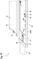
- Figure 15 shows a fourth embodiment of a sensor device 1 according to the invention in an exploded view.
- FIG Figure 15 shows a fourth embodiment of a sensor device 1 according to the invention in an exploded view.
- the sensor device 1 comprises an adhesive element 50 which, as in the first exemplary embodiment, forms the rear side 13 of the sensor device 1.
- a circuit board is integrally and integrally connected to the adhesive element 50.
- the circuit board is glued to the adhesive element 50.
- the circuit board comprises the memory board part 46 and the electronic board part 42.
- the memory board part 46 and the electronic board part 42 are thus formed in one piece and of the same material.
- a base plate 23 is formed in one piece and of the same material with the electronic board part 42 and the memory board part 46.
- the sensor board part 24 is arranged on the base plate 23.
- the sensor board part 24 is materially connected to the base plate 23, in particular soldered on.
- the sensor board part 24 contains the coils 21, at least one or two transmission coil (s) 21 being arranged between two receiving coils 21 within the sensor board part 24.
- the receiving and transmitting coils 21 are designed with the same or parallel coil axes 22.
- the coils 21 are electrically and cohesively connected to the base plate 23, in particular soldered on.
- the coils 21 are connected to the electrical system 40, d. h of the electronics 41 and the energy storage 45 connected.
- the base plate 23 spaced the coils 21 from the rear side 13 of the sensor device 1.
- the base plate is designed as part of the circuit board.
- a light barrier 52 is arranged within the sensor board part 24. By means of the light barrier 52, the position of the locking element 5 can be detected in addition to the sensor 20 designed as coils 21. It is also conceivable, however, to configure the fourth exemplary embodiment without a light barrier 52 and to detect the operating states only by means of the sensor 20.
- the holding element 31 is fastened on the adhesive element 50.
- the holding element 31 is designed as a plastic frame.
- the holding element 31 forms the electronics recess 33 as a through opening which serves as a trough for the potting compound 44.
- the electronics recess 33 also frames the sensor 20.
- the holding element 31 forms the energy storage receptacle 32 as a through opening.
- the energy stores 45 are arranged within the energy store receptacle 32.
- First electrical contacts for a first pole of the energy stores 45 are formed on the memory board part 46. Electrical line elements lead in or on the memory board part 46 to the electronics.
- Energy storage contacts 47 are applied to the second pole of energy storage 45.
- the energy storage contacts 47 are designed as elastic tongues of a cover 30.
- the cover 30 is electrically conductive, in particular metallic.
- the cover 30 comprises contact tongues 54, so that the electrical current can flow from the second pole of the energy store 45 via the energy storage contacts 47 to the contact tongues 54.
- the contact tongues 54 are resiliently and electrically contacting against a contact field 55 of the memory board part 46. Electrical conduction elements lead from the contact field in or on the memory board part 46 to the electronics.
- the adhesive element 50, the circuit board 42, 46 and the holding element 31 together form a rear housing part.
- the energy storage contacts 47 and the contact tongues 54 are designed to be resilient and rest under mechanical tension on the energy storage 45 or on the contact field 55 ensures the flow of current.
- the energy storage contacts 47 press the energy storage 45 against the electrical contacts for the first pole, so that the flow of current is also ensured here.
- the cover 30 is materially connected to a non-conductive film 51, in particular with adhesive tape.
- the film 51 forms part of the front side 12 of the sensor device 1.
- the film 51 and the cover 30 together form a front-side housing part.
- the front side 12 is formed by the potting compound 44 and the sensor board part 24.
- the transmitting and / or receiving unit 63 and the sensor 20 are materially connected to the front side 12 and the rear side 13.
- the sensor device 1 is embodied without a housing, that is to say the front and rear sides 12, 13 are materially connected to one another.
- the cover 30 is attached to the holding element 31 in a reversibly releasable manner, in particular in a form-fitting manner.
- the cover 30 comprises connecting elements 56, which can be guided through recesses 59 in the holding element 31. Thereafter, by moving the cover 30, the connecting elements 56 are brought into a form fit with projections 58 of the holding element 31 and thus fastened.
- the connecting elements 56 and the projections 58 are designed in such a way that the energy storage contacts 47 and the contact tongues 54 are mechanically tensioned when the cover is closed.
- the cover 30 can have projections which press the energy storage device 45 against the memory board part.
- a first method 100 according to the invention is shown.
- a first method step 101 it is stored in the computing unit 61 that the second stipulation is met when the user device 64 of a house resident is outside a predetermined, stored distance from a locking element 3 designed as a house door.
- the processing unit 61 it is also stored in the method step 100 that the first specification is met when the operating state "Open-bolt-extended-state", “Open-bolt-retracted-state", “Closed-bolt-retracted- State "or” sensor-outside the operating position state "should be present.
- a second method step 102 the acceleration sensor 53 detects that the house door 3 is being moved, whereupon the sensor device 2 repeatedly determines the operating state over a predetermined period of time stored in the sensor device 1. In this way, the operating states can be determined in an energy-saving manner when the front door is opened and then closed.
- the sensor device 2 sends the determined operating states to the computing unit 61.
- a third method step 103 the processing unit 61 receives location information as to where the user device 64 of the house occupant is located.
- a fourth method step 104 the computing unit 61 compares whether the user device 64 is located at the predetermined distance from the closure element 3. If the user device 64 is outside the distance from the closure element 3, the computing unit 61 determines that the second specification has been met.
- a fifth method step 105 the computing unit 61 compares the most recently transmitted operating state with the first specification. If the most recently transmitted operating state corresponds to one of the operating states stored as the first specification, the computing unit 61 determines that the two specifications are met.
- the processing unit 61 sends the message “front door is not locked” to the user device 64. The user device 64 then shows the message on the display of the user device 64.
- the computing unit 61 sends the message “front door is not locked” to the user device 64 from a predetermined distance from the house.
- step 101 it is stored in the arithmetic unit 61 that the second stipulation is met when a user device 64 named in the arithmetic unit of each house occupant is located outside a predetermined, stored distance from the closure element 3.
- the processing unit 61 receives location information as to where the stored user devices 64 of the house residents are located.
- the computing unit 61 compares whether each of the stored user devices 64 is located at least at the predetermined distance from the closure element 3. If all of the stored user devices 64 are outside the distance from the closure element 3, the computing unit 61 determines that the second specification has been met.
- the fifth method step 105 takes place as already described.
- the processing unit 61 sends the message to each stored user device 64.
- FIG. 17 is a method 200 according to the invention, which can be used as a modification of the method 100 in FIG Figure 16 is formed, shown.
- Method steps 201 to 205 correspond to the described method steps 101 to 105 if several user devices 64 are stored. Deviating from the in Figure 16
- the message is not output to all user devices 64, but only to the user device that fulfills a further specification, e.g. B. that of the front door 3 is closest.
- a further method step 207 it is checked for a predetermined time whether the operating state of the house door changes to the operating state “closed-bolt-extended-state”. If this is the case, the method 200 is ended. If this is not the case, a message is output to the other stored user devices 64 in a next method step 208. The message is "Front door is not locked and user XY is not responding”. The message is displayed on the remaining user devices 64.
- a further exemplary method 300 is shown.
- a first method step 301 it is stored in the arithmetic unit 61 that the second specification is met if a reservation of the room that closes the closure element 3 is stored in a digital calendar at the current time.
- the room can be a conference room in an office building.
- the first requirement is that the "open" operating state was not assumed in a time interval at the beginning of the room reservation.
- the processing unit receives the additional information that a room reservation of the room, beginning at the beginning of the reservation, has been made.
- the processing unit 61 causes the sensor device 2 to repeatedly determine the operating state and transmit it to the processing unit 61 in the time interval that begins before the start of the reservation and ends after the start of the reservation.
- the computing unit checks at the end of the time interval whether the operating state is “open”, in particular the "Open-bolt-retracted” or "Open-bolt-extended” operating status, in which there was a time interval. If this is not the case, the first requirement has been met.
- the computing unit 61 causes the digital calendar to no longer display the room as reserved. This corresponds to the output of the message.
Applications Claiming Priority (1)
| Application Number | Priority Date | Filing Date | Title |
|---|---|---|---|
| EP19212277 | 2019-11-28 |
Publications (1)
| Publication Number | Publication Date |
|---|---|
| EP3828860A1 true EP3828860A1 (fr) | 2021-06-02 |
Family
ID=68732748
Family Applications (1)
| Application Number | Title | Priority Date | Filing Date |
|---|---|---|---|
| EP20210182.0A Pending EP3828860A1 (fr) | 2019-11-28 | 2020-11-27 | Procédé d'émission d'un message d'un système de capteur |
Country Status (1)
| Country | Link |
|---|---|
| EP (1) | EP3828860A1 (fr) |
Citations (5)
| Publication number | Priority date | Publication date | Assignee | Title |
|---|---|---|---|---|
| US20120280783A1 (en) * | 2011-05-02 | 2012-11-08 | Apigy Inc. | Systems and methods for controlling a locking mechanism using a portable electronic device |
| WO2016149723A1 (fr) | 2015-03-23 | 2016-09-29 | Kaba Gmbh | Serrure ou ferrure de fenêtre ou de porte |
| US20170175419A1 (en) * | 2015-12-18 | 2017-06-22 | Inventec (Pudong) Technology Corporation | Smart Door Lock System And Method Thereof |
| US20180091327A1 (en) * | 2016-09-24 | 2018-03-29 | Apple Inc. | Anomaly Detection By Resident Device |
| US20180340350A1 (en) * | 2013-03-15 | 2018-11-29 | August Home, Inc. | Intelligent door lock system with manual operation and push notification |
-
2020
- 2020-11-27 EP EP20210182.0A patent/EP3828860A1/fr active Pending
Patent Citations (5)
| Publication number | Priority date | Publication date | Assignee | Title |
|---|---|---|---|---|
| US20120280783A1 (en) * | 2011-05-02 | 2012-11-08 | Apigy Inc. | Systems and methods for controlling a locking mechanism using a portable electronic device |
| US20180340350A1 (en) * | 2013-03-15 | 2018-11-29 | August Home, Inc. | Intelligent door lock system with manual operation and push notification |
| WO2016149723A1 (fr) | 2015-03-23 | 2016-09-29 | Kaba Gmbh | Serrure ou ferrure de fenêtre ou de porte |
| US20170175419A1 (en) * | 2015-12-18 | 2017-06-22 | Inventec (Pudong) Technology Corporation | Smart Door Lock System And Method Thereof |
| US20180091327A1 (en) * | 2016-09-24 | 2018-03-29 | Apple Inc. | Anomaly Detection By Resident Device |
Similar Documents
| Publication | Publication Date | Title |
|---|---|---|
| EP3077998B1 (fr) | Procédé de désactivation du verrouillage d'au moins une porte d'un boîtier | |
| AT395632B (de) | Schliessfachanlage mit mehreren schliessfaechern | |
| DE112016004841T5 (de) | Elektronisches Schloss und elektronisches Verriegelungssystem für Möbel, Schränke oder Schliessfächer | |
| DE2838056C2 (de) | Schließanlage für Gebrauchsschlösser mit einem Schlüsselsignalsender und einem Schlüsselsignalempfänger | |
| EP1718997A1 (fr) | Radar de proximite comportant des detecteurs multiples servant a localiser des objets inclus dans un milieu | |
| EP1631792A1 (fr) | Capteur servant a detecter la position d'un dispositif de transmission de force mecanique | |
| DE102011008654A1 (de) | Beschlagsintegrierte Überwachungseinrichtung | |
| DE10206968A1 (de) | Verfahren zur Erkennung einer Bedienung einer Handhabe mit einem kapazitiven Sensor | |
| DE19744989C2 (de) | Überwachungseinrichtung | |
| DE102016002606A1 (de) | Vorrichtung zur Erfassung der Position eines Fenster- oder Türgriffs | |
| DE19815768C2 (de) | Kippfensterverriegelung einer Objektsicherungsanlage | |
| EP3828860A1 (fr) | Procédé d'émission d'un message d'un système de capteur | |
| EP0949597B1 (fr) | Verrou mécanique pour fenêtre ou porte d'une installation pour la securité d'objets fonctionnant sans fil | |
| EP1390595B1 (fr) | Dispositif pour le deverrouillage d'une porte a l'aide d'une telecommande sans fil | |
| EP3832613A1 (fr) | Système de capteur pour élément de verrouillage, en particulier une porte ou une fenêtre | |
| EP3828857A1 (fr) | Système de capteur | |
| DE202015008986U1 (de) | Fenster- oder Türgriff mit einer Vorrichtung zur Erfassung der Griffposition | |
| EP3828843A1 (fr) | Système de capteur | |
| EP3828856A1 (fr) | Système de capteur | |
| EP3748590A1 (fr) | Appareil d'authentification pouvant être monté au mur | |
| DE102019132382A1 (de) | Sensorvorrichtung | |
| EP3828844A1 (fr) | Dispositif capteur | |
| EP3828366A1 (fr) | Dispositif capteur | |
| EP2955701A2 (fr) | Système de fermeture électromécanique radio-commandé et procédé de fonction d'un système de fermeture électromécanique radio-commandé | |
| DE102015113243B4 (de) | Drahtlos mit einer Zentraleinheit kommunizierendes Schranktürschloss |
Legal Events
| Date | Code | Title | Description |
|---|---|---|---|
| PUAI | Public reference made under article 153(3) epc to a published international application that has entered the european phase |
Free format text: ORIGINAL CODE: 0009012 |
|
| STAA | Information on the status of an ep patent application or granted ep patent |
Free format text: STATUS: THE APPLICATION HAS BEEN PUBLISHED |
|
| AK | Designated contracting states |
Kind code of ref document: A1 Designated state(s): AL AT BE BG CH CY CZ DE DK EE ES FI FR GB GR HR HU IE IS IT LI LT LU LV MC MK MT NL NO PL PT RO RS SE SI SK SM TR |
|
| STAA | Information on the status of an ep patent application or granted ep patent |
Free format text: STATUS: REQUEST FOR EXAMINATION WAS MADE |
|
| 17P | Request for examination filed |
Effective date: 20211202 |
|
| RBV | Designated contracting states (corrected) |
Designated state(s): AL AT BE BG CH CY CZ DE DK EE ES FI FR GB GR HR HU IE IS IT LI LT LU LV MC MK MT NL NO PL PT RO RS SE SI SK SM TR |
|
| REG | Reference to a national code |
Ref country code: DE Ref legal event code: R079 Free format text: PREVIOUS MAIN CLASS: G08B0025080000 Ipc: G08B0013080000 |
|
| GRAP | Despatch of communication of intention to grant a patent |
Free format text: ORIGINAL CODE: EPIDOSNIGR1 |
|
| STAA | Information on the status of an ep patent application or granted ep patent |
Free format text: STATUS: GRANT OF PATENT IS INTENDED |
|
| RIC1 | Information provided on ipc code assigned before grant |
Ipc: H04W 52/02 20090101ALN20240229BHEP Ipc: G08B 25/00 20060101ALN20240229BHEP Ipc: G07C 9/00 20200101ALI20240229BHEP Ipc: G08B 13/08 20060101AFI20240229BHEP |
|
| RIC1 | Information provided on ipc code assigned before grant |
Ipc: H04W 52/02 20090101ALN20240301BHEP Ipc: G08B 25/00 20060101ALN20240301BHEP Ipc: G07C 9/00 20200101ALI20240301BHEP Ipc: G08B 13/08 20060101AFI20240301BHEP |
|
| RIC1 | Information provided on ipc code assigned before grant |
Ipc: H04W 52/02 20090101ALN20240308BHEP Ipc: G08B 25/00 20060101ALN20240308BHEP Ipc: G07C 9/00 20200101ALI20240308BHEP Ipc: G08B 13/08 20060101AFI20240308BHEP |
|
| INTG | Intention to grant announced |
Effective date: 20240325 |