EP3828587A1 - Verfahren zur bestimmung der position eines fahrzeugs - Google Patents
Verfahren zur bestimmung der position eines fahrzeugs Download PDFInfo
- Publication number
- EP3828587A1 EP3828587A1 EP19212492.3A EP19212492A EP3828587A1 EP 3828587 A1 EP3828587 A1 EP 3828587A1 EP 19212492 A EP19212492 A EP 19212492A EP 3828587 A1 EP3828587 A1 EP 3828587A1
- Authority
- EP
- European Patent Office
- Prior art keywords
- map
- elements
- environment
- vehicle
- matching
- Prior art date
- Legal status (The legal status is an assumption and is not a legal conclusion. Google has not performed a legal analysis and makes no representation as to the accuracy of the status listed.)
- Pending
Links
- 238000000034 method Methods 0.000 title claims abstract description 51
- 238000001514 detection method Methods 0.000 claims abstract description 98
- 230000003068 static effect Effects 0.000 claims abstract description 7
- 239000002245 particle Substances 0.000 claims description 10
- 230000005670 electromagnetic radiation Effects 0.000 claims description 9
- 230000009466 transformation Effects 0.000 claims description 8
- 238000001914 filtration Methods 0.000 claims description 5
- 238000000342 Monte Carlo simulation Methods 0.000 claims description 3
- 230000005855 radiation Effects 0.000 claims description 2
- 238000005259 measurement Methods 0.000 description 9
- 238000004422 calculation algorithm Methods 0.000 description 8
- 230000006870 function Effects 0.000 description 7
- 238000010586 diagram Methods 0.000 description 5
- 238000004364 calculation method Methods 0.000 description 4
- 238000013500 data storage Methods 0.000 description 4
- 230000014509 gene expression Effects 0.000 description 4
- 230000008569 process Effects 0.000 description 3
- 230000000644 propagated effect Effects 0.000 description 3
- 238000013459 approach Methods 0.000 description 2
- 238000004590 computer program Methods 0.000 description 2
- 230000004807 localization Effects 0.000 description 2
- 230000009467 reduction Effects 0.000 description 2
- 230000001131 transforming effect Effects 0.000 description 2
- 230000004888 barrier function Effects 0.000 description 1
- 230000008901 benefit Effects 0.000 description 1
- 230000001419 dependent effect Effects 0.000 description 1
- 238000011161 development Methods 0.000 description 1
- 230000018109 developmental process Effects 0.000 description 1
- 230000000694 effects Effects 0.000 description 1
- 238000002474 experimental method Methods 0.000 description 1
- 230000003287 optical effect Effects 0.000 description 1
- 238000005192 partition Methods 0.000 description 1
- 230000002085 persistent effect Effects 0.000 description 1
- 238000012545 processing Methods 0.000 description 1
- 239000007787 solid Substances 0.000 description 1
- 238000012360 testing method Methods 0.000 description 1
- 238000013519 translation Methods 0.000 description 1
Images


Classifications
-
- G—PHYSICS
- G01—MEASURING; TESTING
- G01C—MEASURING DISTANCES, LEVELS OR BEARINGS; SURVEYING; NAVIGATION; GYROSCOPIC INSTRUMENTS; PHOTOGRAMMETRY OR VIDEOGRAMMETRY
- G01C21/00—Navigation; Navigational instruments not provided for in groups G01C1/00 - G01C19/00
- G01C21/26—Navigation; Navigational instruments not provided for in groups G01C1/00 - G01C19/00 specially adapted for navigation in a road network
- G01C21/28—Navigation; Navigational instruments not provided for in groups G01C1/00 - G01C19/00 specially adapted for navigation in a road network with correlation of data from several navigational instruments
- G01C21/30—Map- or contour-matching
- G01C21/32—Structuring or formatting of map data
-
- G—PHYSICS
- G01—MEASURING; TESTING
- G01C—MEASURING DISTANCES, LEVELS OR BEARINGS; SURVEYING; NAVIGATION; GYROSCOPIC INSTRUMENTS; PHOTOGRAMMETRY OR VIDEOGRAMMETRY
- G01C21/00—Navigation; Navigational instruments not provided for in groups G01C1/00 - G01C19/00
- G01C21/38—Electronic maps specially adapted for navigation; Updating thereof
- G01C21/3804—Creation or updating of map data
- G01C21/3807—Creation or updating of map data characterised by the type of data
- G01C21/3811—Point data, e.g. Point of Interest [POI]
-
- G—PHYSICS
- G01—MEASURING; TESTING
- G01S—RADIO DIRECTION-FINDING; RADIO NAVIGATION; DETERMINING DISTANCE OR VELOCITY BY USE OF RADIO WAVES; LOCATING OR PRESENCE-DETECTING BY USE OF THE REFLECTION OR RERADIATION OF RADIO WAVES; ANALOGOUS ARRANGEMENTS USING OTHER WAVES
- G01S7/00—Details of systems according to groups G01S13/00, G01S15/00, G01S17/00
- G01S7/02—Details of systems according to groups G01S13/00, G01S15/00, G01S17/00 of systems according to group G01S13/00
- G01S7/28—Details of pulse systems
- G01S7/285—Receivers
- G01S7/295—Means for transforming co-ordinates or for evaluating data, e.g. using computers
- G01S7/2955—Means for determining the position of the radar coordinate system for evaluating the position data of the target in another coordinate system
-
- G—PHYSICS
- G01—MEASURING; TESTING
- G01C—MEASURING DISTANCES, LEVELS OR BEARINGS; SURVEYING; NAVIGATION; GYROSCOPIC INSTRUMENTS; PHOTOGRAMMETRY OR VIDEOGRAMMETRY
- G01C21/00—Navigation; Navigational instruments not provided for in groups G01C1/00 - G01C19/00
- G01C21/26—Navigation; Navigational instruments not provided for in groups G01C1/00 - G01C19/00 specially adapted for navigation in a road network
- G01C21/28—Navigation; Navigational instruments not provided for in groups G01C1/00 - G01C19/00 specially adapted for navigation in a road network with correlation of data from several navigational instruments
- G01C21/30—Map- or contour-matching
-
- G—PHYSICS
- G01—MEASURING; TESTING
- G01C—MEASURING DISTANCES, LEVELS OR BEARINGS; SURVEYING; NAVIGATION; GYROSCOPIC INSTRUMENTS; PHOTOGRAMMETRY OR VIDEOGRAMMETRY
- G01C21/00—Navigation; Navigational instruments not provided for in groups G01C1/00 - G01C19/00
- G01C21/26—Navigation; Navigational instruments not provided for in groups G01C1/00 - G01C19/00 specially adapted for navigation in a road network
- G01C21/34—Route searching; Route guidance
- G01C21/36—Input/output arrangements for on-board computers
- G01C21/3602—Input other than that of destination using image analysis, e.g. detection of road signs, lanes, buildings, real preceding vehicles using a camera
-
- G—PHYSICS
- G01—MEASURING; TESTING
- G01C—MEASURING DISTANCES, LEVELS OR BEARINGS; SURVEYING; NAVIGATION; GYROSCOPIC INSTRUMENTS; PHOTOGRAMMETRY OR VIDEOGRAMMETRY
- G01C21/00—Navigation; Navigational instruments not provided for in groups G01C1/00 - G01C19/00
- G01C21/38—Electronic maps specially adapted for navigation; Updating thereof
- G01C21/3804—Creation or updating of map data
- G01C21/3833—Creation or updating of map data characterised by the source of data
- G01C21/3848—Data obtained from both position sensors and additional sensors
-
- G—PHYSICS
- G01—MEASURING; TESTING
- G01C—MEASURING DISTANCES, LEVELS OR BEARINGS; SURVEYING; NAVIGATION; GYROSCOPIC INSTRUMENTS; PHOTOGRAMMETRY OR VIDEOGRAMMETRY
- G01C21/00—Navigation; Navigational instruments not provided for in groups G01C1/00 - G01C19/00
- G01C21/38—Electronic maps specially adapted for navigation; Updating thereof
- G01C21/3863—Structures of map data
- G01C21/387—Organisation of map data, e.g. version management or database structures
-
- G—PHYSICS
- G01—MEASURING; TESTING
- G01S—RADIO DIRECTION-FINDING; RADIO NAVIGATION; DETERMINING DISTANCE OR VELOCITY BY USE OF RADIO WAVES; LOCATING OR PRESENCE-DETECTING BY USE OF THE REFLECTION OR RERADIATION OF RADIO WAVES; ANALOGOUS ARRANGEMENTS USING OTHER WAVES
- G01S13/00—Systems using the reflection or reradiation of radio waves, e.g. radar systems; Analogous systems using reflection or reradiation of waves whose nature or wavelength is irrelevant or unspecified
- G01S13/66—Radar-tracking systems; Analogous systems
- G01S13/72—Radar-tracking systems; Analogous systems for two-dimensional tracking, e.g. combination of angle and range tracking, track-while-scan radar
- G01S13/723—Radar-tracking systems; Analogous systems for two-dimensional tracking, e.g. combination of angle and range tracking, track-while-scan radar by using numerical data
-
- G—PHYSICS
- G01—MEASURING; TESTING
- G01S—RADIO DIRECTION-FINDING; RADIO NAVIGATION; DETERMINING DISTANCE OR VELOCITY BY USE OF RADIO WAVES; LOCATING OR PRESENCE-DETECTING BY USE OF THE REFLECTION OR RERADIATION OF RADIO WAVES; ANALOGOUS ARRANGEMENTS USING OTHER WAVES
- G01S13/00—Systems using the reflection or reradiation of radio waves, e.g. radar systems; Analogous systems using reflection or reradiation of waves whose nature or wavelength is irrelevant or unspecified
- G01S13/87—Combinations of radar systems, e.g. primary radar and secondary radar
- G01S13/876—Combination of several spaced transponders or reflectors of known location for determining the position of a receiver
-
- G—PHYSICS
- G01—MEASURING; TESTING
- G01S—RADIO DIRECTION-FINDING; RADIO NAVIGATION; DETERMINING DISTANCE OR VELOCITY BY USE OF RADIO WAVES; LOCATING OR PRESENCE-DETECTING BY USE OF THE REFLECTION OR RERADIATION OF RADIO WAVES; ANALOGOUS ARRANGEMENTS USING OTHER WAVES
- G01S13/00—Systems using the reflection or reradiation of radio waves, e.g. radar systems; Analogous systems using reflection or reradiation of waves whose nature or wavelength is irrelevant or unspecified
- G01S13/88—Radar or analogous systems specially adapted for specific applications
- G01S13/89—Radar or analogous systems specially adapted for specific applications for mapping or imaging
-
- G—PHYSICS
- G01—MEASURING; TESTING
- G01S—RADIO DIRECTION-FINDING; RADIO NAVIGATION; DETERMINING DISTANCE OR VELOCITY BY USE OF RADIO WAVES; LOCATING OR PRESENCE-DETECTING BY USE OF THE REFLECTION OR RERADIATION OF RADIO WAVES; ANALOGOUS ARRANGEMENTS USING OTHER WAVES
- G01S17/00—Systems using the reflection or reradiation of electromagnetic waves other than radio waves, e.g. lidar systems
- G01S17/66—Tracking systems using electromagnetic waves other than radio waves
-
- G—PHYSICS
- G01—MEASURING; TESTING
- G01S—RADIO DIRECTION-FINDING; RADIO NAVIGATION; DETERMINING DISTANCE OR VELOCITY BY USE OF RADIO WAVES; LOCATING OR PRESENCE-DETECTING BY USE OF THE REFLECTION OR RERADIATION OF RADIO WAVES; ANALOGOUS ARRANGEMENTS USING OTHER WAVES
- G01S17/00—Systems using the reflection or reradiation of electromagnetic waves other than radio waves, e.g. lidar systems
- G01S17/86—Combinations of lidar systems with systems other than lidar, radar or sonar, e.g. with direction finders
-
- G—PHYSICS
- G01—MEASURING; TESTING
- G01S—RADIO DIRECTION-FINDING; RADIO NAVIGATION; DETERMINING DISTANCE OR VELOCITY BY USE OF RADIO WAVES; LOCATING OR PRESENCE-DETECTING BY USE OF THE REFLECTION OR RERADIATION OF RADIO WAVES; ANALOGOUS ARRANGEMENTS USING OTHER WAVES
- G01S17/00—Systems using the reflection or reradiation of electromagnetic waves other than radio waves, e.g. lidar systems
- G01S17/88—Lidar systems specially adapted for specific applications
- G01S17/89—Lidar systems specially adapted for specific applications for mapping or imaging
-
- G—PHYSICS
- G01—MEASURING; TESTING
- G01S—RADIO DIRECTION-FINDING; RADIO NAVIGATION; DETERMINING DISTANCE OR VELOCITY BY USE OF RADIO WAVES; LOCATING OR PRESENCE-DETECTING BY USE OF THE REFLECTION OR RERADIATION OF RADIO WAVES; ANALOGOUS ARRANGEMENTS USING OTHER WAVES
- G01S7/00—Details of systems according to groups G01S13/00, G01S15/00, G01S17/00
- G01S7/02—Details of systems according to groups G01S13/00, G01S15/00, G01S17/00 of systems according to group G01S13/00
- G01S7/41—Details of systems according to groups G01S13/00, G01S15/00, G01S17/00 of systems according to group G01S13/00 using analysis of echo signal for target characterisation; Target signature; Target cross-section
- G01S7/415—Identification of targets based on measurements of movement associated with the target
-
- G—PHYSICS
- G01—MEASURING; TESTING
- G01S—RADIO DIRECTION-FINDING; RADIO NAVIGATION; DETERMINING DISTANCE OR VELOCITY BY USE OF RADIO WAVES; LOCATING OR PRESENCE-DETECTING BY USE OF THE REFLECTION OR RERADIATION OF RADIO WAVES; ANALOGOUS ARRANGEMENTS USING OTHER WAVES
- G01S7/00—Details of systems according to groups G01S13/00, G01S15/00, G01S17/00
- G01S7/52—Details of systems according to groups G01S13/00, G01S15/00, G01S17/00 of systems according to group G01S15/00
- G01S7/539—Details of systems according to groups G01S13/00, G01S15/00, G01S17/00 of systems according to group G01S15/00 using analysis of echo signal for target characterisation; Target signature; Target cross-section
-
- G—PHYSICS
- G01—MEASURING; TESTING
- G01S—RADIO DIRECTION-FINDING; RADIO NAVIGATION; DETERMINING DISTANCE OR VELOCITY BY USE OF RADIO WAVES; LOCATING OR PRESENCE-DETECTING BY USE OF THE REFLECTION OR RERADIATION OF RADIO WAVES; ANALOGOUS ARRANGEMENTS USING OTHER WAVES
- G01S13/00—Systems using the reflection or reradiation of radio waves, e.g. radar systems; Analogous systems using reflection or reradiation of waves whose nature or wavelength is irrelevant or unspecified
- G01S13/02—Systems using reflection of radio waves, e.g. primary radar systems; Analogous systems
- G01S13/50—Systems of measurement based on relative movement of target
- G01S13/58—Velocity or trajectory determination systems; Sense-of-movement determination systems
- G01S13/589—Velocity or trajectory determination systems; Sense-of-movement determination systems measuring the velocity vector
-
- G—PHYSICS
- G01—MEASURING; TESTING
- G01S—RADIO DIRECTION-FINDING; RADIO NAVIGATION; DETERMINING DISTANCE OR VELOCITY BY USE OF RADIO WAVES; LOCATING OR PRESENCE-DETECTING BY USE OF THE REFLECTION OR RERADIATION OF RADIO WAVES; ANALOGOUS ARRANGEMENTS USING OTHER WAVES
- G01S13/00—Systems using the reflection or reradiation of radio waves, e.g. radar systems; Analogous systems using reflection or reradiation of waves whose nature or wavelength is irrelevant or unspecified
- G01S13/86—Combinations of radar systems with non-radar systems, e.g. sonar, direction finder
- G01S13/865—Combination of radar systems with lidar systems
-
- G—PHYSICS
- G01—MEASURING; TESTING
- G01S—RADIO DIRECTION-FINDING; RADIO NAVIGATION; DETERMINING DISTANCE OR VELOCITY BY USE OF RADIO WAVES; LOCATING OR PRESENCE-DETECTING BY USE OF THE REFLECTION OR RERADIATION OF RADIO WAVES; ANALOGOUS ARRANGEMENTS USING OTHER WAVES
- G01S13/00—Systems using the reflection or reradiation of radio waves, e.g. radar systems; Analogous systems using reflection or reradiation of waves whose nature or wavelength is irrelevant or unspecified
- G01S13/86—Combinations of radar systems with non-radar systems, e.g. sonar, direction finder
- G01S13/867—Combination of radar systems with cameras
-
- G—PHYSICS
- G01—MEASURING; TESTING
- G01S—RADIO DIRECTION-FINDING; RADIO NAVIGATION; DETERMINING DISTANCE OR VELOCITY BY USE OF RADIO WAVES; LOCATING OR PRESENCE-DETECTING BY USE OF THE REFLECTION OR RERADIATION OF RADIO WAVES; ANALOGOUS ARRANGEMENTS USING OTHER WAVES
- G01S17/00—Systems using the reflection or reradiation of electromagnetic waves other than radio waves, e.g. lidar systems
- G01S17/88—Lidar systems specially adapted for specific applications
- G01S17/93—Lidar systems specially adapted for specific applications for anti-collision purposes
- G01S17/931—Lidar systems specially adapted for specific applications for anti-collision purposes of land vehicles
-
- G—PHYSICS
- G01—MEASURING; TESTING
- G01S—RADIO DIRECTION-FINDING; RADIO NAVIGATION; DETERMINING DISTANCE OR VELOCITY BY USE OF RADIO WAVES; LOCATING OR PRESENCE-DETECTING BY USE OF THE REFLECTION OR RERADIATION OF RADIO WAVES; ANALOGOUS ARRANGEMENTS USING OTHER WAVES
- G01S13/00—Systems using the reflection or reradiation of radio waves, e.g. radar systems; Analogous systems using reflection or reradiation of waves whose nature or wavelength is irrelevant or unspecified
- G01S13/88—Radar or analogous systems specially adapted for specific applications
- G01S13/93—Radar or analogous systems specially adapted for specific applications for anti-collision purposes
- G01S13/931—Radar or analogous systems specially adapted for specific applications for anti-collision purposes of land vehicles
- G01S2013/932—Radar or analogous systems specially adapted for specific applications for anti-collision purposes of land vehicles using own vehicle data, e.g. ground speed, steering wheel direction
-
- G—PHYSICS
- G01—MEASURING; TESTING
- G01S—RADIO DIRECTION-FINDING; RADIO NAVIGATION; DETERMINING DISTANCE OR VELOCITY BY USE OF RADIO WAVES; LOCATING OR PRESENCE-DETECTING BY USE OF THE REFLECTION OR RERADIATION OF RADIO WAVES; ANALOGOUS ARRANGEMENTS USING OTHER WAVES
- G01S13/00—Systems using the reflection or reradiation of radio waves, e.g. radar systems; Analogous systems using reflection or reradiation of waves whose nature or wavelength is irrelevant or unspecified
- G01S13/88—Radar or analogous systems specially adapted for specific applications
- G01S13/93—Radar or analogous systems specially adapted for specific applications for anti-collision purposes
- G01S13/931—Radar or analogous systems specially adapted for specific applications for anti-collision purposes of land vehicles
- G01S2013/9323—Alternative operation using light waves
-
- G—PHYSICS
- G01—MEASURING; TESTING
- G01S—RADIO DIRECTION-FINDING; RADIO NAVIGATION; DETERMINING DISTANCE OR VELOCITY BY USE OF RADIO WAVES; LOCATING OR PRESENCE-DETECTING BY USE OF THE REFLECTION OR RERADIATION OF RADIO WAVES; ANALOGOUS ARRANGEMENTS USING OTHER WAVES
- G01S13/00—Systems using the reflection or reradiation of radio waves, e.g. radar systems; Analogous systems using reflection or reradiation of waves whose nature or wavelength is irrelevant or unspecified
- G01S13/88—Radar or analogous systems specially adapted for specific applications
- G01S13/93—Radar or analogous systems specially adapted for specific applications for anti-collision purposes
- G01S13/931—Radar or analogous systems specially adapted for specific applications for anti-collision purposes of land vehicles
- G01S2013/9327—Sensor installation details
- G01S2013/93271—Sensor installation details in the front of the vehicles
-
- G—PHYSICS
- G01—MEASURING; TESTING
- G01S—RADIO DIRECTION-FINDING; RADIO NAVIGATION; DETERMINING DISTANCE OR VELOCITY BY USE OF RADIO WAVES; LOCATING OR PRESENCE-DETECTING BY USE OF THE REFLECTION OR RERADIATION OF RADIO WAVES; ANALOGOUS ARRANGEMENTS USING OTHER WAVES
- G01S13/00—Systems using the reflection or reradiation of radio waves, e.g. radar systems; Analogous systems using reflection or reradiation of waves whose nature or wavelength is irrelevant or unspecified
- G01S13/88—Radar or analogous systems specially adapted for specific applications
- G01S13/93—Radar or analogous systems specially adapted for specific applications for anti-collision purposes
- G01S13/931—Radar or analogous systems specially adapted for specific applications for anti-collision purposes of land vehicles
- G01S2013/9327—Sensor installation details
- G01S2013/93274—Sensor installation details on the side of the vehicles
-
- G—PHYSICS
- G01—MEASURING; TESTING
- G01S—RADIO DIRECTION-FINDING; RADIO NAVIGATION; DETERMINING DISTANCE OR VELOCITY BY USE OF RADIO WAVES; LOCATING OR PRESENCE-DETECTING BY USE OF THE REFLECTION OR RERADIATION OF RADIO WAVES; ANALOGOUS ARRANGEMENTS USING OTHER WAVES
- G01S7/00—Details of systems according to groups G01S13/00, G01S15/00, G01S17/00
- G01S7/003—Transmission of data between radar, sonar or lidar systems and remote stations
-
- G—PHYSICS
- G01—MEASURING; TESTING
- G01S—RADIO DIRECTION-FINDING; RADIO NAVIGATION; DETERMINING DISTANCE OR VELOCITY BY USE OF RADIO WAVES; LOCATING OR PRESENCE-DETECTING BY USE OF THE REFLECTION OR RERADIATION OF RADIO WAVES; ANALOGOUS ARRANGEMENTS USING OTHER WAVES
- G01S7/00—Details of systems according to groups G01S13/00, G01S15/00, G01S17/00
- G01S7/02—Details of systems according to groups G01S13/00, G01S15/00, G01S17/00 of systems according to group G01S13/00
- G01S7/41—Details of systems according to groups G01S13/00, G01S15/00, G01S17/00 of systems according to group G01S13/00 using analysis of echo signal for target characterisation; Target signature; Target cross-section
- G01S7/417—Details of systems according to groups G01S13/00, G01S15/00, G01S17/00 of systems according to group G01S13/00 using analysis of echo signal for target characterisation; Target signature; Target cross-section involving the use of neural networks
Definitions
- the present disclosure relates to a computer implemented method for determining the position of a vehicle.
- a method for determining the position of a vehicle can be provided for a vehicle which is equipped with a sensor system, wherein the sensor system includes at least one sensor for receiving electromagnetic radiation emitted from at least one emitter of the sensor system and reflected in a vehicle environment towards the at least one sensor.
- the method comprises: determining at least one scan comprising a plurality of detection points, wherein each detection point is evaluated from electromagnetic radiation received by the at least one sensor and representing a location in the vehicle environment; determining, from a database, a predefined map, wherein the map comprises a plurality of elements in a map environment, each of the elements representing a respective one of a plurality of static landmarks in the vehicle environment, and the map environment representing the vehicle environment; matching the plurality of detection points and the plurality of elements of the predefined map; determining the position of the vehicle based on the matching.
- Self-localization or ego-localization of a vehicle with respect to a predefined map such as a navigation map is an important task in the field of autonomous driving and similar applications.
- On-board radar systems are able to detect objects like buildings, trees, poles and other vehicles - even under bad weather conditions.
- the radar detections acquired by a radar system can be used to localize the vehicle within the navigation map.
- the navigation map can be gathered from a publicly available database. For example, it can be a so called "OpenStreetMap". Alternatively, the navigation map can be provided by a commercial map provider. Such maps usually are particularly accurate. Generally, the navigation map can be derived from a global database on the basis of a given position of the vehicle, e.g. from a global position system of the vehicle. Alternatively, a preliminary position estimate can be determined using odometry.
- the static landmarks can be known static objects, i.e. infrastructural objects or persistent objects, like walls of buildings, barriers, fences, pavement edges, poles, bigger plants, trees and the like.
- the map data stored in the database comprise simplified mathematical representations of the landmarks, for example in the form of extended geometrical objects like lines.
- Each of the elements comprises information about its position in a world coordinate system.
- the term "matching" can be understood in the sense of evaluating a correspondence between the radar detection points and the elements of the map.
- a so called Scan Matching algorithm can be applied.
- An example of a Scan Matching algorithm is disclosed in the European patent application number 18153439.7 .
- Scan Matching the correspondence between the detection points and the elements of the map is exploited for the determination of the position of the vehicle.
- the methods can use a radar system of a vehicle, it is understood that the methods may also be adopted using detection points of a LiDAR system instead of a radar system. Combinations of radar and LiDAR detection points may also be possible.
- Every scan of a current set of (e.g. radar) scans can be projected into the closest map element (Building/wall).
- the closest map element has to be identified before the projection. If the scan matching algorithm is executed in a more complex environment within a large area, e.g. a whole city, consisting of more buildings/walls or applied for every radar scan recursively/circularly the computational effort increases and a more sophisticated approach for calculating the map projection is needed.
- the present disclosure provides a computer implemented method, a computer system and a non-transitory computer readable medium according to the independent claims. Embodiments are given in the subclaims, the description and the drawings.
- the present disclosure is directed at a computer implemented method for determining the position of a vehicle equipped with a sensor system, wherein the sensor system includes at least one sensor for receiving electromagnetic radiation emitted from at least one emitter of the sensor system and reflected in a vehicle environment towards the at least one sensor, wherein the method comprises: capturing at least one scan comprising a plurality of detection points, wherein each detection point is evaluated from electromagnetic radiation received by the at least one sensor and representing a location in the vehicle environment; determining, from a database, a predefined map, wherein the map comprises a plurality of elements in a map environment, each of the elements representing a respective one of a plurality of static landmarks in the vehicle environment, and the map environment representing the vehicle environment; matching the plurality of detection points and the plurality of elements of the map; determining the position of the vehicle based on the matching; wherein the predefined map further comprises a spatial assignment of a plurality of parts of the map environment to the plurality of elements, and wherein the spatial assignment is used for the
- the spatial assignment allows for a more efficient assignment between the detection points and the elements. This means that for assigning a given detection point to one or more of the elements it is not necessary to carry out an exhaustive search through the elements, for example in order to find the nearest element for the given detection point. Instead, the spatial assignment readily gives the information to which element a given detection point is assigned.
- the spatial assignment can be regarded as an additional layer of the map, which is pre-computed, i.e. predetermined so that complex assignment steps can be avoided during runtime of the method.
- the method therefore enables a particularly efficient self-localization of vehicles within any kind of environment and in particular in urban environments. In experiments, it has been found that the proposed method outperforms conventional scan matching algorithms by 35 percent in time.
- the emitter of the sensor system can emit electromagnetic radiation during determining the one or more scans.
- the sensor system can be a radar sensor system and the detection points can be radar detection points.
- the predefined map comprises a definition of a plurality of spatial segments, each of the spatial segments representing a part of the map environment and being assigned to a respective one of the plurality of elements.
- the spatial segments can be configured as so-called Voronoi segments or cells.
- the Voronoi segments form a Voronoi diagram, which can be used as an additional layer of the map.
- a Voronoi diagram is a partition into regions of detection points, which have the closest distance to a respective element from all elements of the map (e.g., points or lines). It can give a probability for assignment of a detection point to its nearest map element.
- the distance between the detection point and its corresponding map element can be given by a distance metric, e.g. Euclidian distance.
- the spatial segments can be defined in different ways, for example by a number of (discrete) positions forming a grid, for example like pixels of an image.
- the positions are structured in groups, wherein each position of a respective group has the same assignment to one or more elements of the map.
- a spatial segment is formed.
- the spatial segments can be defined by corner points of the spatial segments, wherein the corner points are connected by boundary lines of the segments.
- One way to determine the spatial segments is to discretize the map elements (e.g., lines).
- Fortune's algorithm can then be used to calculate the Voronoi cells on points created on the elements (e.g., line segments) to calculate the line assignment beforehand.
- the Voronoi cells intersected by the same line are joined.
- all boundary indices of the line segment Voronoi cells are stored and can be evaluated during the scan matching algorithm by checking which polygon (i.e. spatial segment) a detection point is assigned to.
- This method has the advantage to provide very accurate spatial segment boundaries (i.e. Voronoi cell boundaries).
- the matching comprises: identifying, for a respective one of the plurality of detection points, a respective one of the plurality of parts of the map environment, the respective one of the plurality of parts of the map environment representing a part of the vehicle environment including the location represented by the respective one of the plurality of detection points; identifying a respective one of the plurality of elements being assigned to the identified respective one of the plurality of parts of the map environment; assigning the identified respective one of the plurality of elements to the respective one of the plurality of detection points.
- These steps can be carried out for all or some of the plurality of detection points. It is understood that these steps can be carried out with low computational load because the predefined map already comprises the spatial assignment. Particularly, the assignment of the element to the detection point is carried out on the basis of the spatial assignment. This assignment can be fully predetermined by the spatial assignment of the map.
- a mixed mode of predetermining the spatial segments with more than one of said methods can be used to avoid the calculation of the distance during algorithm execution time.
- a part of the map environment is preferably assigned to only one single element of the map. However, it is possible that a part of the map environment is assigned to more than one element. This may be useful for partially overlapping elements.
- a corner point can be the end point of two connected lines, wherein the lines form elements of the map.
- the matching is carried out on the basis of identified respective ones of the plurality of elements and respective ones of the plurality of detection points to which the identified respective ones of the plurality of elements have been assigned.
- the assignment can be solely based on the spatial assignment, i.e. the element being assigned to the part of the map, which comprises a given detection, is also assigned to the given detection point.
- the method comprises determining at least one confidence value for a respective one of the plurality of detection points on the basis of the spatial assignment, wherein the at least one confidence value represents a probability that the respective one of the plurality of detection points is assigned to a respective one of the plurality of elements, and wherein the matching is carried out on the basis of the at least one confidence value.
- detection points can be matched to one or more elements in dependence of a confidence value.
- a plurality of confidence values can be determined for a respective detection point, each of the confidence values representing the probability that the respective detection point is assigned to a respective one of the plurality of elements.
- the at least one confidence value is determined on the basis of a Monte-Carlo simulation for the respective one of the plurality of detection points. This can be done one the basis of pose uncertainties (e.g., standard deviation of position and heading of the preliminary position of the vehicle) and/or detection point uncertainties (e.g., standard deviation in angle and range for a radar detection point).
- pose uncertainties e.g., standard deviation of position and heading of the preliminary position of the vehicle
- detection point uncertainties e.g., standard deviation in angle and range for a radar detection point.
- the at least one confidence value is transformed to an exponential weighting factor and wherein the matching comprises weighting by the exponential weighting factor.
- the exponential weighting is effective to focus on major influences and to alleviate effects of outliers.
- other weighting schemes are also possible.
- the predefined map further comprises a plurality of distance values representing distances between the plurality of parts of the map environment being assigned to the plurality of elements and the elements, respectively.
- the distance values can be used for the matching in order to further increase the efficiency of the method.
- the distances can be defined as Euclidian distances.
- the parts can be defined by spatial segments, as indicated further above.
- the parts can also be defined by spatial positions (e.g. arranged as a mesh grid), which can comprise the positions for any potential detection point.
- the spatial assignment identifies, for a respective one of the plurality of parts of the map environment, a respective one of the plurality of elements having a minimum distance to the respective one of the plurality of parts of the map environment.
- each of the distances of the map can be a minimum distance, for example defined by the orthogonal projection of the detection point onto the element.
- the element can be a line, so the detection point is projected onto the line.
- the matching comprises determining a rigid transformation function by minimizing distances between transformed detection points and elements being assigned to the plurality of transformed detection points by means of the spatial assignment, wherein the transformed detection points are respective ones of the plurality of detections points transformed by means of the rigid transformation function.
- the at least one element of the map comprises an extended geometrical object, in particular a line or a surface, preferably a straight line or a plane.
- the elements are formed by lines, wherein each of the lines is defined to extent between two spatially defined end points of the lines.
- the line can be a vector between two end points.
- the matching comprises particle filtering.
- a particle filter is powerful for global self-localization of the vehicle. Because of the high computational burden for particle filtering using the proposed spatial assignment of the map significantly reduces the computational load.
- the weighting process can be computationally intensive.
- the particle is projected into the map based on the angle of every detection point. The distance between the particle and its projection is compared to the detection range.
- the map can be a parking lot map, wherein the initialization (finding the initial pose of the vehicle) requires a distribution of ⁇ 30000 particles. Considering this number of particles and the number of detection points up to 128 detection points for each radar scan, the weighting process can hardly be performed in an acceptable time for real time applications.
- the method further comprises determining a preliminary position of the vehicle, and wherein determining the position of the vehicle comprises transforming the preliminary position by means of the rigid transformation function.
- the method further comprises determining the position, in particular the preliminary position, on the basis of a motion model of the vehicle, wherein the motion model is determined on the basis of at least one measurement from at least one motion sensor of the vehicle and/or on the basis of at least some of the plurality of detection points of the at least one scan.
- the motion model can be a model which describes the trajectory of the vehicle over time.
- the model can be initialized with some value and is then periodically updated based on motion measurements of the vehicle.
- the motion model is preferably determined on the basis of at least one measurement from at least one motion sensor of the vehicle and/or on the basis of at least some of the detection points.
- the combination of measurements from a motion sensor and a radar system can further enhance the accuracy of the method.
- a suitable localization system can be used, for example on the basis of a DGPS (Differential Global Positioning System).
- the measurement from the at least one motion sensor can comprise a velocity and/or a yaw rate of the vehicle, wherein the vehicle preferably comprises corresponding sensor facilities.
- This is also known as "dead-reckoning" measurements.
- the velocity and/or the yaw rate of the vehicle is determined on the basis of wheel-speed-sensor (wheel rotation per time span) measurements and/or yaw-rate-sensor measurements.
- Dead-reckoning measurements taken alone have been found to provide inaccurate estimations of the vehicle position under certain conditions, e.g., during strong steering maneuvers. For this reason, the estimation based on dead-reckoning can represent a preliminary estimation of the vehicle's position.
- the position of the vehicle can comprise coordinates representing a location and an orientation of the vehicle.
- the present disclosure is directed at a computer system, said computer system being configured to carry out several or all steps of the computer implemented method described herein.
- the computer system can be connected or connectable to a sensor or sensor system of a vehicle, wherein the sensor or sensor system can be configured to perform at least the method step of determining the at least one scan.
- the sensor can be part of a sensor unit, which can be a radar sensor unit or a LiDAR sensor unit.
- the computer system can be configured to perform other method steps disclosed herein, in particular determining the predefined map, transforming the map, matching and/or determining the position. Related method steps can also be performed by the computer system.
- the computer system can also be connected or connectable to motion sensors of the vehicle or to a localization system in order to determine a preliminary position of the vehicle, for example by using a motion model of the vehicle.
- the computer system can be formed or can be part of a computing unit or system of the vehicle, for example an electronic control unit (ECU) of the vehicle.
- the computer system may comprise a processing unit, at least one memory unit and at least one non-transitory data storage.
- the non-transitory data storage and/or the memory unit may comprise a computer program for instructing the computer to perform several or all steps or aspects of the computer implemented method described herein.
- the non-transitory data storage and/or the memory unit may comprise a data base in which map data for determining the predefined map is stored.
- the present disclosure is directed at a vehicle equipped with a sensor system adapted to receive electromagnetic radiation emitted from at least one emitter of the sensor system and reflected in a vehicle environment towards the sensor system, and a computer system for determining a position of the vehicle on the basis of the emitted and the reflected radiation.
- the present disclosure is directed at a non-transitory computer readable medium comprising instructions for carrying out several or all steps or aspects of the computer implemented method described herein.
- the computer readable medium may be configured as: an optical medium, such as a compact disc (CD) or a digital versatile disk (DVD); a magnetic medium, such as a hard disk drive (HDD); a solid state drive (SSD); a read only memory (ROM), such as a flash memory; or the like.
- the computer readable medium may be configured as a data storage that is accessible via a data connection, such as an internet connection.
- the computer readable medium may, for example, be an online data repository or a cloud storage.
- the present disclosure is also directed at a computer program for instructing a computer to perform several or all steps or aspects of the computer implemented method described herein.
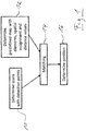
- Fig. 1 depicts a block diagram of a method for determining the position of a vehicle.
- the method can be carried out by a computer system of the vehicle (not shown).
- a plurality of scans are determined, each of the scans comprising a plurality of detection points.
- a predefined map is determined from a database, wherein the map comprises a plurality of elements, each of the elements representing a static landmark.
- the database is stored in a non-transitory storage medium of the computer system.
- the elements of the map are assumed to be formed by lines. However, other types of elements are also possible.
- the database comprises map data for a large area, wherein the map is determined by taking a portion of the map data, which corresponds to a preliminary position of the vehicle.
- the map comprises lines in a map environment, which corresponds to a current vehicle environment.
- the map also comprises a spatial assignment of parts of the map environment to the elements of the map.
- the map environment is represented by a plurality of positions (e.g. a grid), wherein each of the positions is assigned a line of the map.
- the positions are potential positions of detection points of the scans.
- the map further comprises a distance value for each of the positions. The distance values give the minimum distance between the positions and the assigned lines, respectively. This will be described further with respect to Fig. 2 and Fig. 3 .
- mapping is carried out between the detection points and the elements of the map.
- the spatial assignment of the predefined map is used for the matching and allows for carrying out the matching with high efficiency.
- the corresponding position in the map environment is identified, which can comprise one or more rounding operations of one or more coordinates of the detection point to coordinates of the nearest position in the map environment.
- Other ways of identifying the position are also possible.
- the element being assigned to the position is also assigned to the detection point. No exhaustive search through all elements of the map is necessary. Instead, the nearest element for a given detection point can readily be identified using the spatial assignment, which is part of the predetermined map.
- the current position of vehicle is determined on the basis of the matching. This can comprise updating the preliminary position with information from the matching, in particular a rigid transformation function.
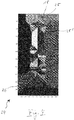
- Fig. 2 shows two exemplary detection points P and P', which are assigned to an element 18 of the map.
- the element 18 is considered to be the nearest element for both detection points P and P'.
- the element 18 is a line segment S, which extends between a first endpoint L min (i.e. startpoint) and a second endpoint L max .
- the distance between the detection point P and the line S is the Euclidean distance d(P), which is the minimum distance between P and S (orthogonal projection).
- the minimum distance is d(P'), as shown in Fig. 2 , which is the distance between P' and the end or corner point L max .
- the minimum distance calculation can be expressed by formula 20 shown in Fig. 3 .
- the first case of formula 20 describes the orthogonal projection, as for detection point P in Fig. 2 .
- the second case of formula 20 describes the minimum distance to one of the endpoints, as for the detection point P' in Fig. 2 .
- Formula 20 is used to compute a spatial assignment between parts of the map and the elements of the map, for example the element 18.
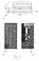
- Fig. 4 shows an exemplary map 24 comprising a plurality of elements, for example element 18, in a map environment 26.
- the map environment 26 is divided into spatial segments 28, which are shown in different grey scales in Fig. 4 and which form parts of the map environment 26.
- the spatial segments are shown without grey scales in Fig. 5 , see segments 28 and 28' for example.
- the spatial segments are assigned to the lines in the map environment 26, respectively.
- the spatial segment 28 is assigned to line 18, which is the line with the minimum distance to all points within the spatial segment 28.
- the spatial segments 28 can be determined offline (e.g. before carrying out the method described in Fig.
- the line 18 is readily determined as the nearest line from all lines of the map by using the spatial assignment of the map. Additionally, the distance value d is known from the map. Matching can then be carried out between detection points and the assigned lines, wherein the overall matching process is very efficient due to the spatial assignment and the distance values, which forms pre-computed data.
- the matching 14 comprises determining a rigid transformation function by minimizing the expression 22 of Fig. 3 .
- Expression 22 is a double sum over N lines of the map and M detection points d i . This corresponds to a least squares estimator for rotation R and translation t, wherein the j-th line is parameterized by the normal vector n j and the orthogonal distance b j between the j-th line and the origin.
- the expression f(p ij ) denotes an exponential weighting factor for the matching and depends on the probability p ij of detection point d i being assigned to the j-th line.
- the weighting factor can be used instead of a hard 0-1 assignment from the spatial assignment. This leads to an improved accuracy of the matching and hence to an improved accuracy of the determined position.
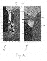
- the generation of K samples is illustrated in Fig. 7 showing the map portion 32', which corresponds to the map portion 32 from Fig. 6 discussed further below.
- a point cloud 38 is shown in the figure and represents K random samples drawn from the distribution. The distribution is represented by a propagated Gaussian error ellipse 40.
- An enlarged portion 36 is also shown in Fig. 7 . It is understood that by using the spatial assignment the samples 38 will be assigned to different lines because the samples 38 are located in different spatial segments. In this way, the probabilities p ij can be determined as described.
- Fig. 6 shows a portion 30 of the map 24 with lines of the map 24, for example line 18.
- the lines represent the walls of a parking garage level.
- the portion 30 can also be regarded as the map 24, wherein the spatial assignment is an additional layer or portion of this map.
- Another portion 32 of the map 24 is shown in Fig. 6 , which corresponds to the map 24 of Fig. 4 with colored spatial segments but without the lines.
- Fig. 6 includes another portion 34 of the map 24 representing distance values between the map environment 26 and the lines as color intensity, i.e. for a given point in the map portion 34 the color intensity indicates the distance to the nearest line according to formula 20. The distance values form another additional layer of the map 24.
Priority Applications (4)
| Application Number | Priority Date | Filing Date | Title |
|---|---|---|---|
| EP19212492.3A EP3828587A1 (de) | 2019-11-29 | 2019-11-29 | Verfahren zur bestimmung der position eines fahrzeugs |
| US17/093,357 US11506511B2 (en) | 2019-11-29 | 2020-11-09 | Method for determining the position of a vehicle |
| CN202011346481.3A CN112880694B (zh) | 2019-11-29 | 2020-11-26 | 确定车辆的位置的方法 |
| US18/047,678 US20230054783A1 (en) | 2019-11-29 | 2022-10-19 | Method for Determining the Position of a Vehicle |
Applications Claiming Priority (1)
| Application Number | Priority Date | Filing Date | Title |
|---|---|---|---|
| EP19212492.3A EP3828587A1 (de) | 2019-11-29 | 2019-11-29 | Verfahren zur bestimmung der position eines fahrzeugs |
Publications (1)
| Publication Number | Publication Date |
|---|---|
| EP3828587A1 true EP3828587A1 (de) | 2021-06-02 |
Family
ID=68732898
Family Applications (1)
| Application Number | Title | Priority Date | Filing Date |
|---|---|---|---|
| EP19212492.3A Pending EP3828587A1 (de) | 2019-11-29 | 2019-11-29 | Verfahren zur bestimmung der position eines fahrzeugs |
Country Status (3)
| Country | Link |
|---|---|
| US (2) | US11506511B2 (de) |
| EP (1) | EP3828587A1 (de) |
| CN (1) | CN112880694B (de) |
Families Citing this family (4)
| Publication number | Priority date | Publication date | Assignee | Title |
|---|---|---|---|---|
| EP3517996B1 (de) | 2018-01-25 | 2022-09-07 | Aptiv Technologies Limited | Verfahren zur bestimmung der position eines fahrzeugs |
| EP3518001B1 (de) | 2018-01-25 | 2020-09-16 | Aptiv Technologies Limited | Verfahren zur erhöhung der zuverlässigkeit der bestimmung der position eines fahrzeugs auf basis einer vielzahl von detektionspunkten |
| CN113776533A (zh) * | 2021-07-29 | 2021-12-10 | 北京旷视科技有限公司 | 可移动设备的重定位方法及装置 |
| CN117490727B (zh) * | 2023-12-27 | 2024-03-29 | 合众新能源汽车股份有限公司 | 定位精度评价方法、装置和电子设备 |
Citations (2)
| Publication number | Priority date | Publication date | Assignee | Title |
|---|---|---|---|---|
| DE102016214030A1 (de) * | 2016-07-29 | 2018-02-01 | Volkswagen Aktiengesellschaft | Verfahren und System zum Erfassen eines Verkehrsumfeldes einer mobilen Einheit |
| EP3517996A1 (de) * | 2018-01-25 | 2019-07-31 | Aptiv Technologies Limited | Verfahren zur bestimmung der position eines fahrzeugs |
Family Cites Families (35)
| Publication number | Priority date | Publication date | Assignee | Title |
|---|---|---|---|---|
| US4948258A (en) * | 1988-06-27 | 1990-08-14 | Harbor Branch Oceanographic Institute, Inc. | Structured illumination surface profiling and ranging systems and methods |
| DE10148062A1 (de) | 2001-09-28 | 2003-04-10 | Ibeo Automobile Sensor Gmbh | Verfahren zur Verarbeitung eines tiefenaufgelösten Bildes |
| US20060184488A1 (en) * | 2002-07-12 | 2006-08-17 | Chroma Energy, Inc. | Method and system for trace aligned and trace non-aligned pattern statistical calculation in seismic analysis |
| DE102004027693A1 (de) | 2004-04-08 | 2005-10-27 | Daimlerchrysler Ag | Verfahren zum Steuern von Insassenrückhaltemitteln und Steuereinheit für Insassenrückhaltemittel in einem Fahrzeug |
| US7095312B2 (en) | 2004-05-19 | 2006-08-22 | Accurate Technologies, Inc. | System and method for tracking identity movement and location of sports objects |
| US20070028220A1 (en) * | 2004-10-15 | 2007-02-01 | Xerox Corporation | Fault detection and root cause identification in complex systems |
| US7961137B2 (en) * | 2008-11-10 | 2011-06-14 | The Boeing Company | System and method for detecting performance of a sensor field at all points within a geographic area of regard |
| WO2011023244A1 (en) | 2009-08-25 | 2011-03-03 | Tele Atlas B.V. | Method and system of processing data gathered using a range sensor |
| JP5596368B2 (ja) | 2010-02-23 | 2014-09-24 | 富士通テン株式会社 | レーダ装置、物体検知システム、および、物体検知方法 |
| US8558733B2 (en) | 2010-03-15 | 2013-10-15 | Honda Elesys Co., Ltd. | Radar apparatus and computer program |
| EP2369899A1 (de) * | 2010-03-25 | 2011-09-28 | Koninklijke Philips Electronics N.V. | Verfahren zum Steuern eines Außenbeleuchtungssystems, Computerprogrammprodukt, Steuerungsvorrichtung und Außenbeleuchtungssystem |
| JP5503578B2 (ja) | 2011-03-10 | 2014-05-28 | パナソニック株式会社 | 物体検出装置及び物体検出方法 |
| FR2974421B1 (fr) | 2011-04-21 | 2014-02-21 | Thales Sa | Procede pour detecter, sur plusieurs tours d'antenne, des cibles lentes noyees dans le fouillis radar avec un radar mobile a antenne rotative |
| US9140792B2 (en) * | 2011-06-01 | 2015-09-22 | GM Global Technology Operations LLC | System and method for sensor based environmental model construction |
| DE102012106932A1 (de) | 2012-07-30 | 2014-05-15 | Continental Teves Ag & Co. Ohg | Verfahren zur Darstellung einer Fahrzeugumgebung mit Positionspunkten |
| JP6020321B2 (ja) | 2013-04-11 | 2016-11-02 | 株式会社デンソー | 物標検出装置及び車両制御システム |
| CN103278170B (zh) * | 2013-05-16 | 2016-01-06 | 东南大学 | 基于显著场景点检测的移动机器人级联地图创建方法 |
| US9199643B1 (en) | 2014-09-25 | 2015-12-01 | GM Global Technology Operations LLC | Sensor odometry and application in crash avoidance vehicle |
| DE102014223363B4 (de) | 2014-11-17 | 2021-04-29 | Volkswagen Aktiengesellschaft | Verfahren und Vorrichtung zur Lokalisation eines Kraftfahrzeugs in einer ortsfesten Referenzkarte |
| CN105115497B (zh) * | 2015-09-17 | 2018-07-24 | 南京大学 | 一种可靠的室内移动机器人精确导航定位系统及方法 |
| DE102016205227A1 (de) | 2016-03-30 | 2017-10-05 | Astyx Gmbh | Verfahren und Vorrichtung zur Verfolgung von Objekten, insbesondere sich bewegenden Objekten, in den dreidimensionalen Raum von abbildenden Radarsensoren |
| US10989542B2 (en) * | 2016-03-11 | 2021-04-27 | Kaarta, Inc. | Aligning measured signal data with slam localization data and uses thereof |
| US10802450B2 (en) | 2016-09-08 | 2020-10-13 | Mentor Graphics Corporation | Sensor event detection and fusion |
| US20180283882A1 (en) * | 2017-04-04 | 2018-10-04 | Appropolis Inc. | Location-based services system and method therefor |
| US10657804B2 (en) * | 2017-08-11 | 2020-05-19 | Here Global B.V. | Updating maps and road status |
| EP3518001B1 (de) | 2018-01-25 | 2020-09-16 | Aptiv Technologies Limited | Verfahren zur erhöhung der zuverlässigkeit der bestimmung der position eines fahrzeugs auf basis einer vielzahl von detektionspunkten |
| IT201800006594A1 (it) * | 2018-06-22 | 2019-12-22 | "Procedimento per la mappatura dell’ambiente di un veicolo, corrispondenti sistema, veicolo e prodotto informatico" | |
| US10782136B2 (en) * | 2018-09-28 | 2020-09-22 | Zoox, Inc. | Modifying map elements associated with map data |
| US11580687B2 (en) * | 2018-12-04 | 2023-02-14 | Ottopia Technologies Ltd. | Transferring data from autonomous vehicles |
| CN111366164B (zh) | 2018-12-26 | 2023-12-29 | 华为技术有限公司 | 定位方法及电子设备 |
| WO2020188671A1 (ja) * | 2019-03-18 | 2020-09-24 | 三菱電機株式会社 | 地図情報補正装置、移動体、地図情報作成装置、地図情報補正システム、地図情報補正方法および地図情報補正プログラム |
| EP4022254A4 (de) * | 2019-10-04 | 2023-09-06 | Waymo Llc | Räumlich-zeitliche posen-/objektdatenbank |
| DE102019128253A1 (de) * | 2019-10-18 | 2021-04-22 | StreetScooter GmbH | Verfahren zum Navigieren eines Flurförderzeugs |
| EP3819663A1 (de) | 2019-11-07 | 2021-05-12 | Aptiv Technologies Limited | Verfahren zur bestimmung der position eines fahrzeugs |
| EP3851870A1 (de) | 2020-01-14 | 2021-07-21 | Aptiv Technologies Limited | Verfahren zur bestimmung von positionsdaten und/oder bewegungsdaten eines fahrzeugs |
-
2019
- 2019-11-29 EP EP19212492.3A patent/EP3828587A1/de active Pending
-
2020
- 2020-11-09 US US17/093,357 patent/US11506511B2/en active Active
- 2020-11-26 CN CN202011346481.3A patent/CN112880694B/zh active Active
-
2022
- 2022-10-19 US US18/047,678 patent/US20230054783A1/en active Pending
Patent Citations (2)
| Publication number | Priority date | Publication date | Assignee | Title |
|---|---|---|---|---|
| DE102016214030A1 (de) * | 2016-07-29 | 2018-02-01 | Volkswagen Aktiengesellschaft | Verfahren und System zum Erfassen eines Verkehrsumfeldes einer mobilen Einheit |
| EP3517996A1 (de) * | 2018-01-25 | 2019-07-31 | Aptiv Technologies Limited | Verfahren zur bestimmung der position eines fahrzeugs |
Non-Patent Citations (3)
| Title |
|---|
| BUR-NIKEL, CHRISTOPHKURT MEHLHORNSTEFAN SCHIRRA: "European Symposium on Algorithms", 1994, SPRINGER, article "How to compute the Voronoi diagram of line segments: Theoretical and experimental results" |
| BUR-NIKEL, CHRISTOPHKURT MEHLHORNSTEFAN SCHIRRA: "European Symposium on Algorithms", 1994, SPRINGER, article "How to compute the Voronoi diagram of line segments: Theoretical and experimental results", XP002799038 * |
| SCHWERTFEGER SÖREN ET AL: "Map evaluation using matched topology graphs", AUTONOMOUS ROBOTS, KLUWER ACADEMIC PUBLISHERS, DORDRECHT, NL, vol. 40, no. 5, 3 September 2015 (2015-09-03), pages 761 - 787, XP035822436, ISSN: 0929-5593, [retrieved on 20150903], DOI: 10.1007/S10514-015-9493-5 * |
Also Published As
| Publication number | Publication date |
|---|---|
| US20210164800A1 (en) | 2021-06-03 |
| CN112880694B (zh) | 2024-04-16 |
| US20230054783A1 (en) | 2023-02-23 |
| US11506511B2 (en) | 2022-11-22 |
| CN112880694A (zh) | 2021-06-01 |
Similar Documents
| Publication | Publication Date | Title |
|---|---|---|
| US11506511B2 (en) | Method for determining the position of a vehicle | |
| US9625908B2 (en) | Methods and systems for mobile-agent navigation | |
| CN107341819B (zh) | 目标跟踪方法及存储介质 | |
| US9495602B2 (en) | Image and map-based detection of vehicles at intersections | |
| CN110082747B (zh) | 基于多个检测点来增加确定车辆位置的可靠性的方法 | |
| US8558679B2 (en) | Method of analyzing the surroundings of a vehicle | |
| CN110082753B (zh) | 确定车辆位置的方法 | |
| KR102547274B1 (ko) | 이동 로봇 및 이의 위치 인식 방법 | |
| US20210141091A1 (en) | Method for Determining a Position of a Vehicle | |
| EP3851870A1 (de) | Verfahren zur bestimmung von positionsdaten und/oder bewegungsdaten eines fahrzeugs | |
| CN111220167A (zh) | 应用地图以改善目标跟踪、车道分配和分类的系统和方法 | |
| US20220176989A1 (en) | High precision position estimation method through road shape classification-based map matching and autonomous vehicle thereof | |
| EP3842836A1 (de) | Verfahren, vorrichtung und speichermedium zum positionieren von objekten | |
| CN114879660B (zh) | 一种基于目标驱动的机器人环境感知方法 | |
| Groh et al. | Advanced real-time indoor parking localization based on semi-static objects | |
| Burger et al. | Unstructured road slam using map predictive road tracking | |
| Song et al. | Critical rays self-adaptive particle filtering SLAM | |
| CN115061499A (zh) | 无人机控制方法及无人机控制装置 | |
| Pishehvari et al. | Radar scan matching using navigation maps | |
| Muravyev et al. | Evaluation of Topological Mapping Methods in Indoor Environments | |
| Burger et al. | Map-Aware SLAM with Sparse Map Features | |
| CN117570998B (zh) | 基于反光柱信息的机器人定位方法及系统 | |
| Thallas et al. | Particle filter—Scan matching SLAM recovery under kinematic model failures | |
| KR102275671B1 (ko) | 객체 형태 검출 장치 및 방법 | |
| Xu et al. | Uncertainty aware EKF: a tracking filter learning LiDAR measurement uncertainty |
Legal Events
| Date | Code | Title | Description |
|---|---|---|---|
| PUAI | Public reference made under article 153(3) epc to a published international application that has entered the european phase |
Free format text: ORIGINAL CODE: 0009012 |
|
| STAA | Information on the status of an ep patent application or granted ep patent |
Free format text: STATUS: THE APPLICATION HAS BEEN PUBLISHED |
|
| AK | Designated contracting states |
Kind code of ref document: A1 Designated state(s): AL AT BE BG CH CY CZ DE DK EE ES FI FR GB GR HR HU IE IS IT LI LT LU LV MC MK MT NL NO PL PT RO RS SE SI SK SM TR |
|
| STAA | Information on the status of an ep patent application or granted ep patent |
Free format text: STATUS: REQUEST FOR EXAMINATION WAS MADE |
|
| 17P | Request for examination filed |
Effective date: 20211202 |
|
| RBV | Designated contracting states (corrected) |
Designated state(s): AL AT BE BG CH CY CZ DE DK EE ES FI FR GB GR HR HU IE IS IT LI LT LU LV MC MK MT NL NO PL PT RO RS SE SI SK SM TR |
|
| RAP3 | Party data changed (applicant data changed or rights of an application transferred) |
Owner name: APTIV TECHNOLOGIES LIMITED |
|
| STAA | Information on the status of an ep patent application or granted ep patent |
Free format text: STATUS: EXAMINATION IS IN PROGRESS |
|
| 17Q | First examination report despatched |
Effective date: 20231120 |