EP3819663A1 - Verfahren zur bestimmung der position eines fahrzeugs - Google Patents
Verfahren zur bestimmung der position eines fahrzeugs Download PDFInfo
- Publication number
- EP3819663A1 EP3819663A1 EP19207813.7A EP19207813A EP3819663A1 EP 3819663 A1 EP3819663 A1 EP 3819663A1 EP 19207813 A EP19207813 A EP 19207813A EP 3819663 A1 EP3819663 A1 EP 3819663A1
- Authority
- EP
- European Patent Office
- Prior art keywords
- sensor data
- sensor
- vehicle
- map
- determining
- Prior art date
- Legal status (The legal status is an assumption and is not a legal conclusion. Google has not performed a legal analysis and makes no representation as to the accuracy of the status listed.)
- Pending
Links
- 238000000034 method Methods 0.000 title claims abstract description 48
- 230000001131 transforming effect Effects 0.000 claims abstract description 14
- 230000009466 transformation Effects 0.000 claims description 32
- 230000003068 static effect Effects 0.000 claims description 10
- 230000008859 change Effects 0.000 claims description 9
- 230000005670 electromagnetic radiation Effects 0.000 claims description 2
- 238000010801 machine learning Methods 0.000 claims description 2
- 230000005855 radiation Effects 0.000 claims description 2
- 230000004044 response Effects 0.000 claims description 2
- 238000010586 diagram Methods 0.000 description 32
- 230000033001 locomotion Effects 0.000 description 29
- 230000006870 function Effects 0.000 description 20
- 238000005259 measurement Methods 0.000 description 16
- 238000012545 processing Methods 0.000 description 14
- 238000001514 detection method Methods 0.000 description 11
- 239000013598 vector Substances 0.000 description 4
- 238000013500 data storage Methods 0.000 description 3
- 230000004807 localization Effects 0.000 description 3
- 238000013459 approach Methods 0.000 description 2
- 238000004590 computer program Methods 0.000 description 2
- 238000013528 artificial neural network Methods 0.000 description 1
- 230000004888 barrier function Effects 0.000 description 1
- 230000006399 behavior Effects 0.000 description 1
- 238000007796 conventional method Methods 0.000 description 1
- 238000001914 filtration Methods 0.000 description 1
- 238000000691 measurement method Methods 0.000 description 1
- 230000003287 optical effect Effects 0.000 description 1
- 230000008569 process Effects 0.000 description 1
- 238000011524 similarity measure Methods 0.000 description 1
- 239000007787 solid Substances 0.000 description 1
- 238000013519 translation Methods 0.000 description 1
Images


Classifications
-
- G—PHYSICS
- G01—MEASURING; TESTING
- G01C—MEASURING DISTANCES, LEVELS OR BEARINGS; SURVEYING; NAVIGATION; GYROSCOPIC INSTRUMENTS; PHOTOGRAMMETRY OR VIDEOGRAMMETRY
- G01C21/00—Navigation; Navigational instruments not provided for in groups G01C1/00 - G01C19/00
- G01C21/26—Navigation; Navigational instruments not provided for in groups G01C1/00 - G01C19/00 specially adapted for navigation in a road network
- G01C21/28—Navigation; Navigational instruments not provided for in groups G01C1/00 - G01C19/00 specially adapted for navigation in a road network with correlation of data from several navigational instruments
-
- G—PHYSICS
- G01—MEASURING; TESTING
- G01S—RADIO DIRECTION-FINDING; RADIO NAVIGATION; DETERMINING DISTANCE OR VELOCITY BY USE OF RADIO WAVES; LOCATING OR PRESENCE-DETECTING BY USE OF THE REFLECTION OR RERADIATION OF RADIO WAVES; ANALOGOUS ARRANGEMENTS USING OTHER WAVES
- G01S7/00—Details of systems according to groups G01S13/00, G01S15/00, G01S17/00
- G01S7/02—Details of systems according to groups G01S13/00, G01S15/00, G01S17/00 of systems according to group G01S13/00
- G01S7/41—Details of systems according to groups G01S13/00, G01S15/00, G01S17/00 of systems according to group G01S13/00 using analysis of echo signal for target characterisation; Target signature; Target cross-section
- G01S7/415—Identification of targets based on measurements of movement associated with the target
-
- G—PHYSICS
- G01—MEASURING; TESTING
- G01S—RADIO DIRECTION-FINDING; RADIO NAVIGATION; DETERMINING DISTANCE OR VELOCITY BY USE OF RADIO WAVES; LOCATING OR PRESENCE-DETECTING BY USE OF THE REFLECTION OR RERADIATION OF RADIO WAVES; ANALOGOUS ARRANGEMENTS USING OTHER WAVES
- G01S17/00—Systems using the reflection or reradiation of electromagnetic waves other than radio waves, e.g. lidar systems
- G01S17/86—Combinations of lidar systems with systems other than lidar, radar or sonar, e.g. with direction finders
-
- G—PHYSICS
- G01—MEASURING; TESTING
- G01C—MEASURING DISTANCES, LEVELS OR BEARINGS; SURVEYING; NAVIGATION; GYROSCOPIC INSTRUMENTS; PHOTOGRAMMETRY OR VIDEOGRAMMETRY
- G01C21/00—Navigation; Navigational instruments not provided for in groups G01C1/00 - G01C19/00
- G01C21/10—Navigation; Navigational instruments not provided for in groups G01C1/00 - G01C19/00 by using measurements of speed or acceleration
- G01C21/12—Navigation; Navigational instruments not provided for in groups G01C1/00 - G01C19/00 by using measurements of speed or acceleration executed aboard the object being navigated; Dead reckoning
- G01C21/16—Navigation; Navigational instruments not provided for in groups G01C1/00 - G01C19/00 by using measurements of speed or acceleration executed aboard the object being navigated; Dead reckoning by integrating acceleration or speed, i.e. inertial navigation
- G01C21/165—Navigation; Navigational instruments not provided for in groups G01C1/00 - G01C19/00 by using measurements of speed or acceleration executed aboard the object being navigated; Dead reckoning by integrating acceleration or speed, i.e. inertial navigation combined with non-inertial navigation instruments
-
- G—PHYSICS
- G01—MEASURING; TESTING
- G01C—MEASURING DISTANCES, LEVELS OR BEARINGS; SURVEYING; NAVIGATION; GYROSCOPIC INSTRUMENTS; PHOTOGRAMMETRY OR VIDEOGRAMMETRY
- G01C21/00—Navigation; Navigational instruments not provided for in groups G01C1/00 - G01C19/00
- G01C21/26—Navigation; Navigational instruments not provided for in groups G01C1/00 - G01C19/00 specially adapted for navigation in a road network
- G01C21/28—Navigation; Navigational instruments not provided for in groups G01C1/00 - G01C19/00 specially adapted for navigation in a road network with correlation of data from several navigational instruments
- G01C21/30—Map- or contour-matching
-
- G—PHYSICS
- G01—MEASURING; TESTING
- G01C—MEASURING DISTANCES, LEVELS OR BEARINGS; SURVEYING; NAVIGATION; GYROSCOPIC INSTRUMENTS; PHOTOGRAMMETRY OR VIDEOGRAMMETRY
- G01C21/00—Navigation; Navigational instruments not provided for in groups G01C1/00 - G01C19/00
- G01C21/26—Navigation; Navigational instruments not provided for in groups G01C1/00 - G01C19/00 specially adapted for navigation in a road network
- G01C21/34—Route searching; Route guidance
- G01C21/36—Input/output arrangements for on-board computers
- G01C21/3602—Input other than that of destination using image analysis, e.g. detection of road signs, lanes, buildings, real preceding vehicles using a camera
-
- G—PHYSICS
- G01—MEASURING; TESTING
- G01S—RADIO DIRECTION-FINDING; RADIO NAVIGATION; DETERMINING DISTANCE OR VELOCITY BY USE OF RADIO WAVES; LOCATING OR PRESENCE-DETECTING BY USE OF THE REFLECTION OR RERADIATION OF RADIO WAVES; ANALOGOUS ARRANGEMENTS USING OTHER WAVES
- G01S13/00—Systems using the reflection or reradiation of radio waves, e.g. radar systems; Analogous systems using reflection or reradiation of waves whose nature or wavelength is irrelevant or unspecified
- G01S13/02—Systems using reflection of radio waves, e.g. primary radar systems; Analogous systems
- G01S13/50—Systems of measurement based on relative movement of target
- G01S13/58—Velocity or trajectory determination systems; Sense-of-movement determination systems
-
- G—PHYSICS
- G01—MEASURING; TESTING
- G01S—RADIO DIRECTION-FINDING; RADIO NAVIGATION; DETERMINING DISTANCE OR VELOCITY BY USE OF RADIO WAVES; LOCATING OR PRESENCE-DETECTING BY USE OF THE REFLECTION OR RERADIATION OF RADIO WAVES; ANALOGOUS ARRANGEMENTS USING OTHER WAVES
- G01S13/00—Systems using the reflection or reradiation of radio waves, e.g. radar systems; Analogous systems using reflection or reradiation of waves whose nature or wavelength is irrelevant or unspecified
- G01S13/66—Radar-tracking systems; Analogous systems
- G01S13/72—Radar-tracking systems; Analogous systems for two-dimensional tracking, e.g. combination of angle and range tracking, track-while-scan radar
- G01S13/723—Radar-tracking systems; Analogous systems for two-dimensional tracking, e.g. combination of angle and range tracking, track-while-scan radar by using numerical data
-
- G—PHYSICS
- G01—MEASURING; TESTING
- G01S—RADIO DIRECTION-FINDING; RADIO NAVIGATION; DETERMINING DISTANCE OR VELOCITY BY USE OF RADIO WAVES; LOCATING OR PRESENCE-DETECTING BY USE OF THE REFLECTION OR RERADIATION OF RADIO WAVES; ANALOGOUS ARRANGEMENTS USING OTHER WAVES
- G01S13/00—Systems using the reflection or reradiation of radio waves, e.g. radar systems; Analogous systems using reflection or reradiation of waves whose nature or wavelength is irrelevant or unspecified
- G01S13/87—Combinations of radar systems, e.g. primary radar and secondary radar
- G01S13/876—Combination of several spaced transponders or reflectors of known location for determining the position of a receiver
-
- G—PHYSICS
- G01—MEASURING; TESTING
- G01S—RADIO DIRECTION-FINDING; RADIO NAVIGATION; DETERMINING DISTANCE OR VELOCITY BY USE OF RADIO WAVES; LOCATING OR PRESENCE-DETECTING BY USE OF THE REFLECTION OR RERADIATION OF RADIO WAVES; ANALOGOUS ARRANGEMENTS USING OTHER WAVES
- G01S13/00—Systems using the reflection or reradiation of radio waves, e.g. radar systems; Analogous systems using reflection or reradiation of waves whose nature or wavelength is irrelevant or unspecified
- G01S13/88—Radar or analogous systems specially adapted for specific applications
- G01S13/89—Radar or analogous systems specially adapted for specific applications for mapping or imaging
-
- G—PHYSICS
- G01—MEASURING; TESTING
- G01S—RADIO DIRECTION-FINDING; RADIO NAVIGATION; DETERMINING DISTANCE OR VELOCITY BY USE OF RADIO WAVES; LOCATING OR PRESENCE-DETECTING BY USE OF THE REFLECTION OR RERADIATION OF RADIO WAVES; ANALOGOUS ARRANGEMENTS USING OTHER WAVES
- G01S13/00—Systems using the reflection or reradiation of radio waves, e.g. radar systems; Analogous systems using reflection or reradiation of waves whose nature or wavelength is irrelevant or unspecified
- G01S13/88—Radar or analogous systems specially adapted for specific applications
- G01S13/93—Radar or analogous systems specially adapted for specific applications for anti-collision purposes
- G01S13/931—Radar or analogous systems specially adapted for specific applications for anti-collision purposes of land vehicles
-
- G—PHYSICS
- G01—MEASURING; TESTING
- G01S—RADIO DIRECTION-FINDING; RADIO NAVIGATION; DETERMINING DISTANCE OR VELOCITY BY USE OF RADIO WAVES; LOCATING OR PRESENCE-DETECTING BY USE OF THE REFLECTION OR RERADIATION OF RADIO WAVES; ANALOGOUS ARRANGEMENTS USING OTHER WAVES
- G01S17/00—Systems using the reflection or reradiation of electromagnetic waves other than radio waves, e.g. lidar systems
- G01S17/02—Systems using the reflection of electromagnetic waves other than radio waves
- G01S17/06—Systems determining position data of a target
- G01S17/46—Indirect determination of position data
-
- G—PHYSICS
- G01—MEASURING; TESTING
- G01S—RADIO DIRECTION-FINDING; RADIO NAVIGATION; DETERMINING DISTANCE OR VELOCITY BY USE OF RADIO WAVES; LOCATING OR PRESENCE-DETECTING BY USE OF THE REFLECTION OR RERADIATION OF RADIO WAVES; ANALOGOUS ARRANGEMENTS USING OTHER WAVES
- G01S17/00—Systems using the reflection or reradiation of electromagnetic waves other than radio waves, e.g. lidar systems
- G01S17/02—Systems using the reflection of electromagnetic waves other than radio waves
- G01S17/50—Systems of measurement based on relative movement of target
- G01S17/58—Velocity or trajectory determination systems; Sense-of-movement determination systems
-
- G—PHYSICS
- G01—MEASURING; TESTING
- G01S—RADIO DIRECTION-FINDING; RADIO NAVIGATION; DETERMINING DISTANCE OR VELOCITY BY USE OF RADIO WAVES; LOCATING OR PRESENCE-DETECTING BY USE OF THE REFLECTION OR RERADIATION OF RADIO WAVES; ANALOGOUS ARRANGEMENTS USING OTHER WAVES
- G01S17/00—Systems using the reflection or reradiation of electromagnetic waves other than radio waves, e.g. lidar systems
- G01S17/66—Tracking systems using electromagnetic waves other than radio waves
-
- G—PHYSICS
- G01—MEASURING; TESTING
- G01S—RADIO DIRECTION-FINDING; RADIO NAVIGATION; DETERMINING DISTANCE OR VELOCITY BY USE OF RADIO WAVES; LOCATING OR PRESENCE-DETECTING BY USE OF THE REFLECTION OR RERADIATION OF RADIO WAVES; ANALOGOUS ARRANGEMENTS USING OTHER WAVES
- G01S17/00—Systems using the reflection or reradiation of electromagnetic waves other than radio waves, e.g. lidar systems
- G01S17/88—Lidar systems specially adapted for specific applications
- G01S17/89—Lidar systems specially adapted for specific applications for mapping or imaging
-
- G—PHYSICS
- G01—MEASURING; TESTING
- G01S—RADIO DIRECTION-FINDING; RADIO NAVIGATION; DETERMINING DISTANCE OR VELOCITY BY USE OF RADIO WAVES; LOCATING OR PRESENCE-DETECTING BY USE OF THE REFLECTION OR RERADIATION OF RADIO WAVES; ANALOGOUS ARRANGEMENTS USING OTHER WAVES
- G01S17/00—Systems using the reflection or reradiation of electromagnetic waves other than radio waves, e.g. lidar systems
- G01S17/88—Lidar systems specially adapted for specific applications
- G01S17/93—Lidar systems specially adapted for specific applications for anti-collision purposes
- G01S17/931—Lidar systems specially adapted for specific applications for anti-collision purposes of land vehicles
-
- G—PHYSICS
- G01—MEASURING; TESTING
- G01S—RADIO DIRECTION-FINDING; RADIO NAVIGATION; DETERMINING DISTANCE OR VELOCITY BY USE OF RADIO WAVES; LOCATING OR PRESENCE-DETECTING BY USE OF THE REFLECTION OR RERADIATION OF RADIO WAVES; ANALOGOUS ARRANGEMENTS USING OTHER WAVES
- G01S7/00—Details of systems according to groups G01S13/00, G01S15/00, G01S17/00
- G01S7/02—Details of systems according to groups G01S13/00, G01S15/00, G01S17/00 of systems according to group G01S13/00
- G01S7/28—Details of pulse systems
- G01S7/285—Receivers
- G01S7/295—Means for transforming co-ordinates or for evaluating data, e.g. using computers
- G01S7/2955—Means for determining the position of the radar coordinate system for evaluating the position data of the target in another coordinate system
-
- G—PHYSICS
- G01—MEASURING; TESTING
- G01S—RADIO DIRECTION-FINDING; RADIO NAVIGATION; DETERMINING DISTANCE OR VELOCITY BY USE OF RADIO WAVES; LOCATING OR PRESENCE-DETECTING BY USE OF THE REFLECTION OR RERADIATION OF RADIO WAVES; ANALOGOUS ARRANGEMENTS USING OTHER WAVES
- G01S7/00—Details of systems according to groups G01S13/00, G01S15/00, G01S17/00
- G01S7/48—Details of systems according to groups G01S13/00, G01S15/00, G01S17/00 of systems according to group G01S17/00
- G01S7/483—Details of pulse systems
- G01S7/484—Transmitters
-
- G—PHYSICS
- G01—MEASURING; TESTING
- G01S—RADIO DIRECTION-FINDING; RADIO NAVIGATION; DETERMINING DISTANCE OR VELOCITY BY USE OF RADIO WAVES; LOCATING OR PRESENCE-DETECTING BY USE OF THE REFLECTION OR RERADIATION OF RADIO WAVES; ANALOGOUS ARRANGEMENTS USING OTHER WAVES
- G01S7/00—Details of systems according to groups G01S13/00, G01S15/00, G01S17/00
- G01S7/48—Details of systems according to groups G01S13/00, G01S15/00, G01S17/00 of systems according to group G01S17/00
- G01S7/497—Means for monitoring or calibrating
-
- G—PHYSICS
- G01—MEASURING; TESTING
- G01S—RADIO DIRECTION-FINDING; RADIO NAVIGATION; DETERMINING DISTANCE OR VELOCITY BY USE OF RADIO WAVES; LOCATING OR PRESENCE-DETECTING BY USE OF THE REFLECTION OR RERADIATION OF RADIO WAVES; ANALOGOUS ARRANGEMENTS USING OTHER WAVES
- G01S7/00—Details of systems according to groups G01S13/00, G01S15/00, G01S17/00
- G01S7/52—Details of systems according to groups G01S13/00, G01S15/00, G01S17/00 of systems according to group G01S15/00
- G01S7/539—Details of systems according to groups G01S13/00, G01S15/00, G01S17/00 of systems according to group G01S15/00 using analysis of echo signal for target characterisation; Target signature; Target cross-section
-
- G—PHYSICS
- G01—MEASURING; TESTING
- G01S—RADIO DIRECTION-FINDING; RADIO NAVIGATION; DETERMINING DISTANCE OR VELOCITY BY USE OF RADIO WAVES; LOCATING OR PRESENCE-DETECTING BY USE OF THE REFLECTION OR RERADIATION OF RADIO WAVES; ANALOGOUS ARRANGEMENTS USING OTHER WAVES
- G01S13/00—Systems using the reflection or reradiation of radio waves, e.g. radar systems; Analogous systems using reflection or reradiation of waves whose nature or wavelength is irrelevant or unspecified
- G01S13/02—Systems using reflection of radio waves, e.g. primary radar systems; Analogous systems
- G01S13/50—Systems of measurement based on relative movement of target
- G01S13/58—Velocity or trajectory determination systems; Sense-of-movement determination systems
- G01S13/589—Velocity or trajectory determination systems; Sense-of-movement determination systems measuring the velocity vector
-
- G—PHYSICS
- G01—MEASURING; TESTING
- G01S—RADIO DIRECTION-FINDING; RADIO NAVIGATION; DETERMINING DISTANCE OR VELOCITY BY USE OF RADIO WAVES; LOCATING OR PRESENCE-DETECTING BY USE OF THE REFLECTION OR RERADIATION OF RADIO WAVES; ANALOGOUS ARRANGEMENTS USING OTHER WAVES
- G01S13/00—Systems using the reflection or reradiation of radio waves, e.g. radar systems; Analogous systems using reflection or reradiation of waves whose nature or wavelength is irrelevant or unspecified
- G01S13/86—Combinations of radar systems with non-radar systems, e.g. sonar, direction finder
- G01S13/865—Combination of radar systems with lidar systems
-
- G—PHYSICS
- G01—MEASURING; TESTING
- G01S—RADIO DIRECTION-FINDING; RADIO NAVIGATION; DETERMINING DISTANCE OR VELOCITY BY USE OF RADIO WAVES; LOCATING OR PRESENCE-DETECTING BY USE OF THE REFLECTION OR RERADIATION OF RADIO WAVES; ANALOGOUS ARRANGEMENTS USING OTHER WAVES
- G01S13/00—Systems using the reflection or reradiation of radio waves, e.g. radar systems; Analogous systems using reflection or reradiation of waves whose nature or wavelength is irrelevant or unspecified
- G01S13/86—Combinations of radar systems with non-radar systems, e.g. sonar, direction finder
- G01S13/867—Combination of radar systems with cameras
-
- G—PHYSICS
- G01—MEASURING; TESTING
- G01S—RADIO DIRECTION-FINDING; RADIO NAVIGATION; DETERMINING DISTANCE OR VELOCITY BY USE OF RADIO WAVES; LOCATING OR PRESENCE-DETECTING BY USE OF THE REFLECTION OR RERADIATION OF RADIO WAVES; ANALOGOUS ARRANGEMENTS USING OTHER WAVES
- G01S13/00—Systems using the reflection or reradiation of radio waves, e.g. radar systems; Analogous systems using reflection or reradiation of waves whose nature or wavelength is irrelevant or unspecified
- G01S13/88—Radar or analogous systems specially adapted for specific applications
- G01S13/93—Radar or analogous systems specially adapted for specific applications for anti-collision purposes
- G01S13/931—Radar or analogous systems specially adapted for specific applications for anti-collision purposes of land vehicles
- G01S2013/932—Radar or analogous systems specially adapted for specific applications for anti-collision purposes of land vehicles using own vehicle data, e.g. ground speed, steering wheel direction
-
- G—PHYSICS
- G01—MEASURING; TESTING
- G01S—RADIO DIRECTION-FINDING; RADIO NAVIGATION; DETERMINING DISTANCE OR VELOCITY BY USE OF RADIO WAVES; LOCATING OR PRESENCE-DETECTING BY USE OF THE REFLECTION OR RERADIATION OF RADIO WAVES; ANALOGOUS ARRANGEMENTS USING OTHER WAVES
- G01S13/00—Systems using the reflection or reradiation of radio waves, e.g. radar systems; Analogous systems using reflection or reradiation of waves whose nature or wavelength is irrelevant or unspecified
- G01S13/88—Radar or analogous systems specially adapted for specific applications
- G01S13/93—Radar or analogous systems specially adapted for specific applications for anti-collision purposes
- G01S13/931—Radar or analogous systems specially adapted for specific applications for anti-collision purposes of land vehicles
- G01S2013/9323—Alternative operation using light waves
-
- G—PHYSICS
- G01—MEASURING; TESTING
- G01S—RADIO DIRECTION-FINDING; RADIO NAVIGATION; DETERMINING DISTANCE OR VELOCITY BY USE OF RADIO WAVES; LOCATING OR PRESENCE-DETECTING BY USE OF THE REFLECTION OR RERADIATION OF RADIO WAVES; ANALOGOUS ARRANGEMENTS USING OTHER WAVES
- G01S13/00—Systems using the reflection or reradiation of radio waves, e.g. radar systems; Analogous systems using reflection or reradiation of waves whose nature or wavelength is irrelevant or unspecified
- G01S13/88—Radar or analogous systems specially adapted for specific applications
- G01S13/93—Radar or analogous systems specially adapted for specific applications for anti-collision purposes
- G01S13/931—Radar or analogous systems specially adapted for specific applications for anti-collision purposes of land vehicles
- G01S2013/9327—Sensor installation details
- G01S2013/93271—Sensor installation details in the front of the vehicles
-
- G—PHYSICS
- G01—MEASURING; TESTING
- G01S—RADIO DIRECTION-FINDING; RADIO NAVIGATION; DETERMINING DISTANCE OR VELOCITY BY USE OF RADIO WAVES; LOCATING OR PRESENCE-DETECTING BY USE OF THE REFLECTION OR RERADIATION OF RADIO WAVES; ANALOGOUS ARRANGEMENTS USING OTHER WAVES
- G01S13/00—Systems using the reflection or reradiation of radio waves, e.g. radar systems; Analogous systems using reflection or reradiation of waves whose nature or wavelength is irrelevant or unspecified
- G01S13/88—Radar or analogous systems specially adapted for specific applications
- G01S13/93—Radar or analogous systems specially adapted for specific applications for anti-collision purposes
- G01S13/931—Radar or analogous systems specially adapted for specific applications for anti-collision purposes of land vehicles
- G01S2013/9327—Sensor installation details
- G01S2013/93274—Sensor installation details on the side of the vehicles
-
- G—PHYSICS
- G01—MEASURING; TESTING
- G01S—RADIO DIRECTION-FINDING; RADIO NAVIGATION; DETERMINING DISTANCE OR VELOCITY BY USE OF RADIO WAVES; LOCATING OR PRESENCE-DETECTING BY USE OF THE REFLECTION OR RERADIATION OF RADIO WAVES; ANALOGOUS ARRANGEMENTS USING OTHER WAVES
- G01S7/00—Details of systems according to groups G01S13/00, G01S15/00, G01S17/00
- G01S7/003—Transmission of data between radar, sonar or lidar systems and remote stations
-
- G—PHYSICS
- G01—MEASURING; TESTING
- G01S—RADIO DIRECTION-FINDING; RADIO NAVIGATION; DETERMINING DISTANCE OR VELOCITY BY USE OF RADIO WAVES; LOCATING OR PRESENCE-DETECTING BY USE OF THE REFLECTION OR RERADIATION OF RADIO WAVES; ANALOGOUS ARRANGEMENTS USING OTHER WAVES
- G01S7/00—Details of systems according to groups G01S13/00, G01S15/00, G01S17/00
- G01S7/02—Details of systems according to groups G01S13/00, G01S15/00, G01S17/00 of systems according to group G01S13/00
- G01S7/41—Details of systems according to groups G01S13/00, G01S15/00, G01S17/00 of systems according to group G01S13/00 using analysis of echo signal for target characterisation; Target signature; Target cross-section
- G01S7/417—Details of systems according to groups G01S13/00, G01S15/00, G01S17/00 of systems according to group G01S13/00 using analysis of echo signal for target characterisation; Target signature; Target cross-section involving the use of neural networks
Definitions
- the present disclosure relates to a computer-implemented method for determining a position of a vehicle.
- Vehicles known from the state of the art are capable of determining their current position on the basis of at least one sensor mounted on the vehicle.
- many vehicles comprise a global-positioning system (GPS) from which the position of the vehicle can be inferred with a fair degree of accuracy.
- GPS global-positioning system
- the determination of the position by means of a GPS requires a radio signal from the satellite space, which is, however, not always readily available.
- the required GPS-signal can be very weak so that a relatively long time span is necessary in order to evaluate the position from the signal.
- the signal is too weak in order to securely determine the position.
- there is even no signal available for example, in fully or partially enclosed vicinities, such as road tunnels and buildings, in particular subterranean garages. Therefore, no position can be determined at all.
- the accuracy of GPS is sometimes not sufficient, for example for autonomous-driving applications.
- Modern vehicles for example upper-class cars, are equipped with radar and/or LiDAR (light detection and ranging) systems.
- Corresponding measurements i.e. scans
- various measurement methods e.g., odometry (dead reckoning) are alone not suitable for determining the position with the desired reliability.
- using radar sensors or comparable sensor technology requires significant processing resources, for example due to determining radar detection points from the raw sensor data.
- the raw sensor data is usually given as sensor data samples with a radial distance component and a rate of change of the distance (velocity in the radial distance direction). Such sensor data can be denoted as Doppler-sensor data.
- the present disclosure provides a computer-implemented method, a computer system and a non-transitory computer readable medium according to the independent claims. Embodiments are given in the subclaims, the description and the drawings.
- the present disclosure is directed at a computer-implemented method for determining a position of a vehicle, wherein the vehicle is equipped with at least one sensor for capturing scans of a vicinity of the vehicle, wherein the method comprises at least the following steps carried out by computer-hardware components: capturing at least one scan by means of the at least one sensor, wherein the at least one scan represents the vicinity of the vehicle and comprises a plurality of sensor data samples given in a sensor data representation, wherein the sensor data representation comprises a first component and a second component, the first component representing a distance between the sensor and the vicinity of the vehicle, and the second component representing a rate of change of the distance between the sensor and the vicinity of the vehicle; determining, from a database, a predefined map, wherein the predefined map represents the vicinity of the vehicle and comprises at least one element representing a static landmark, wherein the at least one element is given in a map data representation comprising a plurality of coordinates, wherein the coordinates represent position information of the static landmark; determining a
- sensor measurements for example radar measurements
- determining the position of the vehicle on the basis of radar scans can require significant processing efforts.
- a radar scan usually comprises a plethora of sensor data samples from which only a portion represent useful measurements, e.g., due to noise.
- the sensor data samples are not provided in a full spatial representation like a Cartesian coordinate system.
- the sensor data samples are given with said first component (distance) and second component (rate of change of distance), which is only a partial spatial representation.
- radar detection points also called point cloud
- the detection points could be determined from the sensor data samples, which involves processing (e.g., peak finding, angle estimation, transformation from Polar to Cartesian coordinates).
- the detection points could then be used for matching because map data and detection points would then both be provided in a full spatial representation, e.g. Cartesian coordinates.
- the detection points can comprise full spatial information relative to the underlying vehicle.
- ground-truth data which represents the vicinity of the vehicle.
- This ground-truth data is provided in form of a database, which comprises map data that preferably represents a geo-structural model.
- the map data describes the vicinity of a desired driving area, which preferably comprises characteristic objects, i.e. static landmarks, which can limit a desired driving area of a vehicle. Examples for such landmarks are traffic signs, poles, street lamps, walls, fences but also substantial pavement edges and bigger plants, e.g., trees and the like.
- the map data is not limited thereto. This is to say that the map data can also comprise landmarks, which are not directly relevant for defining an allowable driving space.
- the map data can comprise descriptions of those objects which will be sensed by the sensor in its vicinity.
- the map data stored in the database comprises representations of static landmarks in form of so-called elements.
- elements are of mathematical nature and are preferably simplified objects, as will be explained in greater detail below.
- each of the elements comprises information about its global position, i.e. in a world coordinate system, which can be a Cartesian coordinate system.
- sensor data samples acquired by means of a sensor e.g. radar system of a vehicle, only comprise two components, which represent a relative distance between the vicinity and the sensor and the rate of change of the distance (velocity). This forms at least a part of the sensor data representation.
- the map data in the database can comprise map data, which captures a desired driving area, for example all valid driving areas in a given country or a group of different countries. From this map data a predefined map is determined, wherein the predefined map can be limited to a current vicinity of the vehicle. This current vicinity can be limited to a specified range of the sensor so that the predefined map includes only those elements within the range, i.e., those objects which are potentially hit by the sensor signals emitted from the sensor. Therefore, the step of determining the predefined map comprises identifying a portion of the map which corresponds to a current "view" of the sensor, thereby providing a geo-structural description of the local vicinity of the vehicle at a given time instant.
- the predefined map can be determined on the basis of position information derived from a current GPS-signal received at the vehicle. If such a signal is currently not available the last GPS-signal or another position estimate may be used, in particular from one or more motion sensors of the vehicle. It is understood that the validity of the predefined map as ground truth depends on the validity of the position information that is used for determining the current map. If a position estimate from one or more motion sensors of the vehicle is used (odometry), the predefined map can be regarded as an inaccurate estimation, wherein the sensor data samples are regarded as ground truth. The matching can then be used to find an improved position estimate.
- Each of the plurality of elements of the predefined map represents a static landmark in the vicinity of the vehicle.
- the predefined map can be a navigation map, in particular a navigation map from a publicly available database, e.g. open-street map.
- the predefined map can be derived from a global database on the basis of a given position of the vehicle, e.g. from a global position system of the vehicle or by using odometry, as indicated above.
- the static landmarks can be static objects, e.g. poles, walls of buildings or other barriers for the vehicle which form objects detectable by the sensor system of the vehicle.
- the map can be a so called High-Definition (HD) map in which the elements are provided with highly precise position information.
- HD High-Definition
- the predefined map i.e. the at least one element thereof, is matched with at least a subset of the plurality of sensor data samples.
- the plurality of sensor data samples are acquired by means of one or more scans, wherein in the latter case, the scans are preferably successive scans.
- the sensor data samples correspond to a substantially common time instant, which may also be a short time span.
- the term "matching" can be understood in the sense of evaluating a correspondence between the sensor data samples and the one or more elements.
- the sensor data samples - as a ground truth - can be used to find a location with an increased certainty (i.e., the sensor data samples are used to reduce the uncertainty with respect to transformed elements).
- the matching can be a registration process, for example an image registration.
- the position of the vehicle is determined on the basis of the matching. This is to say that the correspondence between the sensor data samples and the transformed elements is exploited for determining the position.
- the position can be determined from any appropriate sensor measurement or a combination thereof.
- the combination proposed here namely sensor data samples and transformed elements, can be sufficient to determine the position.
- the matching allows increasing the accuracy of the position determination.
- additional sensor measurements can be used for determining the position, e.g., from one or more additional sensors of the vehicle.
- the position of the vehicle comprises coordinates, which represent a location of the vehicle with respect to a coordinate system.
- the position can comprise an angle of the vehicle representing a heading, i.e. an orientation of the vehicle with respect to a reference heading.
- the method can be implemented in a vehicle in order to provide one or more autonomous-driving applications requiring accurate information about a current position of the vehicle. This is to say that the driving behaviour of the vehicle (i.e. “the vehicle”) is controlled or modified with respect to the determined position of the vehicle.
- the sensor data representation is a native data representation of the sensor and/or wherein the plurality of sensor data samples form raw sensor data of the sensor. Processing overhead for determining data, which is derived from the raw data, such as radar detection points, can thus be avoided.
- the first component represents a radial distance between the sensor and the vicinity of the vehicle
- the second component represents a rate of change, in particular velocity, of the radial distance between the sensor and the vicinity of the vehicle (radial velocity)
- the sensor data representation preferably does not comprise a component representing an angle information.
- the first and second component can be directly obtained per sensor data sample when using a radar system for example. An angle, which is usually part of any radar detection point, does not need to be evaluated and the corresponding processing overhead can be saved.
- the sensor comprises a Doppler sensor, in particular a radar sensor and/or a LiDAR (light detection and ranging) sensor.
- a vision sensor for example a camera can be used for obtaining sensor data samples in the sensor data representation.
- Doppler sensor indicates that it the sensor is configured to obtain sensor data samples directly in the sensor data representation. Determining the sensor data samples can nevertheless require some data processing, but it is deemed to be much less than for determining proper detection points with a full spatial representation in two dimensions. For example, processing an emitted radar signal and a received radar signal in order to determine the distance and the rate of change of the distance is much less complex than determining angle information from the sensor data of a radar sensor.
- the senor in particular when being configured as a radar sensor, comprises only a single receiver, in particular a single antenna. This is in contrast to usual radar sensors comprising multiple antennas in order to allow angle information to be determined from the corresponding sensor data.
- angle information is preferably not determined in the method described herein, a single antenna or receiver sensor is sufficient and hardware costs of the sensor can be significantly reduced.
- transforming the at least one element comprises using a predefined transformation rule, the transformation rule being adapted to receive the at least one element of the predefined map and velocity information of the sensor and/or the vehicle and to output the at least one element of the transformed map in the sensor data representation in response.
- the predefined transformation rule can receive an initial estimate of the position of the vehicle, for example based on motion sensors of the vehicle (odometry) or GPS.
- the plurality of coordinates of the map data representation are associated with a Cartesian coordinate system or a Polar coordinate system.
- Other spatial coordinate systems can also be adopted.
- the at least one element represents a pole object, in particular stationary road equipment, for example a street lamp pole or a traffic sign pole. Good results can be achieved with pole objects. However, other types are also possible.
- the method further comprises determining a subset of the sensor data samples on the basis of the at least one element of the transformed map. In this way, the amount of data is significantly reduced to a portion, which is likely to correlate with the elements of the map.
- determining the subset of the sensor data samples is carried out by using a predefined classification rule, in particular a machine-learning based classification rule, for example on the basis of an artificial neural network. Additionally or alternatively, signal processing approaches like filtering of the sensor data samples can be used to determine the subset.
- the method further comprises determining a subset of the sensor data samples to be matched, wherein the following steps are carried out for at least some of the sensor data samples: identifying, from the plurality of sensor data samples, a sensor data sample having maximum similarity with the at least one element of the transformed map; and assigning the identified sensor data sample to the at least one element of the transformed map.
- the similarity with the at least one element can be determined for at least some, in particular all of the sensor data samples.
- the similarity can be determined by evaluating a similarity measure, which can be a distance measure, for example an Euclidean distance measure. The distance measure represents the difference between the first and second components of the respective sensor data sample and the respective element.
- identifying the sensor data sample comprises: determining candidate sensor data samples from the plurality of sensor data samples, wherein each of the candidate sensor data samples is located in a predefined neighbourhood of the at least one element of the transformed map, the predefined neighbourhood being defined with respect to the first component and the second component of the sensor data representation; determining, for each candidate sensor data sample, a difference between the candidate sensor data sample and the at least one element of the transformed map; and selecting the sensor data sample having the minimum difference.
- maximum similarity corresponds with a minimal difference.
- the difference can be determined as the Euclidean distance with respect to the first and second component, as also mentioned before.
- the matching comprises determining a rigid transformation function by minimizing a difference between the at least one element and the assigned sensor data sample, wherein one of the element and the assigned sensor data sample is transformed by means of the rigid transformation function.
- the at least one element of the transformed map is transformed by the rigid transformation function, i.e. the element is matched to the respective data sample.
- the method further comprises determining a preliminary position of the vehicle, and wherein determining the position of the vehicle comprises transforming the preliminary position by means of the rigid transformation function.
- the method further comprises determining the position, in particular the preliminary position, on the basis of a motion model of the vehicle, wherein the motion model is determined on the basis of at least one measurement from at least one motion sensor of the vehicle and/or on the basis of at least some of the plurality of data samples of the at least one scan.
- the motion model can be a model which describes the trajectory of the vehicle over time.
- the model can be initialized with some value and is then periodically updated based on motion measurements of the vehicle.
- the motion model is preferably determined on the basis of at least one measurement from at least one motion sensor of the vehicle and/or on the basis of at least some of the sensor data samples.
- the combination of measurements from a motion sensor and a radar system can further enhance the accuracy of the method.
- a suitable localization system can be used, for example on the basis of a DGPS (Differential Global Positioning System).
- the measurement from the at least one motion sensor can comprise a velocity and/or a yaw rate of the vehicle, wherein the vehicle preferably comprises corresponding sensor facilities.
- This is also known as "dead-reckoning" measurements.
- the velocity and/or the yaw rate of the vehicle is determined on the basis of wheel-speed-sensor (wheel rotation per time span) measurements and/or yaw-rate-sensor measurements.
- Dead-reckoning measurements taken alone have been found to provide inaccurate estimations of the vehicle position under certain conditions, e.g., during strong steering manewins. For this reason, the estimation based on dead-reckoning can represent a preliminary estimation of the vehicle's position.
- the position of the vehicle can comprise coordinates representing a location and an orientation of the vehicle.
- the present disclosure is directed at a computer system, said computer system being configured to carry out several or all steps of the computer implemented method described herein.
- the computer system can be connected or connectable to a sensor or sensor system of a vehicle, wherein the sensor or sensor system can be configured to perform at least the method step of capturing the at least one scan with the sensor data samples given in the sensor data represention.
- the sensor can be part of a sensor unit, which can be a radar sensor unit or a LiDAR sensor unit.
- the computer system can be configured to perform other method steps disclosed herein, in particular determining the predefined map, transforming the map, matching and/or determining the position. Related method steps can also be performed by the computer system.
- the computer system can also be connected or connectable to motion sensors of the vehicle or to a localization system in order to determine a preliminary position of the vehicle, for example by using a motion model of the vehicle.
- the computer system can be formed or can be part of a computing unit or system of the vehicle, for example an electronic control unit (ECU) of the vehicle.
- the computer system may comprise a processing unit, at least one memory unit and at least one non-transitory data storage.
- the non-transitory data storage and/or the memory unit may comprise a computer program for instructing the computer to perform several or all steps or aspects of the computer implemented method described herein.
- the present disclosure is directed at a vehicle equipped with a sensor system, wherein the sensor system is adapted to receive electromagnetic radiation emitted from at least one emitter of the sensor system and reflected in a vicinity of the vehicle towards the sensor system, and a computer system for determining a position of the vehicle on the basis of the emitted and the reflected radiation.
- the present disclosure is directed at a non-transitory computer readable medium comprising instructions for carrying out several or all steps or aspects of the computer-implemented method described herein.
- the computer readable medium may be configured as: an optical medium, such as a compact disc (CD) or a digital versatile disk (DVD); a magnetic medium, such as a hard disk drive (HDD); a solid state drive (SSD); a read only memory (ROM), such as a flash memory; or the like.
- the computer readable medium may be configured as a data storage that is accessible via a data connection, such as an internet connection.
- the computer readable medium may, for example, be an online data repository or a cloud storage.
- the present disclosure is also directed at a computer program for instructing a computer to perform several or all steps or aspects of the computer-implemented method described herein.
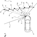
- Fig. 1 depicts a vehicle 10, wherein a Doppler sensor 12 is mounted at the left side of the front bumper of the vehicle 10.
- the Doppler sensor 12 is configured as a radar sensor with a field of view indicated by reference numeral 14.
- the sensor 12 is configured to determine scans of the vicinity 16, wherein a plurality of poles 18 are located in the vicinity 16.
- the sensor 12 has a range, which is suitable to detect each of the poles 18 within the field of view 14, as will be explained in more detail.
- the sensor 12 moves with a sensor velocity 24 (v s ), which is due to a movement of the vehicle 10 at which the sensor 12 is mounted.
- the poles 18 are all stationary and represent for example stationary road equipment objects such as traffic lights or the like.
- the sensor velocity 24 can be described with respect to an x-coordinate dimension 20 (x ISO ) and a y-coordinate dimension 22 (y ISO ), which form a coordinate system of the sensor 12, as indicated in Fig. 1 .
- the sensor velocity 24 can be split up into portions v x and v y of the dimensions 20 and 22.
- the poles 18 can be considered to move with an inverse sensor velocity 26, which is indicated as corresponding vector arrows originating from the poles 18, cf. Fig. 1 .
- This interpretation results if one assumes that the sensor 12 is stationary, i.e. the relative movement between the sensor 12 and the poles 18 is assigned to the poles 18 rather than to the sensor 12.
- the sensor 12 is configured to determine sensor data samples, wherein each of the sensor data samples has a first component and a second component. These components are illustrated in Fig. 1 for each of the poles 18, which are considered to produce a corresponding sensor data sample for each of the poles 18.
- the first component is radial distance 30 and the second component is radial velocity 28, which is the rate of change of the distance 30.
- the radial distance 30 corresponds to the minimum distance between the sensor 12 (the origin of the sensor coordinate system or another reference point of the sensor) and a respective pole 18, wherein the distance 30 is indicated as dashed line.
- the radial velocity 28 is indicated in Fig. 1 as an arrow extending from the pole 18 towards the direction of the radial velocity 28.
- the length of the arrow indicates the magnitude of the velocity 28. It is understood from Fig. 1 that as the angle ⁇ between the distance 30 and the sensor-velocity vector 24 increases the difference between the radial velocity 28 and the inverse sensor velocity 26 increases. This makes clear that radial velocity 28 is a measured velocity from the perspective of the sensor 12 and it can happen that the radial velocity 28 is close to zero despite a significant sensor velocity 24. It is understood that the scan comprises many more sensor data samples from the vicinity 16, wherein not each sensor data sample represents a pole as indicated in Fig. 1 . This means that the scan can comprise data samples, which represent background characteristics of the vicinity 16.
- the poles 18 from Fig. 1 are represented by elements of a predefined map of the vicinity 16 (not explicitly shown).
- the elements are transformed from the map data representation to the sensor data representation.
- the sensor data representation comprises two components representing radial distance 30 and radial velocity 28.
- the map data representation has spatial coordinate dimensions, in particular Cartesian coordinate dimensions.
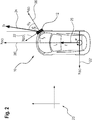
- the elements are transformed on the basis of a current estimated vehicle position and motion information of the vehicle 10. This is done by using a predefined transformation rule, which is further illustrated in Fig. 2 .
- a coordinate system with an x-coordinate dimension 20' and a y-coordinate dimension 22' is placed with its origin in the middle of the rear axis of the vehicle 10.
- the position of the vehicle 10 is assumed to be known with respect to to the world or map coordinate system 23, which is the same spatial domain as for the elements of the predefined map.
- the vehicle velocity v and the yaw rate ⁇ are measured with respect to the vehicle coordinate system defined by the dimensions 20', 22', cf. Fig. 2 .
- the x-coordinate l x and the y-coordinate l y of the position of the sensor 12 with respect to the dimensions 20' and 22' are known.
- the mounting angle ⁇ s is known.
- each of the elements of the predefined map can be readily transformed into the sensor data representation.
- transformed elements are described by means of the radial distance 30 and a radial velocity 28, as indicated in Fig. 1 .
- the transformed elements can now be processed together with the actual sensor data, i.e. the sensor data samples, wherein the transformed elements and the actual sensor data are both given in the sensor data representation. In this way, a complex processing of the sensor data samples can be avoided.
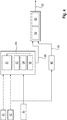
- Block 40 represents determining the predefined map comprising a plurality of elements, wherein each of the elements represents a static landmark in the vicinity of the vehicle, for example the poles 18 in the vicinity 16 of the vehicle 10, as shown in Fig. 1 .
- the elements are given in a map data representation, as discussed in view of Fig. 1 and Fig. 2 .
- Block 42 represents determining the vehicle motion, for example the velocity v and the yaw rate ⁇ , wherein motion sensors of the vehicle are used, as discussed in connection with Fig. 2 .
- Block 44 represents determining at least one scan of the vehicle's vicinity, wherein the scan comprises a plurality of sensor data samples given in the sensor data representation, as discussed in connection with Fig. 1 .
- the vehicle motion parameters obtained from block 42 are fed into block 46, which represent a motion model or another localization system (e.g., DGPS) of the vehicle.
- the motion model is used to determine a preliminary position 48 of the vehicle, which is assumed to be inaccurate with respect to the true position of the vehicle.
- the predefined map from block 40 and the vehicle motion parameters from block 42 are fed into block 50, which represents transforming the elements of the map into the sensor data representation, as discussed in connection with Fig. 2 .
- the transformed elements can be considered to represent a simulated map because the elements are transformed into virtual sensor data samples.
- the method steps of blocks 52, 54, and 56 are carried out on the basis of the transformed elements from block 50 and the true sensor data samples from block 44.
- the most similar sensor data sample from block 44 is identified for each of the transformed elements from block 50. This may be done by identifying candidate sensor data samples from block 44 within a neighbourhood of a respective transformed element, wherein the candidate sensor data sample having a minimum difference with the element is selected as the most similar sensor data sample.
- the neigbourhood is defined by fixed thresholds for each of the first and second component of the sensor data representation. For example, when a respective element has component values (de, ve) the neigbourhood can be defined by intervals [de-d1, de+d1] for the first component and [ve-v1, ve+v1] for the second component.
- the most similar sensor data sample from block 44 is assigned to the respective transformed element from block 50.
- a rigid transformation function is determined by minimizing a cost function that describes the mismatch between the transformed elements from block 50 and the assigned sensor data samples.
- the cost function involves transforming the transformed elements from block 50 by means of the rigid transformation function, wherein the rigid transformation function comprises a transformation parameter for the first component of the sensor data representation and another transformation parameter for the second component of the sensor data representation.
- the transformation parameters 58 are transformed into the map data representation in block 59, which may comprise parameters for translation in x and y dimensions and an angle for rotation.
- the preliminary position 48 is transformed by means of the transformation parameters 58 of the rigid transformation function given in the map data representation.
- the resulting final position of the vehicle 62 is then considered to be more accurate than the preliminary position 48.
- the block diagram of Fig. 4 illustrates an extension of the method described in view of Fig. 3 , namely the use of a plurality of sensors mounted at the same vehicle.
- a loop 64 is implemented, wherein the method steps described in connection with blocks 50, 52, 54, and 56 are carried out for each of the plurality of sensors.
- the determination of the rigid transformation function in block 56 takes into account the mismatch between the transformed elements for each of the sensors and the corresponding assigned sensor data samples. In this way, the parameters of the rigid transformation function 58 can be considered to be even more accurate so that the accuracy of the determined position 62 can be further increased in the sense of fusing the data of the plurality of sensors.
- Fig. 5 comprises two diagrams 66 and 68.
- Diagram 68 comprises a plurality of sensor data samples 74 given in the sensor data representation, which comprises a first component, namely a distance velocity component 70 (Doppler), and a second component, namely distance component 72. It is understood that the component 72 represents a radial distance 30 illustrated in Fig. 1 . Likewise, component 70 represents a radial velocity 28 as also shown in Fig. 1 .
- the sensor data samples 74 represent the poles 18 from Fig.
- sensor data samples 74' are shown in the map data representation in diagram 66 in Fig. 5 .
- vehicle 10 is also shown in diagram 66.
- the x-coordinate dimension 20' and the y-coordinate dimension 22' of diagram 66 correspond to the dimensions shown in Fig. 2 with respect to the vehicle 10.
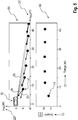
- Fig. 6 comprises diagrams 82 and 84, which generally correspond to diagrams 66 and 68 from Fig. 5 .
- diagram 84 comprises transformed elements 78, which represent the poles 18 as elements from the predefined map in the sensor data representation.
- the untransformed elements 76 are plotted in diagram 82, i.e. with respect to the dimensions 20' and 22', wherein inverse velocity vectors 26 and radial velocity vectors 28 are shown for illustrative purposes.
- a vehicle 10' is shown in overlay with the vehicle 10 from Fig. 5 , wherein the position of vehicle 10' corresponds to the inaccurate position 48 discussed in connection with Fig. 3 and Fig. 4 .
- a mismatch between vehicle 10 and the vehicle 10' corresponds to the mismatch of the sensor data samples 74 and the transformed elements 78.
- the point-like nature of the sensor data samples 74 in Fig. 6 does not necessarily correspond to the true shape of the sensor data.
- the sensor data sample 74 can be blurred or spread along one or both of the components 70 and 72.
- a plurality of sensor data samples 74 can be located around each of the transformed elements 78, which are indicated as crosses in diagram 84 of Fig. 6 .
- diagram 84 shows a situation, wherein the most similar sensor data sample 74 has already been assigned to the nearest elements 78, which corresponds to the outcome of block 54 in Fig. 3 and Fig. 4 .
- the rigid transformation function is then determined by minimizing a difference or mismatch between the sensor data samples 74 and the transformed elements 78 with the optimum parameter set 58 for the rigid transformation function.
- Fig. 7 shows diagrams 86 and 88 that generally correspond to diagrams 82 and 84 from Fig. 6 after the matching.
- the elements 78 from diagram 84 are transformed with the optimum parameter set 58 by means of the rigid transformation function.
- diagram 86 it can be seen that there is no mismatch between vehicles 10 and 10'. This means that the position of vehicle 10', which corresponds to the inaccurate position 48, has been transformed with the optimum parameter set 58 by means of the rigid transformation function.
- the processing effort required for carrying out the described method is much lower than with conventional methods, which involve transforming the sensor data samples 74 provided by the sensor 12 into a full spatial representation, for example with respect to the x-coordinate dimension 20' and the y-coordinate dimension 22'. This is because the sensor 12 provides huge amounts of data samples. In contrast, the number of elements 76 of the predefined map is much lower and therefore the processing effort for transforming these elements from the map data representation into the sensor data representation is much lower.
Landscapes
- Engineering & Computer Science (AREA)
- Remote Sensing (AREA)
- Radar, Positioning & Navigation (AREA)
- Physics & Mathematics (AREA)
- General Physics & Mathematics (AREA)
- Computer Networks & Wireless Communication (AREA)
- Electromagnetism (AREA)
- Automation & Control Theory (AREA)
- Computer Vision & Pattern Recognition (AREA)
- Navigation (AREA)
- Traffic Control Systems (AREA)
- Radar Systems Or Details Thereof (AREA)
Priority Applications (3)
| Application Number | Priority Date | Filing Date | Title |
|---|---|---|---|
| EP19207813.7A EP3819663A1 (de) | 2019-11-07 | 2019-11-07 | Verfahren zur bestimmung der position eines fahrzeugs |
| US17/087,560 US11977159B2 (en) | 2019-11-07 | 2020-11-02 | Method for determining a position of a vehicle |
| CN202011221747.1A CN112781599B (zh) | 2019-11-07 | 2020-11-05 | 确定车辆的位置的方法 |
Applications Claiming Priority (1)
| Application Number | Priority Date | Filing Date | Title |
|---|---|---|---|
| EP19207813.7A EP3819663A1 (de) | 2019-11-07 | 2019-11-07 | Verfahren zur bestimmung der position eines fahrzeugs |
Publications (1)
| Publication Number | Publication Date |
|---|---|
| EP3819663A1 true EP3819663A1 (de) | 2021-05-12 |
Family
ID=68502977
Family Applications (1)
| Application Number | Title | Priority Date | Filing Date |
|---|---|---|---|
| EP19207813.7A Pending EP3819663A1 (de) | 2019-11-07 | 2019-11-07 | Verfahren zur bestimmung der position eines fahrzeugs |
Country Status (3)
| Country | Link |
|---|---|
| US (1) | US11977159B2 (de) |
| EP (1) | EP3819663A1 (de) |
| CN (1) | CN112781599B (de) |
Cited By (1)
| Publication number | Priority date | Publication date | Assignee | Title |
|---|---|---|---|---|
| DE102021004528A1 (de) | 2021-09-07 | 2021-10-28 | Daimler Ag | Verfahren zur Bestimmung einer Position eines Fahrzeugs |
Families Citing this family (5)
| Publication number | Priority date | Publication date | Assignee | Title |
|---|---|---|---|---|
| EP3518001B1 (de) | 2018-01-25 | 2020-09-16 | Aptiv Technologies Limited | Verfahren zur erhöhung der zuverlässigkeit der bestimmung der position eines fahrzeugs auf basis einer vielzahl von detektionspunkten |
| EP3517996B1 (de) | 2018-01-25 | 2022-09-07 | Aptiv Technologies Limited | Verfahren zur bestimmung der position eines fahrzeugs |
| EP3828587A1 (de) | 2019-11-29 | 2021-06-02 | Aptiv Technologies Limited | Verfahren zur bestimmung der position eines fahrzeugs |
| JP7290104B2 (ja) * | 2019-12-23 | 2023-06-13 | 株式会社デンソー | 自己位置推定装置、方法及びプログラム |
| EP3851870A1 (de) | 2020-01-14 | 2021-07-21 | Aptiv Technologies Limited | Verfahren zur bestimmung von positionsdaten und/oder bewegungsdaten eines fahrzeugs |
Citations (5)
| Publication number | Priority date | Publication date | Assignee | Title |
|---|---|---|---|---|
| DE10148062A1 (de) * | 2001-09-28 | 2003-04-10 | Ibeo Automobile Sensor Gmbh | Verfahren zur Verarbeitung eines tiefenaufgelösten Bildes |
| WO2011023244A1 (en) * | 2009-08-25 | 2011-03-03 | Tele Atlas B.V. | Method and system of processing data gathered using a range sensor |
| DE102016205227A1 (de) * | 2016-03-30 | 2017-10-05 | Astyx Gmbh | Verfahren und Vorrichtung zur Verfolgung von Objekten, insbesondere sich bewegenden Objekten, in den dreidimensionalen Raum von abbildenden Radarsensoren |
| US20180067491A1 (en) * | 2016-09-08 | 2018-03-08 | Mentor Graphics Corporation | Event classification and object tracking |
| EP3517996A1 (de) * | 2018-01-25 | 2019-07-31 | Aptiv Technologies Limited | Verfahren zur bestimmung der position eines fahrzeugs |
Family Cites Families (22)
| Publication number | Priority date | Publication date | Assignee | Title |
|---|---|---|---|---|
| US5181254A (en) * | 1990-12-14 | 1993-01-19 | Westinghouse Electric Corp. | Method for automatically identifying targets in sonar images |
| DE102004027693A1 (de) | 2004-04-08 | 2005-10-27 | Daimlerchrysler Ag | Verfahren zum Steuern von Insassenrückhaltemitteln und Steuereinheit für Insassenrückhaltemittel in einem Fahrzeug |
| US7095312B2 (en) | 2004-05-19 | 2006-08-22 | Accurate Technologies, Inc. | System and method for tracking identity movement and location of sports objects |
| CN101952688A (zh) * | 2008-02-04 | 2011-01-19 | 电子地图北美公司 | 用于与传感器检测到的对象进行地图匹配的方法 |
| JP5596368B2 (ja) | 2010-02-23 | 2014-09-24 | 富士通テン株式会社 | レーダ装置、物体検知システム、および、物体検知方法 |
| CN102221698B (zh) | 2010-03-15 | 2014-09-10 | 株式会社本田艾莱希斯 | 雷达设备 |
| JP5745067B2 (ja) * | 2010-09-24 | 2015-07-08 | アイロボット・コーポレーション | Vslam最適化のためのシステムおよび方法 |
| CN102069824B (zh) * | 2010-12-30 | 2013-03-13 | 北京交通大学 | 轨道交通车辆的定位装置和方法 |
| JP5503578B2 (ja) | 2011-03-10 | 2014-05-28 | パナソニック株式会社 | 物体検出装置及び物体検出方法 |
| FR2974421B1 (fr) | 2011-04-21 | 2014-02-21 | Thales Sa | Procede pour detecter, sur plusieurs tours d'antenne, des cibles lentes noyees dans le fouillis radar avec un radar mobile a antenne rotative |
| DE102012106932A1 (de) | 2012-07-30 | 2014-05-15 | Continental Teves Ag & Co. Ohg | Verfahren zur Darstellung einer Fahrzeugumgebung mit Positionspunkten |
| JP6020321B2 (ja) | 2013-04-11 | 2016-11-02 | 株式会社デンソー | 物標検出装置及び車両制御システム |
| US9199643B1 (en) | 2014-09-25 | 2015-12-01 | GM Global Technology Operations LLC | Sensor odometry and application in crash avoidance vehicle |
| DE102014223363B4 (de) | 2014-11-17 | 2021-04-29 | Volkswagen Aktiengesellschaft | Verfahren und Vorrichtung zur Lokalisation eines Kraftfahrzeugs in einer ortsfesten Referenzkarte |
| DE102016214030A1 (de) | 2016-07-29 | 2018-02-01 | Volkswagen Aktiengesellschaft | Verfahren und System zum Erfassen eines Verkehrsumfeldes einer mobilen Einheit |
| US20180136332A1 (en) * | 2016-11-15 | 2018-05-17 | Wheego Electric Cars, Inc. | Method and system to annotate objects and determine distances to objects in an image |
| US10422648B2 (en) * | 2017-10-17 | 2019-09-24 | AI Incorporated | Methods for finding the perimeter of a place using observed coordinates |
| EP3518001B1 (de) * | 2018-01-25 | 2020-09-16 | Aptiv Technologies Limited | Verfahren zur erhöhung der zuverlässigkeit der bestimmung der position eines fahrzeugs auf basis einer vielzahl von detektionspunkten |
| CN109100730B (zh) * | 2018-05-18 | 2022-05-24 | 北京师范大学-香港浸会大学联合国际学院 | 一种多车协同快速建图方法 |
| CN111366164B (zh) | 2018-12-26 | 2023-12-29 | 华为技术有限公司 | 定位方法及电子设备 |
| EP3828587A1 (de) | 2019-11-29 | 2021-06-02 | Aptiv Technologies Limited | Verfahren zur bestimmung der position eines fahrzeugs |
| EP3851870A1 (de) | 2020-01-14 | 2021-07-21 | Aptiv Technologies Limited | Verfahren zur bestimmung von positionsdaten und/oder bewegungsdaten eines fahrzeugs |
-
2019
- 2019-11-07 EP EP19207813.7A patent/EP3819663A1/de active Pending
-
2020
- 2020-11-02 US US17/087,560 patent/US11977159B2/en active Active
- 2020-11-05 CN CN202011221747.1A patent/CN112781599B/zh active Active
Patent Citations (5)
| Publication number | Priority date | Publication date | Assignee | Title |
|---|---|---|---|---|
| DE10148062A1 (de) * | 2001-09-28 | 2003-04-10 | Ibeo Automobile Sensor Gmbh | Verfahren zur Verarbeitung eines tiefenaufgelösten Bildes |
| WO2011023244A1 (en) * | 2009-08-25 | 2011-03-03 | Tele Atlas B.V. | Method and system of processing data gathered using a range sensor |
| DE102016205227A1 (de) * | 2016-03-30 | 2017-10-05 | Astyx Gmbh | Verfahren und Vorrichtung zur Verfolgung von Objekten, insbesondere sich bewegenden Objekten, in den dreidimensionalen Raum von abbildenden Radarsensoren |
| US20180067491A1 (en) * | 2016-09-08 | 2018-03-08 | Mentor Graphics Corporation | Event classification and object tracking |
| EP3517996A1 (de) * | 2018-01-25 | 2019-07-31 | Aptiv Technologies Limited | Verfahren zur bestimmung der position eines fahrzeugs |
Cited By (1)
| Publication number | Priority date | Publication date | Assignee | Title |
|---|---|---|---|---|
| DE102021004528A1 (de) | 2021-09-07 | 2021-10-28 | Daimler Ag | Verfahren zur Bestimmung einer Position eines Fahrzeugs |
Also Published As
| Publication number | Publication date |
|---|---|
| CN112781599A (zh) | 2021-05-11 |
| CN112781599B (zh) | 2024-06-07 |
| US11977159B2 (en) | 2024-05-07 |
| US20210141091A1 (en) | 2021-05-13 |
Similar Documents
| Publication | Publication Date | Title |
|---|---|---|
| US12005907B2 (en) | Method for determining position data and/or motion data of a vehicle | |
| US11977159B2 (en) | Method for determining a position of a vehicle | |
| US10698100B2 (en) | Method and device for determining the position of a vehicle | |
| US9298992B2 (en) | Geographic feature-based localization with feature weighting | |
| RU2720140C1 (ru) | Способ оценки собственной позиции и устройство оценки собственной позиции | |
| US20060220912A1 (en) | Sensing apparatus for vehicles | |
| US11506511B2 (en) | Method for determining the position of a vehicle | |
| JP7155284B2 (ja) | 計測精度算出装置、自己位置推定装置、制御方法、プログラム及び記憶媒体 | |
| Fortin et al. | A model-based joint detection and tracking approach for multi-vehicle tracking with lidar sensor | |
| GB2370706A (en) | Determining the position of a vehicle | |
| CN112578781B (zh) | 数据处理方法、装置、芯片系统及介质 | |
| Muresan et al. | Multimodal sparse LIDAR object tracking in clutter | |
| Rabe et al. | Ego-lane estimation for downtown lane-level navigation | |
| CN111198390A (zh) | 用于估算车辆位置的装置及方法 | |
| US20200062252A1 (en) | Method and apparatus for diagonal lane detection | |
| Lee et al. | Fast point cloud feature extraction for real-time slam | |
| CN114641701A (zh) | 使用表面穿透雷达和深度学习的改进的导航和定位 | |
| Pishehvari et al. | Robust range-doppler registration with hd maps | |
| Elfring et al. | Vehicle localization using a traffic sign map | |
| CN118405130B (zh) | 一种越野环境感知与跟踪引导车辆的方法、系统及介质 | |
| US11466991B2 (en) | Sensor data system for a vehicle | |
| Bai et al. | Drivable Area Detection and Vehicle Localization Based on Multi-Sensor Information | |
| Jang et al. | A feasibility study of vehicle pose estimation using road sign information | |
| Hong | Radar-based Localization and Mapping for Large-scale Environments and Adverse Weather Conditions | |
| Czerwionka et al. | Precise self-localization for last mile delivery automated driving in unstructured environments |
Legal Events
| Date | Code | Title | Description |
|---|---|---|---|
| PUAI | Public reference made under article 153(3) epc to a published international application that has entered the european phase |
Free format text: ORIGINAL CODE: 0009012 |
|
| STAA | Information on the status of an ep patent application or granted ep patent |
Free format text: STATUS: THE APPLICATION HAS BEEN PUBLISHED |
|
| AK | Designated contracting states |
Kind code of ref document: A1 Designated state(s): AL AT BE BG CH CY CZ DE DK EE ES FI FR GB GR HR HU IE IS IT LI LT LU LV MC MK MT NL NO PL PT RO RS SE SI SK SM TR |
|
| STAA | Information on the status of an ep patent application or granted ep patent |
Free format text: STATUS: REQUEST FOR EXAMINATION WAS MADE |
|
| 17P | Request for examination filed |
Effective date: 20211111 |
|
| RBV | Designated contracting states (corrected) |
Designated state(s): AL AT BE BG CH CY CZ DE DK EE ES FI FR GB GR HR HU IE IS IT LI LT LU LV MC MK MT NL NO PL PT RO RS SE SI SK SM TR |
|
| RAP3 | Party data changed (applicant data changed or rights of an application transferred) |
Owner name: APTIV TECHNOLOGIES LIMITED |
|
| STAA | Information on the status of an ep patent application or granted ep patent |
Free format text: STATUS: EXAMINATION IS IN PROGRESS |
|
| 17Q | First examination report despatched |
Effective date: 20231117 |
|
| RAP1 | Party data changed (applicant data changed or rights of an application transferred) |
Owner name: APTIV TECHNOLOGIES AG |
|
| RAP3 | Party data changed (applicant data changed or rights of an application transferred) |
Owner name: APTIV TECHNOLOGIES AG |