EP3827287B1 - Scintillating detectors for quality assurance of a therapy photon beam - Google Patents
Scintillating detectors for quality assurance of a therapy photon beam Download PDFInfo
- Publication number
- EP3827287B1 EP3827287B1 EP19744666.9A EP19744666A EP3827287B1 EP 3827287 B1 EP3827287 B1 EP 3827287B1 EP 19744666 A EP19744666 A EP 19744666A EP 3827287 B1 EP3827287 B1 EP 3827287B1
- Authority
- EP
- European Patent Office
- Prior art keywords
- phantom
- scintillating
- radiation
- images
- camera
- Prior art date
- Legal status (The legal status is an assumption and is not a legal conclusion. Google has not performed a legal analysis and makes no representation as to the accuracy of the status listed.)
- Active
Links
Images



Classifications
-
- G—PHYSICS
- G01—MEASURING; TESTING
- G01T—MEASUREMENT OF NUCLEAR OR X-RADIATION
- G01T1/00—Measuring X-radiation, gamma radiation, corpuscular radiation, or cosmic radiation
- G01T1/29—Measurement performed on radiation beams, e.g. position or section of the beam; Measurement of spatial distribution of radiation
- G01T1/2914—Measurement of spatial distribution of radiation
- G01T1/2921—Static instruments for imaging the distribution of radioactivity in one or two dimensions; Radio-isotope cameras
-
- G—PHYSICS
- G01—MEASURING; TESTING
- G01T—MEASUREMENT OF NUCLEAR OR X-RADIATION
- G01T1/00—Measuring X-radiation, gamma radiation, corpuscular radiation, or cosmic radiation
- G01T1/16—Measuring radiation intensity
- G01T1/20—Measuring radiation intensity with scintillation detectors
- G01T1/203—Measuring radiation intensity with scintillation detectors the detector being made of plastics
Definitions
- a phantom In radiation therapy, a phantom is often used to determine characteristics of a photon beam to be used for treatment. For example, the phantom may be used to verify if the beam sequence applied to the patient fulfills the clinical requirements or to adjust the beam prior to treating a patient or subject.
- the scintillating detector may further comprise at least one processor configured to receive images from the camera and calculate a representation of a dose of the radiation based on the received images.
- the at least one processor may use one or more properties of the illumination radiation such as wavelength, brightness, shape, or the like, to determine properties of the beam, such as amplitude, wavelength, energy spread, or the like. These properties may be mapped onto known locations of the scintillating material to determine positional dose distributions of the radiation.
- the known locations may be derived from a scan of the hollow phantom, e.g., a computed tomography (CT) scan.
- CT computed tomography
- phantom 101 may receive a radiation beam 109 generated by radiation generator 107.
- Generator 107 may comprise a linear accelerator (LINAC) system or other system that generates radiation beam 109.
- a delivery system may direct radiation beam 109 to phantom 101.
- the delivery system may comprise a plurality of magnets, such as bending magnets 111a, 111b, 111c, and 111d and/or focusing magnets, such as focusing magnet 111e.
- the magnets may comprise dipole magnets, quadrupole magnets, or any combination thereof.
- the processing device 105, 205 may receive images of the phantom receiving the radiation beam.
- the processing device 105, 205 may receive the images from a camera 103 viewing the scintillating material of the phantom.
- the images may include one or more bright spots caused by a signal released from the scintillating material caused by the radiation beam.
- the bright spots may represent the entry and exit points of the beam into the phantom.
- method 600 may further include applying one or more corrections based on the comparison(s).
- the processing device 105, 205 may perform at least one of energy correction and angular correction to bring the measured dose distribution (or the positional dose distributions) closer to the predicted dose distribution (or predicted positional dose distributions).
- the processing device 105, 205 may perform such corrections by adjusting the focal system controlled in step 603, described above.
Landscapes
- Physics & Mathematics (AREA)
- Health & Medical Sciences (AREA)
- Life Sciences & Earth Sciences (AREA)
- General Physics & Mathematics (AREA)
- High Energy & Nuclear Physics (AREA)
- Molecular Biology (AREA)
- Spectroscopy & Molecular Physics (AREA)
- Measurement Of Radiation (AREA)
- Radiation-Therapy Devices (AREA)
Description
- The present application relates generally to the field of radiotherapy phantoms with integrated detectors. More specifically, and without limitation, the present application relates to scintillating detectors for a photon beam.
- In radiation therapy, a phantom is often used to determine characteristics of a photon beam to be used for treatment. For example, the phantom may be used to verify if the beam sequence applied to the patient fulfills the clinical requirements or to adjust the beam prior to treating a patient or subject.
- However, most of such phantoms use a plurality of single detectors to characterize the photon beam. Accordingly, phantoms may be costly to produce if a high number of detectors is used. In addition, most detector or sensor configurations fail to achieve spatial resolution better than 5mm. Moreover, some treatments, like stereotactic treatments, may require spatial resolution of about 1mm, which most existing phantoms cannot provide.
- An exemplary test device or "phantom" for use in conjunction with medical imaging modalities is disclosed in
US2005/139758 . The disclosed phantom replicates the attenuation and absorption properties of joint articular cartilage and may be useful for quality assurance of images of joints obtained using an array of medical imaging modalities. - A dose distribution measurement device is disclosed in
EP 2939708 which includes at least two cameras arranged on a plane perpendicular to the center axis of irradiation of a water phantom with a particle beam so as to take an image of light emission of a fluorescent substance containing liquid in the water phantom and a dose distribution calculation and evaluation unit having a spot position determination part for determining, from data of the camera image taken with the cameras, the position of a spot irradiated with the particle beam during its staying and a dose addition part for calculating an irradiation dose distribution at the spot position determined by the spot position determination part using a PDD and an OCR stored in a pencil-beam dose-distribution data storage part to add the irradiation dose distribution at each of spot positions. - One aspect of the present invention provides a detector system for evaluating radiation delivered by a radiation beam output from a beam generator in accordance with claim 1.
- A further aspect of the present invention provides a method of determining a dose distribution of a radiation beam in accordance with claim 12.
- Further aspects of the present invention are set out in the dependent claims
- Systems and methods of the present disclosure may include scintillating detectors having greater spatial resolution than extant detectors. For example, by using light emission from scintillating material, embodiments of the present disclosure may allow for more accurate quality assurance of a particular beam. Furthermore, some embodiments may use one or more additional detectors placed in the isocenter or other special points of interest. Moreover, mirrors or totally reflecting surfaces might be used to increase the field of view for the scintillation light or to further improve the spatial resolution provided by the scintillating detector and to embed the scintillating zone in a material selected for dosimetric properties.
- Additional objects and advantages of the present disclosure will be set forth in part in the following detailed description, and in part will be obvious from the description, or may be learned by practice of the present disclosure. The objects and advantages of the present disclosure will be realized and attained by means of the elements and combinations particularly pointed out in the appended claims.
- It is to be understood that the foregoing general description and the following detailed description are exemplary and explanatory only, and are not restrictive of the disclosed embodiments.
- The accompanying drawings, which comprise a part of this specification, illustrate several embodiments and, together with the description, serve to explain the disclosed principles. In the drawings:
-
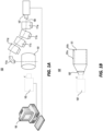
FIG. 1A is a schematic representation of a scintillating detector, according to an exemplary embodiment of the present invention. -
FIG. 1B is a schematic representation of another scintillating detector, according to an exemplary embodiment of the present invention. -
FIG. 2A is a schematic representation of a scintillating detector with an isocenter sensor, according to an exemplary embodiment of the present invention. -
FIG. 2B is a schematic representation of another scintillating detector with an isocenter sensor, according to an exemplary embodiment of the present invention. -
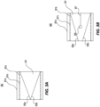
FIG. 3A is a schematic representation of a scintillating detector with reflective surfaces, according to an exemplary embodiment of the present invention. -
FIG. 3B is a schematic representation of a scintillating detector with reflective surfaces and an isocenter sensor, according to an exemplary embodiment of the present invention. -
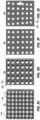
FIG. 3C is a schematic representation of an anti-scattering grid for use in a scintillating detector, according to an exemplary embodiment of the present invention. -
FIG. 3D is a schematic representation of a pixel mask for use in a scintillating detector, according to an exemplary embodiment of the present invention. -
FIG. 3E is a schematic representation of a distorted image of the pixel mask ofFIG. 3D . -
FIG. 3F is a schematic representation of a corrected image of the pixel mask ofFIG. 3D . -
FIG. 4 is a schematic illustration of entry and exit points of a radiation beam into a scintillating detector, according to an exemplary embodiment of the present invention. -
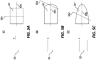
FIG. 5A is a schematic representation of a trunk-like scintillating detector, according to an exemplary embodiment of the present invention. -
FIG. 5B is a schematic representation of a trunk-like scintillating detector with an end cap, according to an exemplary embodiment of the present invention. -
FIG. 5C is a schematic representation of a scintillating detector with continuously decreasing cross-sectional area, according to an exemplary embodiment of the present invention. -
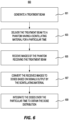
FIG. 6 is a flowchart of a method for determining a dose distribution of a radiation beam, according to an exemplary embodiment of the present invention. -
FIG. 7 is a schematic representation of coordinate systems for a scintillating detector and a camera, according to an exemplary embodiment of the present invention. - The disclosed embodiments relate to scintillating detectors and methods of use of the same. For example, embodiments of the present invention may be used to perform quality assurance on a radiation beam.
- According to an embodiment of the present invention, a detector system for evaluating radiation delivered by a radiation beam output from a beam generator may comprise a hollow phantom enclosing a volume or cavity and having an outer surface for exposure to radiation and an inner surface coated, at least in part, with a scintillating material. The hollow phantom may comprise any shape. For example, the hollow phantom may have translational symmetry along at least one axis. Accordingly, the hollow phantom may be cylindrical. Additionally or alternatively, the hollow phantom may not be rotationally symmetrical about the at least one axis. Accordingly, the hollow phantom may have an elliptical, rather than circular, base.
- In any of the embodiments above, the hollow phantom may further comprise an end cap. For example, the end cap may comprise a semi-spherical, semi-ellipsoid, or the like. Additionally or alternatively, the hollow phantom may have a cross-sectional area that decreases along at least one axis. For example, the hollow phantom may have a circular or elliptical cross-section with a radius or an axis that decreases along an axis of the hollow phantom.
- The inner surface may be coated, at least in part, with a scintillating material. For example, the scintillating material may comprise an inorganic or organic scintillator, such as anthracene, stilbene, naphthalene, a scintillating solution, or the like. Additionally or alternatively, the scintillating material may comprise a plastic scintillator having a fluor suspended in or bonded to a base comprising a polymeric matrix. Accordingly, when the radiation passes through the phantom, the scintillating material will transmit a signal, i.e., illuminate, due to the radiation. The scintillating surface may be uniformly coated or sub-divided into one or more smaller scintillating spots. Additionally with or alternatively to sub-division into scintillating spots, a pixel mask with narrow openings may provide a granular light emission from the phantom.
- Although described as "coated," the inner surface may comprise scintillating material in other ways. For example, a foil of scintillating material may be placed or otherwise attached (e.g., via adhesive or the like) to the phantom such that the foil comprises the inner surface. In such embodiments, the foil or other scintillating material placed on or otherwise attached to the phantom may be uniform or sub-divided into one or more smaller scintillating spots.
- The scintillating detector may further comprise a camera (e.g., comprising a lens system and converter to electrical signal, like a CCD or CMOS sensor) external to the enclosed volume and configured to view at least a portion of the inner surface through an opening of the hollow phantom. Accordingly, the camera may capture images of the illumination of the scintillating material caused by the radiation. In some embodiments, an accelerator used to generate the radiation may generate short pulses, e.g., having a period between 1 ms and 10 ms. Accordingly, the images may be synchronized with the pulses in order to increase the signal-to-noise ratio. The camera may capture such images sequentially during a particular treatment time. The camera may further include optical filters to limit the sensitivity to a wavelength band or to cut-off the lower or higher end of the wavelength spectrum. The camera (optionally with its lens) may be embedded in air, water or another transparent gas or liquid.
- The scintillating detector may further comprise at least one processor configured to receive images from the camera and calculate a representation of a dose of the radiation based on the received images. For example, the at least one processor may use one or more properties of the illumination radiation such as wavelength, brightness, shape, or the like, to determine properties of the beam, such as amplitude, wavelength, energy spread, or the like. These properties may be mapped onto known locations of the scintillating material to determine positional dose distributions of the radiation. For example, the known locations may be derived from a scan of the hollow phantom, e.g., a computed tomography (CT) scan.
- The at least one processor may adjust brightness of one or more first pixels corresponding with scintillating portions of the received images based on brightness of one or more second pixels corresponding with non-scintillating portions of the received images. For example, as explained above, the inner surface may be sub-divided into one or more smaller scintillating spots. Accordingly, the one or more scintillating spots may result in scintillating portions of the images captured by the camera while the non-scintillating spots (also called "dark" spots) may result in the non-scintillating portions (also called "dark" portions) of the images captured by the camera. Similarly, in embodiments where the foil or other scintillating material placed on or otherwise attached to the phantom is sub-divided into one or more smaller scintillating spots, the one or more scintillating spots may result in scintillating portions of the images captured by the camera while the non-scintillating spots (also called "dark" spots) may result in the non-scintillating portions (also called "dark" portions) of the images captured by the camera.
- Reference will now be made in detail to exemplary embodiments and aspects of the present invention, examples of which are illustrated in the accompanying drawings.
-
FIG. 1A is a schematic representation of ascintillating detector 100.Detector 100 may comprise ahollow phantom 101. As described above,hollow phantom 101 may be cylindrical. Alternatively,hollow phantom 101 may have an elliptical cross-section and/or may have a cross-sectional area that decreases along at least one axis.Detector 100 may further comprise acamera 103.Camera 103 is configured to view the inner surface ofphantom 101 through anopening facing camera 103. The opening may comprise an uncovered surface ofphantom 101 or may comprise a transparent material (whether solid or liquid, as discussed above) through whichcamera 103 may obtain images of the inner surface ofphantom 101. - As further depicted in
FIG. 1A ,detector 100 may comprise acomputer 105 or other processing device (such as a central processing unit (CPU), graphics processing unit (GPU), field-programmable gate array (FPGA),application specific integrated circuit (ASIC), or the like) to perform analysis on images captured bycamera 103. Although depicted as separate inFIG. 1A ,computer 105 may be integrated withcamera 103, e.g., by using one or more integrated circuits (ICs) ofcamera 103 to perform the analysis. - As further depicted in
FIG. 1 ,phantom 101 may receive aradiation beam 109 generated byradiation generator 107.Generator 107 may comprise a linear accelerator (LINAC) system or other system that generatesradiation beam 109. In addition, a delivery system may directradiation beam 109 tophantom 101. For example, as depicted inFIG. 1 , the delivery system may comprise a plurality of magnets, such as bendingmagnets magnet 111e. The magnets may comprise dipole magnets, quadrupole magnets, or any combination thereof. As known in the art, the linear accelerator may generate aradiation beam 109 for delivery to a patient for treatment or, as discussed more below, tophantom 101. The disclosed embodiments may be used with any known type of linear accelerator used to deliver a radiation beam for radiation therapy purposes, such as linear accelerators having a rotatable gantry, having a kilovoltage (KV) imaging system, or a megavoltage (MV) imaging system. -
Computer 105 may perform image analysis functions on images fromcamera 103 in order to calculate a representation of a dose of a radiation delivered tophantom 101. The representations may be spatial, temporal, or integrated, at least in part, over space and/or time.Computer 105 may further compare the calculated dose representation to a predicted dose representation. Deviations from the predicted dose representation may be used to adjust the accelerator or radiation source used for treatment, and/or to adjust one or more lenses or other focusing instruments used to direct the radiation tophantom 101. Alternatively,computer 105 may use a predicted dose to derive an expected measurement (e.g., an expected light intensity) fromcamera 103.Computer 105 may then compare the expected measurement to the actual measurement, and to then perform adjustments accordingly, as explained above.Computer 105 may, for example, be part of a conventional treatment planning system used, as known in the art, to generate a radiation treatment plan and control a linear accelerator system in order to deliver a radiation beam for treating a patient in accordance with the generated radiation treatment plan. -
FIG. 1B is a schematic representation of another scintillating detector 100'. Detector 100' may comprise ahollow phantom 101 as depicted inFIG. 1A . As depicted inFIG. 1B ,phantom 101 may comprise anouter surface 101a for receiving radiation. For example,outer surface 101a may comprise a plastic shell. As further depicted inFIG. 1B ,phantom 101 may comprise aninner surface 101b made of a scintillating material. Although not depicted inFIG. 1A ,outer surface 101a andinner surface 101b are also present inphantom 101 ofFIG. 1A . - As used herein, the term "surface" refers to a three-dimensional surface having depth (e.g., a layered surface) and not merely to the two-dimensional surface area of an object. For example, the
outer surface 101a may comprise a plurality of plastic layers bonded together to form the plastic shell that encloses a cavity or space. In another example,inner surface 101b may comprise a supporting plastic as well as the scintillating material (or a plurality of scintillating layers) bonded together. As explained above, the scintillating material may be arranged as a uniform layer or may be sub-divided into pixels or other smaller regions optically isolated from each other.Surface 101a is referred to as an "outer" surface because it is provided on top of an "inner" surface (surface 101b). In other words, the terms "inner" and "outer" are used to relate the surfaces relative to each other rather than relative to any absolute measure. - As further depicted in
FIG. 1B , camera 103' may be integrally formed withphantom 101. For example, one or more supports may connect camera 103' tophantom 101. Moreover, camera 103' may be focused by one or more lenses, e.g., lens 105', installed between camera 103' andphantom 101. Although not depicted inFIG. 1B ,computer 105 ofFIG. 1A is also included in detector 100'. -
FIG. 2A is a schematic representation of ascintillating detector 200.Detector 200 may comprise ahollow phantom 201.Hollow phantom 201 may be similar tohollow phantom 101 ofFIGS. 1A and 1B . In addition,camera 203 andcomputer 205 may be similar tocamera 103 ofFIG. 1A (or camera 103' ofFIG. 1B ) andcomputer 105 ofFIGS. 1A and 1B , respectively. - As depicted in
FIG. 2A ,phantom 201 may further comprise anisocenter sensor 203. For example,isocenter sensor 203 may comprise any type of sensor, such as an ionization chamber, luminescent sensor, or the like. Alternatively, theisocenter sensor 203 may comprise a small body having an internal cavity visible tocamera 203 and coated with the same scintillating material used on the inner surface ofphantom 201. Accordingly,isocenter sensor 203 may produce measurements dependent on the relationship between the thickness of the scintillating material and the radiation strength rather than on the details of the sensor surface. - As further depicted in
FIG. 2A ,isocenter sensor 203 may be centered on one or more axes ofphantom 201. For example,isocenter sensor 203 is centered onaxis 205b, around whichphantom 201 has translational symmetry. In addition,isocenter sensor 203 is centered onaxis 205b, which may represent an axis of the radiation. -
FIG. 2B is a schematic representation of another scintillating detector 200'. Detector 200' may comprise ahollow phantom 201 and acamera 203, as depicted inFIG. 2A . Although not depicted inFIG. 2B ,computer 205 ofFIG. 2A is also included in detector 200'. - As depicted in
FIG. 2B ,phantom 201 may comprise anouter surface 201a for receiving radiation. For example,outer surface 201a may comprise a plastic shell. As further depicted inFIG. 2B ,phantom 201 may comprise aninner surface 201b made of a scintillating material. Although not depicted inFIG. 2A ,outer surface 201a andinner surface 201b are also present inphantom 201 ofFIG. 2A . - As further depicted in
FIG. 2B ,phantom 201 may further comprise anisocenter sensor 203 as depicted inFIG. 2A .Isocenter sensor 203 may be held inplace using holder 207.Holder 207 may connect to any portion ofinner surface 201b. To avoid interfering withcamera 203,holder 207 may connect to a portion ofinner surface 201b further fromcamera 203 thanisocenter sensor 203. Although not depicted inFIG. 2A ,holder 207 may also present inphantom 201 ofFIG. 2A . -
FIG. 3A is a schematic representation of ahollow phantom 300, which may be used in a scintillating detector of the present invention.Hollow phantom 300 may be similar tohollow phantom 101 ofFIGS. 1A and 1B . - As depicted in
FIG. 3A ,phantom 300 may enclose avolume 301 and may comprise anouter surface 301a for receiving radiation. For example,outer surface 301a may comprise a plastic shell. As further depicted inFIG. 3A ,phantom 300 may comprise aninner surface 301b made of a scintillating material.Phantom 300 may also include one or more opticalanti-scattering grids 301c to preventreflectors phantom 300. - As further depicted in
FIG. 3A ,phantom 300 may include one or more reflective surfaces, e.g.,reflectors Reflectors inner surface 301b toward the camera (not shown). This may allow for the entire image of the camera to include information about the radiation rather than only a portion of the image. In such an embodiment, the computer (not shown) may have to perform post-processing on the received images to correct for distortions in the image caused byreflectors reflectors -
FIG. 3B is a schematic representation of a phantom 300', which may be used in a scintillating detector of the present invention. Phantom 300' may enclose avolume 301 as depicted inFIG. 3A . - Similar to
FIG. 3A , phantom 300' may comprise anouter surface 301a for receiving radiation. For example,outer surface 301a may comprise a plastic shell. In addition, phantom 300' may comprise aninner surface 301b made of a scintillating material. Phantom 300' may also include one or moreanti-scattering grids 301c to preventreflectors - Similar to
FIG. 3A , phantom 300' may include one or more reflective surfaces, e.g.,reflectors Reflectors inner surface 301b toward the camera (not shown). As further depicted inFIG. 3B , phantom 300' may include anisocenter sensor 305 similar tosensor 203 depicted inFIGS. 2A and 2B . In addition,isocenter sensor 305 may be held in place byholder 307 similar toholder 207 depicted inFIG. 2A . - In any of the embodiments depicted in
FIGS. 1A, 1B ,2A, 2B ,3A, or 3B , the hollow phantom may further include an anti-glare filter (oranti-scatter grid 301c, as described with respect toFIG. 3A ) on the inner surface of the scintillator grid. This filter (or grid) may ensure that light rays leave the scintillator only in the normal direction or the direction which leads to a direct image on the camera sensor. This may reduce glare present in the received images, resulting in both improved spatial resolution and reducing post-processing needs. - In any of the embodiments depicted in
FIGS. 1A, 1B ,2A, 2B ,3A, or 3B , the hollow phantom may be filled with a solid or liquid that is transparent to the signal emitted by the scintillating material. Accordingly, inFIGS. 3A and 3B ,reflectors isocenter sensor 305 or at least a middle portion of the phantom. For example,reflectors - Moreover, in such embodiments, Cherenkov radiation may be emitted in the backscatter medium (that is, the solid or liquid filling the phantom). This may be, for example, concentrated in the blue spectral range. Accordingly, in such embodiments, the scintillator material may be selected to emit at a different wavelength (e.g., red) and/or using a filter (e.g., an edge or a band-pass filter) in front of the camera (not shown) in order to discriminate the signal from the Cherenkov radiation. Such a discrimination might be performed as well by using a processing of information from color channels of the camera. In an example not forming part of the presently claimed invention, the scintillator may be replaced by a thick (e.g., 2cm) layer of translucent material with a high refractive index (e.g., 1.5) or water, using Cerenkov radiation instead of scintillation light for the radiation detection.
-
FIG. 3C is a schematic representation of ananti-scattering grid 310 for use in a scintillating detector. For example,anti-scattering grid 310 may be used asanti-scattering grid 301c ofFIGS. 3A and 3B . As depicted inFIG. 3C ,grid 310 may comprise alternatingstrips -
FIG. 3D is a schematic representation of apixel mask 320 for use in a scintillating detector. For example,pixel mask 320 may be used in addition to or in lieu ofanti-scattering grid 301c ofFIGS. 3A and 3B .Pixel mask 320 may be formed of a bulk material or may comprise a thin non-transparent sheet with one or more openings, e.g., opening 321a and 321b. Although depicted as elliptical, the openings may be any geometric shape, such as square, circular, hexagonal, or the like. Although depicted as of uniform shape, the openings may comprise different shapes. The mask may comprise a material having similar reflective properties as the scintillating layer, such that the light reflected at non-transparent parts of the mask may be representative for the reflection of scattered light in open parts of the mask. Accordingly, the light reflected at one or more of the non-transparent parts may be used for optical backscatter correction in post-processing. The mask, whether arranged as a regular pattern or in any other geometric configuration (or an arrangement of individual scintillating pixels, whether arranged as a regular pattern or in any other geometric configuration) may be used to determine the position of one or more elements of the scintillating surface on a resulting camera image. Thus, the mask or other arrangement of scintillating pixels may be used for the localization of points on the surface of the phantom and/or for distortion correction of a calculated dosimetric image. -
FIG. 3E is a schematic representation of adistorted image 330 of thepixel mask 320 ofFIG. 3D . For example, as shown inFIG. 3E a charge-coupled device (CCD) camera may distort the pattern in which the openings (such as openings 331a and 331b) are arranged. Accordingly, at least one processor (e.g., of a computer processing images from the camera) may correct distortedimage 330 to corrected image 349 (shown inFIG. 3F ) based on the known arrangement of the openings inpixel mask 320. -
FIG. 4 is an example of aradiation beam 403 passing through a hollow phantom. Similar toFIGS. 1B ,2B ,3A, and 3B , the hollow phantom comprises anouter surface 401a for receiving radiation frombeam 403 and aninner surface 401b made of a scintillating material. Although not depicted inFIG. 4 , the hollow phantom may further include one or more reflectors, an isocenter sensor, and/or an anti-scattering grid or anti-glare filter, as described above. - As depicted in
FIG. 4 ,beam 403 intersectsinner surface 401b atlocations FIG. 4 , the signal frominner surface 401b will appear nearlocations beam 403 may be determined using captured images, optionally mapped to information about the shape, density, and locations ofinner surface 401b and, in embodiments with reflectors, of the reflectors. -
FIG. 5A is an example of ascintillating detector 500 having asymmetrical phantom 501. As depicted inFIG. 5A ,phantom 501 has translational symmetry alongaxis 505b. Accordingly,axis 505a may represent a possible axis of entry for a beam. -
FIG. 5B is an example of a scintillating detector 500' having a phantom 501' with an end cap. As depicted inFIG. 5B , phantom 501' is not symmetrical alongaxis 505b because of the end cap, which may be semi-spherical, semi-ellipsoid, or the like. Accordingly,axis 505a' may represent a possible axis of entry for a beam to phantom 501', an axis of entry not usable withphantom 501 ofFIG. 5A . -
FIG. 5C is an example of ascintillating detector 500" having aphantom 501". As depicted inFIG. 5C ,phantom 501" is not symmetrical alongaxis 505b because it has a decreasing cross-sectional area alongaxis 505b. The decrease may be continuous, as depicted inFIG. 5C , or may be partially discontinuous, e.g., having one or more lengths of constant or increasing cross-sectional area alongaxis 505b. Accordingly, axis 505a" may represent a possible axis of entry for a beam tophantom 501", an axis of entry not usable withphantom 501 ofFIG. 5A or phantom 501' ofFIG. 5B . - In all of
FIGS. 5A, 5B, and 5C ,camera 503 is configured to view an inner surface of the phantom. Although not depicted,computer 105 ofFIG. 1A and/orcomputer 205 ofFIG. 2A is also included in any ofdetectors -
FIG. 6 depictsmethod 600 for determining a dose distribution of a radiation beam.Method 600 may be performed by, for example,computer 105 ofFIG. 1A ,computer 205 ofFIG. 2A , or any other general-purpose or special-purpose computing device. - At
step 601, theprocessing device - At
step 603, theprocessing device phantom 101,phantom 201,phantom 301,phantom 501, phantom 501', orphantom 501") having a scintillating material for a particular time. For example, theprocessing device phantom 101,phantom 201,phantom 301,phantom 501, phantom 501', orphantom 501") or otherwise consistent with the present invention. - At
step 605, theprocessing device processing device camera 103 viewing the scintillating material of the phantom. Accordingly, the images may include one or more bright spots caused by a signal released from the scintillating material caused by the radiation beam. For example, the bright spots may represent the entry and exit points of the beam into the phantom. - The received images may comprise camera frames captured during the time of the radiation. The received images may also include frames captured before the radiation and/or after the radiation. In embodiments where the frames are monochromatic, the
processing device processing device - In embodiments where the frames are in color, the
processing device processing device - At
step 607, theprocessing device processing device - The
processing device Fig. 7 . As depicted inFig. 7 , (x,y) may indicate the two-dimensional frame of pixels of the camera and, accordingly, of the received images. As also depicted inFig. 7 , (x',y',z') may indicate the three-dimensional frame onto which, for example, the received images may be projected. As further shown, (α,β) may indicate the two-dimensional frame of the hollow phantom. - In some embodiments, to convert the images to representations of doses, the
processing device camera 103, and/or dependence of intensity on parameters, such as beam quality, gain of the measurement chain, or the like. Theprocessing device - Before or after conversion to representations of doses, the
processing device - The
processing device camera 103 to the two-dimensional phantom surface. Accordingly, theprocessing device 
camera 103, and d(α,β,t), which is the dose representation in the two-dimensional coordinate system (α,β) of the phantom surface. Alternatively, theprocessing device processing device 
camera 103, and g(α,β,t), which is the intensities in the two-dimensional coordinate system (α,β) of the phantom surface. - At
step 609, theprocessing device processing device camera 103. Theprocessing device -
Steps processing device processing device -
Method 600 may further include additional steps. For example,method 600 may further include controlling a scanner to perform a scan of the phantom (e.g.,phantom 101,phantom 201,phantom 301,phantom 501, phantom 501', orphantom 501") having the scintillating material. Accordingly, theprocessing device processing device - Accordingly,
method 600 may include determining positional dose distributions based on the dose distribution and the scan of the phantom. In some embodiments, theprocessing device processing device - In any of the embodiments described above,
method 600 may further include comparing the dose distribution to a predicted dose distribution. For example, theprocessing device 
processing device 
- Alternatively,
method 600 may compare measured intensities to predicted intensities based on a predicted dose distribution. For example, alternatively tosteps processing device - In one implementation of such an alternative embodiments, the
processing device processing device - The
processing device processing device processing device - Time-resolved comparisons of G(x,y,t') and g(x,y,t) may include 3D methods, e.g., a 3D gamma analysis. Alternatively, time-resolved comparisons of G(x,y, t') and g(x,y, t) may include 2D methods (such as 2D gamma) based on interpolation of G(x,y, t') and/or g(x,y, t) across a common time axis such that the two functions may be compared directly at any time (e.g., G(x,y, t') may be interpolated such that time t' aligns with time t or g(x,y,t) may be interpolated such that time t aligns with time t').
- Alternatively, as explained above, the
processing device processing device - In any of the embodiments described above,
method 600 may further include applying one or more corrections based on the comparison(s). For example, theprocessing device processing device step 603, described above. - The foregoing description has been presented for purposes of illustration. It is not exhaustive and is not limited to precise forms or embodiments disclosed. Modifications and adaptations of the embodiments will be apparent from consideration of the specification and practice of the disclosed embodiments. For example, the described implementations include hardware and software, but systems and methods consistent with the present invention can be implemented with hardware alone. In addition, while certain components have been described as being coupled to one another, such components may be integrated with one another or distributed in any suitable fashion.
- Moreover, while illustrative embodiments have been described herein, the scope includes any and all embodiments falling within the scope as defined by the appended claims.
Claims (15)
- A detector system for evaluating radiation delivered by a radiation beam (109) output from a beam generator (107), comprising:a hollow phantom (101) enclosing an internal volume and havingan outer surface (101a), extending around the internal volume, for exposure to radiation, andan inner surface (101b) comprising, at least in part, a scintillating material and facing the internal volume; anda camera (103) external to the enclosed volume and configured to view at least a portion of the inner surface (101b), through an opening of the hollow phantom (101), when radiated by the radiation beam (109);characterized by further comprising at least one processor (105) configured to:receive images from the camera (103);adjust the brightness of one or more first pixels corresponding with scintillating portions of the received images based on brightness of one or more second pixels corresponding with non-scintillating portions of the received images; andcalculate, based on the adjusted images, a spatial dose distribution produced by the radiation delivered by the radiation beam (109) to the hollow phantom (101).
- The system of claim 1, wherein the phantom (101) is translationally symmetric along at least one axis.
- The system of claim 2, wherein the phantom (101) is cylindrical.
- The system of claim 2, wherein the phantom (101) is not rotationally symmetric about the at least one axis.
- The system of claim 4, wherein the phantom (101) has an elliptical cross-section.
- The system of claim 1, wherein the phantom (101) has a conical shape.
- The system of claim 1, wherein the phantom (101) is made of plastic.
- The system of claim 1, wherein the volume is filled with a light transparent material.
- The system of claim 1, further comprising:one or more point sensors placed along an axis of the volume,wherein the point sensor is held in place by a holder connected to a wall of the phantom (101).
- The system of claim 9, wherein the point sensor is made out of the scintillating material and is placed in a field of view of the camera (103).
- The system of claim 1, further comprising:one or more reflective surfaces (303a,303b) placed between the scintillating material and an axis of the phantom.
- A method of determining a dose distribution of a radiation beam, comprising:controlling (601) a radiation generator (107) to generate the radiation beam (109);controlling (603) a delivery system to deliver the radiation beam (109) to a hollow phantom (101) with an outer surface (101a), extending around an internal volume of the phantom, for exposure to radiation, and an inner surface (101b) comprising, at least in part, a scintillating material and facing the internal volume; andreceiving (605) images of the hollow phantom (101) receiving the radiation beam (109);characterized by further comprising:adjusting the brightness of one or more first pixels corresponding with scintillating portions of the received images based on brightness of one or more second pixels corresponding with non-scintillating portions of the received images; andcalculating, based on the adjusted images, a spatial dose distribution produced by the radiation delivered by the radiation beam (109) to the hollow phantom (101).
- The method of claim 12, further comprising:applying one or more corrections to the measured images; andcomparing the dose distribution to a predicted dose distribution.
- The method of claim 13, wherein the one or more corrections include at least one of a correction for the incident energy, a correction for the energy distribution, and a correction for the angle of incidence.
- The method of any of claims 12-14, further comprising:controlling a scanner to perform a scan of the phantom (101); anddetermining positional dose distributions based on the calculated dose distribution and the scan of the phantom (101).
Applications Claiming Priority (2)
| Application Number | Priority Date | Filing Date | Title |
|---|---|---|---|
| US201862701890P | 2018-07-23 | 2018-07-23 | |
| PCT/EP2019/069709 WO2020020840A1 (en) | 2018-07-23 | 2019-07-22 | Scintillating detectors for quality assurance of a therapy photon beam |
Publications (2)
| Publication Number | Publication Date |
|---|---|
| EP3827287A1 EP3827287A1 (en) | 2021-06-02 |
| EP3827287B1 true EP3827287B1 (en) | 2023-03-22 |
Family
ID=67439206
Family Applications (1)
| Application Number | Title | Priority Date | Filing Date |
|---|---|---|---|
| EP19744666.9A Active EP3827287B1 (en) | 2018-07-23 | 2019-07-22 | Scintillating detectors for quality assurance of a therapy photon beam |
Country Status (3)
| Country | Link |
|---|---|
| US (1) | US11402523B2 (en) |
| EP (1) | EP3827287B1 (en) |
| WO (1) | WO2020020840A1 (en) |
Families Citing this family (5)
| Publication number | Priority date | Publication date | Assignee | Title |
|---|---|---|---|---|
| US20230293132A1 (en) * | 2016-10-25 | 2023-09-21 | Shanghai United Imaging Healthcare Co., Ltd. | Systems and methods for image acquisition |
| US10569105B2 (en) * | 2017-05-26 | 2020-02-25 | Accuray Incorporated | Radiation based treatment beam position calibration and verification |
| WO2022187743A1 (en) * | 2021-03-05 | 2022-09-09 | The Trustees Of Dartmouth College | Cherenkov imaging-based solution for mr-linac quality assurance |
| JP7489667B2 (en) * | 2021-03-30 | 2024-05-24 | 株式会社日立製作所 | Treatment planning apparatus, treatment plan generation method and computer program |
| PL446944A1 (en) | 2023-11-30 | 2025-06-02 | Politechnika Krakowska im. Tadeusza Kościuszki | Phantom device for teleradiotherapy for determining the spatial distribution of ionizing radiation dose |
Family Cites Families (6)
| Publication number | Priority date | Publication date | Assignee | Title |
|---|---|---|---|---|
| US7157696B2 (en) * | 2002-04-04 | 2007-01-02 | Synarc, Inc. | Test object for calibration of imaging measurements of mammalian skeletal joints |
| JP5918865B2 (en) * | 2012-12-26 | 2016-05-18 | 三菱電機株式会社 | Dose distribution measuring device |
| CA2908092A1 (en) * | 2013-03-28 | 2014-10-02 | Atomic Energy Of Canada Limited / Energie Atomique Du Canada Limitee | System and method for real-time three-dimensional dosimetry |
| US10067238B2 (en) * | 2013-08-13 | 2018-09-04 | Brett Nelson | Method and apparatus for ion beam Bragg Peak measurement |
| US9604077B2 (en) * | 2014-06-16 | 2017-03-28 | The Board Of Trustees Of The Leland Stanford Junior University | Visualizing radiation therapy beam in real-time in the context of patient's anatomy |
| US10569105B2 (en) * | 2017-05-26 | 2020-02-25 | Accuray Incorporated | Radiation based treatment beam position calibration and verification |
-
2019
- 2019-07-22 WO PCT/EP2019/069709 patent/WO2020020840A1/en not_active Ceased
- 2019-07-22 EP EP19744666.9A patent/EP3827287B1/en active Active
- 2019-07-22 US US17/262,066 patent/US11402523B2/en active Active
Also Published As
| Publication number | Publication date |
|---|---|
| WO2020020840A1 (en) | 2020-01-30 |
| US11402523B2 (en) | 2022-08-02 |
| US20210311212A1 (en) | 2021-10-07 |
| EP3827287A1 (en) | 2021-06-02 |
Similar Documents
| Publication | Publication Date | Title |
|---|---|---|
| US11402523B2 (en) | Scintillating detectors for quality assurance of a therapy photon beam | |
| US11000703B2 (en) | Imaging system and methods of high resolution Cherenkov dose images utilizing radio-optical triggering | |
| US11813482B2 (en) | Advanced cherenkov-based imaging systems, tools, and methods of feedback control, temporal control sequence image capture, and quantification in high resolution dose images | |
| US7636419B1 (en) | Method and apparatus for automated three dimensional dosimetry | |
| US11633627B2 (en) | Dosimetry systems for radiation treatment using radiation-detector-triggered cameras to image Cherenkov emissions or thin-sheet scintillators | |
| CN104870054B (en) | Dosage distribution measurement device | |
| Alexander et al. | Assessment of imaging Cherenkov and scintillation signals in head and neck radiotherapy | |
| US20170252579A1 (en) | Linear accelerator with cerenkov emission detector | |
| JP7219297B2 (en) | Ambient light suppression using color space information to derive per-pixel attenuation factors | |
| Black et al. | An investigation of clinical treatment field delivery verification using cherenkov imaging: IMRT positioning shifts and field matching | |
| US20240108916A1 (en) | Quality Assurance Device for a Medical Accelerator | |
| Darne et al. | A novel proton-integrating radiography system design using a monolithic scintillator detector: Experimental studies | |
| US10067238B2 (en) | Method and apparatus for ion beam Bragg Peak measurement | |
| EP1857836A1 (en) | Device and method for discriminating cerenkov and scintillation radiation | |
| Alexander et al. | Detective quantum efficiency of intensified CMOS cameras for Cherenkov imaging in radiotherapy | |
| Guillot et al. | Performance assessment of a 2D array of plastic scintillation detectors for IMRT quality assurance | |
| US11975219B2 (en) | Systems and methods for particle portal imaging | |
| WO2014189260A1 (en) | Device for measuring radiation dose capable of horizontal and rotational operation and device for detecting radiation thereof | |
| CN117599355A (en) | A rapid quality control system and method for radiotherapy | |
| JP2020081874A (en) | Determination of radiation dose measurement | |
| KR102209585B1 (en) | System and method for measuring three-dimensional dose distribution | |
| CN109211943A (en) | Light emission open country coherence measurement system, method, radiating system and imaging detector | |
| Monti et al. | Dosimetric verification of 6 and 18 MV intensity modulated photon beams using a dedicated fluoroscopic electronic portal imaging device (EPID) | |
| Altaf et al. | Quality assurance of intensity-modulated radiotherapy treatment planning: a dosimetric comparison | |
| Zhang | Cherenkov imaging and biochemical sensing in vivo during radiation therapy |
Legal Events
| Date | Code | Title | Description |
|---|---|---|---|
| STAA | Information on the status of an ep patent application or granted ep patent |
Free format text: STATUS: UNKNOWN |
|
| STAA | Information on the status of an ep patent application or granted ep patent |
Free format text: STATUS: THE INTERNATIONAL PUBLICATION HAS BEEN MADE |
|
| PUAI | Public reference made under article 153(3) epc to a published international application that has entered the european phase |
Free format text: ORIGINAL CODE: 0009012 |
|
| STAA | Information on the status of an ep patent application or granted ep patent |
Free format text: STATUS: REQUEST FOR EXAMINATION WAS MADE |
|
| 17P | Request for examination filed |
Effective date: 20210119 |
|
| AK | Designated contracting states |
Kind code of ref document: A1 Designated state(s): AL AT BE BG CH CY CZ DE DK EE ES FI FR GB GR HR HU IE IS IT LI LT LU LV MC MK MT NL NO PL PT RO RS SE SI SK SM TR |
|
| DAV | Request for validation of the european patent (deleted) | ||
| DAX | Request for extension of the european patent (deleted) | ||
| GRAP | Despatch of communication of intention to grant a patent |
Free format text: ORIGINAL CODE: EPIDOSNIGR1 |
|
| STAA | Information on the status of an ep patent application or granted ep patent |
Free format text: STATUS: GRANT OF PATENT IS INTENDED |
|
| INTG | Intention to grant announced |
Effective date: 20221123 |
|
| GRAS | Grant fee paid |
Free format text: ORIGINAL CODE: EPIDOSNIGR3 |
|
| GRAA | (expected) grant |
Free format text: ORIGINAL CODE: 0009210 |
|
| STAA | Information on the status of an ep patent application or granted ep patent |
Free format text: STATUS: THE PATENT HAS BEEN GRANTED |
|
| AK | Designated contracting states |
Kind code of ref document: B1 Designated state(s): AL AT BE BG CH CY CZ DE DK EE ES FI FR GB GR HR HU IE IS IT LI LT LU LV MC MK MT NL NO PL PT RO RS SE SI SK SM TR |
|
| REG | Reference to a national code |
Ref country code: GB Ref legal event code: FG4D |
|
| REG | Reference to a national code |
Ref country code: CH Ref legal event code: EP |
|
| REG | Reference to a national code |
Ref country code: IE Ref legal event code: FG4D |
|
| REG | Reference to a national code |
Ref country code: DE Ref legal event code: R096 Ref document number: 602019026677 Country of ref document: DE |
|
| REG | Reference to a national code |
Ref country code: AT Ref legal event code: REF Ref document number: 1555652 Country of ref document: AT Kind code of ref document: T Effective date: 20230415 |
|
| REG | Reference to a national code |
Ref country code: SE Ref legal event code: TRGR |
|
| P01 | Opt-out of the competence of the unified patent court (upc) registered |
Effective date: 20230522 |
|
| REG | Reference to a national code |
Ref country code: LT Ref legal event code: MG9D |
|
| REG | Reference to a national code |
Ref country code: NL Ref legal event code: MP Effective date: 20230322 |
|
| PG25 | Lapsed in a contracting state [announced via postgrant information from national office to epo] |
Ref country code: RS Free format text: LAPSE BECAUSE OF FAILURE TO SUBMIT A TRANSLATION OF THE DESCRIPTION OR TO PAY THE FEE WITHIN THE PRESCRIBED TIME-LIMIT Effective date: 20230322 Ref country code: NO Free format text: LAPSE BECAUSE OF FAILURE TO SUBMIT A TRANSLATION OF THE DESCRIPTION OR TO PAY THE FEE WITHIN THE PRESCRIBED TIME-LIMIT Effective date: 20230622 Ref country code: LV Free format text: LAPSE BECAUSE OF FAILURE TO SUBMIT A TRANSLATION OF THE DESCRIPTION OR TO PAY THE FEE WITHIN THE PRESCRIBED TIME-LIMIT Effective date: 20230322 Ref country code: LT Free format text: LAPSE BECAUSE OF FAILURE TO SUBMIT A TRANSLATION OF THE DESCRIPTION OR TO PAY THE FEE WITHIN THE PRESCRIBED TIME-LIMIT Effective date: 20230322 Ref country code: HR Free format text: LAPSE BECAUSE OF FAILURE TO SUBMIT A TRANSLATION OF THE DESCRIPTION OR TO PAY THE FEE WITHIN THE PRESCRIBED TIME-LIMIT Effective date: 20230322 |
|
| REG | Reference to a national code |
Ref country code: AT Ref legal event code: MK05 Ref document number: 1555652 Country of ref document: AT Kind code of ref document: T Effective date: 20230322 |
|
| PG25 | Lapsed in a contracting state [announced via postgrant information from national office to epo] |
Ref country code: NL Free format text: LAPSE BECAUSE OF FAILURE TO SUBMIT A TRANSLATION OF THE DESCRIPTION OR TO PAY THE FEE WITHIN THE PRESCRIBED TIME-LIMIT Effective date: 20230322 Ref country code: GR Free format text: LAPSE BECAUSE OF FAILURE TO SUBMIT A TRANSLATION OF THE DESCRIPTION OR TO PAY THE FEE WITHIN THE PRESCRIBED TIME-LIMIT Effective date: 20230623 Ref country code: FI Free format text: LAPSE BECAUSE OF FAILURE TO SUBMIT A TRANSLATION OF THE DESCRIPTION OR TO PAY THE FEE WITHIN THE PRESCRIBED TIME-LIMIT Effective date: 20230322 |
|
| PG25 | Lapsed in a contracting state [announced via postgrant information from national office to epo] |
Ref country code: SM Free format text: LAPSE BECAUSE OF FAILURE TO SUBMIT A TRANSLATION OF THE DESCRIPTION OR TO PAY THE FEE WITHIN THE PRESCRIBED TIME-LIMIT Effective date: 20230322 Ref country code: RO Free format text: LAPSE BECAUSE OF FAILURE TO SUBMIT A TRANSLATION OF THE DESCRIPTION OR TO PAY THE FEE WITHIN THE PRESCRIBED TIME-LIMIT Effective date: 20230322 Ref country code: PT Free format text: LAPSE BECAUSE OF FAILURE TO SUBMIT A TRANSLATION OF THE DESCRIPTION OR TO PAY THE FEE WITHIN THE PRESCRIBED TIME-LIMIT Effective date: 20230724 Ref country code: ES Free format text: LAPSE BECAUSE OF FAILURE TO SUBMIT A TRANSLATION OF THE DESCRIPTION OR TO PAY THE FEE WITHIN THE PRESCRIBED TIME-LIMIT Effective date: 20230322 Ref country code: EE Free format text: LAPSE BECAUSE OF FAILURE TO SUBMIT A TRANSLATION OF THE DESCRIPTION OR TO PAY THE FEE WITHIN THE PRESCRIBED TIME-LIMIT Effective date: 20230322 Ref country code: AT Free format text: LAPSE BECAUSE OF FAILURE TO SUBMIT A TRANSLATION OF THE DESCRIPTION OR TO PAY THE FEE WITHIN THE PRESCRIBED TIME-LIMIT Effective date: 20230322 |
|
| PG25 | Lapsed in a contracting state [announced via postgrant information from national office to epo] |
Ref country code: SK Free format text: LAPSE BECAUSE OF FAILURE TO SUBMIT A TRANSLATION OF THE DESCRIPTION OR TO PAY THE FEE WITHIN THE PRESCRIBED TIME-LIMIT Effective date: 20230322 Ref country code: PL Free format text: LAPSE BECAUSE OF FAILURE TO SUBMIT A TRANSLATION OF THE DESCRIPTION OR TO PAY THE FEE WITHIN THE PRESCRIBED TIME-LIMIT Effective date: 20230322 Ref country code: IS Free format text: LAPSE BECAUSE OF FAILURE TO SUBMIT A TRANSLATION OF THE DESCRIPTION OR TO PAY THE FEE WITHIN THE PRESCRIBED TIME-LIMIT Effective date: 20230722 |
|
| REG | Reference to a national code |
Ref country code: DE Ref legal event code: R097 Ref document number: 602019026677 Country of ref document: DE |
|
| PLBE | No opposition filed within time limit |
Free format text: ORIGINAL CODE: 0009261 |
|
| STAA | Information on the status of an ep patent application or granted ep patent |
Free format text: STATUS: NO OPPOSITION FILED WITHIN TIME LIMIT |
|
| PG25 | Lapsed in a contracting state [announced via postgrant information from national office to epo] |
Ref country code: SI Free format text: LAPSE BECAUSE OF FAILURE TO SUBMIT A TRANSLATION OF THE DESCRIPTION OR TO PAY THE FEE WITHIN THE PRESCRIBED TIME-LIMIT Effective date: 20230322 Ref country code: DK Free format text: LAPSE BECAUSE OF FAILURE TO SUBMIT A TRANSLATION OF THE DESCRIPTION OR TO PAY THE FEE WITHIN THE PRESCRIBED TIME-LIMIT Effective date: 20230322 Ref country code: CZ Free format text: LAPSE BECAUSE OF FAILURE TO SUBMIT A TRANSLATION OF THE DESCRIPTION OR TO PAY THE FEE WITHIN THE PRESCRIBED TIME-LIMIT Effective date: 20230322 |
|
| 26N | No opposition filed |
Effective date: 20240102 |
|
| PG25 | Lapsed in a contracting state [announced via postgrant information from national office to epo] |
Ref country code: MC Free format text: LAPSE BECAUSE OF FAILURE TO SUBMIT A TRANSLATION OF THE DESCRIPTION OR TO PAY THE FEE WITHIN THE PRESCRIBED TIME-LIMIT Effective date: 20230322 |
|
| PG25 | Lapsed in a contracting state [announced via postgrant information from national office to epo] |
Ref country code: MC Free format text: LAPSE BECAUSE OF FAILURE TO SUBMIT A TRANSLATION OF THE DESCRIPTION OR TO PAY THE FEE WITHIN THE PRESCRIBED TIME-LIMIT Effective date: 20230322 |
|
| REG | Reference to a national code |
Ref country code: CH Ref legal event code: PL |
|
| PG25 | Lapsed in a contracting state [announced via postgrant information from national office to epo] |
Ref country code: LU Free format text: LAPSE BECAUSE OF NON-PAYMENT OF DUE FEES Effective date: 20230722 |
|
| PG25 | Lapsed in a contracting state [announced via postgrant information from national office to epo] |
Ref country code: LU Free format text: LAPSE BECAUSE OF NON-PAYMENT OF DUE FEES Effective date: 20230722 |
|
| REG | Reference to a national code |
Ref country code: IE Ref legal event code: MM4A |
|
| PG25 | Lapsed in a contracting state [announced via postgrant information from national office to epo] |
Ref country code: CH Free format text: LAPSE BECAUSE OF NON-PAYMENT OF DUE FEES Effective date: 20230731 |
|
| PG25 | Lapsed in a contracting state [announced via postgrant information from national office to epo] |
Ref country code: IT Free format text: LAPSE BECAUSE OF FAILURE TO SUBMIT A TRANSLATION OF THE DESCRIPTION OR TO PAY THE FEE WITHIN THE PRESCRIBED TIME-LIMIT Effective date: 20230322 |
|
| PG25 | Lapsed in a contracting state [announced via postgrant information from national office to epo] |
Ref country code: IE Free format text: LAPSE BECAUSE OF NON-PAYMENT OF DUE FEES Effective date: 20230722 |
|
| PG25 | Lapsed in a contracting state [announced via postgrant information from national office to epo] |
Ref country code: IE Free format text: LAPSE BECAUSE OF NON-PAYMENT OF DUE FEES Effective date: 20230722 |
|
| PG25 | Lapsed in a contracting state [announced via postgrant information from national office to epo] |
Ref country code: BG Free format text: LAPSE BECAUSE OF FAILURE TO SUBMIT A TRANSLATION OF THE DESCRIPTION OR TO PAY THE FEE WITHIN THE PRESCRIBED TIME-LIMIT Effective date: 20230322 |
|
| PG25 | Lapsed in a contracting state [announced via postgrant information from national office to epo] |
Ref country code: BG Free format text: LAPSE BECAUSE OF FAILURE TO SUBMIT A TRANSLATION OF THE DESCRIPTION OR TO PAY THE FEE WITHIN THE PRESCRIBED TIME-LIMIT Effective date: 20230322 |
|
| PG25 | Lapsed in a contracting state [announced via postgrant information from national office to epo] |
Ref country code: CY Free format text: LAPSE BECAUSE OF FAILURE TO SUBMIT A TRANSLATION OF THE DESCRIPTION OR TO PAY THE FEE WITHIN THE PRESCRIBED TIME-LIMIT; INVALID AB INITIO Effective date: 20190722 |
|
| PG25 | Lapsed in a contracting state [announced via postgrant information from national office to epo] |
Ref country code: HU Free format text: LAPSE BECAUSE OF FAILURE TO SUBMIT A TRANSLATION OF THE DESCRIPTION OR TO PAY THE FEE WITHIN THE PRESCRIBED TIME-LIMIT; INVALID AB INITIO Effective date: 20190722 |
|
| PGFP | Annual fee paid to national office [announced via postgrant information from national office to epo] |
Ref country code: DE Payment date: 20250729 Year of fee payment: 7 |
|
| PGFP | Annual fee paid to national office [announced via postgrant information from national office to epo] |
Ref country code: BE Payment date: 20250728 Year of fee payment: 7 Ref country code: GB Payment date: 20250728 Year of fee payment: 7 |
|
| PGFP | Annual fee paid to national office [announced via postgrant information from national office to epo] |
Ref country code: FR Payment date: 20250725 Year of fee payment: 7 |
|
| PGFP | Annual fee paid to national office [announced via postgrant information from national office to epo] |
Ref country code: SE Payment date: 20250727 Year of fee payment: 7 |
|
| PG25 | Lapsed in a contracting state [announced via postgrant information from national office to epo] |
Ref country code: TR Free format text: LAPSE BECAUSE OF FAILURE TO SUBMIT A TRANSLATION OF THE DESCRIPTION OR TO PAY THE FEE WITHIN THE PRESCRIBED TIME-LIMIT Effective date: 20230322 |