EP2939708A1 - Dose distribution measurement device - Google Patents
Dose distribution measurement device Download PDFInfo
- Publication number
- EP2939708A1 EP2939708A1 EP12891049.4A EP12891049A EP2939708A1 EP 2939708 A1 EP2939708 A1 EP 2939708A1 EP 12891049 A EP12891049 A EP 12891049A EP 2939708 A1 EP2939708 A1 EP 2939708A1
- Authority
- EP
- European Patent Office
- Prior art keywords
- irradiation
- dose
- dose distribution
- particle beam
- camera
- Prior art date
- Legal status (The legal status is an assumption and is not a legal conclusion. Google has not performed a legal analysis and makes no representation as to the accuracy of the status listed.)
- Withdrawn
Links
Images






Classifications
-
- A—HUMAN NECESSITIES
- A61—MEDICAL OR VETERINARY SCIENCE; HYGIENE
- A61N—ELECTROTHERAPY; MAGNETOTHERAPY; RADIATION THERAPY; ULTRASOUND THERAPY
- A61N5/00—Radiation therapy
- A61N5/10—X-ray therapy; Gamma-ray therapy; Particle-irradiation therapy
- A61N5/1048—Monitoring, verifying, controlling systems and methods
- A61N5/1075—Monitoring, verifying, controlling systems and methods for testing, calibrating, or quality assurance of the radiation treatment apparatus
-
- G—PHYSICS
- G01—MEASURING; TESTING
- G01T—MEASUREMENT OF NUCLEAR OR X-RADIATION
- G01T1/00—Measuring X-radiation, gamma radiation, corpuscular radiation, or cosmic radiation
- G01T1/02—Dosimeters
- G01T1/10—Luminescent dosimeters
- G01T1/105—Read-out devices
-
- G—PHYSICS
- G01—MEASURING; TESTING
- G01T—MEASUREMENT OF NUCLEAR OR X-RADIATION
- G01T1/00—Measuring X-radiation, gamma radiation, corpuscular radiation, or cosmic radiation
- G01T1/16—Measuring radiation intensity
- G01T1/20—Measuring radiation intensity with scintillation detectors
- G01T1/204—Measuring radiation intensity with scintillation detectors the detector being a liquid
-
- A—HUMAN NECESSITIES
- A61—MEDICAL OR VETERINARY SCIENCE; HYGIENE
- A61N—ELECTROTHERAPY; MAGNETOTHERAPY; RADIATION THERAPY; ULTRASOUND THERAPY
- A61N5/00—Radiation therapy
- A61N5/10—X-ray therapy; Gamma-ray therapy; Particle-irradiation therapy
- A61N5/1048—Monitoring, verifying, controlling systems and methods
- A61N5/1075—Monitoring, verifying, controlling systems and methods for testing, calibrating, or quality assurance of the radiation treatment apparatus
- A61N2005/1076—Monitoring, verifying, controlling systems and methods for testing, calibrating, or quality assurance of the radiation treatment apparatus using a dummy object placed in the radiation field, e.g. phantom
-
- A—HUMAN NECESSITIES
- A61—MEDICAL OR VETERINARY SCIENCE; HYGIENE
- A61N—ELECTROTHERAPY; MAGNETOTHERAPY; RADIATION THERAPY; ULTRASOUND THERAPY
- A61N5/00—Radiation therapy
- A61N5/10—X-ray therapy; Gamma-ray therapy; Particle-irradiation therapy
- A61N2005/1085—X-ray therapy; Gamma-ray therapy; Particle-irradiation therapy characterised by the type of particles applied to the patient
- A61N2005/1087—Ions; Protons
Definitions
- the present invention relates to a dose distribution measurement device for measuring a dose distribution formed by a particle beam that is used in, for example, particle beam therapies for cancers.
- a therapy radiation beam such as an X-ray, an electron beam, and a particle beam
- Patent Document 1 using a water tank mimicking a human body and an ionization chamber equipped with an actuator for changing the chamber position in the water, a dose distribution formed in the water by irradiation with a radiation beam is measured by scanning the ionization chamber. For that reason, a lot of time and effort is needed for only one dose distribution measurement.
- Patent Document 2 discloses a technology in which a substance that emits fluorescence when excited by radiation is contained in a solid phantom of high visible-light transparency to measure a fluorescence intensity by converting the light emission induced by the radiation into electrical signals using a CCD camera or the like.
- Patent Document 3 discloses a particle-beam dose-distribution measurement device including a scintillator unit composed of a scintillation liquid that emits light when irradiated with a proton beam and an imaging unit composed of a CCD camera for taking an image of the scintillator unit in a direction perpendicular to the incident direction of the proton beam, thereby to simultaneously measure scintillations in a plurality of horizontal cross-sectional planes along the incident direction of the particle beam to reconstructed a two-dimensional distribution for each cross-sectional plane and finally to obtain a three-dimensional distribution.
- the scanning irradiation method is a method of forming a two-dimensional irradiation distribution perpendicular to the beam traveling direction by shifting a fine particle beam, which is called a pencil beam, in the two-dimensional directions perpendicular thereto.
- the irradiation position in the beam traveling direction is varied by changing the energy of the particle beam.
- a three-dimensional irradiation field is formed by shifting the pencil beam and changing its energy as described above.
- Patent Documents 1 to 3 which are for measuring a dose distribution when the irradiation position does not vary with time, cannot be directly applied to measurement of a dose distribution formed by the scanning irradiation method, or need a significant time when trying to measure a dose distribution formed by the scanning irradiation method.
- the present invention has been made to overcome such an above-described problem, and aims at providing a particle-beam dose-distribution measurement device that is capable of measuring, with a simple configuration and in a short time, a particle beam dose distribution formed by a scanning irradiation method.
- the present invention provides a dose distribution measurement device for measuring an irradiation dose distribution to be generated when an irradiation-related device for irradiating an irradiation target with a particle beam as a pencil beam irradiates a three-dimensional target region with the particle beam by scanning, every time an energy level of the particle beam is changed, the particle beam over a two dimensional region of the irradiation target at a depth position corresponding to the energy level with repetition of staying and shifting of the particle beam in a two-dimensional direction perpendicular to the beam traveling direction.
- the dose distribution measurement device includes:
- a dose distribution measurement device can be provided that is capable of measuring a dose distribution with a simple configuration and in a short time.
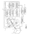
- FIG. 1 is a block diagram schematically showing a configuration of a particle beam irradiation system including a dose distribution measurement device 1 according to Embodiment 1 of the present invention.
- a particle beam 4 is emitted from an irradiation-related device 2 toward a water phantom 3 constituted with a water tank.
- the water phantom 3 is filled with a fluorescent substance containing liquid 5 (generally referred to as a liquid scintillator) that emits light on absorbing the particle beam.
- a fluorescent substance containing liquid 5 generally referred to as a liquid scintillator
- the wall of the water phantom 3 is formed of a transparent material such as an acrylic resin that transmits light.
- an incident window 6 made of a similar material such as an acrylic resin that little absorbs the particle beam.
- the incident window 6 is sometimes formed thinner than the other portion.
- Two cameras of a camera 7 and a camera 8 are provided around the water phantom 3. The two cameras are arranged, for example, on a circle C, which is in a plane perpendicular to the irradiation center axis CA of the particle beam 4 and centered on the irradiation center axis CA, to take an image whose center is on the irradiation center axis CA.
- a dose distribution calculation and evaluation unit 10 calculates and evaluates a dose distribution from the camera images taken with the cameras 7 and 8.
- the dose distribution calculation and evaluation unit 10 includes a camera image processing part 11 for processing the camera images; a spot position determination part 12 for determining a spot position from a camera image processed by the camera image processing part 11 using camera calibration parameters stored in a camera calibration-parameter storage part 17.
- the dose distribution calculation and evaluation unit 10 further includes a dose addition part 13 for calculating and adding a dose at each of spot positions using a pencil beam dose distribution stored in a pencil-beam dose-distribution data storage part 16; and a dose distribution evaluation part 14 for comparing a measured dose distribution that is a result added by the dose addition part 13 with irradiation-region dose distribution data that is planned in a treatment planning device 20 and stored in an irradiation-region dose-distribution data storage part 15 for storing the irradiation-region dose distribution data, to evaluate the measured dose distribution.
- a particle beam 4 which is called a fine pencil beam, is shifted in the two-dimensional directions perpendicular to the beam traveling direction by the irradiation-related device 2 to form a two-dimensional irradiation distribution perpendicular to the beam traveling direction.
- the beam traveling direction is defined as a Z-direction and two directions perpendicular to the Z-direction, i.e., directions in which the beam is shifted are defined as an X-direction and a Y-direction.
- the irradiation-related device 2 includes an X-direction deflection electromagnet and a Y-direction deflection electromagnet for deflecting the particle beam 4 in the X-direction and the Y-direction, respectively.
- the particle beam 4 is emitted with repetition of shifting and staying by the irradiation-related device 2. That is, the particle beam 4 stays at an irradiation position (hereinafter referred to as a spot position) and when the irradiation dose at the spot position reaches a planned irradiation dose, the particle beam 4 is shifted to the next spot position and is emitted until the irradiation dose at the next spot position reaches its planned irradiation dose.
- a spot position an irradiation position
- Repetition of the shifting and staying for an energy level of the particle beam 4 forms a planned irradiation dose distribution, i.e., a two-dimensional irradiation dose distribution in an irradiation region at a Bragg peak position corresponding to the energy level, i.e., at a depth position in the beam traveling direction. Since the irradiation depth is varied by changing the energy level of the particle beam, the energy level of the particle beam is changed to form a planned two-dimensional irradiation dose distribution in an irradiation region at another depth position.
- a planned irradiation dose distribution i.e., a two-dimensional irradiation dose distribution in an irradiation region at a Bragg peak position corresponding to the energy level, i.e., at a depth position in the beam traveling direction. Since the irradiation depth is varied by changing the energy level of the particle beam, the energy level of the particle beam is changed to form a planned two-dimensional irradiation
- a planned irradiation dose distribution is finally formed in a three-dimensional irradiation region by forming two-dimensional irradiation dose distributions with repetition of shifting and staying of the particle beam 4 for each different energy level.
- Such an irradiation method described above is here referred to as a spot scanning irradiation method.
- the treatment planning device 20 calculates control parameters for an irradiation-related controller 21 to control the irradiation-related device 2 and control parameters for an accelerator-related controller 22 to control a not-shown accelerator, and transmits these control parameters to the irradiation-related controller 21 and the accelerator-related controller 22.
- the dose distribution measurement device 1 is used in advance to the therapy in order to check whether the planned dose distribution is formed when the irradiation is performed in accordance with these control parameters.
- a dose distribution measuring method using the dose distribution measurement device 1 according to Embodiment 1 of the present invention will be described with reference to FIGS. 1 to 5 .
- Dose distribution characteristics of a pencil beam are measured first before a three-dimensional dose distribution is measured by the dose distribution measurement device 1.
- the dose distribution characteristics of the pencil beam is measured as a percent depth dose (PDD), which is a distribution in the Z-direction, and as an off center axis ratio (OCR), which is a distribution in the X-Y plane.
- PDD percent depth dose
- OCR off center axis ratio
- the OCR and the PDD can be measured with instruments such as a heretofore known thimble dosimeter and an Advanced Markus®, respectively, or also measured by a method later-described in Embodiment 5.
- Examples of a PDD and an OCR are respectively shown in the graphs (A) and (B) of FIG. 2 . These PDD and OCR are measured for each energy level of the particle beam, and stored in the pencil-beam dose- distribution data storage part 16 of the dose distribution calculation and evaluation unit 10.
- the water phantom 3 is irradiated with the particle beam 4 by the spot scanning irradiation method. Specifically, each spot is irradiated with the particle beam 4 by controlling the accelerator and the irradiation-related device 2 in accordance with the control parameters for each spot position, of the accelerator-related controller 22 and the irradiation-related controller 21.
- the particle beam 4 is scanned with repetition of staying and shifting in the two-dimensional directions perpendicular to the traveling direction over a two-dimensional irradiation region in the water phantom at a depth position corresponding to the energy level.
- a three-dimensional irradiation region is thereby irradiated with the particle beam 4.
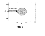
- an image of light emission of the fluorescent substance containing liquid 5 is taken for each irradiation spot position with the cameras 7 and 8. The highest intensity point in the taken image is extracted for each spot position.
- plotting highest intensity points at all spot positions by extracting the highest intensity point in the image taken for each spot position with the camera 7, data as shown in FIG. 3 is obtained.
- a three-dimensional dose distribution that is obtained by the spot irradiation is calculated for each spot position using the PDD and the OCR data stored in the pencil-beam dose- distribution data storage part 16.
- An integrated three-dimensional irradiation distribution can be obtained by integrating the three-dimensional dose distributions at all spot positions.
- a calibration point whose three-dimensional coordinate position is given is implanted in the water phantom so that the calibration point can be positioned at the isocenter of a therapeutic coordinate using a laser pointer or the like in the treatment room.
- the external and internal parameters of each camera are calculated using the calibration point in each camera image.
- the calculated external and internal calibration parameters of each camera are stored in the camera calibration-parameter storage part 17.
- the above measurement method is explained with reference to the flow diagram of FIG. 4 .
- the PDD and the OCR of the pencil beam are measured in advance for each particle-beam energy level, to be stored in the pencil-beam dose-distribution data storage part 16 of the dose distribution calculation and evaluation unit 10 (Step ST1).
- i 1 to obtain measured irradiation dose distribution data at the first spot position (Step ST2).
- the spot position determination part 12 determines the highest intensity position as a three-dimensional position of the spot and calculates a peak dose from the intensity (Step ST4). In determining the three-dimensional position, the camera calibration parameters of each camera stored in the camera calibration-parameter storage part 17 are used.
- the spot position determination part 12 determines the highest intensity position as a three-dimensional position of the spot and calculates the peak dose from the intensity (Step ST4).
- FIG. 5 is a graph showing a two-dimensional distribution in the X- and the Z-directions at a Y-position near the center, that is, a distribution chart of two-and-half--dimensions.
- a three-dimensional irradiation dose distribution such as having point-by-point values in the X, Y, Z three-dimensional volume is obtained.
- the dose distribution evaluation part 14 compares the measured three-dimensional irradiation dose distribution thus obtained with a three-dimensional irradiation dose distribution set in a treatment plan and evaluates the measured dose distribution (Step ST8).
- the dose distribution set in the treatment plan is stored in advance in the irradiation-region dose-distribution data storage part 15 of the dose distribution calculation and evaluation unit 10 from the treatment planning device. Evaluation to what degree the measured irradiation dose distribution conforms to the irradiation dose distribution set in the treatment plan can be performed using a known index such as a gamma index.
- the dose distribution measurement device is capable of easily measuring a dose distribution of a spot scanning irradiation by determining spot positions from an image obtained by taking light emission of the water phantom 3 induced by irradiation of each spot with the two cameras 7 and 8 arranged on the circle C centered on the irradiation center axis CA and using the in advance measured PDD and OCR data of a pencil beam. It is desirable to arrange the two cameras at positions for their imaging angles to be perpendicular to each other.
- the two cameras are not necessarily arranged at the perpendicular positions because determination of camera calibration parameters corresponding to the camera arrangement permits a spot position to be determined from camera images.
- FIG. 6 is a block diagram schematically showing a configuration of a particle beam irradiation system that includes a dose distribution measurement device 100 according to Embodiment 2 of the present invention.
- the same reference numerals as those in FIG. 1 designate the same or equivalent components.
- an OCR measuring camera 9 is added to the configuration of the dose distribution measurement device 1 of Embodiment 1.
- the OCR measuring camera 9 is disposed outside the water phantom 3 and toward the opposite side of the incident window 6 of the water phantom 3 to take an image toward the water phantom 3. The image is taken every time a spot is irradiated, thus obtaining an image corresponding to the OCR for each spot irradiation.
- An OCR distribution calculation part 18 in a dose distribution calculation and evaluation unit 110 calculates OCR data for each spot irradiation from these images.
- the beam diameter is calculated from the camera images and the beam distribution may be assumed to have, for example, a Gaussian distribution.
- the dose addition part 13 calculates and adds, in the step ST5 described in Embodiment 1, an irradiation dose distribution having a peak at the spot position i determined by the spot position determination part 12 using the OCR data calculated by the OCR distribution calculation part 18 and the PDD data stored in the pencil-beam dose-distribution data storage part 16.
- Embodiment 2 there is no need to measure and store in advance the OCR of the pencil beam, and an OCR at the time of actual irradiation is measured to be used for calculation of a dose distribution, thus measuring a dose distribution with higher accuracy.
- FIG. 7 is a block diagram schematically showing a configuration of a particle beam irradiation system that includes a dose distribution measurement device 200 according to Embodiment 3 of the present invention.
- the same reference numerals as those in FIG. 1 designate the same or equivalent components.
- one camera 70 is provided outside the water phantom 3 and disposed, for example, on a circle C, which is in a plane perpendicular to the irradiation center axis CA of the particle beam 4 and centered on the irradiation center axis CA, to take an image whose center is on the irradiation center axis CA.
- FIG. 8 shows an operational flow of the dose distribution measurement device 200 according to Embodiment 3.
- the water phantom 3 is irradiated with the particle beam 4 by the spot scanning irradiation method (Step ST11) and then an image of light emission of the fluorescent substance containing liquid 5 is taken with the camera 70 with a continuous exposure during the irradiation (Step ST12).
- the light emission is recorded as integrated values in a camera image processing part 211 in a dose distribution calculation and evaluation unit 210.
- the image to be recorded may be an image that expresses the light intensity by a grey scale or by iso-intensity curves that connect points of the same light intensity.
- the recorded image is not the dose distribution itself but is values integrated temporally and spatially in the optical axis direction of the camera.
- an image prediction part 30 simulates light emission amounts of the water phantom 3 induced by the dose distribution using irradiation-region dose distribution data set in the treatment planning device 20 and stored in the irradiation-region dose-distribution data storage part 15, and predicts an image as spatially and temporally integrated values that would be taken at the position of the camera 70 from the simulated light emission amounts, to stores the predicted image. Since the light emission of the fluorescent substance containing liquid 5 is almost nonlinear to an irradiation dose, it is preferable to take the nonlinearity into account in the simulation.
- a dose distribution evaluation part 214 compares the dose distribution at the time of actual irradiation with the dose distribution set in the treatment planning device 20 and evaluates the actual dose distribution by comparing the taken image recorded in the camera image processing part 211 with the predicted image stored in the image prediction part 30 and evaluating the taken image (Step ST13).
- the dose distribution measurement device is not capable of measuring directly a dose distribution itself, but is capable of comparing with the one camera configuration an actual irradiation dose distribution with a dose distribution set in the treatment planning device with the one camera configuration, thereby evaluating indirectly the actual irradiation dose distribution.
- FIG. 9 is a block diagram schematically showing a configuration of a particle beam irradiation system that includes a dose distribution measurement device 300 according to Embodiment 4 of the present invention.
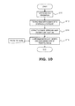
- FIG. 10 is a flow diagram showing an operation of the dose distribution measurement device according to Embodiment 4.
- the same reference numerals as those in FIG. 7 designate the same or equivalent components.
- the one camera 70 is provided outside the water phantom 3 and disposed, for example, on a circle C, which is in a plane perpendicular to the irradiation center axis CA of the particle beam 4 and centered on the irradiation center axis CA, to take an image whose center is on the irradiation center axis CA, as with Embodiment 3.
- Embodiment 4 similarly to Embodiment 3, the water phantom 3 is irradiated with the particle beam 4 by the spot scanning irradiation method (Step ST11) and then an image of light emission of the fluorescent substance containing liquid 5 is taken with the camera 70 with a continuous exposure during the irradiation (Step ST12), thereby to record the light emission as as integrated values in a camera image processing part 311 in a dose distribution calculation and evaluation unit 310.
- the recorded image is not the dose distribution itself but is the values integrated temporally and spatially in the optical axis direction of the camera.
- the image is recorded as data expressing, for example, iso-curves of the light intensity as FIG. 11 .
- a one-dimensional light-intensity distribution calculation part 319 of the dose distribution calculation and evaluation unit 310 extracts from the image a one-dimensional light intensity distribution in a cross section A parallel to the irradiation center axis CA and a one-dimensional light intensity distribution in a cross section B perpendicular to the irradiation center axis CA (Step ST14).
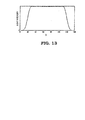
- FIGS. 12 and 13 Examples of the extracted light intensity distributions are shown in FIGS. 12 and 13 .
- FIG. 12 is an example of a one-dimensional, i.e., Z-directional light intensity distribution in the cross section A parallel to the irradiation center axis CA
- FIG. 13 is an example of a one-dimensional, i.e., X-directional light intensity distribution in the cross section B perpendicular the irradiation center axis CA.
- an image prediction part 315 simulates light emission amounts of the water phantom 3 induced by the dose distribution using irradiation-region dose distribution data set in the treatment planning device 20 and stored in the irradiation-region dose-distribution data storage part 15, and predicts an image as spatially and temporally integrated values that would be taken at the position of the camera 70 from the simulated light emission amounts, to extract, from the predicted image, one-dimensional light intensity distributions in a cross section A parallel to the irradiation center axis CA and in a cross section B perpendicular to the irradiation center axis CA.
- the dose distribution evaluation part 314 evaluates the irradiation dose distribution by comparing the one-dimensional light intensity distributions extracted, from the taken image, by the one-dimensional light intensity distribution calculation part 319 with the one-dimensional light intensity distributions extracted, from the predicted image, by the image prediction part 315 (Step ST15).
- FIG. 14 is an operational flow diagram of a dose distribution measurement device according to Embodiment 5 of the present invention.
- the dose distribution measurement device according to Embodiment 5 can obtain pencil beam source data of the particle beam 4 with the configuration of the dose distribution measurement device 300 shown in FIG. 9 , which is the same configuration as Embodiment 4, by irradiating the water phantom 3 for a short time without shifting the particle beam 4 as the pencil beam (Step ST21) and then by taking an image of light emission induced by the pencil beam with the camera 70 (Step ST22).
- one-dimensional light intensity distribution in the Z-direction and a one-dimensional light intensity distribution in the X-direction calculated by a one-dimensional light intensity distribution calculation part 319 are a distribution corresponding to a PDD and a distribution corresponding to an X-directional OCR, respectively, of the source beam.
- the dose distribution evaluation part 314 extract the PDD and the OCR data of the source beam from one-dimensional intensity distributions calculated by the one-dimensional light intensity distribution calculation part 319 (Step ST24).
- the first situation is measurements for registering source beam data for a treatment plan.
- a thimble dosimeter or the like is used for the OCR measurement.
- a Bragg Peak chamber or the like is used for the PDD measurement.
- the other application is distribution measurements for validating in advance whether an irradiation dose of a patient is in accordance with that simulated in the treatment plan.
- the OCR is often measured with a thimble dosimeter or the like
- the PDD is often measured with an Advanced Markus® or the like.
- each Embodiment may be freely combined and/or appropriately modified and/or omitted within the scope and spirit of the invention.
Landscapes
- Health & Medical Sciences (AREA)
- Life Sciences & Earth Sciences (AREA)
- Engineering & Computer Science (AREA)
- Biomedical Technology (AREA)
- High Energy & Nuclear Physics (AREA)
- Molecular Biology (AREA)
- Spectroscopy & Molecular Physics (AREA)
- Physics & Mathematics (AREA)
- General Physics & Mathematics (AREA)
- Radiology & Medical Imaging (AREA)
- Nuclear Medicine, Radiotherapy & Molecular Imaging (AREA)
- Pathology (AREA)
- Animal Behavior & Ethology (AREA)
- General Health & Medical Sciences (AREA)
- Public Health (AREA)
- Veterinary Medicine (AREA)
- Radiation-Therapy Devices (AREA)
- Measurement Of Radiation (AREA)
Abstract
Description
- The present invention relates to a dose distribution measurement device for measuring a dose distribution formed by a particle beam that is used in, for example, particle beam therapies for cancers.
- In cancer radiation therapy, in order to check the energy and the shape of a therapy radiation beam such as an X-ray, an electron beam, and a particle beam, it is necessary to measure a dose distribution in a water phantom mimicking a human body before irradiating a patient with such a beam.
- Furthermore, it is necessary to perform routinely a dose distribution measurement, as quality control on the radiation beam, for adjusting the radiation beam emitting device such as an accelerator and for checking the beam energy distribution and the shape which are different from patient to patient.
- For example in
Patent Document 1, using a water tank mimicking a human body and an ionization chamber equipped with an actuator for changing the chamber position in the water, a dose distribution formed in the water by irradiation with a radiation beam is measured by scanning the ionization chamber. For that reason, a lot of time and effort is needed for only one dose distribution measurement. - Moreover, since the check by the dose distribution measurement is needed in every change of the beam condition, there is a limit on increase in the number of patients treatable with one irradiation device, i.e., in the availability factor of the therapy apparatus.
- In order to overcome such problems, various types of radiation detectors and dose distribution measurement devices have been proposed as devices capable of measuring a dose distribution in a short time.
- For example,
Patent Document 2 discloses a technology in which a substance that emits fluorescence when excited by radiation is contained in a solid phantom of high visible-light transparency to measure a fluorescence intensity by converting the light emission induced by the radiation into electrical signals using a CCD camera or the like. - Furthermore,
Patent Document 3 discloses a particle-beam dose-distribution measurement device including a scintillator unit composed of a scintillation liquid that emits light when irradiated with a proton beam and an imaging unit composed of a CCD camera for taking an image of the scintillator unit in a direction perpendicular to the incident direction of the proton beam, thereby to simultaneously measure scintillations in a plurality of horizontal cross-sectional planes along the incident direction of the particle beam to reconstructed a two-dimensional distribution for each cross-sectional plane and finally to obtain a three-dimensional distribution. -
- Patent Document 1:
JP 2003-047 666 A - Patent Document 2:
JP 2011-133 598 A - Patent Document 3:
JP 2003-079 755 A - There is a scanning irradiation method in particle beam irradiation methods used in particle beam therapy systems that utilize a so-called particle beam such as a proton beam or a carbon beam among radiation beams. The scanning irradiation method is a method of forming a two-dimensional irradiation distribution perpendicular to the beam traveling direction by shifting a fine particle beam, which is called a pencil beam, in the two-dimensional directions perpendicular thereto.
- In addition, since the position where the absorbed dose of the particle beam peaks (referred to as "Bragg peak") depends on the energy of the particle beam, the irradiation position in the beam traveling direction is varied by changing the energy of the particle beam. In the scanning irradiation method, a three-dimensional irradiation field is formed by shifting the pencil beam and changing its energy as described above.
- Because the beam irradiation position thus varies with time in the scanning irradiation method, there arise a problem that the technologies disclosed in
Patent Documents 1 to 3, which are for measuring a dose distribution when the irradiation position does not vary with time, cannot be directly applied to measurement of a dose distribution formed by the scanning irradiation method, or need a significant time when trying to measure a dose distribution formed by the scanning irradiation method. - The present invention has been made to overcome such an above-described problem, and aims at providing a particle-beam dose-distribution measurement device that is capable of measuring, with a simple configuration and in a short time, a particle beam dose distribution formed by a scanning irradiation method.
- The present invention provides a dose distribution measurement device for measuring an irradiation dose distribution to be generated when an irradiation-related device for irradiating an irradiation target with a particle beam as a pencil beam irradiates a three-dimensional target region with the particle beam by scanning, every time an energy level of the particle beam is changed, the particle beam over a two dimensional region of the irradiation target at a depth position corresponding to the energy level with repetition of staying and shifting of the particle beam in a two-dimensional direction perpendicular to the beam traveling direction. The dose distribution measurement device includes:
- a water phantom having a fluorescent substance containing liquid that emits light by being irradiated with the particle beam and provided with an incident window for incident of the particle beam;
- at least two cameras arranged outside the water phantom and on a plane perpendicular to an irradiation center axis in the water phantom, of the particle beam so as to take images of light emission of the fluorescent substance containing liquid; and
- a dose distribution calculation and evaluation unit that includes a camera image processing part processing the images taken with the at least two cameras;
- a camera calibration-parameter storage part storing camera calibration parameters for each of the at least two cameras;
- a spot position determination part determining a position of a spot irradiated with the particle beam during staying of the particle beam, from camera image data processed by the camera image processing part using the camera calibration parameters for each camera which are stored in the camera calibration-parameter storage part;
- a pencil-beam dose-distribution data storage part storing PDD data and OCR data of the pencil beam; and
- a dose addition part calculating an irradiation dose distribution at the spot position determined by the spot position determination part using the PDD data and the OCR data stored in the pencil-beam dose-distribution data storage part and adding the irradiation dose distribution at each of spot positions.
- According to the present invention, a dose distribution measurement device can be provided that is capable of measuring a dose distribution with a simple configuration and in a short time.
-
- FIG. 1
- is a block diagram schematically showing a configuration of a particle beam irradiation system including a dose distribution measurement device according to
Embodiment 1 of the present invention; - FIG. 2
- shows graphs showing examples of a PDD and an OCR of a pencil beam;
- FIG. 3
- is a chart for explaining spot positions determined from a camera image obtained by the dose distribution measurement device according to
Embodiment 1 of the present invention; - FIG. 4
- is a flow diagram showing an operation of the dose distribution measurement device according to
Embodiment 1 of the present invention; - FIG. 5
- is a graph showing an example of a two-and-half--dimensional dose distribution obtained by the dose distribution measurement device according to
Embodiment 1 of the present invention; - FIG. 6
- is a block diagram schematically showing a configuration of a particle beam irradiation system including a dose distribution measurement device according to
Embodiment 2 of the present invention; - FIG. 7
- is a block diagram schematically showing a configuration of a particle beam irradiation system including a dose distribution measurement device according to
Embodiment 3 of the present invention; - FIG. 8
- is a flow diagram showing an operation of the dose distribution measurement device according to
Embodiment 3 of the present invention; - FIG. 9
- is a block diagram schematically showing a configuration of a particle beam irradiation system including a dose distribution measurement device according to Embodiment 4 of the present invention;
- FIG. 10
- is a flow diagram showing an operation of the dose distribution measurement device according to Embodiment 4 of the present invention;
- FIG. 11
- is a chart showing an example of a camera image obtained by the dose distribution measurement device according to Embodiment 4 of the present invention;
- FIG. 12
- is a graph showing an example of a one-dimensional light intensity distribution extracted from a camera image obtained by the dose distribution measurement device according to Embodiment 4 of the present invention;
- FIG. 13
- is a graph showing an example of another one-dimensional light intensity distribution extracted from a camera image obtained by the dose distribution measurement device according to Embodiment 4 of the present invention;
- FIG. 14
- is a flow diagram showing an operation of a dose distribution measurement device according to
Embodiment 5 of the present invention; and - FIG. 15
- is a table for explaining an effect of the present invention.
-
FIG. 1 is a block diagram schematically showing a configuration of a particle beam irradiation system including a dosedistribution measurement device 1 according toEmbodiment 1 of the present invention. A particle beam 4 is emitted from an irradiation-relateddevice 2 toward awater phantom 3 constituted with a water tank. - The
water phantom 3 is filled with a fluorescent substance containing liquid 5 (generally referred to as a liquid scintillator) that emits light on absorbing the particle beam. The wall of thewater phantom 3 is formed of a transparent material such as an acrylic resin that transmits light. At a portion where the particle beam 4 is incident, there is provided an incident window 6 made of a similar material such as an acrylic resin that little absorbs the particle beam. - For little absorption of the particle beam, the incident window 6 is sometimes formed thinner than the other portion. Two cameras of a camera 7 and a
camera 8 are provided around thewater phantom 3. The two cameras are arranged, for example, on a circle C, which is in a plane perpendicular to the irradiation center axis CA of the particle beam 4 and centered on the irradiation center axis CA, to take an image whose center is on the irradiation center axis CA. - A dose distribution calculation and
evaluation unit 10 calculates and evaluates a dose distribution from the camera images taken with thecameras 7 and 8. The dose distribution calculation andevaluation unit 10 includes a cameraimage processing part 11 for processing the camera images; a spotposition determination part 12 for determining a spot position from a camera image processed by the cameraimage processing part 11 using camera calibration parameters stored in a camera calibration-parameter storage part 17. - The dose distribution calculation and
evaluation unit 10 further includes adose addition part 13 for calculating and adding a dose at each of spot positions using a pencil beam dose distribution stored in a pencil-beam dose-distributiondata storage part 16; and a dosedistribution evaluation part 14 for comparing a measured dose distribution that is a result added by thedose addition part 13 with irradiation-region dose distribution data that is planned in atreatment planning device 20 and stored in an irradiation-region dose-distributiondata storage part 15 for storing the irradiation-region dose distribution data, to evaluate the measured dose distribution. - A particle beam 4, which is called a fine pencil beam, is shifted in the two-dimensional directions perpendicular to the beam traveling direction by the irradiation-related
device 2 to form a two-dimensional irradiation distribution perpendicular to the beam traveling direction. - Here, the beam traveling direction is defined as a Z-direction and two directions perpendicular to the Z-direction, i.e., directions in which the beam is shifted are defined as an X-direction and a Y-direction. The irradiation-related
device 2 includes an X-direction deflection electromagnet and a Y-direction deflection electromagnet for deflecting the particle beam 4 in the X-direction and the Y-direction, respectively. - The particle beam 4 is emitted with repetition of shifting and staying by the irradiation-related
device 2. That is, the particle beam 4 stays at an irradiation position (hereinafter referred to as a spot position) and when the irradiation dose at the spot position reaches a planned irradiation dose, the particle beam 4 is shifted to the next spot position and is emitted until the irradiation dose at the next spot position reaches its planned irradiation dose. - Repetition of the shifting and staying for an energy level of the particle beam 4 forms a planned irradiation dose distribution, i.e., a two-dimensional irradiation dose distribution in an irradiation region at a Bragg peak position corresponding to the energy level, i.e., at a depth position in the beam traveling direction. Since the irradiation depth is varied by changing the energy level of the particle beam, the energy level of the particle beam is changed to form a planned two-dimensional irradiation dose distribution in an irradiation region at another depth position.
- In this way, a planned irradiation dose distribution is finally formed in a three-dimensional irradiation region by forming two-dimensional irradiation dose distributions with repetition of shifting and staying of the particle beam 4 for each different energy level. Such an irradiation method described above is here referred to as a spot scanning irradiation method.
- In order to form an irradiation dose distribution in an irradiation region needed for a diseased part of a patient using the above spot scanning irradiation method, the
treatment planning device 20 calculates control parameters for an irradiation-relatedcontroller 21 to control the irradiation-relateddevice 2 and control parameters for an accelerator-relatedcontroller 22 to control a not-shown accelerator, and transmits these control parameters to the irradiation-relatedcontroller 21 and the accelerator-relatedcontroller 22. - While the diseased part of the patient is irradiated with the particle beam 4 with repetition of shifting and staying in accordance with these control parameters for the irradiation- related
controller 21 and the accelerator-relatedcontroller 22 during the therapy, a dose distribution in the diseased part of the patient cannot be directly measured. - For that reason, the dose
distribution measurement device 1 is used in advance to the therapy in order to check whether the planned dose distribution is formed when the irradiation is performed in accordance with these control parameters. - A dose distribution measuring method using the dose
distribution measurement device 1 according toEmbodiment 1 of the present invention will be described with reference toFIGS. 1 to 5 . Dose distribution characteristics of a pencil beam are measured first before a three-dimensional dose distribution is measured by the dosedistribution measurement device 1. - The dose distribution characteristics of the pencil beam is measured as a percent depth dose (PDD), which is a distribution in the Z-direction, and as an off center axis ratio (OCR), which is a distribution in the X-Y plane. The OCR and the PDD can be measured with instruments such as a heretofore known thimble dosimeter and an Advanced Markus®, respectively, or also measured by a method later-described in
Embodiment 5. - Examples of a PDD and an OCR are respectively shown in the graphs (A) and (B) of
FIG. 2 . These PDD and OCR are measured for each energy level of the particle beam, and stored in the pencil-beam dose- distributiondata storage part 16 of the dose distribution calculation andevaluation unit 10. - Next, with the configuration of
FIG. 1 , thewater phantom 3 is irradiated with the particle beam 4 by the spot scanning irradiation method. Specifically, each spot is irradiated with the particle beam 4 by controlling the accelerator and the irradiation-relateddevice 2 in accordance with the control parameters for each spot position, of the accelerator-relatedcontroller 22 and the irradiation-relatedcontroller 21. - Every time the energy level of the particle beam 4 is changed, the particle beam 4 is scanned with repetition of staying and shifting in the two-dimensional directions perpendicular to the traveling direction over a two-dimensional irradiation region in the water phantom at a depth position corresponding to the energy level.
- A three-dimensional irradiation region is thereby irradiated with the particle beam 4. At this time, an image of light emission of the fluorescent
substance containing liquid 5 is taken for each irradiation spot position with thecameras 7 and 8. The highest intensity point in the taken image is extracted for each spot position. - For example, plotting highest intensity points at all spot positions by extracting the highest intensity point in the image taken for each spot position with the camera 7, data as shown in
FIG. 3 is obtained. - A three-dimensional dose distribution that is obtained by the spot irradiation is calculated for each spot position using the PDD and the OCR data stored in the pencil-beam dose- distribution
data storage part 16. An integrated three-dimensional irradiation distribution can be obtained by integrating the three-dimensional dose distributions at all spot positions. - In order to three-dimensionally measure a three-dimensional position by cameras in two or more directions, it is necessary to perform calibration for the cameras in advance. To be more specific, external camera parameters (mounting position and angle) and internal camera parameters (such as an image center and distortion), which are calibration parameters of the cameras, can be determined by a known method.
- Here, a calibration point whose three-dimensional coordinate position is given is implanted in the water phantom so that the calibration point can be positioned at the isocenter of a therapeutic coordinate using a laser pointer or the like in the treatment room. The external and internal parameters of each camera are calculated using the calibration point in each camera image. The calculated external and internal calibration parameters of each camera are stored in the camera calibration-
parameter storage part 17. - The above measurement method is explained with reference to the flow diagram of
FIG. 4 . As described above, the PDD and the OCR of the pencil beam are measured in advance for each particle-beam energy level, to be stored in the pencil-beam dose-distributiondata storage part 16 of the dose distribution calculation and evaluation unit 10 (Step ST1). - Here, the number of positions of the spots to be irradiated is assumed to be n. Firstly, i is set to be one (i = 1) to obtain measured irradiation dose distribution data at the first spot position (Step ST2). The control parameters of the irradiation-related
controller 21 and the accelerator-relatedcontroller 22 are set for the first position spot to be irradiated, and then images of light emission of thewater phantom 3 are taken with thecameras 7 and 8 when the spot I = 1 is irradiated (Step ST3). - From camera images taken with the
cameras 7 and 8, the spotposition determination part 12 determines the highest intensity position as a three-dimensional position of the spot and calculates a peak dose from the intensity (Step ST4). In determining the three-dimensional position, the camera calibration parameters of each camera stored in the camera calibration-parameter storage part 17 are used. - In addition, in a case of the intensity and the absorbed dose being in a nonlinear relationship, tabulating the nonlinear relationship between the intensity and the absorbed dose in a correspondence table would allow for simple conversion from the intensity to the absorbed dose.
- The
dose addition part 13 calculates an irradiation dose distribution that has the peak at the determined spot position I = 1 using the PDD and the OCR data stored in the pencil-beam dose-distribution data storage part, to obtain a three-dimensional irradiation dose distribution (Step ST5). - Next, the increment of i = i + 1 is performed (Step ST7), i.e., i is increased to two (i = 2), and then the control parameters of the irradiation-related
controller 21 and the accelerator-relatedcontroller 22 are set for the second position spot to be irradiated. - And images of light emission of the
water phantom 3 are taken with thecameras 7 and 8 when the spot i = 2 is irradiated (Step ST3). From camera images taken with thecameras 7 and 8, the spotposition determination part 12 determines the highest intensity position as a three-dimensional position of the spot and calculates the peak dose from the intensity (Step ST4). - An irradiation dose distribution that has a peak at the determined peak spot position i =2 is calculated using the PDD and the OCR data stored in the pencil-beam dose-distribution data storage part, to be added to the first three-dimensional irradiation dose distribution (Step ST5).
- In this way, calculated three-dimensional irradiation dose distributions are added until i becomes i = n ("NO" in ST6). At the time of finishing irradiation at all spot positions, i.e., i = n ("YES" in ST6), an irradiation dose distribution obtained by the addition is a measured irradiation dose distribution. An example of obtained data is shown in
FIG. 5 . -
FIG. 5 is a graph showing a two-dimensional distribution in the X- and the Z-directions at a Y-position near the center, that is, a distribution chart of two-and-half--dimensions. In practice, a three-dimensional irradiation dose distribution such as having point-by-point values in the X, Y, Z three-dimensional volume is obtained. The dosedistribution evaluation part 14 compares the measured three-dimensional irradiation dose distribution thus obtained with a three-dimensional irradiation dose distribution set in a treatment plan and evaluates the measured dose distribution (Step ST8). - The dose distribution set in the treatment plan is stored in advance in the irradiation-region dose-distribution
data storage part 15 of the dose distribution calculation andevaluation unit 10 from the treatment planning device. Evaluation to what degree the measured irradiation dose distribution conforms to the irradiation dose distribution set in the treatment plan can be performed using a known index such as a gamma index. - As described above, the dose distribution measurement device according to
Embodiment 1 of the present invention is capable of easily measuring a dose distribution of a spot scanning irradiation by determining spot positions from an image obtained by taking light emission of thewater phantom 3 induced by irradiation of each spot with the twocameras 7 and 8 arranged on the circle C centered on the irradiation center axis CA and using the in advance measured PDD and OCR data of a pencil beam. It is desirable to arrange the two cameras at positions for their imaging angles to be perpendicular to each other. - It should be noted that the two cameras are not necessarily arranged at the perpendicular positions because determination of camera calibration parameters corresponding to the camera arrangement permits a spot position to be determined from camera images. In addition, it is sufficient to arrange at least two cameras; three or more cameras may as well be arranged. More cameras allows for determination of a spot position with higher accuracy.
-
FIG. 6 is a block diagram schematically showing a configuration of a particle beam irradiation system that includes a dosedistribution measurement device 100 according toEmbodiment 2 of the present invention. InFIG. 6 , the same reference numerals as those inFIG. 1 designate the same or equivalent components. - In the dose
distribution measurement device 100 according toEmbodiment 2, anOCR measuring camera 9 is added to the configuration of the dosedistribution measurement device 1 ofEmbodiment 1. TheOCR measuring camera 9 is disposed outside thewater phantom 3 and toward the opposite side of the incident window 6 of thewater phantom 3 to take an image toward thewater phantom 3. The image is taken every time a spot is irradiated, thus obtaining an image corresponding to the OCR for each spot irradiation. - An OCR
distribution calculation part 18 in a dose distribution calculation andevaluation unit 110 calculates OCR data for each spot irradiation from these images. In calculating the OCR data, the beam diameter is calculated from the camera images and the beam distribution may be assumed to have, for example, a Gaussian distribution. - In
Embodiment 2, thedose addition part 13 calculates and adds, in the step ST5 described inEmbodiment 1, an irradiation dose distribution having a peak at the spot position i determined by the spotposition determination part 12 using the OCR data calculated by the OCRdistribution calculation part 18 and the PDD data stored in the pencil-beam dose-distributiondata storage part 16. - As described above, according to
Embodiment 2, there is no need to measure and store in advance the OCR of the pencil beam, and an OCR at the time of actual irradiation is measured to be used for calculation of a dose distribution, thus measuring a dose distribution with higher accuracy. -
FIG. 7 is a block diagram schematically showing a configuration of a particle beam irradiation system that includes a dosedistribution measurement device 200 according toEmbodiment 3 of the present invention. InFIG. 7 , the same reference numerals as those inFIG. 1 designate the same or equivalent components. - In
Embodiment 3, onecamera 70 is provided outside thewater phantom 3 and disposed, for example, on a circle C, which is in a plane perpendicular to the irradiation center axis CA of the particle beam 4 and centered on the irradiation center axis CA, to take an image whose center is on the irradiation center axis CA. -
FIG. 8 shows an operational flow of the dosedistribution measurement device 200 according toEmbodiment 3. Thewater phantom 3 is irradiated with the particle beam 4 by the spot scanning irradiation method (Step ST11) and then an image of light emission of the fluorescentsubstance containing liquid 5 is taken with thecamera 70 with a continuous exposure during the irradiation (Step ST12). - The light emission is recorded as integrated values in a camera
image processing part 211 in a dose distribution calculation andevaluation unit 210. The image to be recorded may be an image that expresses the light intensity by a grey scale or by iso-intensity curves that connect points of the same light intensity. The recorded image is not the dose distribution itself but is values integrated temporally and spatially in the optical axis direction of the camera. - Hence, an
image prediction part 30 simulates light emission amounts of thewater phantom 3 induced by the dose distribution using irradiation-region dose distribution data set in thetreatment planning device 20 and stored in the irradiation-region dose-distributiondata storage part 15, and predicts an image as spatially and temporally integrated values that would be taken at the position of thecamera 70 from the simulated light emission amounts, to stores the predicted image. Since the light emission of the fluorescentsubstance containing liquid 5 is almost nonlinear to an irradiation dose, it is preferable to take the nonlinearity into account in the simulation. - A dose
distribution evaluation part 214 compares the dose distribution at the time of actual irradiation with the dose distribution set in thetreatment planning device 20 and evaluates the actual dose distribution by comparing the taken image recorded in the cameraimage processing part 211 with the predicted image stored in theimage prediction part 30 and evaluating the taken image (Step ST13). - As described above, the dose distribution measurement device according to
Embodiment 3 is not capable of measuring directly a dose distribution itself, but is capable of comparing with the one camera configuration an actual irradiation dose distribution with a dose distribution set in the treatment planning device with the one camera configuration, thereby evaluating indirectly the actual irradiation dose distribution. -
FIG. 9 is a block diagram schematically showing a configuration of a particle beam irradiation system that includes a dosedistribution measurement device 300 according to Embodiment 4 of the present invention. AndFIG. 10 is a flow diagram showing an operation of the dose distribution measurement device according to Embodiment 4. InFIG. 9 , the same reference numerals as those inFIG. 7 designate the same or equivalent components. - In Embodiment 4, the one
camera 70 is provided outside thewater phantom 3 and disposed, for example, on a circle C, which is in a plane perpendicular to the irradiation center axis CA of the particle beam 4 and centered on the irradiation center axis CA, to take an image whose center is on the irradiation center axis CA, as withEmbodiment 3. - In Embodiment 4, similarly to
Embodiment 3, thewater phantom 3 is irradiated with the particle beam 4 by the spot scanning irradiation method (Step ST11) and then an image of light emission of the fluorescentsubstance containing liquid 5 is taken with thecamera 70 with a continuous exposure during the irradiation (Step ST12), thereby to record the light emission as as integrated values in a cameraimage processing part 311 in a dose distribution calculation andevaluation unit 310. The recorded image is not the dose distribution itself but is the values integrated temporally and spatially in the optical axis direction of the camera. - The image is recorded as data expressing, for example, iso-curves of the light intensity as
FIG. 11 . A one-dimensional light-intensitydistribution calculation part 319 of the dose distribution calculation andevaluation unit 310 extracts from the image a one-dimensional light intensity distribution in a cross section A parallel to the irradiation center axis CA and a one-dimensional light intensity distribution in a cross section B perpendicular to the irradiation center axis CA (Step ST14). - Examples of the extracted light intensity distributions are shown in
FIGS. 12 and13 .FIG. 12 is an example of a one-dimensional, i.e., Z-directional light intensity distribution in the cross section A parallel to the irradiation center axis CA, andFIG. 13 is an example of a one-dimensional, i.e., X-directional light intensity distribution in the cross section B perpendicular the irradiation center axis CA. - Meanwhile, an
image prediction part 315 simulates light emission amounts of thewater phantom 3 induced by the dose distribution using irradiation-region dose distribution data set in thetreatment planning device 20 and stored in the irradiation-region dose-distributiondata storage part 15, and predicts an image as spatially and temporally integrated values that would be taken at the position of thecamera 70 from the simulated light emission amounts, to extract, from the predicted image, one-dimensional light intensity distributions in a cross section A parallel to the irradiation center axis CA and in a cross section B perpendicular to the irradiation center axis CA. - The dose
distribution evaluation part 314 evaluates the irradiation dose distribution by comparing the one-dimensional light intensity distributions extracted, from the taken image, by the one-dimensional light intensitydistribution calculation part 319 with the one-dimensional light intensity distributions extracted, from the predicted image, by the image prediction part 315 (Step ST15). -
FIG. 14 is an operational flow diagram of a dose distribution measurement device according toEmbodiment 5 of the present invention. The dose distribution measurement device according toEmbodiment 5 can obtain pencil beam source data of the particle beam 4 with the configuration of the dosedistribution measurement device 300 shown inFIG. 9 , which is the same configuration as Embodiment 4, by irradiating thewater phantom 3 for a short time without shifting the particle beam 4 as the pencil beam (Step ST21) and then by taking an image of light emission induced by the pencil beam with the camera 70 (Step ST22). - When the
camera 70 is disposed as shown inFIG.9 , for example, one-dimensional light intensity distribution in the Z-direction and a one-dimensional light intensity distribution in the X-direction calculated by a one-dimensional light intensity distribution calculation part 319 (Step ST23) are a distribution corresponding to a PDD and a distribution corresponding to an X-directional OCR, respectively, of the source beam. - Hence, the dose
distribution evaluation part 314 extract the PDD and the OCR data of the source beam from one-dimensional intensity distributions calculated by the one-dimensional light intensity distribution calculation part 319 (Step ST24). - When one more camera is further disposed in a direction perpendicular to the
camera 70, i.e., at the position of thecamera 8 shown inFIG.1 , a distribution corresponding to a Y-directional OCR of the source beam can be obtained. In a case of the intensity and the absorbed dose being in a nonlinear relationship, tabulating the nonlinear relationship therebetween as a correspondence table allows for easy conversion from the light intensity to the absorbed dose. - In this way, by taking with a camera an image of light emission of the liquid containing a fluorescent substance induced by the short irradiation with the pencil beam allows for obtaining easily source beam data corresponding to the PDD and the OCR of the pencil beam.
- From the object of particle beam therapy, two situations and two measurements, i.e., four cases in total are conceivable as shown in
FIG. 15 . The first situation is measurements for registering source beam data for a treatment plan. In the measurement, a thimble dosimeter or the like is used for the OCR measurement. - Also in the measurement, a Bragg Peak chamber or the like is used for the PDD measurement. The other application (situation) is distribution measurements for validating in advance whether an irradiation dose of a patient is in accordance with that simulated in the treatment plan.
- In the distribution measurements, the OCR is often measured with a thimble dosimeter or the like, and the PDD is often measured with an Advanced Markus® or the like.
- Employing each technique according to the present invention allows for covering all the four cases, thus exhibiting the feature of performing two-dimensional, two-and-half-dimensional, or three-dimensional distribution measurement.
- In the present invention, each Embodiment may be freely combined and/or appropriately modified and/or omitted within the scope and spirit of the invention.
-
- 1
- dose distribution measurement device
- 2
- irradiation-related device
- 3
- water phantom
- 4
- particle beam
- 5
- fluorescent substance containing liquid
- 6
- incident window
- 7
- camera
- 8
- camera
- 9
- OCR measuring camera
- 10
- dose distribution calculation and evaluation unit
- 11
- camera image processing part
- 12
- spot position determination part
- 13
- dose addition part
- 14
- dose distribution evaluation part
- 15
- irradiation-region dose-distribution data storage part
- 16
- pencil-beam dose-distribution data storage part
- 17
- camera calibration-parameter storage part
- 18
- OCR distribution calculation part
- 20
- treatment planning device
- 21
- irradiation-related controller
- 22
- accelerator-related
controller 22 - 30
- image prediction part
- 70
- camera
- 100
- dose distribution measurement device
- 110
- dose distribution calculation and evaluation unit
- 200
- dose distribution measurement device
- 210
- dose distribution calculation and evaluation unit
- 211
- camera image processing part
- 214
- dose distribution evaluation part
- 300
- dose distribution measurement device
- 310
- dose distribution calculation and evaluation unit
- 311
- camera image processing part
- 314
- dose distribution evaluation part
- 315
- image prediction part
- 319
- one-dimensional light intensity distribution calculation part.
Claims (6)
- A dose distribution measurement device for measuring an irradiation dose distribution to be generated when an irradiation-related device for irradiating an irradiation target with a particle beam as a pencil beam irradiates a three-dimensional target region with the particle beam by scanning, every time an energy level of the particle beam is changed, the particle beam over a two dimensional region of the irradiation target at a depth position corresponding to the energy level with repetition of staying and shifting of the particle beam in a two-dimensional direction perpendicular to the beam traveling direction,
the dose distribution measurement device comprising:- a water phantom having a fluorescent substance containing liquid that emits light by being irradiated with the particle beam and provided with an incident window for incident of the particle beam;- at least two cameras arranged outside the water phantom and on a plane perpendicular to an irradiation center axis in the water phantom, of the particle beam so as to take images of light emission of the fluorescent substance containing liquid; and- a dose distribution calculation and evaluation unit including:- a camera image processing part processing the images taken with the at least two cameras;- a camera calibration-parameter storage part storing camera calibration parameters for each of the at least two cameras;- a spot position determination part determining a position of a spot irradiated with the particle beam during staying of the particle beam, from camera image data processed by the camera image processing part using the camera calibration parameters for each camera which are stored in the camera calibration-parameter storage part;- a pencil-beam dose-distribution data storage part storing PDD data and OCR data of the pencil beam; and- a dose addition part calculating an irradiation dose distribution at the spot position determined by the spot position determination part using the PDD data and the OCR data stored in the pencil-beam dose-distribution data storage part and adding the irradiation dose distribution at each of spot positions. - The dose distribution measurement device set forth in claim 1 further comprising:an OCR measuring camera provided outside the water phantom and on a side opposite the incident side of the particle beam,wherein the dose distribution calculation and evaluation unit further includes an OCR distribution calculation part calculating an OCR at each spot position from an image taken with the OCR measuring camera andwherein the dose addition part calculates an irradiation dose distribution at a spot position determined by the spot position determination part using the OCR calculated by the OCR distribution calculation part instead of the OCR data stored in the pencil-beam dose-distribution data storage part.
- The dose distribution measurement device set forth in claim 1 or 2, wherein the dose distribution calculation and evaluation unit further includes an irradiation-region dose-distribution data storage part storing a dose distribution data for an irradiation region set in a treatment planning device, and compares a measured irradiation dose distribution obtained by adding all irradiation dose distributions at determined spot positions by the dose addition part with the dose distribution data stored in the irradiation-region dose-distribution data storage part, thereby to evaluate the measured irradiation dose distribution.
- A dose distribution measurement device for measuring an irradiation dose distribution to be generated when an irradiation-related device for irradiating an irradiation target with a particle beam as a pencil beam irradiates a three-dimensional target region with the particle beam by scanning, every time an energy level of the particle beam is changed, the particle beam over a two dimensional region of the irradiation target at a depth position corresponding to the energy level with repetition of staying and shifting of the particle beam in a two-dimensional direction perpendicular to the beam traveling direction,
he dose distribution measurement device comprising:- a water phantom having a fluorescent substance containing liquid that emits light by being irradiated with the particle beam and provided with an incident window for incident of the particle beam;- one camera disposed outside the water phantom and on a plane perpendicular to an irradiation center axis in the water phantom, of the particle beam so as to take images of light emission of the fluorescent substance containing liquid; and- a dose distribution calculation and evaluation unit including:- a camera image processing part processing an image taken with the one camera;- an irradiation-region dose-distribution data storage part storing a dose distribution data for an irradiation region set in a treatment planning device;- an image prediction part predicting a camera image taken at the position of the one camera from the dose distribution data stored in the irradiation-region dose-distribution data storage part, to store the predicted image; and- a dose distribution evaluation part evaluating the one camera taken image processed by the camera image processing part with the predicted image stored in the image prediction part, to evaluate the one camera taken image. - The dose distribution measurement device set forth in claim 4,
wherein the dose distribution calculation and evaluation unit further includes a one-dimensional light intensity distribution calculation part extracting a one-dimensional light intensity distribution from the camera image processed by the camera image processing part, and wherein the dose distribution evaluation part extracts a one-dimensional light intensity distribution from the predicted image stored in the image prediction part and compares the one-dimensional light intensity distribution calculated by the one-dimensional light intensity distribution calculation part with the one-dimensional light intensity distribution extracted from the predicted image thereby to evaluate the calculated one-dimensional light intensity distribution. - A dose distribution measurement device that measures pencil beam source data of a particle beam,
the dose distribution measurement device comprising:- a water phantom having a fluorescent substance containing liquid that emits light by being irradiated with the particle beam and provided with an incident window for incident of the particle beam;- one camera disposed around the water phantom and on a plane perpendicular to an irradiation center axis in the water phantom, of the particle beam so as to take images of light emission of the fluorescent substance containing liquid; and- a dose distribution calculation and evaluation unit including:- a camera image processing part processing an image taken with the one camera;- a one-dimensional light intensity distribution calculation part extracting a one-dimensional light intensity distribution from an image processed by the camera image processing part from a camera image, taken with the one camera, of light emission induced by irradiation of the fluorescent substance containing liquid with the particle beam as the pencil beam during staying of the particle beam;- a dose distribution evaluation part obtaining PDD data and OCR data of the particle beam as the pencil beam from the one-dimensional light intensity distribution extracted by the one-dimensional light intensity distribution calculation part.
Applications Claiming Priority (1)
| Application Number | Priority Date | Filing Date | Title |
|---|---|---|---|
| PCT/JP2012/083641 WO2014102929A1 (en) | 2012-12-26 | 2012-12-26 | Dose distribution measurement device |
Publications (2)
| Publication Number | Publication Date |
|---|---|
| EP2939708A1 true EP2939708A1 (en) | 2015-11-04 |
| EP2939708A4 EP2939708A4 (en) | 2016-08-10 |
Family
ID=51020088
Family Applications (1)
| Application Number | Title | Priority Date | Filing Date |
|---|---|---|---|
| EP12891049.4A Withdrawn EP2939708A4 (en) | 2012-12-26 | 2012-12-26 | DEVICE FOR MEASURING DOSING DISTRIBUTION |
Country Status (6)
| Country | Link |
|---|---|
| US (1) | US20150306427A1 (en) |
| EP (1) | EP2939708A4 (en) |
| JP (1) | JP5918865B2 (en) |
| CN (1) | CN104870054B (en) |
| TW (1) | TWI463163B (en) |
| WO (1) | WO2014102929A1 (en) |
Cited By (2)
| Publication number | Priority date | Publication date | Assignee | Title |
|---|---|---|---|---|
| WO2018217763A1 (en) * | 2017-05-26 | 2018-11-29 | Accuray Incorporated | Radiation based treatment beam position calibration and verification |
| WO2020020840A1 (en) * | 2018-07-23 | 2020-01-30 | Ion Beam Applications S.A. | Scintillating detectors for quality assurance of a therapy photon beam |
Families Citing this family (22)
| Publication number | Priority date | Publication date | Assignee | Title |
|---|---|---|---|---|
| JP6062073B2 (en) * | 2014-01-10 | 2017-01-18 | 三菱電機株式会社 | Particle beam irradiation equipment |
| GB2530790B (en) | 2014-10-02 | 2016-10-19 | Vision Rt Ltd | Method of calibrating a patient monitoring system for use with a radiotherapy treatment apparatus |
| NL2014012B1 (en) * | 2014-12-18 | 2016-10-12 | Univ Groningen | Imaging method and system for verification of a treatment plan in hadron therapy. |
| JP6493859B2 (en) * | 2015-04-09 | 2019-04-03 | 公益財団法人若狭湾エネルギー研究センター | Radiation monitoring system |
| US10661101B2 (en) * | 2015-07-01 | 2020-05-26 | Hitachi, Ltd. | Dose distribution calculation device, particle beam therapy system, and dose distribution calculation method |
| WO2017108427A1 (en) * | 2015-12-23 | 2017-06-29 | Agfa Healthcare Nv | Radiation dosimeter |
| JP7126710B2 (en) * | 2017-02-03 | 2022-08-29 | ザ ユニバーシティ オブ リバプール | phantom |
| GB2565119A (en) * | 2017-08-02 | 2019-02-06 | Vision Rt Ltd | Method of calibrating a patient monitoring system for use with a radiotherapy treatment apparatus |
| CN107875524B (en) * | 2017-11-10 | 2020-06-12 | 上海联影医疗科技有限公司 | Radiotherapy system, phantom and isocenter calibration method |
| GB2571122B (en) * | 2018-02-19 | 2020-04-22 | Elekta ltd | Water tank apparatus |
| CN110354402B (en) * | 2018-04-28 | 2021-05-11 | 北京铭杰医疗科技有限公司 | Electron beam dose measuring system and detection method |
| JP7125109B2 (en) * | 2018-09-21 | 2022-08-24 | 国立研究開発法人量子科学技術研究開発機構 | Data analysis device, comparison display device, treatment plan data editing device, dose distribution measuring method, program and dose distribution measuring device |
| CN109394215B (en) * | 2018-11-16 | 2022-04-29 | 上海京悦机械有限公司 | Medical instrument die body, clamp and machining process |
| DE102020200400B4 (en) | 2019-02-14 | 2021-10-28 | Siemens Healthcare Gmbh | Controlled irradiation of an object |
| KR102232327B1 (en) * | 2019-03-14 | 2021-03-29 | 충남대학교산학협력단 | Apparatus for brachytherapy radiotherapy dosimetry and method of the same |
| CN111973892B (en) * | 2019-05-23 | 2022-07-08 | 千才生医股份有限公司 | Dose distribution reconstruction method for pen-tip proton beam scanning system for radiotherapy |
| CN110652661B (en) * | 2019-09-30 | 2021-03-26 | 中北大学 | Convolution superposition dosage calculation system |
| IT202000007780A1 (en) * | 2020-04-14 | 2021-10-14 | Istituto Naz Di Fisica Nucleare I N F N | Silicon carbide dosimetry detector |
| CN112083467B (en) * | 2020-09-28 | 2022-05-31 | 中国科学院近代物理研究所 | Three-dimensional dose measurement detection system of particle therapy device |
| CN113406686A (en) * | 2021-06-16 | 2021-09-17 | 中国科学院近代物理研究所 | Ion beam three-dimensional dose distribution detection device and method |
| CN118732007B (en) * | 2024-06-09 | 2025-10-03 | 中国科学技术大学 | A method for calculating proton radiation dose in a magnetic field |
| CN121741801A (en) * | 2024-09-25 | 2026-03-27 | 广东省新兴激光等离子体技术研究院 | Three-dimensional radiation dose testing method based on water ionization and radiation dosimeter |
Family Cites Families (51)
| Publication number | Priority date | Publication date | Assignee | Title |
|---|---|---|---|---|
| US5596653A (en) * | 1991-04-09 | 1997-01-21 | Mitsubishi Denki Kabushiki Kaisha | Radiation therapy treatment planning system |
| JP3841898B2 (en) * | 1996-11-21 | 2006-11-08 | 三菱電機株式会社 | Deep dose measurement system |
| US6256591B1 (en) * | 1996-11-26 | 2001-07-03 | Mitsubishi Denki Kabushiki Kaisha | Method of forming energy distribution |
| US6025717A (en) * | 1997-06-23 | 2000-02-15 | Fonar Corporation | Diagnostic simulator for MRI |
| DE19907774A1 (en) * | 1999-02-19 | 2000-08-31 | Schwerionenforsch Gmbh | Method for verifying the calculated radiation dose of an ion beam therapy system |
| JP2001346894A (en) * | 2000-06-08 | 2001-12-18 | Mitsubishi Electric Corp | Dose distribution measuring device |
| WO2002024278A1 (en) * | 2000-09-22 | 2002-03-28 | Numerix Llc | Improved radiation therapy treatment method |
| US20020122117A1 (en) * | 2000-12-26 | 2002-09-05 | Masamichi Nakagawa | Camera device, camera system and image processing method |
| WO2002096096A1 (en) * | 2001-05-16 | 2002-11-28 | Zaxel Systems, Inc. | 3d instant replay system and method |
| JP2002360715A (en) * | 2001-06-08 | 2002-12-17 | Mitsubishi Electric Corp | Dose distribution measuring device and dose distribution measuring system |
| JP3839687B2 (en) * | 2001-08-07 | 2006-11-01 | 三菱電機株式会社 | Water phantom type dose distribution measuring device |
| JP2003079755A (en) * | 2001-09-12 | 2003-03-18 | Wakasawan Energ Kenkyu Center | Apparatus and method for measuring particle dose distribution by optical CT |
| JP4146648B2 (en) * | 2002-02-14 | 2008-09-10 | 三菱電機株式会社 | Absorbed dose distribution measuring device |
| JP4147059B2 (en) * | 2002-07-03 | 2008-09-10 | 株式会社トプコン | Calibration data measuring device, measuring method and measuring program, computer-readable recording medium, and image data processing device |
| US7307654B2 (en) * | 2002-10-31 | 2007-12-11 | Hewlett-Packard Development Company, L.P. | Image capture and viewing system and method for generating a synthesized image |
| JP2004321408A (en) * | 2003-04-23 | 2004-11-18 | Mitsubishi Electric Corp | Radiation irradiation device and radiation irradiation method |
| CA2574675C (en) * | 2004-07-20 | 2015-11-24 | Resonant Medical Inc. | Calibrating imaging devices |
| US7208748B2 (en) * | 2004-07-21 | 2007-04-24 | Still River Systems, Inc. | Programmable particle scatterer for radiation therapy beam formation |
| JP4585815B2 (en) * | 2004-09-03 | 2010-11-24 | キヤノン株式会社 | Information processing apparatus, imaging system, absorption coefficient correction method, and computer program |
| US7629598B2 (en) * | 2005-02-04 | 2009-12-08 | Mitsubishi Denki Kabushiki Kaisha | Particle beam irradiation method using depth and lateral direction irradiation field spread and particle beam irradiation apparatus used for the same |
| CN1980709A (en) * | 2005-02-04 | 2007-06-13 | 三菱电机株式会社 | Particle beam irradiation method and particle beam irradiation apparatus using the method |
| US20070249925A1 (en) * | 2005-08-29 | 2007-10-25 | Martin Hoheisel | X-Ray Diagnostic Device for Mammography |
| US7450687B2 (en) * | 2005-09-29 | 2008-11-11 | University Of Medicine And Dentistry Of New Jersey | Method for verification of intensity modulated radiation therapy |
| CN101213476B (en) * | 2005-12-28 | 2011-07-13 | 松下电器产业株式会社 | Article detection device and article detection method |
| CN2932411Y (en) * | 2006-01-25 | 2007-08-08 | 南方医科大学 | Dose measuring water tank of stereotactic radiotherapy system |
| US8406562B2 (en) * | 2006-08-11 | 2013-03-26 | Geo Semiconductor Inc. | System and method for automated calibration and correction of display geometry and color |
| US20110042580A1 (en) * | 2006-09-06 | 2011-02-24 | University Health Network | Fluorescence quantification and image acquisition in highly turbid media |
| CN100432699C (en) * | 2006-12-29 | 2008-11-12 | 成都川大奇林科技有限责任公司 | Method for measuring photon beam energy spectrum of medical accelerator |
| EP2116277A1 (en) * | 2008-05-06 | 2009-11-11 | Ion Beam Applications S.A. | Device and method for particle therapy monitoring and verification |
| WO2009140757A1 (en) * | 2008-05-20 | 2009-11-26 | University Health Network | Device and method for fluorescence-based imaging and monitoring |
| CN101290354A (en) * | 2008-06-12 | 2008-10-22 | 中国测试技术研究院电离辐射研究所 | Exchanging detector measuring method for radiotherapy equipment clinical dosage distribution |
| EP2140913A1 (en) * | 2008-07-03 | 2010-01-06 | Ion Beam Applications S.A. | Device and method for particle therapy verification |
| JP5288542B2 (en) * | 2008-07-30 | 2013-09-11 | 独立行政法人放射線医学総合研究所 | Irradiation dose confirmation system and irradiation dose confirmation method |
| US8294762B2 (en) * | 2008-10-10 | 2012-10-23 | Fujifilm Corporation | Three-dimensional shape measurement photographing apparatus, method, and program |
| US8340245B2 (en) * | 2009-06-05 | 2012-12-25 | Sentinel Scanning Corporation | Transportation container inspection system and method |
| EP2471579B1 (en) * | 2009-06-09 | 2015-10-14 | Mitsubishi Electric Corporation | Particle beam irradiation apparatus |
| WO2011005862A2 (en) * | 2009-07-07 | 2011-01-13 | The Board Of Regents Of The University Of Texas System | Liquid scintillator for 3d dosimetry for radiotherapy modalities |
| JP5023122B2 (en) * | 2009-09-02 | 2012-09-12 | 株式会社東芝 | Particle beam irradiation equipment |
| WO2011041500A2 (en) * | 2009-09-30 | 2011-04-07 | Stc. Unm | System and methods photon-based radiotherapy and radiosurgery delivery |
| US8466428B2 (en) * | 2009-11-03 | 2013-06-18 | Mitsubishi Electric Corporation | Particle beam irradiation apparatus and particle beam therapy system |
| JP2011133598A (en) | 2009-12-24 | 2011-07-07 | Iej:Kk | Solid phantom |
| WO2011148486A1 (en) * | 2010-05-27 | 2011-12-01 | 三菱電機株式会社 | Particle beam irradiation system and control method for particle beam irradiation system |
| WO2012023176A1 (en) * | 2010-08-17 | 2012-02-23 | 三菱電機株式会社 | Multilear collimator, particle beam therapy device and therapy planning device |
| WO2012066631A1 (en) * | 2010-11-16 | 2012-05-24 | 三菱電機株式会社 | Bolus, method for manufacturing bolus, particle-beam therapy device, and therapy-planning device |
| WO2012117538A1 (en) * | 2011-03-02 | 2012-09-07 | 三菱電機株式会社 | Particle beam irradiation system and control method for particle beam irradiation system |
| CN103338819B (en) * | 2011-03-08 | 2015-12-02 | 三菱电机株式会社 | The exposure dose establishing method of particle-beam therapeutic apparatus and particle-beam therapeutic apparatus |
| EP2684580B1 (en) * | 2011-03-10 | 2015-08-26 | Mitsubishi Electric Corporation | Particle therapy device |
| US10201718B2 (en) * | 2011-05-19 | 2019-02-12 | The Trustees Of Dartmouth College | Method and system for using Cherenkov radiation to monitor beam profiles and radiation therapy |
| WO2013145117A1 (en) * | 2012-03-27 | 2013-10-03 | 三菱電機株式会社 | Particle beam therapy device and particle beam therapy device operation method |
| JP5788100B2 (en) * | 2012-08-21 | 2015-09-30 | 三菱電機株式会社 | Control device for scanning electromagnet and particle beam therapy system |
| US10674135B2 (en) * | 2012-10-17 | 2020-06-02 | DotProduct LLC | Handheld portable optical scanner and method of using |
-
2012
- 2012-12-26 JP JP2014553936A patent/JP5918865B2/en not_active Expired - Fee Related
- 2012-12-26 CN CN201280078002.1A patent/CN104870054B/en not_active Expired - Fee Related
- 2012-12-26 EP EP12891049.4A patent/EP2939708A4/en not_active Withdrawn
- 2012-12-26 WO PCT/JP2012/083641 patent/WO2014102929A1/en not_active Ceased
- 2012-12-26 US US14/439,326 patent/US20150306427A1/en not_active Abandoned
-
2013
- 2013-06-28 TW TW102123140A patent/TWI463163B/en not_active IP Right Cessation
Cited By (7)
| Publication number | Priority date | Publication date | Assignee | Title |
|---|---|---|---|---|
| WO2018217763A1 (en) * | 2017-05-26 | 2018-11-29 | Accuray Incorporated | Radiation based treatment beam position calibration and verification |
| US10569105B2 (en) | 2017-05-26 | 2020-02-25 | Accuray Incorporated | Radiation based treatment beam position calibration and verification |
| US11185718B2 (en) | 2017-05-26 | 2021-11-30 | Accuray Incorporated | Radiation based treatment beam position calibration and verification |
| US11648423B2 (en) | 2017-05-26 | 2023-05-16 | Accuray Incorporated | Radiation based treatment beam position calibration and verification |
| US11998761B2 (en) | 2017-05-26 | 2024-06-04 | Accuray Incorporated | Radiation based treatment beam position calibration and verification |
| WO2020020840A1 (en) * | 2018-07-23 | 2020-01-30 | Ion Beam Applications S.A. | Scintillating detectors for quality assurance of a therapy photon beam |
| US11402523B2 (en) | 2018-07-23 | 2022-08-02 | Ion Beam Applications S.A. | Scintillating detectors for quality assurance of a therapy photon beam |
Also Published As
| Publication number | Publication date |
|---|---|
| CN104870054A (en) | 2015-08-26 |
| US20150306427A1 (en) | 2015-10-29 |
| JPWO2014102929A1 (en) | 2017-01-12 |
| TWI463163B (en) | 2014-12-01 |
| EP2939708A4 (en) | 2016-08-10 |
| JP5918865B2 (en) | 2016-05-18 |
| WO2014102929A1 (en) | 2014-07-03 |
| CN104870054B (en) | 2017-06-23 |
| TW201425979A (en) | 2014-07-01 |
Similar Documents
| Publication | Publication Date | Title |
|---|---|---|
| US20150306427A1 (en) | Dose distribution measurement device | |
| CN102438700B (en) | A method for evaluating radiation model data in particle beam radiation applications | |
| US9061143B2 (en) | Charged particle beam irradiation system and charged particle beam irradiation planning method | |
| US10555709B2 (en) | Charged particle tomography scanner for real-time volumetric radiation dose monitoring and control | |
| EP3298434B1 (en) | A proton imaging system for optimization of proton therapy | |
| EP2140913A1 (en) | Device and method for particle therapy verification | |
| Boscolo et al. | Radioactive beams for image-guided particle therapy: the BARB experiment at GSI | |
| JP2016176948A (en) | Dose distribution measurement apparatus | |
| JP6588980B2 (en) | Dose distribution calculation device, particle beam therapy device, and dose distribution calculation method | |
| KR101948800B1 (en) | 3d scattering radiation imager, radiation medical apparatus having the same and method for placing the 3d scattering radiation imager | |
| CN102725028A (en) | Irradiation method and device for carrying out said method | |
| Kelleter et al. | An in-vivo treatment monitoring system for ion-beam radiotherapy based on 28 Timepix3 detectors | |
| US11402523B2 (en) | Scintillating detectors for quality assurance of a therapy photon beam | |
| Arico et al. | Investigation of mixed ion fields in the forward direction for 220.5 MeV/u helium ion beams: comparison between water and PMMA targets | |
| CN108815720A (en) | Tumour radiotherapy system based on proton imaging precise positioning technology | |
| JP2016144573A (en) | Image processing apparatus and particle beam therapy apparatus | |
| US10067238B2 (en) | Method and apparatus for ion beam Bragg Peak measurement | |
| Fattori et al. | Real-time optical tracking for motion compensated irradiation with scanned particle beams at CNAO | |
| US20190192095A1 (en) | Position adjustment device for flat panel detector, position adjustment method for flat panel detector, and radiotherapy apparatus | |
| US8909495B2 (en) | Particle radiation monitoring apparatus, recording medium to retain particle radiation monitoring program, and particle radiation monitoring method | |
| Clarke et al. | Nuclear activation as a high dynamic range diagnostic of laser–plasma interactions | |
| JP6383429B2 (en) | Irradiation plan apparatus and irradiation plan correction method | |
| KR101749324B1 (en) | 3d scattering radiation imager and radiation medical apparatus | |
| Zhang et al. | Proton Range Verification Realized via a Multi-Slit Prompt Gamma Imaging System | |
| CN104918657A (en) | Particle beam irradiation device, and particle beam therapy device provided therewith |
Legal Events
| Date | Code | Title | Description |
|---|---|---|---|
| PUAI | Public reference made under article 153(3) epc to a published international application that has entered the european phase |
Free format text: ORIGINAL CODE: 0009012 |
|
| 17P | Request for examination filed |
Effective date: 20150623 |
|
| AK | Designated contracting states |
Kind code of ref document: A1 Designated state(s): AL AT BE BG CH CY CZ DE DK EE ES FI FR GB GR HR HU IE IS IT LI LT LU LV MC MK MT NL NO PL PT RO RS SE SI SK SM TR |
|
| AX | Request for extension of the european patent |
Extension state: BA ME |
|
| DAX | Request for extension of the european patent (deleted) | ||
| A4 | Supplementary search report drawn up and despatched |
Effective date: 20160712 |
|
| RIC1 | Information provided on ipc code assigned before grant |
Ipc: G01T 1/29 20060101ALI20160706BHEP Ipc: G01T 1/204 20060101ALI20160706BHEP Ipc: G01T 7/00 20060101ALI20160706BHEP Ipc: A61N 5/10 20060101AFI20160706BHEP |
|
| STAA | Information on the status of an ep patent application or granted ep patent |
Free format text: STATUS: THE APPLICATION HAS BEEN WITHDRAWN |
|
| 18W | Application withdrawn |
Effective date: 20181205 |